


 Loading...
ARCADIS Avantic
SP
Installation and Startup
System
Retrofitting the Remote Control Unit
|
|
© Siemens AG |
2007 |
|
|
The reproduction, transmission or use |
|
|
|
of this document or its contents is not |
|
|
|
permitted without express |
written |
|
|
authority. Offenders will be liable for |
|
|
|
damages. All rights, including rights |
|
|
|
created by patent grant or registration |
|
|
|
of a utility model or design, are |
|
|
|
reserved. |
|
Print No.: |
SPR2-330.814.03.02.02 |
|
|
|
|
||
English |
|
||
Replaces: |
SPR2-330.814.03.01.02 |
Doc. Gen. Date: 06.07 |
|

2 |
Revision / Disclaimer |
Document revision level
The document corresponds to the version/revision level effective at the time of system delivery. Revisions to hardcopy documentation are not automatically distributed.
Please contact your local Siemens office to order current revision levels.
Disclaimer
The installation and service of equipment described herein is to be performed by qualified personnel who are employed by Siemens or one of its affiliates or who are otherwise authorized by Siemens or one of its affiliates to provide such services.
Assemblers and other persons who are not employed by or otherwise directly affiliated with or authorized by Siemens or one of its affiliates are directed to contact one of the local offices of Siemens or one of its affiliates before attempting installation or service procedures.
ARCADIS Avantic |
SPR2-330.814.03.02.02 |
Page 2 of 48 |
Siemens AG |
|
06.07 |
CS PS SP |
Medical Solutions |

Table of Contents |
3 |
1 _______ General ________________________________________________________ 4
Safety Instructions . . . . . . . . . . . . . . . . . . . . . . . . . . . . . . . . . . . . . . . . . . . . . . . . . . . . . . 4 General safety information . . . . . . . . . . . . . . . . . . . . . . . . . . . . . . . . . . . . . . . . . . . . . 4 General electrical safety information. . . . . . . . . . . . . . . . . . . . . . . . . . . . . . . . . . . . . . 4 Mechanical safety information . . . . . . . . . . . . . . . . . . . . . . . . . . . . . . . . . . . . . . . . . . 4 Radiation safety information . . . . . . . . . . . . . . . . . . . . . . . . . . . . . . . . . . . . . . . . . . . . 5 Information on the protective conductor resistance test . . . . . . . . . . . . . . . . . . . . . . . 6 Validity of this Document. . . . . . . . . . . . . . . . . . . . . . . . . . . . . . . . . . . . . . . . . . . . . . . 7 Tools and auxiliary equipment required . . . . . . . . . . . . . . . . . . . . . . . . . . . . . . . . . . . 7 Required material . . . . . . . . . . . . . . . . . . . . . . . . . . . . . . . . . . . . . . . . . . . . . . . . . . . . 8 Directional instructions in this document. . . . . . . . . . . . . . . . . . . . . . . . . . . . . . . . . . . 8
2 _______ Assembling the RUI adapter kit ____________________________________ 9
Delivery volume . . . . . . . . . . . . . . . . . . . . . . . . . . . . . . . . . . . . . . . . . . . . . . . . . . . . . . . . 9 RUI Adapter Kit . . . . . . . . . . . . . . . . . . . . . . . . . . . . . . . . . . . . . . . . . . . . . . . . . . . . . . 9 RUI mount . . . . . . . . . . . . . . . . . . . . . . . . . . . . . . . . . . . . . . . . . . . . . . . . . . . . . . . . . . 9
Preparatory work steps . . . . . . . . . . . . . . . . . . . . . . . . . . . . . . . . . . . . . . . . . . . . . . . . . 11 Completely shut down lifting column. . . . . . . . . . . . . . . . . . . . . . . . . . . . . . . . . . . . . 11 Short functional test of the existing control panel . . . . . . . . . . . . . . . . . . . . . . . . . . . 11 Opening the rear cover panel of the basic unit . . . . . . . . . . . . . . . . . . . . . . . . . . . . . 11
Installing the D32 Circuit Board . . . . . . . . . . . . . . . . . . . . . . . . . . . . . . . . . . . . . . . . . . . 12
D32 Check S1. . . . . . . . . . . . . . . . . . . . . . . . . . . . . . . . . . . . . . . . . . . . . . . . . . . . . . 13
Cabling . . . . . . . . . . . . . . . . . . . . . . . . . . . . . . . . . . . . . . . . . . . . . . . . . . . . . . . . . . . . . . 14 Changes to the existing cabling in the basic unit . . . . . . . . . . . . . . . . . . . . . . . . . . . 14 Installing new cables . . . . . . . . . . . . . . . . . . . . . . . . . . . . . . . . . . . . . . . . . . . . . . . . . 17
RUI mount - mechanical installation . . . . . . . . . . . . . . . . . . . . . . . . . . . . . . . . . . . . . . . . 23
3 _______ Installing the EMC Kit ___________________________________________ 25
Requirements . . . . . . . . . . . . . . . . . . . . . . . . . . . . . . . . . . . . . . . . . . . . . . . . . . . . . . . . . 25
Items included in the EMC Kit. . . . . . . . . . . . . . . . . . . . . . . . . . . . . . . . . . . . . . . . . . 25
Ground Cables and Contact Springs . . . . . . . . . . . . . . . . . . . . . . . . . . . . . . . . . . . . . . . 26 Ground cables. . . . . . . . . . . . . . . . . . . . . . . . . . . . . . . . . . . . . . . . . . . . . . . . . . . . . . 26 Contact springs . . . . . . . . . . . . . . . . . . . . . . . . . . . . . . . . . . . . . . . . . . . . . . . . . . . . . 30
EMV Kit "RUI" . . . . . . . . . . . . . . . . . . . . . . . . . . . . . . . . . . . . . . . . . . . . . . . . . . . . . . . . . 31 Fuse holder for F1 fuse (RUI +5V fuse) . . . . . . . . . . . . . . . . . . . . . . . . . . . . . . . . . . 31 Attaching the ferrite cores of the “RUI” Kit . . . . . . . . . . . . . . . . . . . . . . . . . . . . . . . . 33 Attaching the ferrite cores from the “Chassis” Kit . . . . . . . . . . . . . . . . . . . . . . . . . . . 36 Attaching the ferrite cores from the “C-arm Cable”Kit. . . . . . . . . . . . . . . . . . . . . . . . 37 Attaching the ferrite cores from the "Right Accessories Kit" . . . . . . . . . . . . . . . . . . . 41
4 _______ Functional Test and Final Steps___________________________________ 46
Functional Test . . . . . . . . . . . . . . . . . . . . . . . . . . . . . . . . . . . . . . . . . . . . . . . . . . . . . . . . 46
Final work steps . . . . . . . . . . . . . . . . . . . . . . . . . . . . . . . . . . . . . . . . . . . . . . . . . . . . 46
5 _______ Changes to previous version _____________________________________ 48
Siemens AG |
SPR2-330.814.03.02.02 |
Page 3 of 48 |
ARCADIS Avantic |
Medical Solutions |
06.07 |
CS PS SP |
|

4 |
General |
Safety Instructions
General safety information


 WARNING
 Danger of injuries, death or material damage. Non-compliance can lead to death, injury or material damage.
Please note:
The product-specific safety notes in these instructions,
The general safety information in TD00-000.860.01... and
The safety information in accordance with ARTD Part 2.
General electrical safety information


 WARNING
 Electrical safety!
Non-compliance can lead to severe injury or even death, as well as material damage.
Parts under electrical voltage are accessible when the covers are open. To avoid danger, disconnect the system from the power supply before opening the covers. Disconnect the power plug.
If an uninterruptible power supply (UPS) is installed in the system, the voltage output of the UPS must also be deenergized or the voltage output plug must be disconnected.
If work steps must be performed using electrical power, the general safety information according to TD00-000.860.01 must be observed.
Mechanical safety information
 CAUTION
 Risk of burns from hot parts or components!
Failure to observe may result in minor to more severe burns, especially on the hands.
Once the cover panels are opened, parts and components (e.g. power components, cooling fin, electromagnetic brakes) that can exceed 50 degrees Celsius during operation are accessible. To avoid burns, switch the system off before touching parts or components and allow at least 5 minutes for it to cool down.
ARCADIS Avantic |
SPR2-330.814.03.02.02 |
Page 4 of 48 |
Siemens AG |
|
06.07 |
CS PS SP |
Medical Solutions |

General |
5 |
||||
|
|
|
|
|
|
|
|
CAUTION |
|
Risk of injury from mechanical parts! |
|
|
|
|
|
Failure to observe may result in minor to more severe injury, |
|
|
|
|
|
||
|
|
|
|
||
|
|
|
|
especially to the hands. |
|
|
|
|
|
|
Once the cover panels are opened, parts such as flat |
|
|
|
|
|
plugs, threaded bolts, cut-off cable ties and component |
|
|
|
|
|
edges are exposed. If you are not careful, these can |
|
|
|
|
|
cause crushing, scrapes and cuts to the skin, particularly |
|
|
|
|
|
to the hands. |
|
|
|
|
|
Perform the required work with special care and attention |
|
|
|
|
|
to detail. |
|
|
|
|
|
If necessary, wear work gloves. |
|
|
|
|
|
|
Radiation safety information
|
|
|
|
|
|
|
|
WARNING |
|
X-ray radiation! |
|
|
|
|
|
Non-compliance can lead to illness, irreversible damage to body |
|
|
|
|
|
||
|
|
|
|
||
|
|
|
|
cells and the genotype, severe injury and even death. |
|
|
|
|
|
During work on the system in which radiation must be released, |
|
|
|
|
|
the radiation protection directives and the rules for radiation pro- |
|
|
|
|
|
tection according to ARTD-002.731.02.. must be complied with. |
|
|
|
|
|
Please note: |
|
|
|
|
|
|
Use available radiation protection devices. |
|
|
|
|
|
Wear radiation protection clothing (lead apron). |
|
|
|
|
|
Stay as far away as possible from the radiation source. |
|
|
|
|
|
Release radiation only if necessary. |
|
|
|
|
|
Set the radiation activity as low as possible. (low kV and |
|
|
|
|
|
mA values, short radiation time) |
X |
|
|
Release radiation for as short a time as possible. |
||
|
|
Checks requiring the release of radiation are identified by |
|||
|
|
|
|
|
the radiation warning symbol shown on the left. |
|
|
|
|
|
|
Siemens AG |
SPR2-330.814.03.02.02 |
Page 5 of 48 |
ARCADIS Avantic |
Medical Solutions |
06.07 |
CS PS SP |
|

6 |
General |
Information on the protective conductor resistance test
Observe the instructions in the "Safety Rules for Installation and Repair" (ARTD-002.731.17 ...).
The protective conductor resistance must be measured after every intervention in the system.
However, documentation of the measured values is required only during periodic safety checks.
If parts/components that can significantly influence the protective conductor resistance (e.g., replacement of the power cable, replacement of the power-up module, replacement of multi-pole connection cables which also create the protective conductor connection between system parts (e.g., monitor cable or C-arm cable)) are replaced or if protective conductor connections have been repaired, the protective conductor resistance must be measured. The values must be documented and evaluated in the protective conductor resistance protocol.
NOTE |
|
For evaluation purposes, the first measured value and the values |
|
|
documented during maintenance or safety checks must be com- |
|
||
|
|
pared to the measured values. A sudden or unexpected increase |
|
|
in the measured values may indicate a defect in the protective |
|
|
conductor connections - even if the limit value of 0.2 ohms is not |
|
|
exceeded. (Protective conductor or contacts). |
|
|
|
The measurement must be performed according to DIN VDE 0751, Part 1 (see ARTD Part 2). The protective conductor resistance for all touchable conductive parts must be measured during the normal operating state of the system.
Make sure that control cables or data cables between the components of the system are not mistaken for protective conductor connections.
During the measurement, the power cable and additional connection cables which also create the protective conductor connection between system parts (e.g. monitor cable between the basic unit and monitor trolley) must be moved section by section to detect cable breaks.
The protective conductor resistance must not exceed 0.2 Ohms.
ARCADIS Avantic |
SPR2-330.814.03.02.02 |
Page 6 of 48 |
Siemens AG |
|
06.07 |
CS PS SP |
Medical Solutions |

General |
7 |
|
|
|
|
|
|
|
Fig. 1: Measuring circuit for measuring the protective conductor resistance for units that are disconnected from power, in compliance with DIN VDE 0751-1/2001-10, Fig. C2.
Pos. 1 |
= System |
Pos. 2 = Application part type B (if available)
Pos. 3 = Measurement setup (integrated into measuring device)
Validity of this Document
This document applies for retrofitting a Remote User Interface (RUI) on the ARCADIS Avantic System starting with serial number 31091.
Tools and auxiliary equipment required
Standard tool kit (see Service Tool Catalogue)
Protective conductor test unit, e.g. Bender UNIMET 1100, Mat. No. 051 38 727
ISK set of wrenches (metric)
Spanner wrench (metric) 24mm
Siemens AG |
SPR2-330.814.03.02.02 |
Page 7 of 48 |
ARCADIS Avantic |
Medical Solutions |
06.07 |
CS PS SP |
|

8 |
General |
Required material
ARCADIS Avantic from serial number 31091 to 31209
Remote control unit English text, Mat. No. 100 47 649 or
Remote control unit Icon, Mat. No. 100 47 667
RUI (Remote User Interface) adapter kit, Mat. No. 102 52 061
EMC Kit RUI (Remote User Interface), Mat. No. 102 52 062
ARCADIS Avantic starting with serial number 31210
Remote control unit English text, Mat. No. 100 47 649 or
Remote control unit Icon, Mat. No. 100 47 667
RUI (Remote User Interface) adapter kit, Mat. No. 102 52 061
Directional instructions in this document
Directional instructions in this document refer to the instructions in the following figure of ARCADIS Avantic.
Fig. 2: Directional instructions in this document
ARCADIS Avantic |
SPR2-330.814.03.02.02 |
Page 8 of 48 |
Siemens AG |
|
06.07 |
CS PS SP |
Medical Solutions |
Assembling the RUI adapter kit |
9 |
Delivery volume
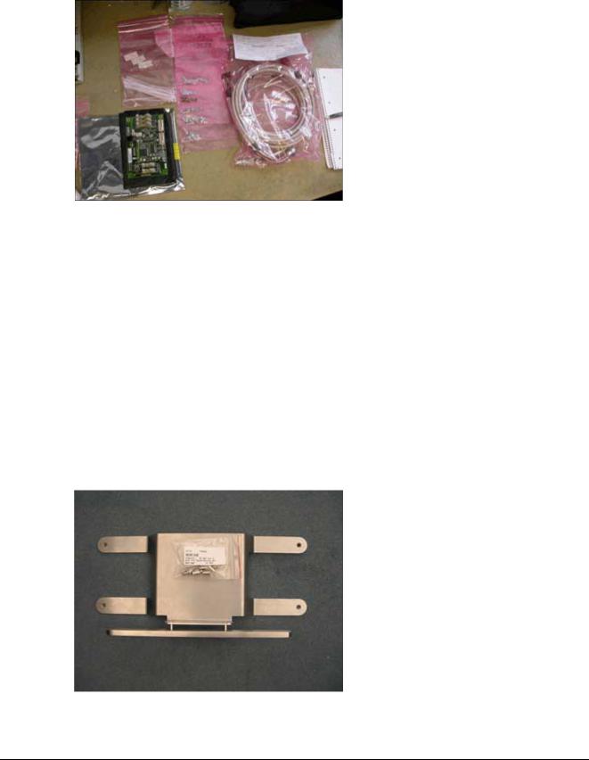
RUI Adapter Kit
Fig. 3: RUI Adapter Kit
The delivery volume for the RUI adapter kit includes:
•Circuit board D32 Interface, Mat. No. 10096538
•RUI cable set
-D32.X1 - X30 cable (round ODU connector)
-D32.X2 - D30.X12 cable
-D32.X4 - D1.X3 cable
-D32.X6 - X31.1 and X31.2 cable
-D32.X8 - X40 cable
-Protective conductor D32.PE - D32. mounting plate
•Small parts (insulating tubes, nuts, washers, contact disks, cable ties...)
RUI mount
Fig. 4: RUI mount
Siemens AG |
SPR2-330.814.03.02.02 |
Page 9 of 48 |
ARCADIS Avantic |
Medical Solutions |
06.07 |
CS PS SP |
|

10 |
Assembling the RUI adapter kit |
•RUI mount adapter kit
•Small parts (4 Allen screws, 4 spring nuts)
ARCADIS Avantic |
SPR2-330.814.03.02.02 |
Page 10 of 48 |
Siemens AG |
|
06.07 |
CS PS SP |
Medical Solutions |
Assembling the RUI adapter kit |
11 |
Preparatory work steps
Completely shut down lifting column
•Switch on the system and wait for it to boot up.
•Move the lifting column down to its lowest position.
•Leave the system on.
Short functional test of the existing control panel
•Briefly test the functionality of the existing control panel by selecting a different mode of operation and moving the collimator positions.
Opening the rear cover panel of the basic unit
•Switch the system off and wait until it turns off automatically.
•Disconnect the power plug from the power supply.
•Unplug the X10 monitor plug from the basic unit.
•Open the rear cover panel of the basic unit and lift.
•Unscrew the protective conductor from the cover panel.
•Set the cover panel a bit off to the side from the basic unit for better access.
Siemens AG |
SPR2-330.814.03.02.02 |
Page 11 of 48 |
ARCADIS Avantic |
Medical Solutions |
06.07 |
CS PS SP |
|

12 |
Assembling the RUI adapter kit |
Installing the D32 Circuit Board
Fig. 5: D32 Fitting panel
Pos. 1 D32 fitting panel; pivotable
Pos. 2 Threaded bolts with suspended insulating sleeves
Pos. 3 Adjustment screw in normal position
Pos. 4 Threaded bolts for cable clips
Pos. 5 Adjustment screw in service position
Pos. 6 Threaded bolts for protective conductor connection
Fig. 6: D32 Connector
Pos. 1 Threaded bolts with protective conductor
Pos. 2 Threaded bolts with protective conductor
•Remove the four insulators from the accessories kit.
•Attach the insulators onto the threaded bolts of the existing fitting panel.
•Place the new D32 circuit board onto the threaded bolts.
Position D32: connector D32.X5 top, connector D32.X2 bottom.
•In addition to the protective conductor D32.PE - D32 included, place the fitting panel onto the right bottom threaded bolt.
•Mount the D32 circuit board onto the four threaded bolts using the washers, contact disks and screw nuts provided.
ARCADIS Avantic |
SPR2-330.814.03.02.02 |
Page 12 of 48 |
Siemens AG |
|
06.07 |
CS PS SP |
Medical Solutions |

Assembling the RUI adapter kit |
13 |
•Place the other end of the protective conductor on the contact plate next to the fitting panel of the D32 circuit board and tighten onto the bottom threaded bolts (M4 screw nut, washer, contact disk). Make sure the protective conductor has good contact.
D32 Check S1
•Check the position of the D32.S1 DIP switch. Position S1.1: ON
Position S1.2 to S1.8: OFF
•Position of the DIP switch: See illustration
Fig. 7: D32 S1
Pos. 1 Position of D32.S1
Siemens AG |
SPR2-330.814.03.02.02 |
Page 13 of 48 |
ARCADIS Avantic |
Medical Solutions |
06.07 |
CS PS SP |
|
14 |
Assembling the RUI adapter kit |
Cabling
Changes to the existing cabling in the basic unit
Cable, connected to D1. X3
Fig. 8: D1.X3
Pos. 1 D1/D30 plug-in rack
Pos. 2 D1.X3 connector
Fig. 9: Cable clips for plug-in rack
Pos. 1 D1.X3 cable clips
Pos. 2 D30.X12 cable clips
ARCADIS Avantic |
SPR2-330.814.03.02.02 |
Page 14 of 48 |
Siemens AG |
|
06.07 |
CS PS SP |
Medical Solutions |

Assembling the RUI adapter kit |
15 |
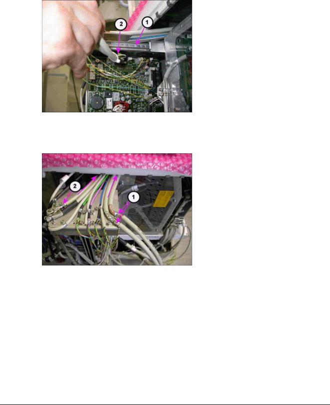
Fig. 10: D32.X5 cable
•Loosen the plug-in rack of the D1/D30 circuit board and place it horizontally into the service position (pull out).
•Loosen the X3 connector from the D1 circuit board.
NOTE |
|
|
2 cables are attached to the D1.X3 connector. |
||
|
|
|
|
|
|
•Loosen both cable clips for contacting the shielding of both cables on the top side of the plug-in rack.
•Remove any existing cable ties.
•Pull out the cables between the top side of the generator housing and the cover of the basic unit on the unit's right side.
•Continue to lay the cables along the existing cabling to the D32 circuit board.
•Slide the D1.X3 connector onto the D32.X5 circuit board.
NOTE |
|
|
The D1.X3 connector is labeled with D1.X3 / D32.X5 |
||
|
|
|
|
|
|
•Attach cable shielding to the grounding bracket to the right next to the D32 circuit board using the A5 clip (thicker cables), the A4 clip (for thinner cables), a washer, and the M4 screw nut. Make sure that the shielding makes good ground contact.
•Attach the cable shielding to the grounding bracket to the right next to the D32 circuit board using the A5 clip (thicker cables), the A4 clip (for thinner cables), a washer, and the M4 screw nut. Make sure that the shielding makes good ground contact.
Siemens AG |
SPR2-330.814.03.02.02 |
Page 15 of 48 |
ARCADIS Avantic |
Medical Solutions |
06.07 |
CS PS SP |
|
Loading...