


 Loading...
SINUMERIK
SINUMERIK 802D sl
Milling
Programming and Operating Manual
Valid for |
|
Control system |
Software version |
SINUMERIK 802D sl T/M |
1.4 SP7 |
11/2012
___________________
Preface
Description |
1 |
|
|
|
|
Software interface |
2 |
|
Turning On, Reference |
|
|
3 |
||
Point Approach |
||
|
|
|
Set up |
4 |
|
|
|
|
Manually Controlled Mode |
5 |
|
|
|
|
Automatic mode |
6 |
|
|
|
|
Part Programming |
7 |
|
|
|
|
System |
8 |
|
|
|
|
Programming |
9 |
|
|
|
|
Cycles |
10 |
|
|
|
|
Network operation |
11 |
|
|
|
|
Data backup |
12 |
|
|
|
|
PLC diagnostics |
13 |
|
|
|
|
Appendix |
A |
|
|
|
6FC5398-0CP10-7BA0

Legal information
Warning notice system
This manual contains notices you have to observe in order to ensure your personal safety, as well as to prevent damage to property. The notices referring to your personal safety are highlighted in the manual by a safety alert symbol, notices referring only to property damage have no safety alert symbol. These notices shown below are graded according to the degree of danger.
 DANGER
indicates that death or severe personal injury will result if proper precautions are not taken.
 WARNING
indicates that death or severe personal injury may result if proper precautions are not taken.
 CAUTION
indicates that minor personal injury can result if proper precautions are not taken.
NOTICE
indicates that property damage can result if proper precautions are not taken.
If more than one degree of danger is present, the warning notice representing the highest degree of danger will be used. A notice warning of injury to persons with a safety alert symbol may also include a warning relating to property damage.
Qualified Personnel
The product/system described in this documentation may be operated only by personnel qualified for the specific task in accordance with the relevant documentation, in particular its warning notices and safety instructions. Qualified personnel are those who, based on their training and experience, are capable of identifying risks and avoiding potential hazards when working with these products/systems.
Proper use of Siemens products
Note the following:
 WARNING
Siemens products may only be used for the applications described in the catalog and in the relevant technical documentation. If products and components from other manufacturers are used, these must be recommended or approved by Siemens. Proper transport, storage, installation, assembly, commissioning, operation and maintenance are required to ensure that the products operate safely and without any problems. The permissible ambient conditions must be complied with. The information in the relevant documentation must be observed.
Trademarks
All names identified by ® are registered trademarks of Siemens AG. The remaining trademarks in this publication may be trademarks whose use by third parties for their own purposes could violate the rights of the owner.
Disclaimer of Liability
We have reviewed the contents of this publication to ensure consistency with the hardware and software described. Since variance cannot be precluded entirely, we cannot guarantee full consistency. However, the information in this publication is reviewed regularly and any necessary corrections are included in subsequent editions.
Siemens AG |
Order number: 6FC5398-0CP10-7BA0 |
Copyright © Siemens AG 2000 - 2012. |
Industry Sector |
08/2013 Technical data subject to change |
All rights reserved |
Postfach 48 48 |
|
|
90026 NÜRNBERG |
|
|
GERMANY |
|
|
Preface
SINUMERIK documentation
The SINUMERIK documentation is organized in the following categories:
●General documentation
●User documentation
●Manufacturer/service documentation
Additional information
You can find information on the following topics at www.siemens.com/motioncontrol/docu:
●Ordering documentation/overview of documentation
●Additional links to download documents
●Using documentation online (find and search in manuals/information)
Please send any questions about the technical documentation (e.g. suggestions for improvement, corrections) to the following address:
docu.motioncontrol@siemens.com
My Documentation Manager (MDM)
Under the following link you will find information to individually compile OEM-specific machine documentation based on the Siemens content:
www.siemens.com/mdm
Training
For information about the range of training courses, refer under:
●www.siemens.com/sitrain
SITRAIN - Siemens training for products, systems and solutions in automation technology
●www.siemens.com/sinutrain
SinuTrain - training software for SINUMERIK
FAQs
You can find Frequently Asked Questions in the Service&Support pages under Product Support. http://support.automation.siemens.com
Milling |
|
Programming and Operating Manual, 11/2012, 6FC5398-0CP10-7BA0 |
3 |

Preface
SINUMERIK
You can find information on SINUMERIK under the following link: www.siemens.com/sinumerik
Target group
This publication is intended for programmers, planning engineers, machine operators and system operators.
Benefits
With the Programming and Operating Manual, the target group can develop, write, test and debug programs and software user interfaces.
In addition, it enables the target group to operate the hardware and software of a machine.
Standard scope
This documentation only describes the functionality of the standard version. Extensions or changes made by the machine tool manufacturer are documented by the machine tool manufacturer.
Other functions not described in this documentation might be executable in the control. This does not, however, represent an obligation to supply such functions with a new control or when servicing.
For the sake of simplicity, this documentation does not contain all detailed information about all types of the product and cannot cover every conceivable case of installation, operation, or maintenance.
Technical Support
You will find telephone numbers for other countries for technical support in the Internet under http://www.siemens.com/automation/service&support
EC Declaration of Conformity
The EC Declaration of Conformity for the EMC Directive can be found on the Internet at: http://support.automation.siemens.com
Here, enter the number 15257461 as the search term or contact your local Siemens office.
|
Milling |
4 |
Programming and Operating Manual, 11/2012, 6FC5398-0CP10-7BA0 |
Contents
|
Preface |
...................................................................................................................................................... |
3 |
1 |
Description............................................................................................................................................... |
11 |
|
|
1.1 ....................................................................................................... |
Control and display elements |
11 |
|
1.2 ............................................................................................................. |
Error and status displays |
12 |
|
1.3 ............................................................. |
Key definition of the full CNC keyboard (vertical format) |
13 |
|
1.4 ................................................................................. |
Key definition of the machine control panel |
15 |
|
1.5 ..................................................................................................................... |
Coordinate systems |
16 |
2 |
Software ....................................................................................................................................interface |
21 |
|
|
2.1 ............................................................................................................................... |
Screen layout |
21 |
|
2.2 ........................................................................................................................ |
Standard softkeys |
25 |
|
2.3 ........................................................................................................................... |
Operating areas |
26 |
|
2.4 ........................................................................................................................... |
The help system |
27 |
3 |
Turning ...................................................................................................On, Reference Point Approach |
29 |
|
|
3.1 ............................................................................. |
Turning on and approaching reference points |
29 |
4 |
Set up...................................................................................................................................................... |
|
31 |
|
4.1 ...................................................................................................... |
Entering tools and tool offsets |
31 |
|
4.1.1 ............................................................................................................................ |
Create new tool |
36 |
|
4.1.2 ....................................................................................... |
Determining the tool offsets (manually) |
37 |
|
4.1.3 .............................................................................. |
Determining tool offsets using a probe (auto) |
41 |
|
4.1.4 .............................................................................................................................. |
Probe settings |
44 |
|
4.2 ............................................................................................................................ |
Tool monitoring |
46 |
|
4.3 .................................................................................................. |
Entering/modifying a work offset |
48 |
|
4.3.1 ......................................................................................................... |
Determining the work offset |
49 |
|
4.4 .................................................................................................................... |
Program setting data |
51 |
|
4.5 ................................................................................................................ |
Arithmetic parameter R |
55 |
5 |
Manually .......................................................................................................................Controlled Mode |
57 |
|
|
5.1 ........................................................................................................... |
Manually Controlled Mode |
57 |
|
5.2 ......................................................................................... |
JOG mode - "Position" operating area |
58 |
|
5.2.1 ................................................................................................................. |
Assigning handwheels |
62 |
|
5.3 ................................................................. |
MDA mode (manual input) "Position" operating area |
63 |
|
5.3.1 ....................................................................................................................................... |
Teach In |
67 |
|
5.3.2 .................................................................................................................................. |
Face milling |
70 |
6 |
Automatic .......................................................................................................................................mode |
73 |
|
|
6.1 ...................................................................................................................... |
AUTOMATIC mode |
73 |
Milling |
|
|
|
Programming and Operating Manual, 11/2012, 6FC5398-0CP10-7BA0 |
5 |
||

Contents
|
6.2 |
Selection and start of a part program .......................................................................................... |
78 |
|
6.3 |
Block search ................................................................................................................................ |
80 |
|
6.4 |
Simultaneous recording .............................................................................................................. |
82 |
|
6.5 |
Stop / cancel a part program ....................................................................................................... |
85 |
|
6.6 |
Reapproach after cancellation .................................................................................................... |
85 |
|
6.7 |
Repositioning after interruption ................................................................................................... |
86 |
|
6.8 |
Execute from external ................................................................................................................. |
86 |
7 |
Part Programming.................................................................................................................................... |
91 |
|
|
7.1 |
Part programming overview ........................................................................................................ |
91 |
|
7.2 |
Enter new program ...................................................................................................................... |
95 |
|
7.3 |
Editing part program or text files ................................................................................................. |
96 |
|
7.4 |
Simulation .................................................................................................................................... |
99 |
|
7.5 |
Calculate contour elements ....................................................................................................... |
103 |
|
7.6 |
Free contour programming ........................................................................................................ |
111 |
|
7.6.1 |
Program a contour .................................................................................................................... |
114 |
|
7.6.2 |
Define a start point .................................................................................................................... |
116 |
|
7.6.3 |
Softkeys and parameters .......................................................................................................... |
118 |
|
7.6.4 |
Parameterize contour element .................................................................................................. |
123 |
|
7.6.5 |
Graphic representation of the contour ...................................................................................... |
126 |
|
7.6.6 |
Specify contour elements in polar coordinates, close the contour ........................................... |
127 |
|
7.6.7 |
Parameter description of straight line/circle contour elements ................................................. |
130 |
|
7.6.8 |
Programming example for milling ............................................................................................. |
132 |
8 |
System |
................................................................................................................................................... |
139 |
|
8.1 |
"System" operating area ........................................................................................................... |
139 |
|
8.2 |
SYSTEM - "Start - up" softkeys ................................................................................................... |
144 |
|
8.3 .......................................................................................... |
SYSTEM - "Machine data" softkeys |
145 |
|
8.4 ..................................................................................................... |
SYSTEM - "Service display" |
152 |
|
8.4.1 ..................................................................................................... |
SYSTEM - "Service display" |
152 |
|
8.4.2 ................................................................................................................................... |
Action log |
153 |
|
8.4.3 ................................................................................................................................ |
Servo trace |
154 |
|
8.4.4 ................................................................................................................... |
Version/HMI details |
158 |
|
8.4.5 ............................................................................................................................. |
Service MSG |
161 |
|
8.4.6 .................................................................................................................................. |
Date, time |
168 |
|
8.5 ........................................................................................................ |
SYSTEM - "PLC" softkeys |
169 |
|
8.6 ........................................................................................... |
SYSTEM - "Start - up files" softkeys |
176 |
|
8.7 ........................................................................... |
SYSTEM - "Commissioning wizard" softkeys |
181 |
|
8.8 ............................................................................................................................. |
Alarm display |
183 |
9 |
Programming......................................................................................................................................... |
185 |
|
|
9.1 ............................................................................ |
Fundamental Principles of NC Programming |
185 |
|
9.1.1 ......................................................................................................................... |
Program names |
185 |
|
|
|
Milling |
6 |
|
Programming and Operating Manual, 11/2012, 6FC5398 - 0CP10 -7BA0 |
|

Contents
9.1.2 |
Program structure...................................................................................................................... |
185 |
9.1.3 |
Word structure and address....................................................................................................... |
186 |
9.1.4 |
Block format............................................................................................................................... |
187 |
9.1.5 |
Fonts.......................................................................................................................................... |
189 |
9.1.6 |
List of instructions...................................................................................................................... |
190 |
9.1.7 |
Interactively call the window from the part program (MMC)...................................................... |
206 |
9.2 |
Positional data ........................................................................................................................... |
208 |
9.2.1 |
Programming dimensions.......................................................................................................... |
208 |
9.2.2 |
Plane selection: G17 to G19...................................................................................................... |
209 |
9.2.3 |
Absolute/incremental dimensioning: G90, G91, AC, IC............................................................. |
210 |
9.2.4 |
Dimensions in metric units and inches: G71, G70, G710, G700............................................... |
212 |
9.2.5 |
Polar coordinates, pole definition: G110, G111, G112.............................................................. |
213 |
9.2.6 |
Programmable work offset: TRANS, ATRANS.......................................................................... |
215 |
9.2.7 |
Programmable rotation: ROT, AROT......................................................................................... |
216 |
9.2.8 |
Programmable scaling factor: SCALE, ASCALE....................................................................... |
218 |
9.2.9 |
Programmable mirroring: MIRROR, AMIRROR ........................................................................ |
219 |
9.2.10 |
Workpiece clamping - settable work offset: G54 to G59, G500, G53, G153............................. |
221 |
9.2.11 |
Programmable working area limitation: G25, G26, WALIMON, WALIMOF .............................. |
222 |
9.3 |
Axis movements......................................................................................................................... |
225 |
9.3.1 |
Linear interpolation with rapid traverse: G0............................................................................... |
225 |
9.3.2 |
Linear interpolation with feedrate: G1........................................................................................ |
226 |
9.3.3 |
Circular interpolation: G2, G3 .................................................................................................... |
228 |
9.3.4 |
Circular interpolation via intermediate point: CIP....................................................................... |
233 |
9.3.5 |
Circle with tangential transition: CT........................................................................................... |
234 |
9.3.6 |
Helix interpolation: G2/G3, TURN.............................................................................................. |
235 |
9.3.7 |
Thread cutting with constant lead: G33..................................................................................... |
236 |
9.3.8 |
Tapping with compensating chuck: G63.................................................................................... |
237 |
9.3.9 |
Thread interpolation: G331, G332............................................................................................. |
238 |
9.3.10 |
Fixed point approach: G75......................................................................................................... |
240 |
9.3.11 |
Reference point approach: G74................................................................................................. |
241 |
9.3.12 |
Measuring with touch-trigger probe: MEAS, MEAW.................................................................. |
242 |
9.3.13 |
Tangential control: TANG, TANGON, TANGOF, TLIFT, TANGDEL......................................... |
243 |
9.3.14 |
Feedrate F.................................................................................................................................. |
246 |
9.3.15 |
Feedrate override for circles: CFTCP, CFC............................................................................... |
247 |
9.3.16 |
Exact stop / continuous-path control mode: G9, G60, G64....................................................... |
248 |
9.3.17 |
Acceleration pattern: BRISK, SOFT........................................................................................... |
251 |
9.3.18 |
Percentage acceleration override: ACC .................................................................................... |
252 |
9.3.19 |
Traversing with feedforward control: FFWON, FFWOF............................................................. |
253 |
9.3.20 Enhanced surface quality through compressor: COMPCAD..................................................... |
253 |
|
9.3.21 |
Fourth axis ................................................................................................................................. |
255 |
9.3.22 |
Dwell time: G4............................................................................................................................ |
256 |
9.3.23 |
Travel to fixed stop..................................................................................................................... |
257 |
9.3.24 |
Feed reduction with corner deceleration (FENDNORM, G62, G621)........................................ |
260 |
9.3.25 |
Coupled axes............................................................................................................................. |
262 |
9.3.25.1 |
Coupled motion (TRAILON, TRAILOF) ..................................................................................... |
262 |
9.3.25.2 |
Coupled axis motion (TRAILON, TRAILOF): Further Information............................................. |
264 |
9.3.25.3 |
Master/slave group (MASLDEF, MASLDEL, MASLON, MASLOF, MASLOFS) ....................... |
266 |
9.3.25.4 |
Master/slave group (MASLDEF, MASLDEL, MASLON, MASLOF, MASLOFS): Further |
|
|
Information................................................................................................................................. |
268 |
9.4 |
Spindle movements ................................................................................................................... |
269 |
Milling |
|
|
Programming and Operating Manual, 11/2012, 6FC5398-0CP10-7BA0 |
7 |
|

Contents
|
9.4.1 |
Spindle speed S, directions of rotation ..................................................................................... |
269 |
|
9.4.2 |
Spindle speed limitation: G25, G26 .......................................................................................... |
270 |
|
9.4.3 |
Spindle positioning: SPOS ........................................................................................................ |
271 |
|
9.4.4 |
Gear stages ............................................................................................................................... |
272 |
|
9.5 |
Contour programming support .................................................................................................. |
272 |
|
9.5.1 |
Rounding, chamfer .................................................................................................................... |
272 |
|
9.5.2 |
Contour definition programming ................................................................................................ |
276 |
|
9.6 |
Tool and tool offset .................................................................................................................... |
278 |
|
9.6.1 |
General Information .................................................................................................................. |
278 |
|
9.6.2 |
Tool T ........................................................................................................................................ |
279 |
|
9.6.3 |
Tool compensation number D ................................................................................................... |
280 |
|
9.6.4 |
Selecting the tool radius compensation: G41, G42 .................................................................. |
283 |
|
9.6.5 |
Corner behavior: G450, G451 ................................................................................................... |
285 |
|
9.6.6 |
Tool radius compensation OFF: G40 ........................................................................................ |
287 |
|
9.6.7 |
Special cases of the tool radius compensation ......................................................................... |
288 |
|
9.6.8 |
Example of tool radius compensation ....................................................................................... |
289 |
|
9.7 |
Miscellaneous function M .......................................................................................................... |
291 |
|
9.8 |
H function .................................................................................................................................. |
292 |
|
9.9 |
Arithmetic parameters, LUD and PLC variables ....................................................................... |
293 |
|
9.9.1 |
Arithmetic parameter R ............................................................................................................. |
293 |
|
9.9.2 |
Local User Data (LUD) .............................................................................................................. |
295 |
|
9.9.3 |
Reading and writing PLC variables ........................................................................................... |
297 |
|
9.10 |
Program jumps .......................................................................................................................... |
298 |
|
9.10.1 |
Jump destination for program jumps ......................................................................................... |
298 |
|
9.10.2 |
Unconditional program jumps ................................................................................................... |
298 |
|
9.10.3 |
Conditional program jumps ....................................................................................................... |
299 |
|
9.10.4 |
Program example for jumps ...................................................................................................... |
301 |
|
9.11 |
Subroutine technique ................................................................................................................ |
303 |
|
9.11.1 |
General information ................................................................................................................... |
303 |
|
9.11.2 |
Calling machining cycles ........................................................................................................... |
306 |
|
9.11.3 |
Modal subroutine call ................................................................................................................ |
306 |
|
9.11.4 |
Execute external subroutine (EXTCALL) .................................................................................. |
307 |
|
9.12 |
Timers and workpiece counters ................................................................................................ |
310 |
|
9.12.1 |
Runtime timer ............................................................................................................................ |
310 |
|
9.12.2 |
Workpiece counter .................................................................................................................... |
311 |
|
9.13 |
Language commands for tool monitoring .................................................................................. |
313 |
|
9.13.1 |
Tool monitoring overview .......................................................................................................... |
313 |
|
9.13.2 |
Tool life monitoring .................................................................................................................... |
315 |
|
9.13.3 |
Workpiece count monitoring ...................................................................................................... |
317 |
|
9.14 |
Smooth approach and retraction ............................................................................................... |
322 |
|
9.15 |
Milling of the peripheral surface - TRACYL ............................................................................... |
328 |
10 |
Cycles |
.................................................................................................................................................... |
335 |
|
10.1 |
Overview of cycles .................................................................................................................... |
335 |
|
10.2 |
Programming cycles .................................................................................................................. |
337 |
|
10.3 .......................................................................... |
Graphical cycle support in the program editor |
339 |
|
|
|
Milling |
8 |
|
Programming and Operating Manual, 11/2012, 6FC5398 - 0CP10 -7BA0 |
|

Contents
10.4 |
Drilling cycles............................................................................................................................. |
341 |
10.4.1 |
General information ................................................................................................................... |
341 |
10.4.2 |
Requirements............................................................................................................................. |
342 |
10.4.3 |
Drilling, centering - CYCLE81.................................................................................................... |
344 |
10.4.4 |
Drilling, counterboring - CYCLE82:............................................................................................ |
347 |
10.4.5 |
Deep-hole drilling - CYCLE83.................................................................................................... |
350 |
10.4.6 |
Rigid tapping - CYCLE84........................................................................................................... |
354 |
10.4.7 |
Tapping with compensating chuck - CYCLE840 ....................................................................... |
358 |
10.4.8 |
Reaming 1 (Drilling 1) – CYCLE85............................................................................................ |
365 |
10.4.9 |
Boring (Drilling 2) – CYCLE86 ................................................................................................... |
368 |
10.4.10 |
Boring with stop 1 (boring 3) – CYCLE87.................................................................................. |
371 |
10.4.11 |
Drilling with stop 2 (Drilling 4) - CYCLE88................................................................................. |
374 |
10.4.12 |
Reaming 2 (Drilling 5) – CYCLE89............................................................................................ |
376 |
10.5 |
Drilling pattern cycles................................................................................................................. |
378 |
10.5.1 |
Requirements............................................................................................................................. |
378 |
10.5.2 |
Row of holes - HOLES1............................................................................................................. |
379 |
10.5.3 |
Circle of holes - HOLES2........................................................................................................... |
383 |
10.6 |
Milling cycles.............................................................................................................................. |
386 |
10.6.1 |
Requirements............................................................................................................................. |
386 |
10.6.2 |
Face milling - CYCLE71............................................................................................................. |
387 |
10.6.3 |
Contour milling - CYCLE72........................................................................................................ |
393 |
10.6.4 |
Rectangular spigot milling - CYCLE76 ...................................................................................... |
403 |
10.6.5 |
Circular spigot milling - CYCLE77 ............................................................................................. |
409 |
10.6.6 |
Long holes located on a circle - LONGHOLE............................................................................ |
414 |
10.6.7 |
Slots on a circle - SLOT1........................................................................................................... |
419 |
10.6.8 |
Circumferential slot - SLOT2...................................................................................................... |
426 |
10.6.9 |
Milling a rectangular pocket - POCKET3................................................................................... |
432 |
10.6.10 |
Milling a circular pocket - POCKET4 ......................................................................................... |
441 |
10.6.11 |
Thread milling - CYCLE90......................................................................................................... |
446 |
10.7 |
Error messages and error handling........................................................................................... |
452 |
10.7.1 |
General Information................................................................................................................... |
452 |
10.7.2 |
Error handling in the cycles........................................................................................................ |
452 |
10.7.3 |
Overview of cycle alarms........................................................................................................... |
453 |
10.7.4 |
Messages in the cycles.............................................................................................................. |
455 |
11 Network operation.................................................................................................................................. |
457 |
|
11.1 |
Interfaces and functions of the RCS802 tool............................................................................. |
458 |
11.2 |
Working on the basis of a network connection.......................................................................... |
459 |
11.3 |
User management ..................................................................................................................... |
460 |
11.4 |
User log in - RCS log in ............................................................................................................. |
461 |
11.5 |
Setting the connections on the RCS802 tool............................................................................. |
462 |
11.6 |
Establishing an RS232 connection to the control...................................................................... |
463 |
11.7 |
Establishing a peer-to-peer Ethernet connection to the control................................................. |
464 |
11.8Establish the Ethernet network connection to the control (only with SINUMERIK 802D sl
|
pro)............................................................................................................................................. |
466 |
11.9 |
Additional network functions...................................................................................................... |
468 |
11.9.1 |
Sharing directories..................................................................................................................... |
468 |
Milling |
|
|
Programming and Operating Manual, 11/2012, 6FC5398-0CP10-7BA0 |
9 |
|

Contents
|
11.9.2 |
Connecting / disconnecting network drives ............................................................................... |
469 |
12 |
Data backup .......................................................................................................................................... |
473 |
|
|
12.1 |
Data transfer via RS232 interface ............................................................................................. |
473 |
|
12.2 |
Creating / reading in / reading out a start - up archive ................................................................ |
475 |
|
12.3 |
Reading in / reading out PLC projects ...................................................................................... |
477 |
|
12.4 |
Copying and pasting files .......................................................................................................... |
478 |
13 |
PLC diagnostics..................................................................................................................................... |
479 |
|
|
13.1 |
PLC diagnosis represented as a ladder diagram ...................................................................... |
479 |
|
13.2 |
Screen layout ............................................................................................................................ |
480 |
|
13.3 |
Operating options ...................................................................................................................... |
481 |
A |
Appendix |
................................................................................................................................................ |
495 |
|
A.1 |
Miscellaneous ........................................................................................................................... |
495 |
|
A.1.1 ....................................................................................................................... |
Pocket calculator |
495 |
|
A.1.2 ............................................................................................................ |
Editing asian characters |
496 |
|
A.1.2.1 .................................................................................................................... |
Simplified Chinese |
497 |
|
A.1.2.2 ................................................................................... |
Traditional Chinese (as used in Taiwan) |
500 |
|
A.1.2.3 ............................................................................................................. |
Importing the dictionary |
503 |
|
A.1.2.4 ....................................................................................................................................... |
Korean |
504 |
|
A.2 ....................................................................................................... |
Overview of documentation |
506 |
|
Index...................................................................................................................................................... |
|
507 |
|
Milling |
10 |
Programming and Operating Manual, 11/2012, 6FC5398-0CP10-7BA0 |
Description |
1 |
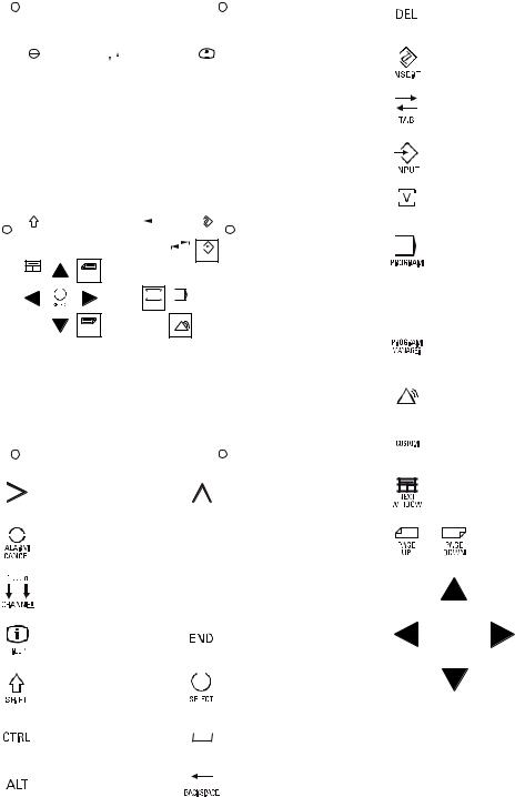
1.1Control and display elements
Operator control elements
The defined functions are called up via the horizontal and vertical softkeys. For a description, please refer to this manual:
9HUWLFDO VRIWNH\V
+RUL]RQWDO VRIWNH\V
Figure 1-1 CNC operator panel
Milling |
|
Programming and Operating Manual, 11/2012, 6FC5398-0CP10-7BA0 |
11 |

Description
1.2 Error and status displays
1.2Error and status displays
LED displays on the CNC operator panel (PCU)
The following LEDs are installed on the CNC operator panel.
(55 5'< 1& &)
The individual LEDs and their functions are described in the table below.
Table 1- 1 Status and error displays
LED |
Significance |
ERR (red) |
Serious error, remedy through power OFF/ON |
RDY (green) |
Ready for operation |
NC (yellow) |
Signoflife monitoring |
CF (yellow) |
Reading from/writing to CF card |
References
You can find information on error description in the SINUMERIK 802D sl Diagnostics Manual
|
Milling |
12 |
Programming and Operating Manual, 11/2012, 6FC5398-0CP10-7BA0 |
|
|
|
|
|
|
|
|
|
|
|
|
|
|
|
|
|
|
|
|
|
|
|
|
|
|
|
Description |
|
|
|
|
|
|
|
|
|
|
|
|
|
|
|
|
1.3 Key definition of the full CNC keyboard (vertical format) |
|||||||||||
1.3 |
|
|
|
|
Key definition of the full CNC keyboard (vertical format) |
||||||||||||||||||||||
|
|
|
|
|
|
|
|
|
|
|
|
|
|
|
|
|
|
|
|
|
|
|
|
|
&OHDU NH\ |
||
|
|
|
|
|
|
|
|
|
|
|
|
|
|
|
|
|
|
|
|
|
|
|
|
|
|||
|
|
|
|
|
|
|
|
|
|
|
|
|
|
|
|
|
|
|
|
|
|
|
|
|
|
|
|
|
|
|
|
|
|
|
|
|
|
|
|
|
|
|
|
|
|
|
|
|
|
|
|
|
|
|
|
|
|
|
|
|
|
|
|
Q |
|
|
|
|
|
|
|
|
|
|
|
|
|
|
|
|
|
|
|
|
|
$/$50 |
|
|
|
|
|
|
|
|
|
|
|
|
|
|
|
|
|
|
|
|
|
|
|
||
|
|
|
|
|
|
|
|
|
|
|
|
|
|
+(/3 |
|
|
|
|
|
|
|
|
|
|
|
|
|
|
|
&$1&(/ |
|
|
&+$11(/ |
|
|
|
|
|
|
|
|
|
|
|
|
|
|
|
|
,QVHUW NH\ |
|||||
|
|
|
|
|
|
|
|
|
|
|
|
|
|
|
|
|
|
|
|
|
|
|
|
|
|
|
|
|
|
2 |
1 |
(* |
? |
|
|
|
|
|
|
|
|
|
|
|
|
|
|
|
|
|
|
|
|
||
|
|
3 |
|
|
|
|
|
|
|
|
|
|
|
|
|
|
|
|
|||||||||
|
|
|
|
|
|
|
|
|
|
|
|
|
|
|
|
|
|
|
|
|
|
|
|
|
|||
|
|
8 |
; |
9 < |
:= |
4 |
& |
|
|
|
|
|
|
|
|
|
|
|
|
|
|
|
7DEXODWRU |
||||
|
|
|
|
|
|
|
|
|
|
|
|
|
|
|
|
|
|
|
|
|
|
|
|
|
|
|
|
|
|
|
|
|
|
|
|
|
|
|
|
|
|
|
|
|
|
|
|
|
|
|
|
|
|
|
|
|
|
|
, |
|
$ - |
. |
5 |
|
@ |
# |
|
|
|
|
|
|
|
|
|
|
|
|
|
|
|||
|
|
|
|
|
|
|
|
|
|
|
|
|
|
|
|
|
|
|
|
|
|
|
|
|
(17(5 ,QSXW NH\ |
||
|
|
0 |
6 |
7 |
|
/ |
|
|
|
|
! |
|
|
|
|
|
|
|
|
|
|
|
|
|
|||
|
|
|
|
|
|
|
|
|
|
|
|
|
|
|
|
||||||||||||
|
|
|
|
|
|
|
|
|
|
|
|
|
|
|
|
|
|
|
|
|
|
|
|
|
|
|
|
|
|
|
|
|
|
|
|
|
|
|
|
|
|
|
|
|
|
|
|
|
|
|
|
|
|
|
|
|
|
> |
|
|
|
_ |
|
|
" |
|
|
|
|
|
|
|
|
|
|
|
|
|
|
|
|
|
|
|
|
|
|
|
|
+ |
|
|
|
|
|
|
|
|
|
|
|
|
|
|
|
|
|
|
|
||
|
|
|
) |
|
' |
|
|
% |
|
|
|
|
|
|
|
|
|
|
|
|
|
|
|
326,7,21 RSHUDWLQJ DUHD NH\ 3RVLWLRQ |
|||
|
|
|
|
|
|
|
|
|
|
|
|
|
|
|
|
|
|
|
|
|
|
|
|
|
RSHUDWLQJ DUHD |
||
|
|
|
|
|
|
|
|
|
|
|
|
|
|
|
|
|
|
|
|
|
|
|
|
|
|||
|
|
|
|
|
|
|
|
|
|
|
|
|
|
|
|
|
326,7,21 |
|
|
|
|
|
|
|
|||
|
|
|
|
|
|
$/7 |
|
|
|
|
|
|
|
|
|
|
|
|
|
|
|
|
|
|
|
|
|
|
|
|
|
|
&75/ |
|
|
|
|
|
|
|
|
|
|
|
|
|
|
|
|
|
|
|
|
|
|
|
|
|
|
|
|
|
|
|
|
%$&.63$&( |
'(/ |
|
|
|
|
|
|
|
|
|
|
|
|
|
|
||
|
|
6+,)7 |
|
|
|
|
|
|
|
|
|
,16(57 |
|
|
|
|
|
|
|
|
|
|
|
|
|
||
|
|
|
|
|
|
|
|
|
|
|
|
|
|
|
|
|
|
|
|
|
|
|
|
|
352*5$0 RSHUDWLQJ DUHD NH\ |
||
|
|
|
|
|
|
|
|
|
|
|
|
|
|
|
|
|
|
|
|
|
|
|
|
|
|||
|
|
|
|
|
|
|
|
|
|
|
|
|
|
|
|
|
|
|
|
|
|
|
|
|
|||
|
|
|
|
|
|
|
|
|
|
|
|
7$% |
|
|
|
|
|
|
|
|
|
|
|
|
|
|
|
|
|
|
|
|
|
|
|
|
|
|
|
|
|
,1387 |
|
|
|
|
|
|
|
|
|
|
RSHUDWLQJ DUHD SURJUDP |
||
|
|
1(;7 |
|
3$*( |
|
|
|
|
|
|
|
|
|
|
|
|
|
|
|
|
|
|
|
|
|
||
|
|
|
|
|
|
|
|
|
|
|
|
|
|
|
|
|
|
|
|
|
|
|
|
||||
|
|
|
|
|
|
83 |
|
|
|
|
|
|
|
|
|
|
|
|
|
|
|
|
|
|
|
|
|
|
|
:,1'2: |
|
|
|
|
|
|
|
|
|
|
|
|
|
|
|
|
|
|
|
|
|
|
|
||
|
|
|
|
|
|
|
|
|
|
|
|
|
|
2))6(7 |
|
|
|
|
|
|
|
|
|
|
|
||
|
|
|
|
|
|
|
|
|
|
|
|
|
|
|
|
|
2))6(7 |
|
|
|
|
|
|
|
|||
|
|
|
|
|
|
|
|
|
|
0 |
|
|
|
|
|
|
|
|
|
|
|
|
|
|
|
|
|
|
|
|
|
|
|
|
|
|
|
|
|
|
|
3$5$0 |
|
|
|
|
|
|
|
|
|
|
2))6(7 3$5$0 RSHUDWLQJ DUHD NH\ |
||
|
|
|
|
|
|
|
|
|
|
326,7,21 |
352*5$0 |
|
|
|
|
3$5$0 |
|
|
|
|
|
|
|
||||
|
|
|
|
|
|
|
|
|
|
|
|
|
|
|
|
|
|
|
|
|
|
|
|
|
3DUDPHWHU RSHUDWLQJ DUHD |
||
|
|
|
|
|
|
|
|
|
|
|
|
6<67(0 |
|
|
|
|
|
|
|
|
|
|
|
|
|
|
|
|
|
|
|
|
|
|
|
|
|
|
3URJUDP |
|
|
|
|
|
|
|
|
|
|
|
|
|
|
|
|
|
|
|
|
|
|
|
|
|
|
|
|
|
|
&86720 |
|
|
|
|
|
|
|
|
|
|
|
|
|
|
|
(1' |
|
|
|
|
|
|
|
|
|
|
|
|
|
|
|
|
|
|
|
|
|
|
|
||
|
|
|
|
|
|
3$*( |
|
|
|
|
0DQDJHU |
|
|
|
|
|
|
|
|
|
|
|
|
|
|
|
|
|
|
|
|
|
|
'2:1 |
|
|
|
|
|
|
|
|
|
|
|
|
|
|
|
|
|
|
|
|
|
|
|
|
|
|
|
|
|
|
|
|
|
$/$50 |
|
|
|
|
|
|
|
|
|
|
|
|
|
|
|
|
|
|
|
|
|
|
|
|
|
|
|
|
|
|
|
|
|
|
|
|
|
|
|
|
352*5$0 0$1$*(5 RSHUDWLQJ DUHD NH\ |
||
|
|
|
|
|
|
|
|
|
|
|
|
|
|
|
|
|
|
|
|
|
|
|
|
|
3URJUDP 0DQDJHU RSHUDWLQJ DUHD |
||
|
|
|
|
|
|
|
|
|
|
|
|
|
|
|
|
|
|
|
|
|
|
|
|
|
|||
|
|
|
|
|
|
|
|
|
|
|
|
|
|
|
|
|
|
|
|
|
|
|
|
|
|
|
|
|
|
|
|
|
|
|
|
|
|
|
|
|
|
|
|
|
6<67(0 |
|
|
|
|
|
|
|
|||
|
|
|
|
|
|
|
|
|
|
|
|
|
|
|
|
|
|
|
|
|
|
|
|
|
6<67(0 $/$50 RSHUDWLQJ DUHD NH\ |
||
|
|
|
|
|
|
|
|
|
|
|
|
|
|
|
|
|
|
|
|
|
|
|
|
|
6\VWHP $ODUP RSHUDWLQJ DUHD |
||
|
|
|
|
|
|
|
|
|
|
|
|
|
|
|
|
|
$/$50 |
|
|
|
|
|
|
|
|
||
|
|
|
|
|
|
|
|
|
|
|
|
|
|
|
|
|
|
|
|
|
|
|
|
|
|
&86720 RSHUDWLQJ DUHD NH\ |
|
|
|
|
|
|
|
|
|
|
|
|
|
|
|
|
|
|
|
|
|
|
|
|
|
|
|
||
|
|
|
|
|
|
|
|
|
|
|
|
|
|
|
|
|
|
|
|
|
|
|
|
|
|
8VHU RSHUDWLQJ DUHD |
|
|
|
|
|
|
|
|
|
|
|
|
|
|
|
|
|
|
|
|
|
|
|
|
|
|
1RW DVVLJQHG |
||
|
|
|
|
|
|
|
|
|
|
|
|
|
|
|
|
|
|
|
|
|
|
|
|
|
|||
|
|
|
|
|
|
|
|
|
|
|
|
|
|
|
|
|
|
|
|
|
|
|
|
|
|||
|
|
|
|
|
(7& NH\ |
|
|
|
|
|
|
|
|
5HFDOO NH\ |
|
|
|
|
|
|
|
|
|
|
|
||
|
|
|
|
|
|
|
|
|
|
|
|
|
|
|
|
|
|
|
|
|
|
|
|
|
6FUROO NH\V |
||
|
|
|
|
|
|
|
|
|
|
|
|
|
|
|
|
|
|
|
|
|
|
|
|
|
|||
|
|
|
|
|
|
|
|
|
|
|
|
|
|
|
|
|
|
|
|
|
|
|
|
|
|||
|
|
|
|
|
|
|
|
|
|
|
|
|
|
|
|
|
|
|
|
|
|
|
|
|
|||
|
|
|
|
|
|
|
|
|
|
|
|
|
|
|
|
|
|
|
|
|
|
|
|
|
|||
|
|
|
|
|
$FNQRZOHGJH DODUP NH\ |
|
|
|
|
|
|
|
|
|
|
|
|
|
|
||||||||
|
|
|
|
|
1R IXQFWLRQ |
|
|
|
|
|
|
|
|
|
|
|
|
|
|
|
|
|
|
|
|||
|
|
|
|
|
|
|
|
|
|
|
|
|
|
|
|
|
|
|
|
|
|
|
|
||||
|
|
|
|
|
|
|
|
|
|
|
|
|
|
|
|
|
|
|
|
|
|
|
|
||||
|
|
|
|
|
|
|
|
|
|
|
|
|
|
|
|
|
|
|
|
|
|
|
|
||||
|
|
|
|
|
,QIR NH\ |
|
|
|
|
|
|
|
|
|
|
|
|
|
|
|
|
|
|
|
|
|
|
|
|
|
|
|
|
|
|
|
|
|
|
|
|
|
|
|
|
|
|
|
|
|
|
|
|
||
|
|
|
|
|
|
|
|
|
|
|
|
|
|
|
|
|
|
|
|
|
|
|
|
|
|
||
|
|
|
|
|
|
|
|
|
|
|
|
|
|
|
|
|
|
|
|
|
|
|
|
|
|
||
|
|
|
|
|
|
|
|
|
|
|
|
|
|
|
|
|
|
|
|
|
|
|
|
|
|
||
|
|
|
|
|
|
|
|
|
|
|
|
|
|
|
|
|
|
|
|
|
|
|
|
|
|
|
|
|
|
|
|
|
6KLIW NH\ |
|
|
|
|
|
|
|
|
|
6HOHFWLRQ NH\ WRJJOH NH\ |
|
|
|
|
|
|
|
|
&XUVRU NH\V |
|||
|
|
|
|
|
|
|
|
|
|
|
|
|
|
|
|
|
|
|
|
|
|
||||||
|
|
|
|
|
|
|
|
|
|
|
|
|
|
|
|
|
|
|
|
|
|
||||||
|
|
|
|
|
|
|
|
|
|
|
|
|
|
|
|
|
|
|
|
|
|
|
|
|
|
|
|
|
|
|
|
|
|
|
|
|
|
|
|
|
|
|
|
|
|
|
|
|
|
|
|
|
|
|
|
|
|
|
|
|
|
|
|
|
|
|
|
|
|
|
|
|
|
|
|
|
|
|
|
|
|
|
|
|
|
|
|
|
|
|
|
|
|
|
|
|
|
|
|
|
$ |
|
|
|
|
: |
|
|
|
|
|
|
|
|
|
|
&RQWURO NH\ |
|
|
|
|
|
|
|
6SDFH |
- |
|
|
|
= |
|
$OSKDQXPHULF NH\V |
|||||||
|
|
|
|
|
|
|
|
|
|
|
|
|
|
|
|
|
|
|
|
|
|
|
|
|
'RXEOH DVVLJQPHQW RQ WKH VKLIW OHYHO |
||
|
|
|
|
|
|
|
|
|
|
|
|
|
|
|
|
|
|
|
|
|
|
|
|
|
|
|
|
|
|
|
|
|
|
|
|
|
|
|
|
|
|
|
|
|
|
|
|
|
|
|
|
|
|
|
|
|
|
|
|
|
$/7 NH\ |
|
|
|
|
|
|
|
|
'HOHWH NH\ %DFNVSDFH |
|
|
|
|
|
|
1XPHULF NH\V |
||||||
|
|
|
|
|
|
|
|
|
|
|
|
|
|
|
|
|
|
|
|
|
|
|
|
|
'RXEOH DVVLJQPHQW RQ WKH VKLIW OHYHO |
||
|
|
|
|
|
|
|
|
|
|
|
|
|
|
|
|
|
|
|
|
|
|
|
|
|
|
|
|
Milling |
|
|
|
|
|
|
|
|
|
|
|
|
|
|
|
|
|
|
|
|
|
|
|
|
|
||
Programming and Operating Manual, 11/2012, 6FC5398-0CP10-7BA0 |
|
|
|
|
|
|
|
|
13 |
||||||||||||||||||

Description
1.3 Key definition of the full CNC keyboard (vertical format)
Hot keys
In the part program editor and in the input fields of the HMI, the following functions can be carried out with certain shortcut keys on the full CNC keyboard:
Shortcut key |
Function |
<CTRL> and <C> |
Copy selected text |
<CTRL> and <B> |
Select text |
<CTRL> and <X> |
Cut selected text |
<CTRL> and <V> |
Paste copied text |
<CTRL> and <P> |
Generates a screenshot of the actual screen and |
|
saves the image on CompactFlash Card |
|
(customer CF Card) under "screen802dsl.bmp " |
<CTRL> and <R> |
HMI restart |
<CTRL> and <S> |
Data backup in case of backlight failure |
|
The series start-up archive (Drive/NC/PLC/HMI) |
|
is exported with the most recent data onto the |
|
CompactFlash card with the name |
|
"802Dslibn.arc". |
<ALT> and <L> |
Toggling between only upper case letters and |
|
upper and lower case letters |
<ALT> and <H> or <HELP> key |
Call help system |
<ALT> and <S> |
Switch-in and switch-out the Editor for Asian |
|
characters |
|
Milling |
14 |
Programming and Operating Manual, 11/2012, 6FC5398-0CP10-7BA0 |

Description
1.4 Key definition of the machine control panel
1.4Key definition of the machine control panel


 =
= 
 <
<
; 


 ;
;
< 
 =
= 


5(6(7
&<&/( 67231& 6723
&<&/( 67$571& 67$57
(0(5*(1&< 6723
6SLQGOH 6SHHG 2YHUULGH 6SLQGOH RYHUULGH
8VHU GHILQHG NH\ ZLWK /('
8VHU GHILQHG NH\ ZLWKRXW /('
,1&5(0(17
,QFUHPHQW
-2*
5()(5(1&( 32,17 5HIHUHQFH SRLQW
$8720$7,&
6,1*/( %/2&. 6LQJOH EORFN
0$18$/ '$7$ 0DQXDO LQSXW
63,1'/( 67$57 &&: &RXQWHUFORFNZLVH
63,1'/( 6723
63,1'/( 67$57 &: &ORFNZLVH
5$3,' 75$9(56( 29(5/$< 5DSLG WUDYHUVH RYHUULGH
; ; ; D[LV
< < < D[LV
= = = D[LV
)HHGUDWH RYHUULGH )HHGUDWH RYHUULGH
Milling |
|
Programming and Operating Manual, 11/2012, 6FC5398-0CP10-7BA0 |
15 |
Description
1.5 Coordinate systems
Note
This documentation assumes an 802D standard machine control panel (MCP). Should you use a different MCP, the operation may be other than described herein.
1.5Coordinate systems
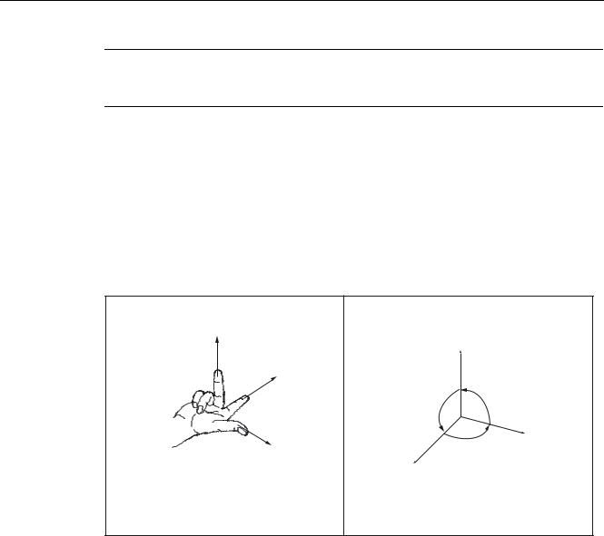
As a rule, a coordinate system is formed from three mutually perpendicular coordinate axes. The positive directions of the coordinate axes are defined using the so-called "3-finger rule" of the right hand. The coordinate system is related to the workpiece and programming takes place independently of whether the tool or the workpiece is being traversed. When programming, it is always assumed that the tool traverses relative to the coordinate system of the workpiece, which is intended to be stationary.
=
<
<
90° 90°
90° |
|
|
; |
;
=
Figure 1-2 Determination of the axis directions to one another; coordinate system for programming
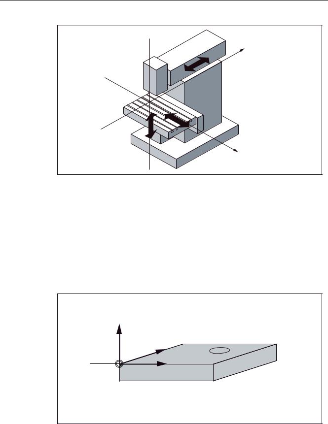
Machine coordinate system (MCS)
The orientation of the coordinate system relative to the machine depends on the respective machine type. It can be rotated in different positions.
The directions of the axes follow the "3-finger rule" of the right hand. Seen from in front of the machine, the middle finger of the right hand points in the opposite direction to the infeed of the main spindle.
|
Milling |
16 |
Programming and Operating Manual, 11/2012, 6FC5398-0CP10-7BA0 |
Description
1.5 Coordinate systems
=
<
;
Figure 1-3 Machine coordinates/axes using the example of a milling machine
The origin of this coordinate system is the machine zero.
This point is only a reference point which is defined by the machine manufacturer. It does not have to be approachable.
The traversing range of the machine axes can be in the negative range.
Workpiece coordinate system (WCS)
To describe the geometry of a workpiece in the workpiece program, a right-handed, rightangled coordinate system is also used.
The workpiece zero can be freely selected by the programmer in the Z axis. In the X axis, it lies in the turning center.
=
<
: |
; |
: :RUNSLHFH ]HUR
Figure 1-4 Workpiece Coordinate System
Milling
Programming and Operating Manual, 11/2012, 6FC5398-0CP10-7BA0 |
17 |

Description
1.5 Coordinate systems
Relative coordinate system (REL)
In addition to the machine and workpiece coordinate systems, the control system provides a relative coordinate system. This coordinate system is used for setting reference points that can be freely selected and have no influence on the active workpiece coordinate system. All axis movements are displayed relative to these reference points.
Note
The actual value in the associated coordinate system can be activated and displayed in the "Position" operating area using the "MKS/WKS REL" vertical softkey.
Clamping the workpiece
For machining, the workpiece is clamped on the machine. The workpiece must be aligned such that the axes of the workpiece coordinate system run in parallel with those of the machine. Any resulting offset of the machine zero with reference to the workpiece zero is determined along the Z axis and entered in a data area intended for the settable work offset. In the NC program, this offset is activated during program execution, e.g. using a programmed G54.
=PDFKLQH
=ZRUNSLHFH |
< |
: |
; |
H J * |
<PDFKLQH |
;PDFKLQH |
0b
: :RUNSLHFH ]HUR 0 0DFKLQH ]HUR
Figure 1-5 Workpiece on the machine
|
Milling |
18 |
Programming and Operating Manual, 11/2012, 6FC5398-0CP10-7BA0 |
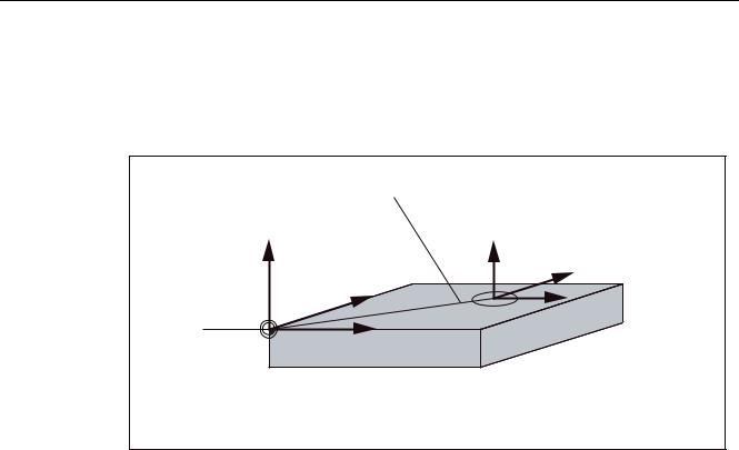
Description
1.5 Coordinate systems
Current workpiece coordinate system
The programmed work offset TRANS can be used to generate an offset with reference to the workpiece coordinate system. resulting in the current workpiece coordinate system (see Section "Programmable work offset: TRANS").
|
3URJUDPPDEOH RIIVHW |
|
|
75$16 |
|
|
= |
|
|
|
FXUUHQW |
= |
|
|
|
|
< |
|
< |
|
|
|
; |
: |
; |
|
: :RUNSLHFH ]HUR
Figure 1-6 Coordinates on the workpiece; current workpiece coordinate system
Milling
Programming and Operating Manual, 11/2012, 6FC5398-0CP10-7BA0 |
19 |

Description
1.5 Coordinate systems
|
Milling |
20 |
Programming and Operating Manual, 11/2012, 6FC5398-0CP10-7BA0 |
Software interface |
2 |
2.1Screen layout
6WDWXV DUHD
$SSOLFDWLRQ DUHD
7LS DQG VRIWNH\ DUHD
Figure 2-1 |
Screen layout |
The screen is divided into the following main areas:
●Status area
●Application area
●Note and softkey area
Status area
|
|
|
|
|
|
Figure 2-2 |
Status area |
Milling |
|
Programming and Operating Manual, 11/2012, 6FC5398-0CP10-7BA0 |
21 |
Software interface
2.1 Screen layout
Table 2- 1 Explanation of the screen controls in the status area
Numbering |
Display |
Icon |
Significance |
|
Active operating area |
|
Position (operating area key <POSITION>) |
|
|
|
|
|
|
|
System (operating area key <SYSTEM>) |
|
|
|
|
|
|
|
Program (operating area key <PROGRAM>) |
|
|
|
|
|
|
|
Program Manager (operating area key |
|
|
|
<PROGRAM MANAGER>) |
|
|
|
|
|
|
|
Parameter (operating area key <OFFSET |
|
|
|
PARAM>) |
|
|
|
|
|
|
|
Alarm (operating area key <ALARM>) |
|
|
|
|
|
Active mode |
|
Approaching a reference point |
|
|
|
|
|
|
|
JOG |
|
|
|
|
|
|
|
JOG INC; 1 INC, 10 INC, 100 INC, 1000 INC, |
|
|
|
VAR INC |
|
|
|
(incremental evaluation in the JOG mode) |
|
|
|
|
|
|
|
MDA |
|
|
|
|
|
Milling |
22 |
Programming and Operating Manual, 11/2012, 6FC5398-0CP10-7BA0 |
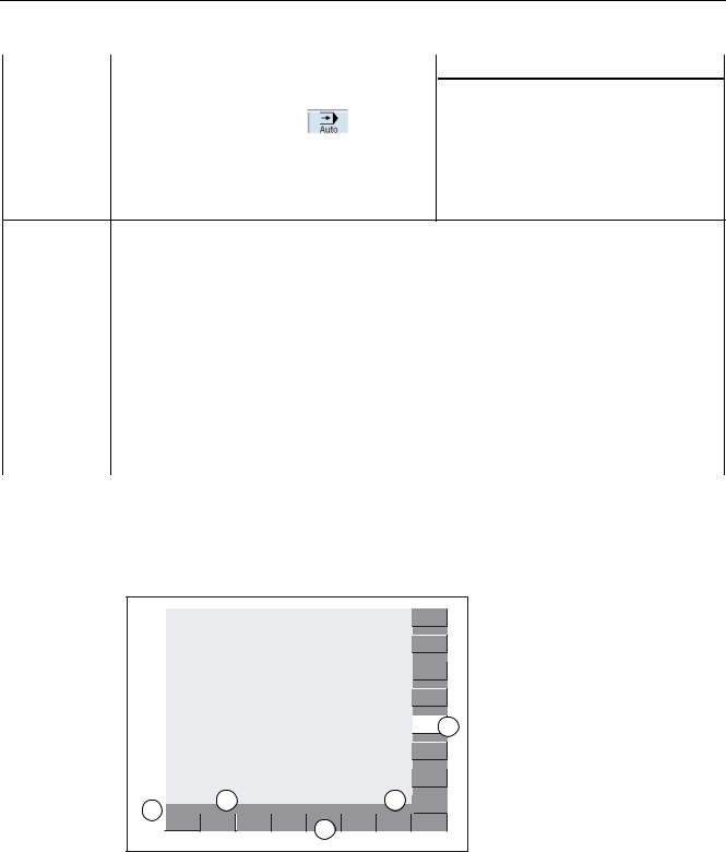
Software interface
2.1 Screen layout
Numbering |
Display |
Icon |
Significance |
|
|
|
AUTOMATIC |
|
|
|
|
|
Alarm and message line |
In addition, the following is displayed: |
|
|
|
1. |
Alarm number with alarm text, or |
|
|
2. |
Message text |
Selected part program (main program)
|
Program state |
RESET |
Program canceled / default state |
|
|
RUN |
Program is running |
|
|
STOP |
Program stopped |
|
Program control in automatic |
SKP |
Skip: Skip block |
|
mode |
DRY |
Dry Run: Dry run feedrate |
|
|
||
|
|
ROV |
Rapid Override: Rapid traverse override |
|
|
M01 |
Conditional stop |
|
|
PRT |
Program test |
|
|
SBL |
Single Block: Single block |
|
Date and time |
|
From version 1.4 SP 6 and higher, the date and |
|
|
|
the time are displayed. |
Note and softkey area

Figure 2-3 Note and softkey area
Milling |
|
Programming and Operating Manual, 11/2012, 6FC5398-0CP10-7BA0 |
23 |

Software interface
2.1 Screen layout
Table 2- 2 Explanation of the screen controls in the note and softkey area
Screen item |
Display |
Significance |
|||||||
|
|
|
|
|
|
|
|
|
RECALL symbol |
|
|
|
|
|
|
|
|
|
Pressing the <RECALL> key lets you return to the higher menu |
|
|
|
|
|
|
|
|
|
level. |
|
|
|
|
|
|
|
|
|
|
|
|
|
|
|
|
|
|
|
Information line |
|
|
|
|
|
|
|
|
|
Displays notes and information for the operator and fault states |
|
|
|
|
|
|
|
|
|
HMI status information |
|
|
|
|
|
|
|
|
|
ETC is possible (pressing this key displays the horizontal |
|
|
|
|
|
|
|
|
|
softkey bar providing further functions.) |
|
|
|
|
|
|
|
|
|
|
|
|
|
|
|
|
|
|
|
Mixed notation active (uppercase/lowercase letters) |
|
|
|
|
|
|
|
|
|
|
|
|
/ |
|
|
|
|
|
|
|
|
|
|
|
|
|
|
|
|
|
|
|
|
|
|
|
|
|
|
RS232 connection active |
|
|
|
|
|
|
|
|
|
|
|
|
|
|
|
|
|
|
|
Connection to commissioning and diagnostic tools (e.g. |
|
|
|
|
|
|
|
|
|
Programming Tool 802) active |
|
|
|
|
|
|
|
|
|
|
|
|
|
|
|
|
|
|
|
|
|
|
|
|
|
|
|
|
|
|
|
|
|
|
|
|
|
|
|
RCS network connection active |
|
|
|
|
|
|
|
|
|
|
|
|
|
|
|
|
|
|
|
Softkey bar vertical and horizontal |
Display of the softkeys in the document
To make the softkeys easier to locate, the horizontal and vertical softkeys are displayed in different basic colors.
Horizontal softkey
Vertical softkey
|
Milling |
24 |
Programming and Operating Manual, 11/2012, 6FC5398-0CP10-7BA0 |

Software interface
2.2 Standard softkeys
2.2Standard softkeys
%DFN
;
$ERUW
$FFHSW
8VHU IXQFWLRQ
Use this softkey to close the screen.
Use this softkey to cancel the input; the window is closed.
Selecting this softkey will complete your input and start the calculation.
Selecting this softkey will complete your input and accept the values you have entered.
User-specific functions are called in the operating areas <POSITION>, <OFFSET PARAMETER> and <SYSTEM>. The softkey is only visible if the machine manufacturer saved special functions.
Refer to the following documentation for softkey activation: Operating Instructions, SINUMERIK 802D sl Turning, Milling, Grinding, Chapter: Activating "User function" softkey.
Milling |
|
Programming and Operating Manual, 11/2012, 6FC5398-0CP10-7BA0 |
25 |
Software interface
2.3 Operating areas
2.3Operating areas
The functions of the control system can be carried out in the following operating areas:
|
|
POSITION |
Machine operation |
|
|
||
|
|
|
|
|
|
|
|
|
|
|
|
2))6(7 3$5$0
6<67(0

$/$50
6<67(0
$/$50
OFFSET PARAM |
Entering the compensation values and setting data |
PROGRAM |
Creation of part programs |
PROGRAM |
Part program directory |
MANAGER |
|
SYSTEM |
Diagnostics, commissioning |
ALARM |
Alarm and message lists |
CUSTOM |
Users can call their own application |
To change to another operating area, press the relevant key on the CNC full keyboard (hard key).
Protection levels
The SINUMERIK 802D sl provides a concept of protection levels for enabling data areas. The control system is delivered with default passwords for the protection levels 1 to 3.
Protection level 1 |
Experts password |
Protection level 2 |
Manufacturer password |
Protection level 3 |
User password |
These control the various access rigths.
|
Milling |
26 |
Programming and Operating Manual, 11/2012, 6FC5398-0CP10-7BA0 |
Software interface
2.4 The help system
In the menus listed below the input and modification of data depends on the protection level set:
●Tool offsets
●Work offsets
●Setting data
●RS232 settings
●Program creation / program correction
2.4The help system
Comprehensive online help is stored in the control system. Some help topics are:
●Product brief of all important operating functions
●Overview and product brief of the NC commands
●Explanation of the drive parameters
●Explanation of the drive alarms
Operating sequence
You can call the help system from any operating area either by pressing the Info key or by using the key combination <ALT+H>.
Figure 2-4 Help system: Table of contents
Milling |
|
Programming and Operating Manual, 11/2012, 6FC5398-0CP10-7BA0 |
27 |
Software interface
2.4 The help system
Softkeys
|
This function opens the selected topic. |
6KRZ |
|
|
|
Figure 2-5 Help system: Description of the topic
*R WR 7RSLF
%DFN WR 7RSLF
)LQG
Use this function to select cross references. A cross reference is marked by the characters ">>....<<". This softkey is only displayed if a cross reference is displayed in the application area.
If you select a cross-reference, the "Back to topic" softkey will also be displayed. Select this function to go back to the previous screen.
Use this function to search for a term in the table of contents. Type the term you are looking for and start the search process.
Help in the "Program editor" area
The help system offers an explanation for each NC operation. To display the infotext directly, position the cursor after the appropriate operation and press the Info key. The NC instruction must be written using uppercase letters.
|
Milling |
28 |
Programming and Operating Manual, 11/2012, 6FC5398-0CP10-7BA0 |
Turning On, Reference Point Approach |
3 |
3.1Turning on and approaching reference points
Note
When you turn on the SINUMERIK 802D sl and the machine, please also observe the machine documentation, since turning on and reference point approach are machinedependent functions.
Operating sequence
First, switch on the power supply for the CNC and the machine.
After the control system has booted, you are in the "Position" operating area, in the "Reference point approach" mode.
The "Reference point" window is active.
Figure 3-1 Reference-point approach start screen
The "Reference point" window displays whether the axes are referenced.
$[LV PXVW EH UHIHUHQFHG
$[LV LV UHIHUHQFHG V\QFKURQL]HG
Milling |
|
Programming and Operating Manual, 11/2012, 6FC5398-0CP10-7BA0 |
29 |

Turning On, Reference Point Approach
3.1 Turning on and approaching reference points
;
<
=
Press the arrow keys.
If you select the wrong approach direction, no motion is carried out.
One after the other, move each axis to the reference point.
You can exit the function by selecting another operating mode (MDA, AUTOMATIC or JOG). To access the functions described below, you need to select "Jog" mode.
|
Milling |
30 |
Programming and Operating Manual, 11/2012, 6FC5398-0CP10-7BA0 |
Loading...