

/
A2 A1 A3 A
DELTA reflex
Siemens AG
P.O. Box 10 09 53
G205031
93009 Regensburg
07
0786-CPD-20419
EN 14604
2005
Rauchmelder Batterie, titanweiß 5TC1 290
Smoke detector battery,
titanium white
Rauchmelder Batterie,
5TC1 293
aluminiummetallic
Smoke detector battery,
aluminium metallic
Rauchmelder Batterie, tabak 5TC1 294
Smoke detector battery, tobacco
Bedien- und Montageanleitung
Operating and mounting instructions
Stand: Januar 2008
Issue:
January 2008
A
4
Do not paint
Produkt- und Funktionsbeschreibung Product and Applications Description
Der DELTA reflex Rauchmelder Batterie (VdS) ist für den
Einsatz im privaten Wohnbereich konzipiert. Der Rauchmelder
erkennt frühzeitig den bei Bränden entstehenden Rauch und
gibt Alarm. Neben dem Einzelbetrieb können bis zu 40
Rauchmelder gleichen Fabrikats per zweiadriger Leitung
vernetzt werden.
Zusätzlich besteht die Möglichkeit den Rauchmelder mit einem
steckbaren Rauchmeldermodul Relais für externe Alarmgeber
(z.B. Hupe, Blinklicht) oder einem steckbaren Rauchmeldermodul wave uni für Funkübertragung (GAMMA wave)
auszustatten.
HINWEIS:
Die genaue Funktionalität bei Verwendung des Relais- oder
Funkmoduls kann der entsprechenden Bedien- und
Montageanleitung entnommen werden.
Der DELTA reflex Rauchmelder Batterie ist in den Farben
titanweiß (ähnlich RAL 9010), aluminiummetallic (ähnlich RAL
9006) und tabak (ähnlich RAL 8019) erhältlich.
Blatt 1 von 4, 251653.41.03 " DS 0 9"
Die Funktion des Rauchmelders basiert auf dem photoelektrischen Streulichtprinzip ohne radioaktive Präparate. In der
Messkammer des Rauchmelders sind ein Infrarotsender und empfänger (Fotozelle) so angeordnet, dass das ausgestrahlte
Lichtsignal des Senders nic ht direkt auf den Empfänge r treffen
kann. Der bei einem Brand entstehende Rauch dringt in die
Messkammer ein und streut das von dem Sender ausgestrahlte
Lichtsignal. Durch die Streuung treffen die Lichtstrahlen auf den
Lichtempfänger (Fotozelle) und werden dort in ein elektrisches
Signal umgewandelt, welches die optische (blinkendes
Lichtsignal) und akustische (pulsierender Signalton, 85dB(A))
Alarmierung auslöst.
Die Rücksetzung des Alarms erfolgt entweder automatisch,
wenn der Rauch aus der Messkammer vollständig entwichen ist
oder wenn die Alarm- /Quittiertaste bis zum Druckpunkt betätigt
wurde.
Die Funktionskontrolle des Rauchmelders, z.B. auf allmähliche
Verschmutzung (Staubablagerung), erfolgt ebenfalls durch die
Betätigung der Alarm-/Quittiertaste. Bei korrekter Funktion wird
ein kurzes akustisches Signal abgegeben und die Leuchtdiode
blinkt 10 mal. Eventuelle Störungen werden ausschließlich
optisch durch ein dauerhaft blinkendes Lichtsignal angezeig t.
Die Spannungsversorgung des Rauchmelders wird durch
handelsübliche Batterien (3x1,5V LR6, Alkaline Mignon, AA)
sichergestellt. Die typische Batterielebensdauer des
Rauchmelders beträgt ohne Alarmierung 5 Jahre. Dies gilt auch
bei gestecktem Relais- oder Funkmodul. Sinkt die
Batteriespannung unter ein Mindestniveau, so meldet der
Rauchmelder zyklisch durch ein optisches und akustisches
Signal (kurzer Signalton) mindestens 30 Tage lang, dass die
Batterien gewechselt werden müssen. Während dieser Zeit ist
der Rauchmelder auch mit gesteckten Modulen voll
funktionsfähig.
Um die Funktion des Rauchmelders sicherzustellen, ist eine
Montage des Melders ohne eingelegte Batterien nicht möglich
(Batteriefachkontrolle). Ferner wird durch den Verpolungsschutz
bei falsch eingelegten Batterien eine Zerstörung des
Rauchmelders verhindert.
Produkt- und Funktionseigenschaften
• VdS zertifiziert
• batteriebetriebener Rauchmelder für den Wohnbereich,
basierend auf dem photoelektrischen Streulichtprinzip
• lange Batterielebensdauer: typisch 5 Jahre
• vernetzbar: bis zu 40 Rauchmeldern gleichen Fabrikats
• Funktionserweiterung über steckbare Module:
- Rauchmeldermodul Relais 5TC1 291
- Rauchmeldermodul wave uni 5WG3 255-8AB01
• Rauchmelder verfügbar in den Farben:
- titanweiß 5TC1 290
- aluminiummetallic 5TC1 293
- tabak 5TC1 294
• optische und akustische Alarmierung
• Funktionstest und Verschmutzungs- /Störungsanzeige
mittels Alarm- /Quittiertaste
• Batteriewechselanzeige
• Batteriefachkontrolle
• Verpolungsschutz bei falsch eingelegten Batterien
Bedienung, Betriebs- und Alarmsignale Operation, operational signals and alarm signals
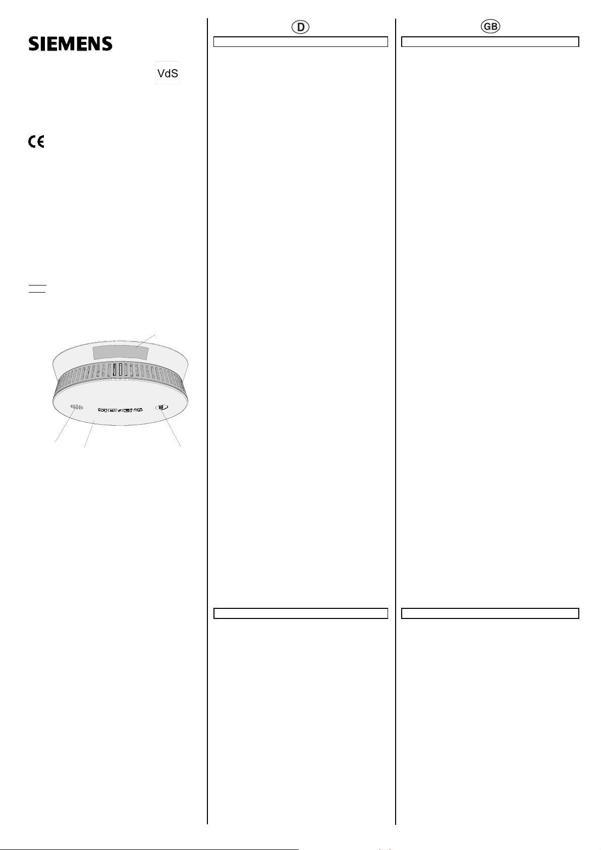
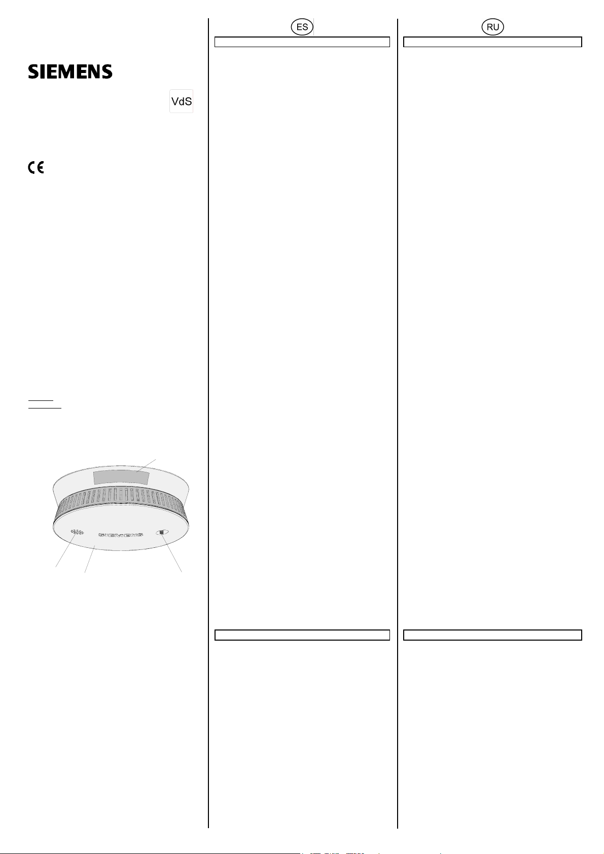
Bild A
A1 Rauchmelder Batterie
A2 Alarm- /Quittiertaste mit optischer Anzeige (Leuchtdiode)
A3 akustischer Signalgeber
A4 Aufkleber “Nicht überstreichen“
Die Bedienung des Rauchmelders erfolgt ausschließlich über
die Alarm- /Quittiertaste (A2). Diese dient entweder zur Funktionskontrolle des Rauchmelders (A1) z.B. auf allmähliche
Verschmutzung (Staubablagerung) oder wird zur Quittierung
des Rauchalarms benötigt. Zudem beinhaltet die AlarmQuittiertaste auch die optische Anzeige (Leuchtdiode A2) für die
Betriebs- und Alarmsignale. Die akustische Alarmierung
(Signalton) erfolgt über den Signalgeber (A3).
The DELTA reflex smoke detector Battery (VdS) has been
designed for use in the private residential sector. In the event of
a fire, the smoke detector detects the development of smoke in
good time and issues an alarm. In addition to stand-alone
operation, up to 40 smoke detectors of the same make can be
networked together via a twin-core cable.
It is also possible to fit the smoke detector with a plug-in smoke
detector module relay for external signalling devices (e.g. h orn,
strobe light) or a plug-in smoke detector module wave uni for
radio transmission (GAMMA wave).
NOTE:
The exact functionality when using the relay module or radio
module can be taken from the corresponding operating and
mounting instructions.
The DELTA reflex smoke detector battery is available in the
colours titanium white (similar to RAL 9010), aluminium metallic
(similar to RAL 9006) and tobacco (similar to RAL 8019).
The function of the smoke detector is based on the photoelectric
scattered light principle without radioactive preparations. An
infrared transmitter and receiver (photocell) are arranged in the
measuring chamber of the smoke detector so that the emitted
light signal of the transmitter cannot directly hit the receiver. The
smoke originating from a fire penetrates the measuring chamber
and scatters the light signal emitted by the transmitter. Due to the
dispersion, the beams of light hit the light receiver (photocell) and
are converted into an electrical signal which triggers the optical
(flashing light signal) and acoustic (pulsating signal tone,
85dB(A)) alarms.
The reset of the alarm is either carried out automatically when
the smoke has completely escaped the measuring chamber or if
the alarm/acknowledgement button has been pressed.
The functional check of the smoke detector e.g. for gradual
pollution (dust deposits) is likewise carried out by pressing the
alarm/acknowledgement button. If the function is correct, a short
acoustic signal is issued and the LED flashes 10 times. Any
possible faults are displayed visually by the continual flashing of
a light signal.
The power supply of the smoke detector is ensured by
conventional batteries (3x1.5V LR6, miniature Alkaline, AA). The
typical battery service life of the smoke detector is 5 years
without alarms. This also applies when the relay module or radio
module is connected. If the battery voltage drops below a
minimum level, the smoke detector reports that the batteries
must be changed by sending a cyclical optical and acoustic
signal (short signal tone) for at least 30 days. During this period,
the smoke detector is also fully functional even with the modules
connected.
To guarantee the function of the smoke detector, it is not
possible to install the detector without the batteries being
inserted (battery compartment check). The reverse voltage
protection also prevents the smoke detector from beingdamaged
if the batteries are incorrectly inserted.
Product and functional characteristics
• VdS approval
• Battery-operated smoke detector for the residential sector,
based on the photoelectric scattered light principle
• Long battery service life: typically 5 years
• Can be networked: up to 40 smoke detectors of the same make
• Functional extension via plug-in modules:
- Smoke detector module relay 5TC1 291
- Smoke detector module wave uni 5WG3 255-8AB01
• Smoke detector available in the colours:
- titanium white 5TC1 290
- aluminium metallic 5TC1 293
- tobacco 5TC1 294
• Optical and acoustic alarms
• Functional test and pollution/fault display using
alarm/acknowledgement button
• Display for battery replacement
• Battery compartment check
• Reverse voltage protection when batteries are incorrectly
inserted
Diagram A
A1 Smoke detector battery
A2 Alarm/acknowledgement button with visual display (LED)
A3 Acoustic signalling device
A4 “Do not paint” sticker
The operation of the smoke detector is carried out solely via the
alarm/acknowledgement button (A2). This is used either for the
functional check of the smoke detector (A1) e.g. for gradual
pollution (dust deposits) or required to acknowledge the smoke
alarm. The alarm/acknowledgement button also contains the
visual display (LED A2) for the operational and alarm signals.
The acoustic alarm (signal tone) is carried out via the signalling
device (A3).
251653.41.03 "DS09 " Seite 1 von 4 Page 1 of 4
Bedienung, Betriebs- und Alarmsignale
Blinkimpuls ca.
im 48 s - Takt
10 mal kurz
blinkt ca. im
blinkt ca. im
Blinkimpuls
ca. im 48 s -
pulse ca. im
1 s - Takt
1 s - Takt
3 Blinkim-
48 s - Takt
Signal
optisch akustisch
blinkt
Signaltöne ca.
im 4 s - Takt
Takt
Signaltöne ca.
im 4 s - Takt
Signalton ca. im
48 s - Takt
--
kurzer
Signalton
--
3 kurze
3 kurze
kurzer
normale Funktion
(Überwachung)
Rauchalarm
Empfangener
Rauchalarm (bei
Vernetzung)
Meldung Batterie
schwach (30 Tage)
Zustand
Test
O.K.
Test
nicht O.K.
(lokal)
Signale nach Alarmquittierung
blinkt ca. im
1 s - Takt
Blinkimpuls
ca. im 48 s -
B
B1
B4
B3
B2
blinkt ca. im
1 s - Takt
Blinkimpuls
ca. im 48 s -
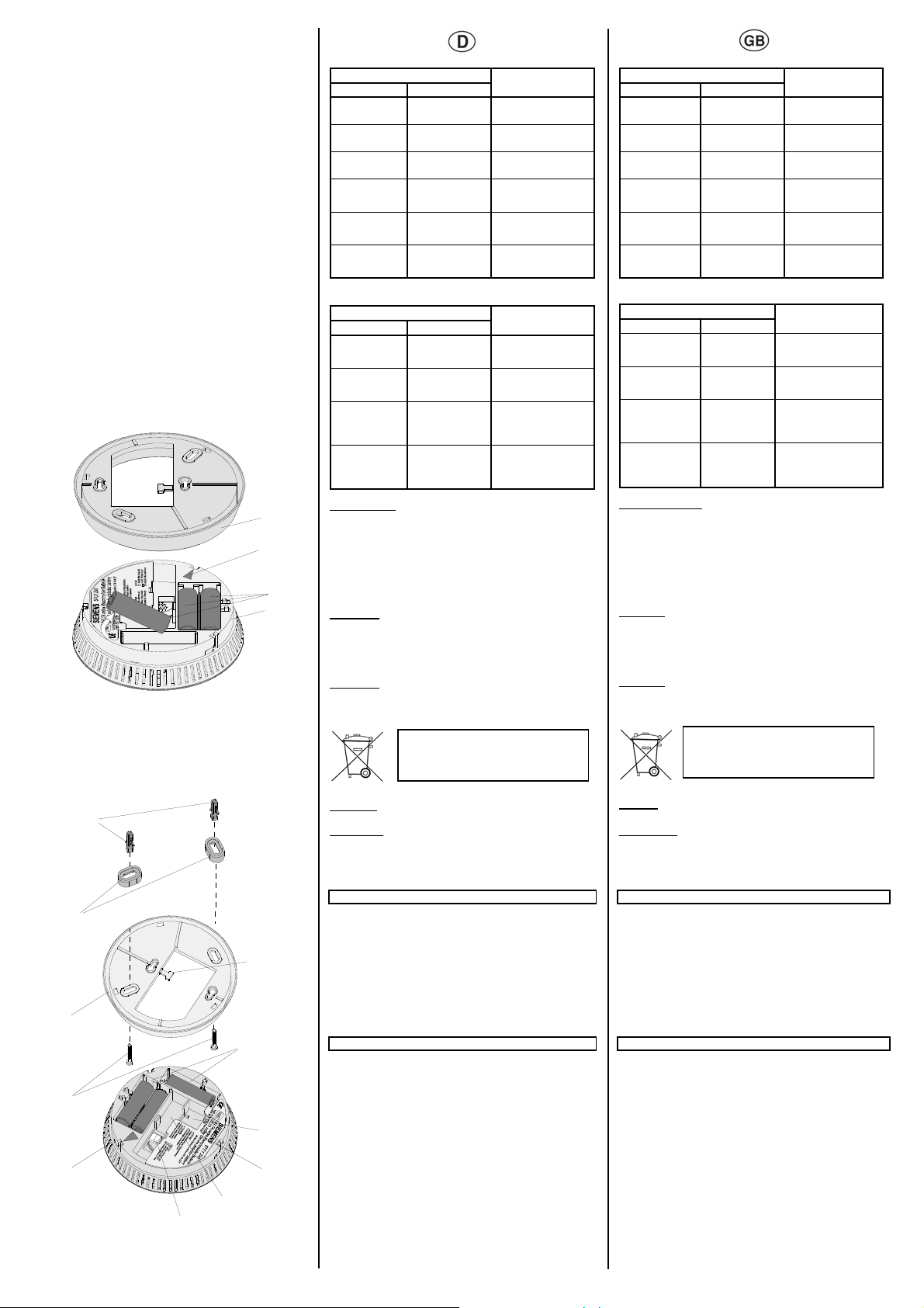
Batteriewechsel Bild B
Wird die Untergrenze der Batteriespannung erreicht bzw.
unterschritten, so wird dies akustisch und optisch angezeigt
(siehe Tabelle Betriebs- und Alarmsignale).
1. Das aus zwei Teilen bestehende Gerät (Sockel B1 und
Rauchmelder B2) durch eine Drehbewegung gegen den
Uhrzeigersinn (Bajonett-Verschluss) öffnen.
2. Die Batterien (B3) aus den Batteriefächern entnehmen.
3. Die drei neuen Batterien richtig gepolt einlegen.
ACHTUNG:
Es dürfen nur Batterien des Typs 1,5V LR6, Alkaline Mignon,
AA verwendet werden.
4. Rauchmelder in den Sockel einführen und durch Drehbewegung im Uhrzeigersinn verrasten. Als Orientierung dienen
die roten Dreiecke (B4/E4).
ACHTUNG:
Nur mit eingelegten Batterien lässt sich der Rauchmelder im
Sockel fixieren.
5. Führen Sie den Funktionstest durch (siehe Seite 4).
C
Wartung und Pflege
C1
C2
C11
C3
C10
C4
C9
C5
C6
251653.41.03 "DS09 " Seite 2 von 4 Page 2 of 4
C8
C7
Monatlich:
einen Funktionstest durchführen (siehe Seite 4).
Halbjährlich:
Gelegentlich sollte der Rauchmelder außen gereinigt werden,
z.B. mit einem leicht ang efeuc htete n Tuch.
Der Geräteaustausch wird nach 10 Jahren empfohlen.
Aufbau des Rauchmelders
Bild C
C1 Dübel
C2 Abstandshalter
C3 Sockel
C4 Schrauben
C5 Rauchmelder
C6 Steckklemme für Drahtvernetzung
C7 Stauraum für Leitungsgut
C8 Modulabdeckung
C9 Steckplatz für Funk- oder Relaismodul
C10 Batteriefächer incl. Batterien
C11 Befestigung für Kabelbinder
Technische Daten
Spannungsversorgung
• erfolgt über Batterien 3x1,5V LR6, Alkaline Mignon, AA
• Batterielebensdauer: typisch 5 Jahre (ohne Alarmierung)
• Meldung Batterie schwach: alle 48s drei kurze Blink-Impulse
und kurzer akustischer Signalton
Ansprechempfindlichkeit
EN 14604 2005
Signalisierung
• akustischer Signalgeber: > 85dB(A) in 3m Abstand
• optische Anzeige: Leuchtdiode rot
Vernetzung:
• bis zu 40 Rauchmelder mit einer zweiadrigen,
verdrillten Leitung z.B. Typ. J-Y(St)Y 2x2x0,6mm
• Gesamtleitungslänge: max. 400m
Signal
optisch akustisch
Signalton AUS
Takt
Takt
Signalton AUS
3 kurze
Signaltöne ca.
im 4 s - Takt
Signalton AUS
Die verbrauchten Batterien sind
entsprechend den geltenden Vorschriften zu entsorgen
Zustand
Alarmquittierung bei
empfangene Alarm-
Raum (Vernetzung)
lokale
Rauch im Raum
lokale Alarmquittierung ohne
Rauch im Raum
quittierung bei
Rauch im Raum
(Vernetzung)
empfangene
Alarmquittierung
ohne Rauch im
Operation, operational signals and alarm signals
flashing pulse
appr. in 48 s cycle
flashes briefly
flashes in appr.
flashes in
approx. 1 s
flashing pulse
in approx. 48 s
3 flashing pulses in approx.
48 s cycle
Signals after alarm acknowledgement
flashes in
approx. 1s
flashing pulse
in approx. 48 s
flashes in
approx. 1 s
flashing pulse
in approx. 48 s
Battery replacement
If battery voltage reaches or falls below the lower limit, this is
displayed both visually and acoustically (see table of operational
signals and alarm signals).
1. Open the device consisting of two parts (base B1 and smoke
detector B2) by turning it anti-clockwise (bayonet lock).
2. Remove the batteries (B3) from the battery compartments.
3. Insert the three new batteries with the correct polarity.
CAUTION:
Only batteries of the type 1.5V LR6, miniature Alkaline, AA
should be used.
4. Insert the smoke detector in the base and lock in place by
turning it clockwise. The red triangles are used for orientation
(B4/E4).
CAUTION:
The smoke detector can only be fixed in the base when the
batteries have been inserted.
5. Carry out the functional test (see page 4).
Service and maintenance
Monthly:
Carry out a functional test (see page 4).
Twice a year:
The outside of the smoke detector should b e cleaned oc casion ally e.g.
with a slightly damp cloth.
A replacement of th e sm oke detec tor i s rec omm ende d aft er 1 0 year s.
Structure of the smoke detector
Diagram C
C1 Plug
C2 Spacer
C3 Base
C4 Screw
C5 Smoke detector
C6 Plug-in terminal for wire connection
C7 Storage space for cables
C8 Module cover
C9 Module location for radio module or relay module
C10 battery compartments incl. batteries
C11 Fixing for cable ties
Technical Specifications
Power supply
• Carried out via batteries 3x1.5V LR6, miniature Alkaline, AA
• Battery service life: typically 5 years (without alarms)
• Battery low signal: three short flashing pulses every 48s and
short acoustic signal tone
Sensitivity
EN 14604 2005
Signalling
• Acoustic signalling device: > 85dB(A) at distance of 3m
• Visual display: red LED.
Networking:
• Up to 40 smoke detectors with a twin-core, twisted cable
e.g. type J-Y(St)Y 2x2x0.6mm
• Total cable length: max. 400m
Signal
optical acoustic
10 times
1 s cycle
cycle
cycle
optical acoustic
cycle
cycle
cycle
cycle
short signal
3 short signal
tones in approx.
3 short signal
tones in approx.
short signal
tone in approx.
48 s cycle
Signal
signal tone
signal tone
3 short signal
tones in
approx. 4s
signal tone
Diagram B
The exhausted batteries must be
disposed of in accordance with the
appropriate regulations
--
tone
--
4 s cycle
4 s cycle
OFF
OFF
cycle
OFF
Status
normal function
(monitoring)
test
O.K.
test
not O.K.
smoke alarm
(local)
received smoke
alarm (for
networking)
signals that battery
is weak
(30 days)
Status
local alarm
acknowledgement
with smoke in room
local alarm
acknowledgement
with smoke in room
received alarm
acknowledgement
with smoke in room
(for networking)
received alarm
acknowledgement
without smoke in
room (for networking)
VORSICHT:
Es dürfen nur DELTA reflex Rauchmelder Batterie (5TC1 290,
5TC1 293, 5TC1 294) miteinander vernetzt werden.
• Zusätzlich erweiterbar mit steckbaren Modulen:
Rauchmeldermodul Relais
- Schaltspannung: max. 30V DC / 42V AC
- Schaltstrom: max. 1A DC / 0,5A AC
Rauchmeldermodul wave uni
- Funkfrequenz: 868MHz
- Reichweite im Freifeld: ca. 100m
Mechanische Daten:
• Gehäuse: Kunststoff (ABS,ASA)
• Gehäusemaße (∅ x H): 120 x 44mm
• Gewicht (ohne Batterie): 148g
• Montage: Aufputz mit oder ohne Abstandshalter
Elektrische Sicherheit
Schutzart (nach EN 60529): IP30
EMV – Anforderung
EN 50130-4, EN 61000-6-3
Umweltbedingungen
• Umgebungstemperatur in Betrieb: 0 bis + 50°C
• Lagertemperatur: -25 bis +70°C
• Rel. Feuchte (nicht kondensierend): 5% bis 93%
Approbation: VdS-Anerkennung: G205031
CE-Kennzeichnung
EMV- Richtlinie 2004/108/EG
Bauproduktenrichtlinie 89/106/EWG, 0786-CPD-20419
Installationshinweise
HINWEIS:
• Ein Rauchmelder detektiert Rauch, nicht aber das Feuer
oder die entstehende Hitze.
• Ein Rauchmelder überwacht nur einen bestimmten Bereich.
Um das ganze Haus (Wohnung) abzudecken, sind
ausreichend Melder zu montieren und gegebenenfalls zu
vernetzen.
• Zusätzliche Sicherheit bieten steckbare Zusatzmodule z.B.
zum Ansteuern einer Hupe, einer Signalleuchte oder eines
Telefonwählgerätes.
• Vor Einsetzen der Batterien und dem Funktionstest sollte der
Rauchmelder in etwa die Temperatur des Montageortes
angenommen haben, um eine Betauung in der
Rauchkammer und damit eine Fehlfunktion zu vermeiden.
• Das Gerät darf nur für feste Installationen in trockenen
• Der Rauchmelder darf nur mit Rauchmeldern gleichen
• Den Rauchmelder nicht bekleben oder mit Farbe
• Der Rauchmelder arbeitet nur mit den vorgeschriebenen
D
251653.41.03 "DS09 " Seite 3 von 4 Page 3 of 4
• Beim Funktionstest ist ein Sicherheitsabstand von
Montage und Verdrahtung
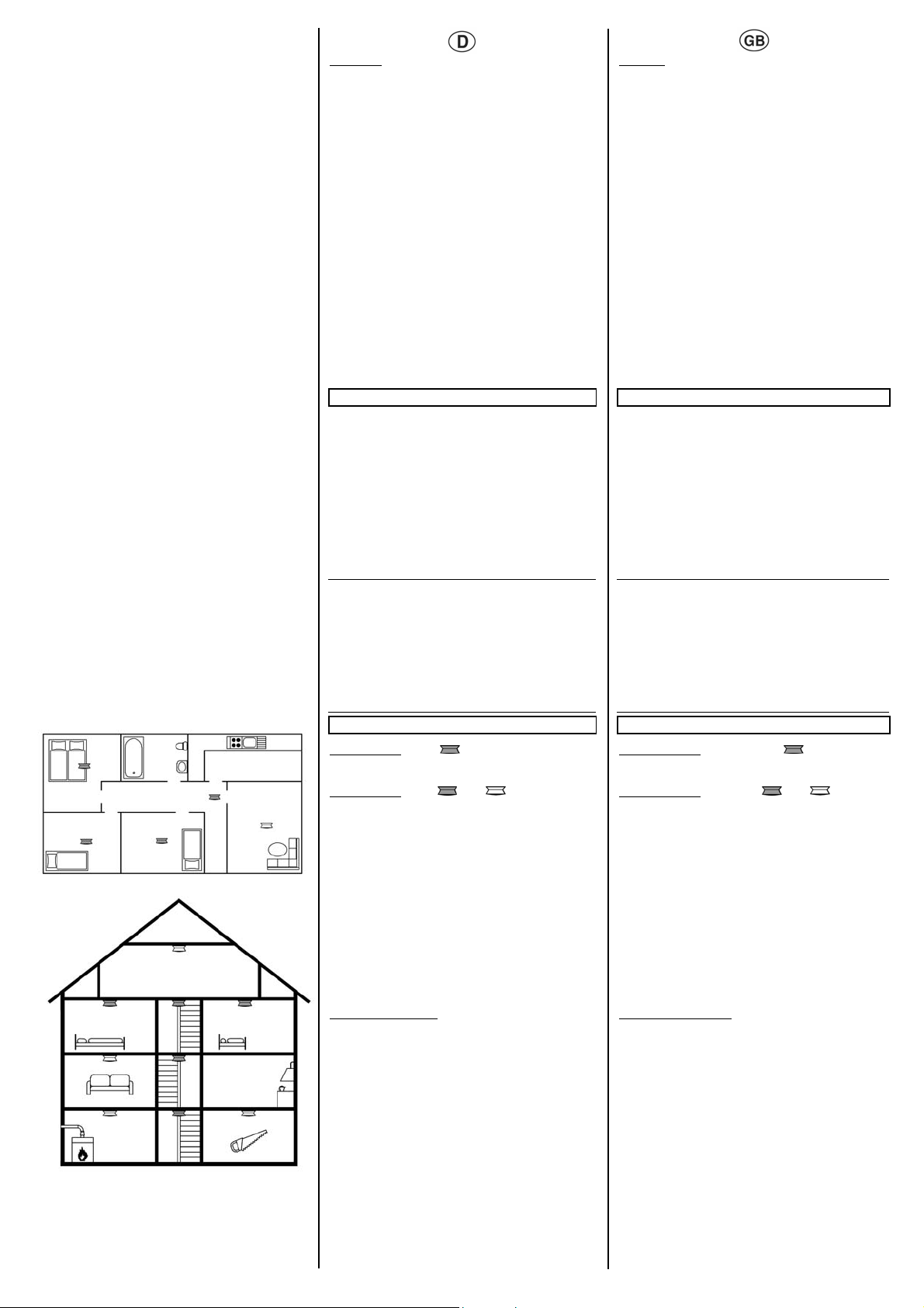
Montageort
Minimaler Schutz Bild D
• Pro Etage, vorzugsweise im Flur und zusätzlich in jedem
Optimaler Schutz Bild D +
• In jedem Wohn- und Schlafraum sowie im Flur sind
• Um sicher zu gehen, dass möglichst früh und in vielen
HINWEIS:
• Jeder Rauchmelder kann eine Fläche von maximal 60m²
• Rauchmelder möglichst in der Deckenmitte anordnen. Ist
• In Räumen mit Schräg-, Spitz- oder Giebeldecke den
• Bei Räumen mit mehr als 3m Höhe sind mehrere Geräte
• Bei der Montageposition sind typische, von den individuellen
Ungeeignete Montageorte
Aus Gründen der Sicherheit und um Fehlalarme und
Fehlfunktionen zu vermeiden, sollten Rauchmelder nicht an
nachfolgend genannten Orten montiert werden:
• In Räumen, in denen starker Wasserdampf, Staub oder
• In Räumen mit Feuerstätten und offenen Kaminen.
• In der Nähe von elektrischen Feldern (z. B. Leuchtstoff-,
• An Orten, an denen Umgebungstemperaturen von unter 0°C
Montage Bild E (siehe nächste Seite)
1. Das aus zwei Teilen bestehende Gerät (Sockel E3 und
2. Den mitgelieferten Aufkleber (E9) „Nicht überstreichen“
HINWEIS:
Den Rauchmelder so montieren, dass beim Betreten des
Raumes die Leuchtdiode gut sichtbar ist. Der deckungsgleiche
SIEMENS-Schriftzug (E7) auf dem Rauchmelder (E6) und
GEFAHR
U
Innenräumen verwendet werden.
Fabrikats vernetzt werden.
überstreichen.
alkalinen Batterien korrekt. Keine Akkus oder Netzgeräte
verwenden.
mindestens 50cm einzuhalten, um Gehörschäden durch den
Alarmton zu vermeiden.
Schlafraum sind Rauchmelder zu installieren.
Rauchmelder zu installieren.
Räumen über einen entstehenden Brand informiert wird,
sollten alle Rauchmelder vernetzt werden.
überwachen.
dies nicht möglich, einen Mindestabstand von 15cm von
Wand und Ecke einhalten.
Rauchmelder ca. 90cm vom höchsten Punkt der Decke
anordnen.
erforderlich (Montagehöhe an der Wand: 2,5m).
Gegebenheiten abhängige, Luftströmungen zu
berücksichtigen.
Rauch entsteht z.B. Küche oder Bad.
Energiesparlampen und Verkabelung; Mindestabstand: 50cm).
bzw. über +50°C herrschen.
Rauchmelder E6) durch eine Drehbewegung gegen den
Uhrzeigersinn (Bajonett-Verschluss) öffnen.
außen auf den Sockel kleben.
CAUTION:
Only DELTA reflex smoke detectors battery (5TC1 290, 5TC1
293, 5TC1 294) may be linked together.
• Can also be extended with plug-in modules:
Smoke detector module relay
- Switching voltage: max. 30V DC / 42V AC
- Switching current: max. 1A DC / 0.5A AC
Smoke detector module wave uni
- Funkfrequenz: 868MHz
- Reichweite im Freifeld: ca. 100m
Mechanical data
• Housing: plastic (ABS, ASA)
• Housing dimensions (∅ x H): 120 x 44mm
• Weight (without battery): 148g
• Installation: surface-mounted with or without spacer
Electrical safety
Type of protection (in acc. with EN 60529): IP30
EMC requirement
EN 50130-4, EN 61000- 6-3
Environmental conditions
• Ambient operating temperature: 0 to + 50°C
• Storage temperature: -25 to +70°C
• Relative humidity (not condensing): 5% to 93%
Approval: VdS approval: G205031
CE norm
EMC guideline 2004/108/EG
CP-Directive 89/106/EWG, 0786-CPD-20419
Installation Instruction
NOTE:
• A smoke detector detects smoke but not the fire or the heat
generated.
• A smoke detector only monitors a specific area. To cover the
entire house (apartment), sufficient detectors must be
mounted and networked as required.
• Additional safety is offered by plug-in modules e.g. to trigger a
horn, a signal lamp or a telephone dialling device
• Before inserting the batteries and the functional test, the
smoke detector should have approximately the temperature of
the installation site, to avoid condensation in the smoke
chamber and therefore a malfunction.
• The device may only be used for permanent installations in
• The smoke detector may only be networked with smoke
• Do not glue or paint the smoke detector.
• The smoke detector only operates correctly with the stipulated
• During the functional test, a safety distance of at least 50cm
Installation and wiring
Installation site
Minimum protection Diagram D
• Smoke detectors must be installed per floor, preferably in the
Optimum protection Diagram D +
• Smoke detectors must be installed in each living room and
• To ensure that many rooms are informed as early as possible
NOTE:
• Each smoke detector can monitor a maximum area of 60m².
• Smoke detectors should be placed as near to the middle of
• In rooms with slanted, pointed or gabled ceilings, the smoke
• In rooms with a height of more than 3m, several devices are
• When considering the mounting position, typical air currents
Unsuitable installation sites
For reasons of safety and to avoid false alarms and malfunctions,
smoke detectors should not be mounted in the following places:
• In rooms where high levels of steam, dust or smoke are
• In rooms with fireplaces and open chimneys.
• In the vicinity of electrical fields (e.g. fluorescent lamps,
• In places where the ambient temperatures lie below 0°C or
Installation, Diagram E (see next page)
1. Open the device consisting of two parts (base E3 and smoke
2. Fix the supplied sticker (E9) “Do not paint” onto the outside of
NOTE:
Install the smoke detector so that the LED is clearly visible when
entering the room. The SIEMENS inscription (E7) on the smoke
detector (E6) and base (E3) should be used for orientation.
DANGER
U
dry interior rooms.
detectors of the same make.
alkaline batteries. Do not use batteries or mains-operated
devices.
should be maintained in order to avoid ears being damaged
by the alarm tone.
hallway and also in each bedroom.
bedroom as well as in the hallway.
about a fire, all the smoke detectors should be interlinked.
the ceiling as possible. If this is not possible, maintain a
minimum distance of 15cm from the wall and corners.
detector should be placed approx. 90cm from the highest
point of the ceiling.
required (installation height on the wall: 2.5m).
that are dependent on the individual conditions must be taken
into account.
produced, e.g. kitchen or bathroom.
energy-saving lamps and cabling; minimum distance: 50cm).
above +50°C
detector E6) by turning it anti-clockwise (bayonet lock).
the base.
Sockel (E3) ist hierbei als Orientierung zu verwenden.
3. Den Sockel (E3) mit dem beiliegenden Montagematerial
(Schrauben E5 und Dübel E1) an die Decke montier en . Bei
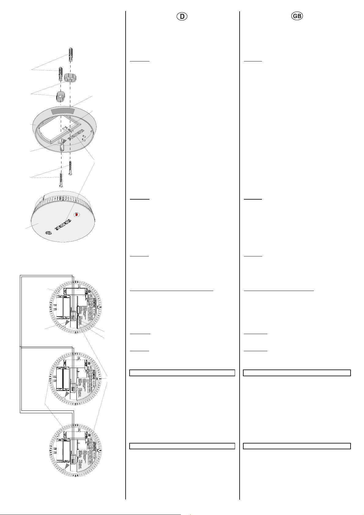
E
E1
E2
Do not paint
E3
E9
E8
E4
E7
E5
E6
F
+
251653.41.03 "DS09 " Seite 4 von 4 Page 4 of 4
F1
-
+
F2
-
-
+
F5
-
+
F4
F3
F6
erhöhtem Platzbedarf Abstandhalter (E2) verwenden. Zum
fixieren von Leitungen oder Rohren ist die Befestigung für
Kabelbinder (E8) zu verwenden.
4. Die drei mitgelieferten Batterien entsprechend der
Polkennzeichnung in die Batteriefächer (C10) einlegen.
ACHTUNG:
Nur mit eingelegten Batterien lässt sich der Rauchmelder im Socke l
fixieren. Um Fehlfunktionen (durch Druckschwankungen bzw.
Zugluft) zu vermeiden, muss die Modulabdeckung montiert sein.
5. Rauchmelder in den Sockel einführen und durch
Drehbewegung im Uhrzeigersinn verrasten. Als Orientierung
dienen die roten Dreiecke (B4/E4).
6. Führen Sie den Funktionstest durch (siehe unten).
Funktionstest:
Nach erfolgter Montage, sowie einmal monatlich, ist die Funktion
jedes Rauchmelders zu prüfen. Dazu ist die Alarm- /Quittiertaste (A2) zu drücken.
• Ertönt die Hupe einmal und blinkt die Leuchtdiode 10 mal, so
arbeitet der Rauchmelder korrekt.
• Fällt der Funktions test negativ aus, be ginnt nur die Leuchtdiode
mit Dauerblinken. Der Rauchmelder ist dann auszutauschen.
• Ertönt weder die Hupe noch blinkt die Leuchtdiode, ist die
Polarität der Batterien zu überp rüfen. Führt dies nicht zum
Erfolg, ist der Rauchmelder ebenfalls auszutauschen.
Vernetzung von Rauchmeldern
Es können bis zu 40 Rauchmelder zusammengeschaltet
werden. Erfasst nun ein Melder Rauch, so ertönt der Alarm
gleichzeitig aus allen miteinander vernetzten Geräten (Bild F).
Die Leuchtdiode blinkt nur an dem Melder, der den Alarm
auslöst. Dadurch kann der auslösende Rauchmelder leicht
ermittelt werden. Die Verbindung der Melder erfolgt mit einer
verdrillten zweiadrigen Leitung (z.B. J-Y(ST)Y 2x2x0,6mm). Die
Gesamtleitungslänge der zusammengeschalteten Rauchmelder
darf 400m nicht überschreiten. Bei falscher Polarität verhindert
ein Verpolschutz eine Beschädigung des Melders.
ACHTUNG:
• Es ist darauf zu achten, dass kein Leitungsgut zwischen die
Abdichtung von Ober- und Unterteil gerät.
• Die Zusammenschaltung darf nur mit Geräten des gleichen
Typs erfolgen, da sonst Fehlfunktionen auftreten können.
• Nach erfolgter Installation ist ein Vernetzungstest sinnvoll.
Hierzu kann ein Rauchalarm (z.B. mit Zigaretten, Aerosol ...)
ausgelöst werden. Die Rücksetzung des Alarms erfolgt
entweder automatisch, wenn der Rauch aus der
Messkammer vollständig entwichen ist oder wenn die Alarm/Quittiertaste bis zum Druckpunkt betätigt wurde.
• Die Leitungsführung der Vernetzung darf nicht eng, parallel
zu den Netz-/SAT- oder anderen Leitungen erfolgen.
Vernetzung Bild F
F1 Rauchmelder Batterie
F2 Vernetzungsklemme
F3 + Anschluss
F4 – Anschluss
F5 weitere vernetzte Rauchmelder Batterie
F6 Modulabdeckung
Vorgehensweise zur Vernetzung der Rauchmelder:
1. Die Vernetzungsklemme (F2) vom Rauchmelder abziehen.
2. Anschlussdrähte abisolieren (ca. 6mm)
3. Die Drähte in die Federkraftklemmen der Vernetzu ngs-
klemme (F2) stecken.
4. Die Vernetzungsklemme auf den Rauchmelder stecken.
5. Führen Sie einen Funktionstest durch (wirkt nur lokal).
Relais- und Funkmodul
Es besteht die Möglichkeit den Rauchmelder mit einem
steckbarem Relais- oder Funkmodul auszustatten.
Relaismodul:
Relais mit potentialfreiem Wechselkontakt zur Ansteuerung von
externen Alarm- und Signalgeräten wie z.B. Hupen, Sirenen,
oder Telefonwählgeräte.
Funkmodul: Alarmweiterleitung per Funk
HINWEIS:
Die genaue Funktionalität bei Verwendung des Relais- oder
Funkmoduls kann den entsprechenden Bedien- und
Montageanleitungen entnommen werden.
Mögliche Brandursachen Possible causes of fire
Um Brände zu verhindern, sollten nachf olgend e Brandurs achen
vermieden werden:
• schadhafte elektrische Leitungen, falsche Verwendung und
Überhitzung von Elektrogeräten
• leicht brennbare Materialien neben sich stark erwärmenden
Elektrogeräten wie Bügeleisen, Toaster und Friteusen
• unbeaufsichtigtes offenes Feuer wie Kerzen, Kamine und
Teelichter
• Rauchen auf der Couch oder im Bett
• Kurzschlüsse durch Standby-Betrieb bei Radio, Fernseher
und Computern
• Überlastung und Überhitzung von Steckdosen durch
Mehrfachstecker
• verschmutzte Dunstabzugshauben mit Fettablagerungen
• mit Feuer spielende Kinder
Allgemeine Hinweise General notes
Ein defektes Gerät ist an die zuständige Geschäftsstelle der
Siemens AG zu senden.
Bei zusätzlichen Fragen zum Produkt wenden Sie sich bitte an
unseren Technical Support:
Die Bedienungsanleitung ist dem Kunden auszuhändigen
+49 (0) 180 50 50-222
℡
+49 (0) 180 50 50-223
www.siemens.com/aut omati on/ serv ice &supp ort
3. Mount the base (E3) on the ceiling using the installation
materials supplied (screws E5 and pin E1). Use the spacer
(E2) for increased space requirements. The bracket for cable
ties (E8) should be used to fix cables or pipes.
4. Insert the three batteries supplied in the battery compartment
(C10) with the correct polarity.
CAUTION:
The smoke detector can only be fixed in the base when the batteries
have been inserted. The module cover must be mounted to avoid
malfunctions (due to fluctu ations in pr essur e or supply air) .
5. Insert the smoke detector in the base and lock in place by
turning it clockwise. The red triangles are used for orientation
(B4/E4).
6. Carry out the functional test (see below).
Functional test:
The function of each smoke detector must be checked after the
installation has been successfully completed as well as once a
month. Therefore press the alarm/acknowledgement button (A2).
• If the horn sounds once and the LED flashes 10 times, the
smoke detector operates correctly.
• If the functional test fails, only the LED starts to flash
continually. The smoke detector should then be replaced.
• If the horn does not sound and the LED does not flash, the
polarity of the batteries must be checked. If this is not
successful, the smoke detector should also be replaced.
Networking of smoke detector
Up to 40 smoke detectors can be connected together. If a
detector now records smoke, the alarm is emitted from all the
interlinked devices at the same time (Diagram F). The LED only
flashes on the detector that triggered the alarm. It is therefore
easy to determine which smoke detector has been triggered. The
connection of the detectors is carried out with a twisted twin-core
cable (e.g. J-Y(ST)Y 2x2x0.6mm). The total cable length of the
interlinked smoke detectors may not exceed 400m. If the polarity
is incorrect, the reverse voltage protection prevents the detector
from being damaged; an alarm is issued.
CAUTION:
• It should be ensured that there are no cables between the
seal at the top and bottom of the device.
• It is only possible to interconnect devices of the same type as
otherwise malfunctions may occur.
• After a successful installation, it is advisable to carry out a
wiring test. A smoke alarm can be triggered (e.g. with
cigarettes, aerosol …) for this purpose. The alarm is either
reset automatically when the smoke has fully escaped from
the measuring chamber or when the alarm/ acknowledgement
button has been pressed
• The cabeling of the networking may not be laid near, parallel
to the net-/SAT or other wires.
Networking Diagram F
F1 Smoke detector battery
F2 Linking terminal
F3 + connection
F4 – connection
F5 Further linked smoke detectors battery
F6 Module cover
Procedure for networking smoke detectors:
1. Remove the linking terminal (F2) from the smoke detector.
2. Strip the insulation from the connecting wires (appr. 6mm).
3. Insert the wires into the spring-clamp terminals of the linking
terminal (F2).
4. Insert the linking terminal on the smoke detector again.
5. Carry out a functional test (only works locally).
Relay module and radio module
It is possible to fit the smoke detector with a plug-in relay module
or radio module.
Relay Module:
Relay with floating changeover contact for triggering external
alarm and signalling devices such as horns, sirens or telephone
dialling devices.
Radio module: Routing of alarms via radio
NOTE:
The exact functionality when using the relay module or radio
module can be taken from the corresponding operating and
mounting instructions.
To prevent fires, the following causes of fire should be avoided:
• Damaged electrical cables, incorrect usage and overheating
of electrical devices
• Flammable materials next to electrical devices that generate
high levels of heat such as irons, toasters and deep-fat fryers
• Unattended open flames such as candles, chimneys and
tealights
• Smoking on the sofa or in bed
• Short circuits caused by standby operation of radios,
televisions and computers
• Overload and overheating of sockets via multiway adapters
• Dirty extractor hoods with grease deposits
• Children playing with matches
Any faulty devices should be returned to the local Siemens office.
If you have further questions concerning the product, please
contact our technical support:
The operating instruction must be handed over to the client
+49 (0) 180 50 50-222
℡
+49 (0) 180 50 50-223
www.siemens.com/aut omati on/ serv ice &supp ort
Д
Д
Д
A
A2 A1 A
Descripción del producto y del funcionamiento Описание прибора и его функций El detector de humos con batería DELTA reflex (VdS) está
diseñado para el ámbito de la vivienda particular. El detector de
DELTA reflex
Siemens AG
P.O. Box 10 09 53
93009 Regensburg
08
0786-CPD-20419
Detector de humos con batería,
color blanco titanio
Батарея для дымового
извещателя,
цвет титаново-белый
Detector de humos con batería,
aluminio metalizado
Батарея для дымового
извещателя,
цвет алюминиевый
металлический
Detector de humos con batería, 5TC1 294
color tabaco
Батарея для дымового
извещателя, цвет табачный
Instrucciones de uso y de montaje
Руководство по эксплуатации и
монтажу
Situación: Enero 2008
Состояние: Январь 2008 г
G205031
EN 14604
2005
5TC1 290
5TC1 293
A
4
Do not paint
3
humos detecta de forma temprana el humo generado en caso
de incendio y emite una alarma. Además del funcionamiento
individual existe la posibilidad de interconectar hasta 40
detectores de humos de la misma marca con un cable bifilar.
Adicionalmente, existe la posibilidad de equipar el detector de
humos con un módulo de relé de detector de humos enchufable
para emisores de alarma externos (p.ej. bocina, luz de destello)
o un módulo detector de humos enchufable wave uni para la
radiotransmisión (GAMMA wave).
ADVERTENCIA:
La funcionalidad exacta en caso de uso del módulo de relé o de
radio figura en las correspondientes instrucciones de uso y de
montaje.
El detector de humos con batería DELTA reflex está disponible
en los colores blanco titanio (similar a RAL 9010), aluminio
Hoja 1 de 4, 251653.41.03 " D S0 9"
metalizado (similar a RAL 9006) y tabaco (similar a RAL 8019).
El funcionamiento del detector de humos se basa en el principio
fotoeléctrico de dispersión de luz sin preparaciones
radioactivas: en la cámara de medición del detector de humos
están dispuestos un emisor y un receptor de infrarrojos
(fotocélula) de tal modo que la señal luminosa irradiada por el
emisor no puede incidir directamente en el receptor. El humo
generado en caso de incendio penetra en la cámara de
medición y dispersa la señal luminosa irradiada por el emisor.
Como consecuencia de la dispersión, los rayos de luz inciden
en el receptor de luz (fotocélula) donde se convierten en una
señal eléctrica que activa la alarma óptica (señal luminosa
intermitente) y acústica (señal acústica pulsante, 85dB(A)).
El reset de la alarma se realiza automáticamente cuando el humo ha
desaparecido por completo de la cámara de medición o al accionar
la tecla de confirmación de alarma hasta el punto de presión.
El control de funcionamiento del detector de humos, p.ej. con
respecto a un ensuciamiento paulatino (acumulación de polvo)
se realiza igualmente accionando la tecla de confirmación de
alarma. En caso de funcionamiento correcto se emite una breve
señal acústica y el diodo luminoso parpadea 10 veces. Los
eventuales fallos se indican únicamente de forma óptica a
través de un parpadeo continuo de la señal luminosa.
La alimentación eléctrica del detector de humos se asegura con
pilas convencionales (3x1,5V LR6, alcalinas, tamaño AA). La
vida útil típica de las baterías del detector de humos sin alarma
es de 5 años. Lo mismo se aplica con el módulo de relé o de
radio acoplado. Si la tensión de batería desciende por debajo
de un nivel mínimo, el detector de humos señaliza de forma
cíclica mediante una señal óptica y acústica (señal acústica
corta) durante mín. 30 días la necesidad de cambiar las pilas.
Durante este tiempo, el detector de humos está totalmente
operacional, incluso con los módulos acoplados.
Para asegurar el funcionamiento del detector de humos, no es
posible montar el detector sin pilas insertadas (control del
compartimento de baterías). Asimismo, una protección contra
polaridad inversa evita la destrucción del detector de humos en
caso de colocación incorrecta de las pilas.
Características del producto y de funcionamiento
• con certificado VdS
• Detector de humos con batería para el ámbito doméstico,
basado en el principio fotoeléctrico de dispersión de luz
• Larga vida útil de las pilas: típ. 5 años
• Posibilidad de interconexión de hasta 40 detectores de
humos de la misma marca
• Ampliación de funciones con módulos enchufables:
- Módulo detector de humos de relé 5TC1 291
- Módulo detector de humos wave uni 5WG3 255-8AB01
• Detector de humos disponible en los colores:
- blanco titanio 5TC1 290
- aluminio metalizado 5TC1 293
- tabaco 5TC1 294
• Alarmas ópticas y acústicas
• Prueba de funcionamiento e indicación de suciedad / fallos
mediante tecla de confirmación de alarma
• Indicador de cambio de batería
• Control del compartimento de baterías
• Protección contra polaridad inversa en caso de colocación
incorrecta de las pilas
Manejo, señales de funcionamiento y de alarma Сигнализация в режимах управления, эксплуатации и тревоги Fig. A
A1 Detector de humos con batería
A2 Tecla de confirmación de alarma con indicador óptico (diodo
luminoso)
A3 Emisor de señales acústico
A4 Etiqueta adhesiva “No pintar“
El manejo del detector de humos se realiza únicamente a
través de la tecla de confirmación de alarma (A2). Ésta sirve
para el control del funcionamiento del detector de humos (A1),
p.ej. con respecto a un ensuciamiento paulatino (acumulación
de polvo) o se necesita para confirmar una alarma de humos.
Además, la tecla de confirmación de alarma contiene también la
indicación óptica (diodo luminoso A2) para las señales de
funcionamiento y de alarma. La alarma acústica (señal
acústica) se emite a través del emisor de alarmas (A3).
Батарея DELTA ref lex для дымового извещателя (VdS)
предназначена для использования в частных жилых помещениях.
ымовой извещаетель обеспечивает раннее обнаружение
возникающего при пожаре дыма и подает сигнал тревоги.
Помимо автоном ного режима работы, можно об ъединить в
единую се ть до 40 дымовых извещателей одного типа с
помощью двужильного провода.
ополнительно имеется возможность оснастить дымовой
извещатель втычным релейным модулем для внешних устройств
тревожной сигнализации (звуковой , световой мигающей и т.п.)
или втычным модулем wave uni для радиоканальной передачи
(GAMMA wave).
ПРИМЕЧАНИЕ:
Точную информацию о функциональных возможностях
релейного и радиоканального модулей можно найти в
соответствующей инстр укции по эксплуатации и монтажу.
Батарея DELTA ref lex для дымового извещателя предлагается
следующих цветов: титанов о-белый (напоминает цвет RAL 9010),
алюминиевый металлический (напоминает цвет RAL 9006) и
табачный (напоминает цвет RAL 8019).
Работа дымового извещателя основана на фотоэлектрическом
принципе рассеивания света, не предполагающем
использования радиоактивных вещества: источник и приемник
инфракрасного излучения (фотоэлемент) р асполагаются в
измерительной камере таким образом, что издучаемый
световой сигнал не может попасть напрямую в светоприемник.
Попадая в измерительную камеру, дым от возгорания
рассеивает и злученный исто чником световой сигнал. После
рассеивания световы е лучи попадают в приемник (на
фотоэлемент) и преобразуются там в электрический сигнал,
включающий оптическую (мигающий световой сигнал) и
акустическую (пульсовый звуковой сигнал мощностью 85дБ (A)
системы тревожного оповещения.
Сброс тревоги происходит либо автоматическ и (после полного
улетучивания дыма из измерительной камеры), либо после
нажатия кнопки "Тревога/Сброс" до точки отдачи.
Функциональный тест дымового извещателя, например в связи с
возможностью его п остепенного загрязнения (запыления),
производится также нажатием кнопки "Тревога/Сброс". Если
прибор функционирует правильно, срабатывае т короткий
звуковой сигнал и 10 раз мигает светодиод. Нарушения в работе
прибора визуально проявляются в виде постоянно мигающего
свет о вого сигнала.
Рабочее напряжение, необходимое для нор мальной работы
дымового извещателя, обеспечивают 3 обычные щелочные
батареи "пальчикового" типа с напряжением 1,5 В (1,5V LR 6,
Alkaline Mignon, AA). Срок службы батареи дымового извещате ля
в случае отсутс твия тревог обычно составляет 5 лет. В том числе
при работе с подключенным ре лейным или радиоканальным
модулями В тех случаях, когда напряжение батареи опускается
ниже минимального ур овня, дымовой извещатель
предупреждает о необходимости замены батарей ц иклически
повторяющимися оптическ им и акустическим сигналам и
(короткий звуковой тон) в течение как минимум 30 дней подряд.
В это время извещатель сохраняет полную работоспособность
даже с подключенными к нему дополнительными модулями.
ля обеспечения нормальной работы дымового извещателя он
устроен таким образом, что его невозможно смонтировать без
установленных внутри батарей (Кон троль батарейных отсеков).
Дополнительная система защиты от нарушения полярности
предотвращает выход извещателя из строя в случае
неправильной установки батарей.
Технические и функциональные характеристики изделия
• сертифици ровано VdS
• дымовой извещ атель для жилых помещений с питанием от
батарей,основанный на фотоэлектрическ ом принципе
рассеивания света
• долгий срок службы : обычно 5 лет
• объединение в сеть: до 40 извещателей одного т и па
• расширение функциональных возможностей за счет втычных
модулей:
- релейный модуль для дымового извещателя 5TC1 291
- радиоканальный модуль wave uni 5WG3 255-8AB01
• Дымово й извещатель предлагается следующих цветов:
- титаново-белый 5TC1 290
- алюминиевый металлический 5TC1 293
- табачный 5TC1 294
• оптическая и акустическая тревожная сигн а лизация
• Функциональный тест и индикация загрязненности /
неполадок с помощью кнопки "Тревога/Сброс"
• индикатор необходимости замены батарей
• контроль батарейных отсеков
• защита от нарушения полярности при неправильной
установке батарей
Рисунок A
A1 батарея дымового извещателя
A2 кнопка "Тревога/Сброс " с оптическим индикатором
(светодиодом)
A3 звуковой сигнальный датчик
A4 этикетка "Не закрашивать"
Управление дым овым извещате лем осуществляется
исключительно с помощью кнопки "Трев ога/Сброс" (A2). Она
используется либо для проверки работоспособности
извещателя (A1), наприме р в связи с его постепенным
загрязнением (запылением), либо для сброса режима тревоги.
Кроме того, кнопка "Тревога/Сброс" допо лнена опти ческим
индикатором (светодиодом A2) для режимов эксп луатации и
тревоги. Акусти ческая тревога (зв уковой си гнал) выполняется
сигнальным датчиком (A3).
251653.41.03 "D S 09 " Página 1 de 4 Страница 1 из 4

Д
ру
д
Señales de funcionamiento y de alarma
B
C
Impulso intermitente en
intervalos de aprox. 48
parpadea 10 veces
brevemente
parpadea en intervalos de aprox. 1 s
parpadea en
intervalos de
Impulso intermitente en
intervalos de aprox. 48
3 impulsos inter-
mitentes en intervalos
de aprox. 48 s
Señales tras la confirmación de la alarma
parpadea en
intervalos de
Impulso intermitente
en intervalos de
parpadea en
intervalos de
intermitente en
intervalos de
Cambio de pilas Fig. B
Si se alcanza o se pasa por debajo del límite inferior de tensión
de batería, este hecho se indica por vía acústica y óptica (ver
tabla Señales de funcionamiento y de alarma).
B1
B2
B4
B3
1. Abrir el aparato, compuesto de dos partes (zócalo B1 y
detector de humos B2) con un movimiento giratorio en
sentido antihorario (cierre de bayoneta).
2. Retirar las pilas (B3) de los compartimentos de batería.
3. Insertar las tres pilas nuevas con la polaridad correcta.
ATENCIÓN:
Sólo se deben utilizar pilas del tipo LR6, 1,5V alcalino de
tamaño AA.
4. Introducir el detector de humos en el zócalo y enclavarlo con
seguridad mediante un movimiento giratorio en sentido
horario. Como orientación sirven los triángulos rojos
(B4/E4).
ATENCIÓN:
El detector de humos sólo se puede fijar en el zócalo si las
pilas están insertadas.
5. Realice la prueba de funcionamiento (ver página 4).
Limpieza y mantenimiento
Mensualmente:
realizar una prueba de funcionamiento (ver página 4).
Semestralmente:
se debería realizar ocasionalmente una limpieza del exterior del
detector de humos, p.ej. con un paño ligeramente humedecido.
Se recomienda sustituir el aparato a los 10 años.
Estructura del detector de humos
Fig. C
C1
C2
C11
C3
C10
C4
C9
C5
C6
C8
C7
C1 Taco
C2 Separador
C3 Zócalo
C4 Tornillos
C5 Detector de humos
C6 Borne enchufable para la interconexión
C7 Espacio para cables
C8 Cubierta del módulo
C9 Ranura para módulo de radio o de relé
C10 Compartimentos de batería, incl. pilas
C11 Fijación para cintas de sujeción para cables
Datos técnicos
Alimentación eléctrica
• a través de 3 pilas alcalinas 1,5V LR6, tamaño AA
• Vida útil de las pilas: típ. 5 años (sin alarmas)
• Mensaje Batería baja: cada 48s tres impulsos intermitentes
cortos y una señal acústica corta
Sensibilidad de reacción
EN 14604 2005
Señalización
• Emisor de señales acústico: > 85dB(A) a una distancia de 3m
• Indicación óptica: diodo luminoso rojo
Interconexión
• hasta 40 detectores de humos con un cable
bifilar torcido, p.ej. del tipo J-Y(St)Y 2x2x0,6mm
• Longitud total del cable: máx. 400m
PRECAUCIÓN:
Sólo se permite la interconexión de detectores de humos con
batería DELTA reflex (5TC1 290, 5TC1 293, 5TC1 294).
• Ampliable adicionalmente con módulos enchufables:
Módulo detector de humo de relé
- Tensión de conmutación:
- Intensidad de conmutación: máx. 1A DC / 0,5A AC
Módulo detector de humos wave uni
- Frecuencia de radio: 868MHz
- Alcance en el campo libre: aprox. 100m
Señal
óptico acústico
s
aprox. 1 s
s
--
Señal acústica
breve
--
3 señales acústicas
cortas en intervalos de
aprox. 4 s
3 señales acústicas
cortas en intervalos de
aprox. 4 s
Señal acústica corta
en intervalos de aprox.
48 s
Señal
óptico acústico
Señal acústica
aprox. 1 s
aprox. 48 s
aprox. 1 s
Impulso
aprox. 48 s
OFF
Señal acústica
OFF
3 señales acústicas
cortas en intervalos
de aprox. 4 s
Señal acústica
OFF
Las pilas usadas se tienen que
eliminar conforme a la normativa
vigente
máx. 30V DC / 42V AC
Estado
Funcionamiento normal
(Vigilancia)
Prueba
OK
Prueba
no OK
Alarma de humos
(local)
Alarma de humos
Recibida (en caso de
interconexión)
Mensaje Batería baja
(30 días)
Confirmación
Confirmación local
de la alarma en caso de
humo en el recinto
Confirmación local
de la alarma sin humo
en el recinto
Confirmación de alarma
recibida con humo en el
recinto (con interconexión)
Confirmación de alarma
recibida sin humo en el
recinto (con interconexión)
251653.41.03 "D S 09 " Página 2 de 4 Страница 2 из 4
Сигнализация режимов эксплуатации и тревоги
визуальный звуковой
Мигающий световой
импульс с тактом в
прибл. 48 сек.
коротко 10 ра з
мигает с тактом
прибл. в 1 сек.
мигает с тактом
в прибл. 1 сек.
Мигающий световой
импульс с тактом в
прибл. 48 сек.
3 мигающих световых
импульса с тактом в
прибл. 48 сек.
Cигнализация после с броса тревоги
мигает
Сигнал
звуковой сигнал
3 коротких звуковых
сигнала с тактом в
3 коротких звуковых
сигнала с тактом
прибл. в 4 сек.
короткий звуковой
сигнал с тактом в
прибл. 48 сек.
--
короткий
-- Тест не пройден
прибл. 4 сек.
Сигнал
визуальный Звуковой
мигает с тактом
в прибл. 1 сек.
мигающий световой
импульс с тактом в
прибл. 48 сек.
мигает с тактом
в прибл. 1 сек.
мигающий световой
импульс с тактом в
прибл. 48 сек.
Замена батареи Рисунок B
В те х случаях, когда электрическое напряжение батареи
достигает порогового значения или опускается еще ниже,
срабатывает акустич еская и оптическ ая сигнализация (см отри
таблицу "Сигнализация в режимах эксплуатации и тревоги").
1. Отк ройте состоящий из двух частей (цоколя B1 и дымового
извещателя B2) прибор поворотом против часовой стрелки
(штыковой затвор).
2. Извлек ите батареи (B3) из батарейных отсеков.
3. Вста вьте три новые батареи, соблюдая полярность.
ВНИМАНИЕ:
Разрешается использовать только ще лочные "п альчиковые"
батареи с LR6 напряжением, 1,5 В (Alkaline Mignon, AA).
4. Вв едите дымовой извещатель в цоколь и заверните по
часовой стрелке до фиксации. Ориентиром служат красные
треугольники (B4/E4).
ВНИМАНИЕ:
ымовой извещатель возможно зафиксировать в цоколе только
со вставленными в прибор батареями.
5. Проведите функциональный тест (смотри стр. 5).
Техническое обслуживание и уход
Один раз в месяц:
провести функциональный тест (читайте указания на стр. 4).
Один раз в полгода:
Время от времени следует очищать дымовой извещатель
снаружи, например протирать его слегка увлажненной ткань ю.
Рекомендуется заменить устройство через 10 лет.
кция дымового извещателя
Конст
Рисунок C
C1 дюбель
C2 прокладка
C3 цоколь
C4 винты
C5 дымовой из вещатель
C6 соединительная клемма для объединения в сеть
C7 отсек для проводки
C8 Крышка модуля
C9 место для подключения радиканального или релейного
модуля
C10 батарейные отсеки с батареями
C11 держатель для кабельных стяжек
Технические данные
Электропитание
• осуществляется от трех щелочных "пальчиковых" батарей с
напряжением 1,5 В (1,5V LR6, Alkaline Mignon, AA).
• срок службы: обычно 5 лет (без режима тревоги)
• предупреждение о разрядке батареи: три коротких световых
сигнала и короткий звуковой сигнал с инт е рвалом в 48 сек.
Порог срабатывания прибора
EN 14604 2005
Сигнализация
• звуков ой сигнальный датчик: > 85 дБ(A) на расстоянии 3 м
• оптический индикатор: красный светодиод
Объединение в сеть
•
о 40 дымовых извещателей с использованием двужильного
витого провода, например такого как J-Y(St)Y 2x2x0, 6 мм
• Общая длина проводки: макс. 400м
ОСТОРОЖНО:
В единую сеть разрешается объединять только
предназначенные для дымового извещателя батареи DELTA
reflex (5TC1 290, 5TC1 293, 5TC1 294).
• Функциональные возможности прибора могут быть
расширены за счет следующих втычных модулей:
Релейный модуль для дымового извещ ателя
- коммутационное напряжение: макс. 30 В прямого тока / 42 В
переменного тока
- коммутационный ток: макс. 1 A прямого тока / 0,5 A переменного тока
Модуль wave uni для дымового извещателя
- радиочастота: 868 MГц
- дальность действия в свободном поле: прибл. 100 м
звуковой сигнал
ВЫКЛ.
звуковой сигнал
ВЫКЛ.
3 ко р отких
звуковых сигнала
с тактом в прибл.
4 сек.
звуковой сигнал
ВЫКЛ.
Утилизацию использованных батарей
следует производить в соответствии с
действующими правилами.
Состояние
нормальное
функционирование
(слежение)
Тест пройден
Дымовая тревога
(локально)
получена информация о
дымовой тревоге (при
объединении в сеть)
предупреждение о
разрядке батареи
(30 дней)
Сброс
локальный сброс
тревоги при наличии
дыма в помещении
локальный сброс
тревоги при отсутствии
дыма в помещении
получена информация о
сбросе тревоги при наличии
дыма в помещении (при
объе д инении в сеть)
принята информация о
сбросе тревоги при
отсутствии дыма в
помещении (при объе
динении в сеть)

Д
Д
Д
Д
Datos mecánicos
• Carcasa: material sintético (ABS,ASA)
• Medidas de la carcasa (∅ x Al): 120 x 44mm
• Peso (sin batería): 148g
• Montaje: montaje saliente con o sin separador
Seguridad eléctrica
Modo de protección (según EN 60529): IP30
Requisitos EMC
EN 50130-4, EN 61000-6-3
Requisitos ambientales
• Temperatura ambiente en funcionamiento: 0 a + 50°C
• Temperatura de almacenamiento: -25 a +70°C
• Humedad rel. (sin condensación): 5% a 93%
Homologación
Aprobación VdS : ver la placa de características
Marca CE
EMC 2004/108/EG
CPD 89/106/EWG, 0786-CPD-20419
Indicaciones para la instalación
NOTA:
• Un detector de humos detecta humo, pero no el fuego o el
calor generado.
• Un detector de humos vigila únicamente una determinada zona.
Para cubrir toda la casa (vivienda), se tiene que montar un
número suficiente de detectores e interconectarlos en su caso.
• Para aumentar la seguridad existen módulos enchufables
adicionales, p.ej. para la activación de una bocina, una
lámpara señalizadora o un selector de teléfono
• Antes de colocar las pilas y de realizar el test funcional, es
conveniente que el detector de humos esté aprox. a la misma
temperatura que el lugar donde se haya montado, para que no
se condense humedad en la cámara de medición, porque dicha
condensación puede originar fallos en el funcionamiento.
D
• El aparato sólo se debe utilizar para instalaciones fijas en
• El detector de humos sólo se puede interconectar con
• El detector de humos no se debe cubrir con láminas ni con
• El detector de humos sólo trabaja correctamente con la pilas
• Durante la prueba de funcionamiento se tiene que mantener
Montaje y cableado
Lugar de montaje
Protección mínima Fig. D
• Instalación de detectores de humos en cada planta, de
Protección óptima Fig. D +
• Instalación de detectores de humos en cada habitación y
• Para asegurar la señalización más temprana posible y en el
NOTA:
• Cada detector de humos puede vigilar una superficie de
• A ser posible, los detectores se tienen que disponer en el centro
• En recintos con techo inclinado o a dos vertientes, disponer el
• En recintos con una altura de más de 3m se necesitan varios
Lugares de montaje no apropiados
Por razones de seguridad y para evitar falsas alarmas y fallos
funcionales, los detectores de humos no se deberían montar en
los siguientes lugares:
• en recintos con una fuerte generación de vapor de agua,
• en recintos con chimeneas abiertas.
• en la proximidad de campos eléctricos (p. ej. lámparas
Montaje Fig. E
1. Abrir el aparato compuesto de dos partes (zócalo E3 y detector de
2. Pegar la etiqueta adhesiva (E9) “No pintar“ en el exterior del
NOTA:
Montar el detector de humos de tal modo que el diodo luminoso
esté visible al entrar en el recinto. El logotipo SIEMENS
congruente (E7) en el detector de humos (E6) y en el zócalo
(E3) se tiene que utilizar como orientación al efecto.
3. Montar el zócalo (E3) con el material de montaje adjunto
4. Insertar las tres pilas suministradas según la identificación
PELIGRO
U
recintos interiores secos.
detectores de humos de la misma marca.
pintura.
alcalinas prescritas. No utilice baterías recargables ni
fuentes de alimentación.
una distancia de seguridad de mín. 50cm para evitar daños
en el oído como consecuencia de la señal acústica.
preferencia en el pasillo y adicionalmente en cada
dormitorio.
dormitorio, así como en el pasillo.
máximo de recintos en caso de incendio, se deberían
interconectar todos los detectores de humos.sollten alle
Rauchmelder vernetzt werden.
máx. 60 m2.
del techo. Si no fuera posible, mantener una distancia mínima de
15cm frente a paredes y esquinas.
detector de humos a aprox. 90cm del punto más alto del techo.
aparatos (altura de montaje en la pared: 2,5m).
En la posición de montaje se tienen que consider• ar las corrientes
de aire típicas que dependen de las condiciones individuales.
polvo o humo.
fluorescentes o de bajo consumo, y cableado; distancia mínima:
50cm).
en lugar• es con temperaturas ambientes de menos de 0°C
o de más de +50°C.
humos E6) con un movimiento giratorio en sentido antihorario
(cierre de bayoneta).
zócalo.
(tornillos E5 y tacos E1) en el techo. Si se necesita más
espacio, utilizar un separador (E2). Para fijar cables o tubos
se tiene que utilizar la fijación para cintas de sujeción para
cables (E8).
de polos en los compartimentos de batería (C10).
251653.41.03 "D S 09 " Página 3 de 4 Страница 3 из 4
Механичес кая часть
• Корпус: пластик (акрилонитрил-бутадиен-стирол,
акрилонитрил-стирол-акрилат)
• Габари ты корпуса (∅ x H): 120 x 44мм
• Масса (без батареи): 148г
• Монтаж: поверх штукатурки с использованием или без
использования прокладки
Электробезопасность
Тип защиты (по европейскому стандарту EN 60529): IP30
Требования по электромагнитной совместимости
EN 50130-4, EN 61000-6-3
Требования к окружающей среде
• Температура воздуха во время работы: от 0 до + 50°C
• Температура воздуха в месте хранения: от -25 до +70°C
• Отн. влажность (без образования конденсата): от 5% до 93%
Сертификация
Одобрение VdS: см. маркировочную табличку
Маркировка CE
EMC 2004/108/EG
CPD 89/106/EWG, 0786-CPD-20419
Указания по установке
ПРИМЕЧАНИЕ:
• Дымово й извещатель служит для обнаружения дыма, но не
огня или возникшей высокой температуры.
• Один дымовой извещатель следит только за одним
определенным участко м помещения. Чтобы можно было
контролировать весь дом (квартиру), необходимо устан овить
в них достаточное количество извещателей и при
необходимости объединить их в единую с е ть.
• Усилить степень безопасности можно с помощью
дополнительных втычных модулей, приводящих в действие
звуковую или световую сигнализацию, либо телефонный
аппарат с автоматическим набором номера.
• Перед устано вкой батарей и функциональным тестом,
дымовой извещатель должен принять приблизительно
температуру места монтажа, для того, чтобы избежать
образования конденсата в дымовой камере, и тем самым
предотвратить неправильную работу.
• Настоящий прибор раз решено устанавлива ть только при
•
•
•
• Чтобы избежать повреждения корпуса звуковым сигналом
Монтаж и проводка
Место монтажа
Минимальная защита Рисунок D
• Дымовые извещатели в первую очередь следует
Оптимальная защита Рисунок D +
• Дымовые извеща тели сле дует установить в каждом жилом и
• Для полной ув еренности в то м, что максимально раннее
ПРИМЕЧАНИЕ:
• Каждый дымовой извещатель к онтролирует уча сток
• Монтируй те дымо вые извещатели как можно ближе к центру
• В помещениях с наклонным, шатровым или двускатным
•
• Место для монтажа необходимо выбирать с учетом движения
Неподходящие для монтажа места
По соображениям безопасности, а так же для исключения ложных
тревог и неполадок , дымовые извещатели не следует
монтировать в нижеперечисленных местах:
• в помещениях, где появляется большое количество водяного
• в помещениях с зонами для разведения огня и открытыми
• рядом с электрическими полями (например,
• в местах с преобладающей температурой воздуха ниже 0°C
Монтаж Рисунок E
1. Откройте состоящий их двух частей (цоколя E3 и
2. Наклейте снаружи на цоколь имеющуюся в комплекте
ПРИМЕЧАНИЕ:
Смонтируйте дымовой извещатель таким образом, чтобы при входе в
помещение был хорошо виден светоди од. Геометрически
конгруентные надписи SIEMENS (E7) на дымовом извещателе (E6) и
цоколе (E3) должны служить при этом о риентиром.
3. Примонтируйте цоколь (E3) к потолку с помощью имеющихся в
4. Все три батареи, имеющиеся в комплекте поставки,
МЕРЫ БЕЗОПАСНОСТИ
U
наличии надежной электропроводки в сухих внутренних
помещениях.
анный дымовой извещатель разрешается объединять в сеть
только с другими однотипными извещателями.
анный дымовой извещатель нельзя заклеивать или за к
рашивать.
анный дымовой извещатель нормально работает только с
предназначенными для него щелочными батареями. Не
подключайте к нему аккумуляторы или приборы с питанием от
электросети.
тревоги, при проведении функционального теста прибора
оставляйте зазор не менее 50 см.
установить в холле каж дого этажа и, дополнительно, в
каждой спальне.
спальном помещении, а также в хо л ле.
оповещение о возникшем пожаре поступит одновременно из
многих помещений, все дымовые извещатели следует
объединить в единую сеть.
площадью не более 60 кв.м.
потолка. Если это невозможно, минимальное растояние
между стеной и углом помещения должно составлять 15 см.
потолком распо лагайте дымовой извещатель на расстоянии
прибл. 90 см от высшей точки по т олка.
ля помещений высотой более 3 м требуется несколько
приборов (высота монтажа на стене - 2,5 м).
наиболее характерных для конкретного помещения
воздушных потоков.
пара, пыли или дыма.
каминами.
люминисцентными, эн ергоэкономичными лампами и
кабельными соединениями; минимальное расстояние - 50 см).
или в ы ше +50°C.
дымового извещателя E6) прибор поворотом против
часовой стрелки (штыковой затвор).
поставки этикетку (E9) "Не закрашивать".
комплекте поставки монтажных принадлежностей (винтов E5 и
дюбелей E1). Если требуется больше места, воспользуйтесь
прокладками (E2). Держатель для кабельных стяжек (E8)
используйте для фиксации проводов и тр убок.
вставьте в батарейные отсеки (C10) в соответствии с
обозначениями полярности.

Y
д
E
E1
E2
Do not pai nt
E9
E8
E3
E4
E7
E5
E6
F
+
251653.41.03 "D S 09 " Página 4 de 4 Страница 4 из 4
F1
-
+
F2
-
F4
F3
F6
-
+
F5
-
+
ATENCIÓN:
El detector de humos sólo se puede fijar en el zócalo si las pilas
están insertadas. Para evitar un funcionamiento erróneo (por
causa de variaciones de presión o corrientes de aire), la
cubierta del módulo tiene que estar montada.
5. Introducir el detector de humos en el zócalo y enclavarlo con
un movimiento giratorio en sentido horario. Como
orientación sirven los triángulos rojos (B4/E4).
6. Ejecute la prueba de funcionamiento (ver abajo).
Prueba de funcionamiento:
Después del montaje, así como una vez al mes, se tiene que
comprobar el funcionamiento de cada detector de humos Para
este fin, se pulsa la tecla de confirmación de alarma (A2).
• Si la bocina suena una vez y el diodo luminoso parpadea
10 veces, el detector de humos trabaja correctamente.
• En caso de resultado negativo de la prueba de
funcionamiento, el diodo luminoso empieza a parpadear en
permanencia. En este caso se tiene que cambiar el detector
de humos
• Si no suena la bocina ni parpadea el diodo luminoso, se tiene
que comprobar la polaridad de las pilas. Si esta medida no surte
efecto, también se tiene que cambiar el detector de humos.
Interconexión de detectores de humos
Se pueden interconectar hasta 40 detectores de humos. Si uno
de ellos detecta humo, la alarma sueña simultáneamente en
todos los aparatos interconectados (Fig. F). El diodo luminoso
parpadea únicamente en el detector que ha activado la alarma.
Esto facilita la localización del detector de humos que produce
el disparo. La interconexión de los detectores se establece con
un cable bifilar torcido (p.ej. J-Y(ST)Y 2x2x0,6mm). La longitud
total del cable de los detectores de humos interconectados no
debe sobrepasar 400m. En caso de polaridad incorrecta, una
protección contra polaridad inversa evita daños en el detector;
se emite una alarma.
ATENCIÓN:
• Se tiene que cuidar de que no entren cables entre la
hermetización de las partes superior e inferior.
• La interconexión sólo se debe realizar con aparatos del mismo
tipo; de lo contrario se pueden producir fallos funcionales.
• Después de la instalación conviene realizar un test de la
interconexión. Para este fin, se puede activar una alarma de
humos (p.ej. con cigarrillos, aerosoles o cerillas especiales).
El reset de la alarma se produce automáticamente una vez
que el humo haya salido por completo de la cámara de
medición o cuando se acciona la tecla de confirmación de
alarma hasta el punto de presión.
• Los cables de la interconexión no se deben tender
paralelamente cerca de los cables de la red, de la antena
parabólica o de otros cables.
Interconexión Fig. F
F1 Detector de humos con batería
F2 Borne de interconexión
F3 + Conexión
F4 – Conexión
F5 Otros detectores de humos con batería interconectados
F6 Cubierta del módulo
Procedimiento para la interconexión de los detectores de humos:
1. Retirar el borne de interconexión (F2) del detector de
humos.
2. Desguarnecer los hilos de conexión (aprox. 6mm)
3. Introducir los alambres en los bornes de resorte del borne
de interconexión (F2).
4. Volver a enchufar el borne de interconexión en el detector de humos.
5. Ejecutar una prueba de funcionamiento (actúa sólo a nivel local).
Módulo de relé y de radio
Existe la posibilidad de equipar el detector de humos con un
módulo de relé o de radio enchufable.
Módulo de relé:
relé con contacto inversor sin potencial para la activación de
emisores de alarmas y de señales externos, p.ej. bocinas,
sirenas o selectores de teléfono.
Módulo de radio:
transmisión de la alarma por radio
NOTA:
La funcionalidad exacta en caso de uso del módulo de relé o de radio
figura en las correspondientes instrucciones de uso y de montaje.
Posibles causas de incendio
Para evitar incendios se deberían evitar las siguientes
situaciones de peligro:
• cables eléctricos defectuosos, uso incorrecto y
sobrecalentamiento de aparatos eléctricos
• almacenamiento de materiales inflamables junto a aparatos
eléctricos que se calientan fuertemente, p.ej. planchas,
tostadoras y freidoras
• llamas abiertas sin supervisión, p.ej. velas y velitas deté
• fumar en el sofá o en la cama
• cortocircuitos por funcionamiento en standby de radios,
televisores y ordenadores
sobrecarga y sobrecalentami• ento de tomas de corriente por
causa de uso de enchufes múltiples
• ones de grasa
campanas extractoras con acumulaci
• niños que juegan con fuego
Advertencias generales
• Los aparatos defectuosos se tienen que enviar a la
correspondiente delegación de Siemens AG.
• En caso de consultas adicionales sobre el producto, sírvase
contactar a nuestro Technical Support:
Entr• egar en mano al cliente el manual de instrucciones.
+49 (0) 180 50 50-222
℡
+49 (0) 180 50 50-223
www.siemens.com/automation/service&support
ВНИМАНИЕ:
Дымовой извещатель возможно заф иксировать в цоколе
только со вставленными внутрь батареями. Во избежание
нарушений в работе прибора (из-за колебаний давления или
притока воздуха) необходимо прикрепить крышку модуля.
5. Введите дымовой извещатель в цоколь и заверните по
часовой стрелке до фиксации. Ориентиром служат
красные треугольники (B4/E4).
6. Проведите функциональный тест (как указано ниже).
Функциональный тест прибора:
После выполнения монтажа необходимо проверить функцию
каждого дымового извещателя, а затем проводить та кую проверку
один раз в месяц. Для этого нажимайте кнопку "Тревога/Сброс" (A2).
• Если один раз сработает звуковой си гнал и 10 раз мигнет
светодиод, значит дымовой извещатель функционирует нормально.
• При отрицательном результате функционального теста
срабатывает только светодиод - он начин ает непрерывно мигать.
В этом случае дымовой извещатель необходимо за м енить.
• Если не сработали ни звуковой сигнал, ни светодиод, -
проверьте полярность батарей. Если это не даст
положительного результата , - замените также дымовой
извещатель.
Объединение дымовых извещателей в сеть
В единую сеть можно вк лючить до 40 дымов ых извещателей.
Если какой-либо извещатель обнаружит ды м, то звуковой сигнал
тревоги раздастся одновременно из всех объединенных в сеть
приборов (Рисунок F). Светодиод мигает только на извещателе,
который подал тревогу . По этому признаку легко определить
сработавший дымовой извещатель. Из вещатели соедин яют
между собой витым двужильным проводом (например J2x2x0,6 мм). Общая длина объ единенных в сеть проводов не
олжна превышать 400 м. При неправильной полярности
система защиты от нарушений полярности при установк е
батарей предотвратит повреждение извещателя; сработает
тревожная сигнализ ация.
ВНИМАНИЕ:
• Необходимо следить за тем, чтобы никакая часть
электропровода не попала за прокладку, разделяющую
верхнюю и нижнюю часть прибора.
• Разрешае тся объединять в сеть только приборы одного типа,
в противном случа в их работе могут возникнуть нарушения.
• После установки прибора имеет смысл провести тестирование
соединений. С этой целью можно, например с помощью сигареты,
аэрозоля или спичек, вызвать срабатывание дымовой тревоги,
Отключение тревоги происходит либо автоматически (после
полного улетучивания дыма из измерительной камеры), либо
после нажатия кнопки «Тревога/Сброс» до точки отдачи.
• Прокладка кабелей для объединения в сеть не должна
осуществл яться слишком близко, параллельно к сетевой
проводке/проводке SAT или другой проводке.
Объединение в сеть Рисунок F
F1 батарея дымового извещателя
F2 сетев ая клемма
F3 + вывод
F4 - вывод
F5 сле дующая включенная в сеть батарея дымового извещателя
F6 Крышка модуля
Порядок объединения дымовых извещателей в сеть:
6. Снимите с дымового извещателя сетевую клемму (F2).
7. Удалите изоляцию с концов соединительных проводов
(прибл. 6 мм)
8. Вставьте провода в пружинящие зажимы сетевой
клеммы (F2) .
9. Снова вставьте сетевую клемму в дымовой из в ещатель.
10. Проведите функциональный тест (выполняется только
локально).
Релейный и радиоканальный модули
Имеется возможность оснастить дымовой извещатель втычным
релейным или радиоканальным модулем.
Релейный модуль:
реле с переменным контактом нулевого потенциала для
управления внешними устройствами тревожного оповещения и
сигнализации посредством тональных сигналов , сирен,
телефонных аппарато в автоматического набор а и т.п.
Радиоканальный модуль:
передает сигнал тревоги по радио
ПРИМЕЧАНИЕ:
Точную информацию о функциональных возможностях
релейного и радиоканального модулей можно найти в
соответствующих руководствах по эксплуатациии и монтажу.
Возможные причины пожаров
Чтобы исключить пожары, следует избегать следующих
ситуаций, являющихся их причиной:
• неисправная электропроводка, неправильное применение и
перегрев электроприборов
• воспламеняемые материалы вблизи таких
высокотемпературных электроприборов, как утюги, тостеры и
фритюрницы.
• оставленны е без присмотра источники открытого огня, такие
как свечи, камины и канделябры
• курение на диване или в постели
• короткие замыкания от оставленных в режиме ожидания
радиоприемников, телевизоров и компьютеров
• перегрузка и перегрев электророз еток в рез ультате
подключения многоразъемных пере х одников
• колпаки кухонных вытяжек, покрытые грязью и жиром.
• играющие с огнем дети
Общие указания
• Прибор с техни ким дефектом необходимо отослать в
соответствующее коммерческое подразделение Siemens AG.
При возникновении у Вас дополнительных вопросов по
•
поводу данного изделия, просим обращаться в группу
технической поддержки на ш ей компании:
Данное руководство по эксплуатации необхо
• димо передать
из рук в руки заказчику.
℡
чес
+49 (0) 180 50 50-222
+49 (0) 180 50 50-223
www.siemens.com/automation/service&support
(ST)Y

A2 A
A
A
DELTA reflex
Siemens AG
P.O. Box 10 09 53
93009 Regensburg
07
0786-CPD-20419
Détecteur de fumées à piles,
G205031
5TC1 290
titane blanc
Rookmelder op batterijen,
titaanwit,
Détecteur de fumées à piles,
5TC1 293
aluminium métallique
Rookmelder op batterijen,
aluminium metallic
Détecteur de fumées à piles, tabac 5TC1 294
Rookmelder op batterijen, tabak
Notice d'utilisation et d'installation
Bedienings- en installatiehandleiding
Publication : Janvier 2008
Versie: Januari 2008
A
4
Do not paint
3
1
251653.41.03 "DS09 " Page 1 de 4 Pagina 1 van 4
Description de l'appareil et de son fonctionnement Product- en functiebeschrijving
Le détecteur de fumées à piles DELTA reflex (VdS) est conçu
pour être utilisé dans les habitations privées. Cet appareil
détecte à temps les fumées dégagées par un incendie et
déclenche l'alarme. Vous pouvez soit opter pour une installation
simple, soit installer en réseau jusqu'à 40 appare ils du même
type, au moyen d'un câble bifilaire.
Il existe, en outre, la possibilité de doter le détecteur de fumées
d'un module de relais pour le déclenchement d'un dispositif
d'alarme extérieur (avertisseur sonore, phare clignotant, par
exemple) ou d'un module à ondes UNI pour la transmission
radio (ondes GAMMA), tous deux enfichables.
INSTRUCTIONS:
Pour connaître le fonctionnement précis de l'appareil en cas
d'utilisation du système de relais ou de transmission, consultez
la notice d'utilisation et d'installation correspondante.
Le détecteur de fumées à piles DELTA reflex est disponible
dans les coloris suivants: titane blanc (correspondant à
RAL 9010), aluminium métallique (correspondant à RAL 9006 )
Fiche technique 1 / 4, 251653.41.03 "D S 0 9 "
et tabac (correspondant à RAL 8019).
Le fonctionnement du détecteur de fumées est basé sur le
principe de diffusion de la lumière photoélectrique sans
utilisation de préparations radioactives: un émetteur et un
récepteur de rayons infrarouges (cellules électriques) sont
installés dans la chambre de mesure de telle façon que le
faisceau lumineux transmis par l'émetteur ne puisse pas croiser
directement le récepteur. La fumée dégagée par un incendie
pénètre dans la chambre de mesure et disperse le faisceau
lumineux émis par l'émetteur. Sous l'effet de la dispersion, les
rayons lumineux croisent les récepteurs de lumière (cellules
photos) et sont ensuite transformés en un signal électrique,
lequel déclenche l'alarme optique (phare clignotant) et l'alarme
sonore (bips intermittents, 85dB(A)).
La réinitialisation de l'alarme s'effectue soit en mode
automatique, lorsque la fumée a quitté complètement la
chambre de mesure, soit en appuyant sur la touche
Alarme/Quitter jusqu'au point de résistance.
Le contrôle du fonctionnement du détecteur de fumées, en cas
par exemple d'encrassement progressif (dépôt de poussières),
s'effectue également en pressant la touche Alarme/Quitter. Si
l'appareil fonctionne correctement, un signal sonore est émis et
la diode électroluminescente clignote 10 fois. Les pannes
éventuelles sont exclusivement signalées de façon optique, au
moyen d'un signal lumineux qui clignote en permanence.
L'alimentation électrique du détecteur de fumées est assurée
par des piles disponibles dans le commerce (3x1,5V LR6,
Alcaline Mignon, AA). La durée de vie des piles du détecteur de
fumées est de5 ans, si aucune alarme n'a été déclenchée. Il en
est de même si le module de relais et le module de
transmission radio branchés n'ont pas été utilisés. Si le niveau
de la tension de la pile descend en dessous du niveau
minimum, le détecteur de fumées déclenche alternativement un
signal optique et un signal sonore (bips de courte durée)
pendant un minimum de 30 jours, pour indiquer que les piles
doivent être remplacées. Au cours de cette période, le détecteur
de fumées reste complètement performant, même si des
modules sont branchés.
Afin de garantir le bon fonctionnement du détecteur de fumées,
il n'est pas possible d'installer le détecteur sans y insérer de
piles (système de contrôle de la présence des piles). En outre,
si les piles ne sont pas correctement installées, le dispositif de
protection présent au niveau de la polarité permet d'éviter que
le détecteur ne soit endommagé.
Caractéristiques de l'appareil et de son fonctionnement
• certifié VdS
• détecteur de fumées à piles, destiné aux habitations
fonctionnant selon le principe de diffusion de la lumière
photoélectrique
• Longue durée de vie des piles: 5 ans
• Possibilité de mise en réseau: jusqu'à 40 détecteurs de
fumées de même type
• Fonctionnalité accrue grâce aux modules enfichables:
- Module de relais pour détecteur de fumées 5TC1 291
- Module à ondes UNI p. détecteur de f. 5WG3 255-8AB01
• Le détecteur de fumées est disponible dans les coloris suivants:
- titane blanc 5TC1 290
- aluminium métalliqu e 5TC1 293
- tabac 5TC1 294
• Dispositif d'alarme optique et sonore
• Test de fonctionnement et indicateur d'encrassement /de
panne au moyen de la touche Alarme/Quitter
• Indicateur de remplacement des piles
• Système de contrôle de la présence des piles
• Protection au niveau de la polarité en cas d'installation
incorrecte des piles
Signaux d'activation, de fonctionnement et d'alarme Bediening, bedrijfs- en alarmeringssignalen
Image A
A1 Détecteur de fumées à piles
A2 Touche Alarme/Quitter avec indicateur optique
(diode électroluminescente)
A3 Déclencheur du signal sonore
A4 Etiquette "Ne pas peindre"
L'activation du détecteur de fumées s'effectue exclusivement au
moyen de la touche Alarme/Quitter (A2). Cette touche sert soit
à contrôler le fonctionnement du détecteur de fumées (A1), en
cas par exemple d'encrassement graduel (dépôt de
poussières), soit à désactiver l'alarme de détection des fumées.
De plus, la touche Alarme/Quitter active également l'indicateur
optique (diode électroluminescente A2) du signal de
fonctionnement et du signal d'alarme. L'alarme sonore (bips) est
activée par le déclencheur de signal (A3).
Signaux de fonctionnement et d'alarme
De DELTA reflex rookmelder op batterijen (VdS) is ontwikkeld
voor particulier gebruik. De rookmelder detecteert vroegtijdig de
zich bij brand ontwikkelende rook en geeft alarm. Naast de
afzonderlijke toepassing kunnen maximaal 40 rookmelders van
hetzelfde merk middels een tweeaderige bedrading aan elkaar
worden gekoppeld.
Bovendien kan de rookmelder worden uitgerust met een
insteekbare rookmeldermodule 'relais' voor externe
alarmsignalering (bijv. een hoorn of knipperlicht) of een
insteekbare rookmeldermodule 'wave uni' voor radiotransmissie
(GAMMA wave).
OPMERKING:
Raadpleeg voor de juiste functionaliteit van de relais- of
radiomodule de betreffende bedienings- en installatiehandleiding.
De DELTA reflex rookmelder op batterijen is verkrijgbaar in de
kleuren titaanwit (vergelijkbaar met RAL 9010), aluminium
metallic (vergelijkbaar met RAL 9006) en tabak (vergelijkbaar
met RAL 8019).
De functie van de rookmelder is gebaseerd op het fotoelektrische strooilichtprincipe zonder radioactieve preparaten: in
de meetkamer van de rookmelder zijn de infraroodzender en ontvanger (fotocel) zodanig bevestigd dat het uitgestraalde
lichtsignaal van de zender niet direct terechtkomt bij de
ontvanger. De zich bij een brand ontwikkelende rook dringt de
meetkamer binnen en verspreidt het door de zender
uitgestraalde lichtsignaal. Door de verspreiding komen de
lichtstralen in aanraking met de lichtontvanger (fotocel) en
worden daar omgezet in een elektrisch signaal, dat de optische
(knipperend lichtsignaal) en akoestische (pulserend
geluidssignaal, 85dB(A)) alarmering activeert.
Het resetten van het alarm volgt automatisch als de rook volledig
uit de meetkamer is ontsnapt of als de toets Alarm / Annuleren
tot het drukpunt is ingedrukt.
De functiecontrole van de rookmelder, bijvoorbeeld op
geleidelijke vervuiling (stofafzetting) vindt tevens plaats door de
toets Alarm / Annuleren in te drukken. Bij een juist functioneren
volgt een kort, akoestisch signaal en zal de LED 10 x knipperen.
Eventuele storingen worden uitsluitend optisch aangegeven
middels een voortdurend knipperen van het lichtsignaal.
De spanningsvoeding van de rookmelder wordt gewaarborgd
door standaard batterijen (3 x 1,5V LR6, alkaline mignon, AA).
De standaard levensduur van een batterij van een rookmelder
bedraagt zonder alarmering gemiddeld 5 jaar. Dit geldt tevens bij
een ingestoken relais- of radiomodule. Komt de batterijspanning
onder een minimum niveau, dan geeft de rookmelder cyclisch
gedurende 30 dagen een optisch en akoestisch signaal (kort
geluidssignaal) dat de batterijen vervangen dienen te worden.
Gedurende deze tijd is de rookmelder, ook met ingestoken
modules, volledig functioneel.
Om de functionaliteit van de rookmelder te waarborgen is de
montage van een melder zonder geplaatste batterijen niet
mogelijk (controle van de batterijhouders). Verder wordt bij het
onjuist plaatsen van de batterijen een beschadiging van de
rookmelder voorkomen als gevolg van de polarisa tiebeveiliging.
Product- en functie-eigenschappen
• door VdS gecertificeerd
• rookmelder op batterijen voor privé gebruik, gebaseerd
op het foto-elektrische strooilichtprincipe
• lange levensduur van de batterij: gemiddeld 5 jaar
• koppelbaar: maximaal 40 rookmelders van hetzelfde fabrikaat
• functie-uitbreiding middels insteekbare modules:
- rookmeldermodule - relais 5TC1 291
- rookmeldermodule - wave uni 5WG3 255-8AB01
• rookmelder verkrijgbaar in de kleuren
- titaanwit 5TC1 290
- aluminium metallic 5TC1 293
- tabak 5TC1 294
• optische en akoestische alarmering
• functietest en vervuilings- /storingsindicatie middels de toets
Alarm /Annuleren
• indicatie voor vervanging van batterijen
• controle van de batterijhouders
• polarisatiebeveiliging bij onjuist geplaatste batterijen
Afbeelding A
A1 rookmelder op batterijen
A2 toets Alarm /Annuleren met optische indicatie (LED)
A3 akoestische melder
A4 sticker “Niet overschilderen“
De bediening van de rookmelder vindt uitsluitend plaats middels
de toets Alarm /Annuleren (A2). Deze dient ofwel voor de
functiecontrole van de rookmelder (A1), bijvoorbeeld op
geleidelijke vervuiling (stofafzetting), of voor d e annulering van
het rookalarm. Bovendien beschikt de toets Alarm /Annuleren
over de optische indicatie (LED A2) voor de bedrijfs- en
alarmeringssignalen. De akoestische alarmering (geluidssignaal)
vindt plaats via de melder (A3).
Bedrijfs- en alarmeringssignalen

B
C
Un clignotement
48 sec. env.
10 clignotements brefs
intervalle de
1 seconde env.
intervalle de
1 seconde env.
Un clignote-
ment toutes les
48 sec env.
3 clignotements
48
Signal après désactivation de l'alarme
intervalle de
1 seconde env.
Un clignote-
ment toutes les
48 sec. env.
intervalle de
1 seconde env.
clignotement
toutes les 48
secondes env.
B1
B4
B3
B2
Substitution des piles Image B
Si la tension de la pile a atteint son niveau le plus bas ou l'a
dépassé, un signal sonore et un signal optique sont déclenchés
(voir tableau Signaux de fonctionnement et d'alarme).
1. Ouvrez l'appareil constitué de deux éléments (la base B1 et
le détecteur de fumées B2) en tournant ceux-ci dans le sens
inverse des aiguilles d'une montre (fermeture à baïonnette).
2. Extrayez les piles (B3) de leur logement.
3. Installez les piles neuves en respectant la polarité.
ATTENTION:
Utilisez exclusivement des piles de type 1,5V LR6, Alcaline
Mignon, AA.
4. Introduisez le déte cteur de fumées dans la base et vi ssez les
deux éléments en les tournant dans le sens des aiguilles d'une
montre. Les triangles rou ges vo us s ervir ont de re père s (B4/E 4).
ATTENTION:
Le détecteur de fumées ne pourra être fixé sur sa base
qu'après y avoir installé les piles.
Signal
optique sonore
toutes les
signal sonore
clignote à
clignote à
toutes les
sec. env.
3 bips brefs
toutes les
4 secondes env.
3 bips brefs
toutes les
secondes env.
4
Bip bref toutes
les 48 secondes
Signal
optique sonore
clignote à
clignote à
Un
3 bips brefs
toutes les
4 secondes env.
--
bref
--
env
Bip
ARRÊT
Bip
ARRÊT
Bip
ARRÊT
État
Fonctionne
normalement
(Contrôle)
Test
O.K.
Test
non réussi
Alarme de détection
fumée (localement)
Alarme de détection
fumées du récepteur (si
installation en réseau)
indique que la pile
commence à s'user
(30 jours)
Désactivation
Désactivation locale de
l'alarme en présence de
fumée dans la pièce
Désactivation locale de
l'alarme sans présence
de fumée dans la pièce
Désactivation de l'alarme
du récepteur en présence
de fumée dans la pièce
(si installation en réseau)
Désactivation de l'alarme
du récepteur sans
présence de fumée dans
la pièce (si installation en
réseau)
5. Effectuez le test de fonctionnement (voir page 4).
Débarrassez-vous des piles usagées en
respectant les réglementations en vigueur
en matière d'éliminat ion des d échets .
Nettoyage et entretien
Tous les mois:
C1
effectuer un test de fonctionnement (voir page 4).
Tous les semestres:
De temps en temps, l'extérieur du détecteur de fumée sera
nettoyé, p.ex. à l'aide d'un drap légèrement humide.
Le remplacement de l’appareil est recommandé tous les 10 ans.
Structure du détecteur de fumées
Image C
C1 Chevilles
C2 Cônes d'écartement
C3 Base
C4 Vis
C5 Détecteur de fumées
C6 Borne de connexion pour la mise en résea u des fils
C7 Espace étanche pour le matériau conducteur
C8 Logement de connexion du module de transmission ou du
module de relais
C9 Logement des piles et piles
C10 Fixation pour dispositif d'assemblage des câbles
C11 Fixation du lien de câble
Caractéristiques techniques
Alimentation électrique
• Assurée au moyen de piles 3x1,5V LR6, Alcaline Mignon,
AA
• Durée de vie des piles: typique 5 ans (sans déclenchement d'alarmes)
• Indicateur de baisse du niveau de performance des piles : 2 signaux
lumineux brefs et des bips de courte duré e toutes les 48 seco ndes
Sensibilité de réaction
EN 14604 2005
Signalisation
• Déclencheur du signal sonore: > 85dB(A) à une distance de 3 m
• Indicateur optique: diode électroluminescente rouge
Installation en réseau
• Jusqu'à 40 détecteurs de fumées au moyen d'un câble
bifilaire torsadé, par exemple de type J-Y(St)Y 2x2x0,6mm
• Longueur totale du câble: 400 m max.
C3
C4
C5
C2
C11
C10
C9
C8
C7
C6
knipperimpuls in
een cyclus van
een cyclus van
een cylcus van
knipperimpuls in
een cyclus van
3 knipperimpulsen
in een cyclus van
Signalen na annulering van het alarm
knippert in een
knipperimpuls in
een cyclus van
knippert in een
knipperimpuls in
een cyclus van
Vervangen van de batterij - afbeelding B
Wordt de ondergrens van de batterijvoeding bereikt of
overschreden, dan wordt dit akoestisch en optisch aangegeven
(zie tabel Bedrijfs- en alarmeringssignalen).
1. Open het uit twee delen bestaande apparaat (sokkel B1 en
rookmelder B2) middels een draaibeweging tegen de klok in
(bajonetsluiting).
2. Verwijder de batterijen (B3) uit de batterijhouder.
Signaal
optisch akoestisch
48 sec.
knippert
10 x kort
knippert in
1 sec.
knippert in
1 sec.
48 sec.
48 sec.
geluidssignaal
3 korte geluidssignalen in een
cyclus van 4 sec.
3 korte geluidssignalen in een
cyclus van 4 sec.
kort geluidssignaal
in een cyclus van
Signaal
optisch akoestisch
cyclus van
1 sec.
48 sec.
cyclus van
1 sec.
48 sec.
geluidssignaal
geluidssignaal
3 korte
geluidssignale
n in een cyclus
van 4 sec.
geluidssignaal
--
kort
--
48 sec.
UIT
UIT
UIT
Toestand
normale functie
(bewaking)
test
OK
test
niet OK
rookalarm
(lokaal)
ontvangen
rookalarm
(bij koppeling)
melding - batterijen
bijna leeg 30 dagen)
Annuleren
lokale annulering van het
alarm bij detectie van rook
binnen een ruimte
lokale annulering van het
alarm zonder detectie van
rook binnen een ruimte
ontvangen annulering van
het alarm bij detectie van
rook binnen een ruimte
(bij koppeling)
ontvangen annulering van
het alarm zonder detectie
van rook binnen een
ruimte (bij koppeling)
3. Plaats de drie ni euw e ba tterij en met de po ol i n de jui ste r icht ing .
LET OP:
Er mogen alleen batterijen van het type 1,5V LR6, alkaline
mignon, AA worden gebruikt.
4. Bevestig de rookmelder in de sokkel en klik deze vast middels
een draaibeweging met de klok mee. De rode driehoeken
(B4/E4) dienen ter oriëntatie.
LET OP:
De rookmelder kan pas in de sokkel worden gefixeerd nadat de
batterijen zijn geplaatst.
5. Voer de functietest uit (zie pagina 4).
De gebruikte batterijen dienen te
worden verwijderd conform de geldige
voorschriften.
Reiniging en onderhoud
Maandelijks:
een functietest uit te voeren (zie pagina 4).
Halfjaarlijks:
De rookmelder dient regelmatig aan de buitenkant gereinigd te
worden, bijv. met een licht vochtige doek.
Het is raadzaam de apparaten na 10 jaar te vervangen.
Opbouw van de rookmelder
Afbeelding C
C1 boutankers
C2 afstandhouder
C3 sokkel
C4 schroeven
C5 rookmelder
C6 steekklem voor draadkoppeling
C7 bergruimte voor bedrading
C8 moduleafdekking
C9 insteekruimte voor radio- of relaismodule
C10 batterijhouders incl. batterijen
C11 bevestiging voor kabelbinders
Technische gegevens
Voedingsspanning
• middels batterijen, 3 x type 1,5V LR6, alkaline mignon, AA
• levensduur van de bat terij en: s tan daar d 5 j aar ( zo nder alar meri ng)
• melding batterij bijna leeg: iedere 48 seconden drie korte
knipperimpulsen en een kort, akoestisch geluidssignaal
Reactiegevoeligheid
EN 14604 2005
Alarmering
• akoestische melder: > 85dB(A) binnen een afstand van 3 m
• optische indicatie: LED rood
Koppeling
• maximaal 40 rookmelders mid dels een tweeader ig e, gevlo chten
kabel, bijvoorbeeld van het type J-Y(St)Y 2 x 2 x 0,6 mm
• totale lengte van de bedrading: max. 400 m
251653.41.03 "DS09 " Page 2 de 4 Pagina 2 van 4

ATTENTION:
Il est recommandé d'installer en réseau uniquement des détecteurs
de fumées à piles DELTA reflex (5TC1 290, 5TC1 293, 5TC1 294).
• Possibilité ultérieure d'installer des modules enfichables:
Module de relais
- Tension du réseau : 30V CC / 42 V CA max.
- Courant d'alimentation:1A CC / 0,5A CA max.
Module à ondes UNI pour détecteur de fumées
- Fréquence de transmission: 868 MHz
- Distance d'accès en zone dégagée: 100 m environ.
Caractéristiques physiques
• Logement: matériau plastique (ABS,ASA)
• Dimensions du logement (∅ x H): 120 x 44mm
• Poids (sans piles): 148 g
• Installation: assemblage avec ou sans cône d'écartement
Protection contre les risques d'électrocution
Type de protection (conforme à EN 60529): IP30
Exigences en matière de compatibilité électromagnétique (EMC)
EN 50130-4, EN 61000-6-3
Environnement
• Température ambiante avec appareil en service: 0 à + 50°C
• Température d'entreposage: de -25 à +70°C
• Humidité relative (sans condensation): de 5% à 93%
Approbation
Agrément VDS : cf. Plaque signalétique
Marquage CE
EMC 2004/108/EG
89/106/EWG, 0786-CPD-20419
Instructions d'installation
N.B:
• Un détecteur de fumées détecte tout dégagement de fumée, mais
en aucun cas un début d'incendie ou la chaleur dégagée par celuici.
• Le détecteur de fumées est en mesure de contrôler une surface
d'une certaine dimension. Si vous souhaitez couvrir toute la surface de votre habitation, il conviendra de placer un nombre suffisant de détecteurs et, le ca s éch éant, de l es ins taller en r ésea u.
• Des modules complémentaires enfichables et destinés à actionn er
un avertisseur sonore, un phare clig notant ou un apparei l téléphonique automatique contribueront à renforcer vot re sécurité.
• Avant d’installer les piles et d’exécuter le test de fonctionnement, bien s’assurer que le détecteur de fumée a approximativement atteint la température ambiante de l’emplacement
de montage, afin d’éviter la formation de condensation dans la
chambre de mesure et ainsi tout dysfonctionnement éventuel.
D
251653.41.03 "DS09 " Page 3 de 4 Pagina 3 van 4
• L'appareil doit être installé de manière fixe dans un
• Cet appareil ne peut être installé en réseau qu'avec des
• Le détecteur de fumées ne doit en aucun cas être collé ou peint.
• Pour assurer le fonctionnement de l'appareil, utilisez
• Lorsque vous procédez au test de fonctionnement, tenez- vous à
Installation et câblage
Lieu d'installation
Protection minimale Image D
• Installez les détecteurs de fumées par étage, de préférence
Protection maximale Image D +
• Installez les détecteurs de fumées dans chaque pièce et dans
• Afin d'être informé à temps et dans un grand nombre de pièces
N.B :
• Chaque détecteur de fumées est en mesure de contrôler
• Dans la mesure du possible, installez les détecteurs de fumées
• Dans les pièces dont le plafond est oblique, pointu ou à
• Dans les pièces de plus de 3 m de hauteur, il est nécessaire
• Au moment d'installer les appareils, il convient de l es positionner en
Lieux d'installation décons eillés
Pour des raisons de sécurité et afin d'éviter tout défaut de
fonctionnement des appareils, il convient de ne pas installer les
détecteurs de fumées dans les endroits énoncés ci-après :
• Dans des pièces présentant un taux d'humidité élevé, très
• Dans des pièces où sont présents des âtres ou des feux ouverts.
• À proximité de champs électriques (ampoules à substance
• Dans des endroits où règne une température ambiante
Installation Image E
1. Ouvrez l'appareil constitué de deux éléments (la base E3 et
2. Appliquez l'étiquette adhésive (E9) "Ne pas peindre" fournie
IMPORTANT:
Installez le détecteur de fumées de manière à ce que la diode électroluminescente soit bien visible lorsque vous entrez dans la pièce. Pour
ce faire, utilisez l'inscription SIEMENS (E7) appliquée de façon identique
sur le fond du détecteur de fumées (E6) et la base (E3) comme repère.
3. Fixez la base (E3) au plafond au moyen des accessoires de
4. Installez les trois piles fournies avec l'appareil dans leur
DANGER
U
environnement intérieur dépourvu d'humidité.
appareils du même type.
uniquement les piles alcalines spécifiées ci-dessus.
N'utilisez jamais d'accumulateurs ou de chargeurs.
une distance de sécurité de 50 cm au moins, afin que le
déclenchement de l'alarme ne provoque aucune lésion aux oreilles.
dans le couloir et, en plus, dans chaque chambre à coucher.
chaque chambre à coucher, de même que dans le couloir.
qu'un incendie est en train de se développer, il faut que tous
les détecteurs de fumées soient installés en réseau.
une surface de 60m² maximum.
au centre du plafond. Si cela n'est pas possible, installe z-les à
une distance minimum de 15 cm des murs et des angles.
pignon, installez le détecteur de fumées à environ 90 cm du
point le plus haut du plafond.
d'installer plusieurs appareils (haut eur d'installati on murale : 2,5 m).
tenant compte des courants d'air susceptibles d'influencer leur
fonctionnement, ce qui dépendra de leurs car actéristiques propr es.
poussiéreuses ou enfumées.
luminescente ou à économie d'énergie et câblage, par
exemple ; distance minimum : 50 cm).
inférieure à 0°C ou supérieure à +50°C.
le détecteur de fumées E6) en tournant ceux-ci dans le sens
inverse des aiguilles d'une montre (fermeture à baïonnette).
avec l'appareil sur la partie extérieure de la base.
montage fournis (vis E5 et chevilles E1). Si un supplément
d'espace est requis, utilisez les cônes d'écartement (E2).
Attachez les câbles ou les tuyaux au moyen de la fixation du
dispositif d'assemblage des câbles (E8).
VOORZICHTIG:
Alleen DELTA reflex rookmelders op batterijen (5TC1 290, 5TC1
293, 5TC1 294) mogen aan elkaar worden gekoppeld.
• Aanvullend uit te breiden met insteekbare modulen:
rookmeldermodule - relais
- schakelspanning: max. 30V DC / 42V AC
- schakelstroom: max. 1A DC / 0,5A AC
rookmeldermodule - wave uni
- radiofrequentie: 868 MHz
- reikwijdte in het vrije veld: ca. 100 m
Mechanische gegevens
• Behuizing: kunststof (ABS, ASA))
• Afmeting behuizing (∅ x H): 120 x 44 mm
• Gewicht (zonder batterijen): 148 g
• Montage: opbouw met of zonder afstandhouder
Elektrische veiligheid
Beschermingklasse (conform EN 60529): IP30
EMV – aanvraag
EN 50130-4, EN 61000-6-3
Omgevingsvereisten
• Omgevingstemperatuur tijdens bedrijf: 0 tot + 50 °C
• Opslagtemperatuur: -25 tot +70 °C
• Relatieve vochtigheid (niet condenserend): 5 % tot 93 %
Erkenning
VDS-erkenning: zie typeplaatje
CE- markering
EMC 2004/108/EG
89/106/EWG, 0786-CPD-20419
Installatie-instructies
OPMERKING:
• Een rookmelder detecteert rook, echter niet het vuur of de
daardoor ontstane hitte.
• Een rookmelder bewaakt slechts een bepaalde ruimte. Om
het gehele huis (de woning) te kunnen bewaken dienen
voldoende melders te worden gemonteerd en eventueel te
worden gekoppeld.
• Extra veiligheid bieden de insteekbare additionele modules,
bijvoorbeeld voor het aansturen van een hoorn, een
indicatielampje of de keuze van een telefoonnummer.
• Alvorens de batterijen te plaatsen en de functietest uit te
voeren, dient de rookmelder ongeveer de temperatuur van de
plaats van montage te hebben aangenomen, om een
bedauwen in de meetkamer en dus een onjuiste werking te
voorkomen.
• Het apparaat mag slechts als vaste installatie in droge
• De rookmelder mag alleen worden gekoppeld met
• De rookmelder niet met stickers b eplakk en en ni et over schild eren.
• De rookmelder kan alleen correct functioneren wanneer de
• Bij het uitvoeren van de functietest dient een afstand van ten
Montage en bedrading
Montageplaats
Minimale beveiliging afbeelding D
• Smoke detectors must be installed per floor, preferably in the
Optimale beveiliging afbeelding D +
• In iedere woon- en slaapruimte alsmede in de gang dienen
• Om er zeker van te zijn dat er zo vroeg mogelijk en in zoveel
OPMERKING:
• Iedere rookmelder kan een oppervlak van maximaal 60 m²
• Bevestig de rookmelder zo mo gelijk in het midden van het plafond .
• In ruimtes met schuine, spits toelopende of boogvormige
• Bij ruimtes met een hoogte van meer dan 3 m zijn meerdere
• Bij de montagepositie dient rekening te worden gehouden met
Ongeschikte montageplaatsen
Om redenen van veiligheid en ter voorkoming van vals alarm of
defecten dient de rookmelder niet te worden bevestigd op
onderstaande plaatsen:
• In ruimtes waarin veel waterdamp, stof of rook ontstaat.
• In ruimtes met vuurhaarden en open schouwen.
• In de nabijheid van elektrische velden (bijvoorbeeld
• Op plaatsen waar omgevingstemperaturen onder de 0 °C tot
Montage afbeelding E
1. Open het uit twee delen bestaande apparaat (sokkel E3 en
2. Bevestig de meegeleverde sticker (E9) „Niet overschilderen“
OPMERKING:
Monteer de rookmelder zodanig dat de LED goed zichtbaar is bij
het betreden van de ruimte. Het in de kap geïntegreerde
SIEMENS-merk (E7) op de rookmelder (E6) en de sokkel (E3)
dient hierbij te worden gebruikt als oriëntatie.
3. Monteer de sokkel (E3) met het meegeleverde
4. Plaats de drie meegeleverde batterijen conform de
GEVAAR
U
binnenruimtes worden toegepast.
rookmelders van hetzelfde fabrikaat.
juiste, voorgeschreven alkaline batterijen worden gebruikt.
Gebruik geen accu's of voedingsapparatuur.
minste 50 cm in acht te worden genomen om gehoorbeschadiging als gevolg van het alarmsignaal te voorkomen.
hallway and also in each bedroom.
rookmelders te worden geïnstalleerd.
mogelijk ruimtes een beginnende brand wordt gemeld, dienen
alle rookmelders te worden gekoppeld.
bewaken.
Wanneer dit niet mogelijk is, dien t een minimale afstan d van 15 cm
ten opzichte van de muur en de hoek te worden aa ngehouden.
plafonds dient de rookmelder ca. 90 cm van het hoogste punt
van het plafond te worden bevestigd
apparaten noodzakelijk (montagehoogte op de wand: 2,5 m).
de voor die ruimte kenmerkende eigenschappen van
luchtstromingen.
fluorescerende lampen, spaarlampen en bekabeling;
minimale afstand: 50 cm).
+50 °C voorkomen.
rookmelder E6) middels een draaibeweging tegen de klok in
(bajonetsluiting).
aan de buitenzijde van de sokkel.
montagemateriaal (schroeven E5 en boutankers E1) aan het
plafond. Gebruik de afstandhouders (E2) wanneer u meer
ruimte nodig heeft. Voor het fixeren van de leidingen of buizen
dient de bevestiging voor kabelbinders (E8) te worden gebruikt.

E
F
logement (C10), en respectant leur polarité.
ATTENTION:
Le détecteur de fumées ne pourra être fixé sur sa base qu'après y
avoir installé les piles. Afin de prévenir tout dysfonctionnement (dû
à des différences fréquentes de pression ou à l'arrivée d'air), le
couvercle du module doit être installé.
5. Introduisez le déte cteur de fumées dans la base et vi ssez les
deux éléments en les tournant dans le sens des aiguilles d'une
montre. Les triangles rou ges vo us s ervir ont de re père s (B4/E 4).
E1
E2
Do not paint
E3
E4
E5
E6
F1
-
+
F2
-
+
-
+
F5
-
+
E9
E8
E7
F4
F3
F6
6. Effectuez le test de fonctionnement (voir instructions ci-dessous).
Test de fonctionnement :
Dès que l'installation est terminée, de même que chaque mois,
testez le fonctionnement de chaque appareil. Pour ce faire,
appuyez sur la touche Alarme/Quitter (A2).
• Si l'avertisseur sonore retentit une fois et que la diode
électroluminescente clignote 10 fois, cela signifie que le
détecteur de fumées fonctionne correctement.
• Si le test de fonctionnement est négatif, seule la diode
électroluminescente clignote en permanence. Dans ce cas, il
est nécessaire de remplacer le détecteur de fumées.
• Si l'avertisseur sonore retentit ou si la diode électroluminescente clignote, il convient de contrôler la polarité des piles.
Si le problème persiste, il sera également nécessaire de
remplacer le détecteur de fumées.
Mise en réseau des détecteurs de fumées
Il est possible de connecter entre eux jusqu'à 40 appareils. Si un seul
appareil détecte de la fumée, l'alarme est déclenchée à partir de tous
les appareils installés en réseau (Image F). Seule la diode
électroluminescente du détecteur qui a déclenché l'alarme clignote. Ce
qui vous permet d'identifier facilement l'appareil responsable du
déclenchement de l'alarme. La connexion des détecteurs s'effectue au
moyen d'un câble bifilaire torsadé (de type J-Y(ST)Y 2x2x0,6mm, par
exemple). La longueur totale du câble de connexion des détecteurs de
fumées ne doit en aucun cas dépasser 400 m. Si vous n'avez pas
respecté la polarité des piles, un dispositif de prote ction emp êcher a tout
endommagement de l'appareil et une alarme ser a déclenchée.
ATTENTION :
• Veillez à ce qu'il n'y ait aucun matériau conducteur entre l'isolation de la partie supérieure et la partie inférieure de l'appareil.
• Réalisez la connexion uniquement entre appareils du même
type, sous peine de provoquer des pannes de fonctionnement.
• Un test de mise en réseau est utile après installation. Pour
ce faire, on peut provoquer une alerte de fumées (p.ex. à
l'aide de une cigarette, un aérosol ou d'allumettes spéciales). L'arrêt de l'alerte a lieu ou bien automatiquement dès
lors que la fumée s'est entièrement volatilisée de la chambre
de test, ou bien lors de l'actionnement de la touche d'alerte /
d'acquittement jusqu'au point de pression.
• Le câblage de l’installation ne doit en aucun est installé à
proximité immédiate et parallèlement aux réseaux secteur,
communication par satellites ou tous autres types de lignes.
Mise en réseau Image F
F1 Détecteur de fumées à piles
F2 Borne de mise en réseau
F3 Connexion +
F4 Connexion –
F5 Détecteurs de fumées à piles supplémentaires
F6 Couvercle du module
Lors de la mise en réseau des détecteurs de fumées, procédez
de préférence comme suit :
1. Détachez la borne de connexion en réseau (F2) du détecteur
de fumées.
2. Dénudez les fils conducteurs sur 6 mm environ.
3. Introduisez les fils dans les bornes élastiques de la borne de
connexion en réseau (F2).
4. Insérez à nouveau la borne de connexion en réseau dans le
détecteur de fumées.
5. Effectuez un test de fonctionnement (effet au niveau local uniquement).
Module de relais et de transmission radiol
Il est possible d'équiper le détecteur de fumées d'un module de
relais ou de transmission radio enfichable.
Module de relais :
Relais avec contact alternatif à potentiel zéro pou r l'activation de
dispositifs d'alarme ou de signalisation externes, tels que avertisseurs sonores, sirènes ou appareils téléphoniques automatiques.
Module de transmissi on r adio :transmission de l'alarme par radio
IMPORTANT :
Pour connaître le fonctionnement précis de l'appareil en cas
d'utilisation du système de relais ou de transmission, consultez
la notice d'utilisation et d'installation correspondante.
Causes possibles de déclenchement d'un incendie Mogelijke oorzaken van brand
Pour empêcher tout déclenchement d'incendie:
• Remplacez impérativement tout câble électrique
endommagé, ne faites pas un usage abusif de vos appareils
électroménagers et évitez de les surchauffer.
• Ne placez aucun matériau facilement inflammable à proximité
d'appareils électroménagers pouvant atteindre d es températures
élevées, tels que fers à repasser, appareils à toast, friteuses
• Ne laissez pas de bougies, de feux ouverts ni de diffuseurs
de type 'Tea light' allumés sans surveillance
• Evitez de fumer sur le divan ou au lit
• Prévenez les courts-circuits en ne laissant pas vos appareils
de radio, téléviseurs et ordinateurs en veilleuse
• Ne surchargez pas et ne surchauffez pas les prises de
courant par l'utilisation de prises multiples
• Ne laissez pas la graisse s'accumuler sur les calottes des
ouvertures destinées à l'évacuation des fumées
• Ne laissez pas les enfants jouer avec le feu
Généralités Algemene opmerkingen
• Tout appareil défectueux doit être renvoyé au bureau
compétent de la société Siemens AG.
• Pour tout renseignement complémentaire sur le produit,
veuillez vous adresser à notre service d'assistance technique :
• La Notice d’instructions doit être mise à disposition du client
+49 (0) 180 50 50-222
℡
+49 (0) 180 50 50-223
www.siemens.com/automation/service&support
poolaanduiding in de batterijhouders (C10).
LET OP:
De rookmelder kan pas op de sokkel worden vastgeklikt nadat de
batterijen zijn geplaatst. Om storingen (a.g.v. fluctuaties in de
luchtdruk bijv. Luchtstroom) te voorkomen, dient de
moduleafdekking geplaatst te zijn.
5. Bevestig de rookmelder op de sokkel en klik deze vast
middels een draaibeweging met de klok mee. De rode
driehoeken (B4/E4) dienen ter oriëntatie.
6. Voer een functietest uit (zie hieronder).
Functietest:
Na de montage alsmede 1 x per maand dient de functionaliteit
van de rookmelder te worden gecontroleerd. Daarvoor dient de
toets Alarm /Annuleren (A2) te worden ingedrukt.
• Wanneer de hoorn 1 x klinkt en de LED 10 x knippert,
functioneert de rookmelder correct.
• Valt de functietest echter negatief uit, dan blijft de LED
voortdurend knipperen. De rookmelder dient dan te worden
vervangen.
• Wanneer de hoorn niet klinkt en de LED niet knippert, dient
de polariteit van de batterijen te worden gecontroleerd.
Wanneer dit niet leidt tot het gewenste resultaat, dient de
rookmelder eveneens te worden vervangen.
Koppelen van rookmelders
Er kunnen maximaal 40 rookmelders worden gekoppeld.
Wanneer een van de melders rook detecteert, klinkt het alarm
tegelijkertijd uit alle gekoppelde apparaten (afbeelding F). De
LED knippert echter alleen op de melder die het alarm heeft
geactiveerd. Daardoor kan deze rookmelder eenvoudig worden
gelokaliseerd. De koppeling van de melders vindt plaats via een
gevlochten, tweeaderige bedrading (bijv. J-Y(ST)Y 2 x 2 x 0,6 mm).
De totale lengte van de bedrading van de gekoppelde melders
mag niet meer zijn dan 400 m. Bij een onjuiste polariteit
verhindert een polariteitsbeveiliging dat de melder wordt
beschadigd; er wordt alarm gegeven.
LET OP:
• Er dient te worden gezorgd dat er geen bedrading tussen de
afdichting van het boven- en onderdeel van het apparaat komt.
• De koppeling mag alleen worden uitgevoerd met apparatuur
van hetzelfde type, omdat er anders storingen kunnen
optreden.
• Na een juiste installatie is een koppelingtest zinvol. Hiervoor
kan het rookalarm (bijv. met sigaretten, spuitbus of speciale
lucifers) worden geactiveerd. Het resetten van het alarm volgt
of automatisch als de rook in de meetkamer volledig is
verdwenen of als de toets Alarm/Annuleren tot het drukpunt
werd ingedrukt.
• Die Leitungsführung der Vernetzung darf nicht eng, parallel zu
den Netz-/SAT- oder anderen Leitungen erfolgen.
Koppeling afbeelding F
F1 rookmelder op batterijen
F2 koppelklem
F3 + aansluiting
F4 – aansluiting
F5 verdere koppeling van rookmelders op batterijen
F6 moduleafdekking
Procedure voor het koppelen v an r ookm elder s:
1. Neem de koppelklem (F2) van de rookmelder.
2. Strip de aansluitkabels af (ca. 6 mm)
3. Steek de bedrading in de veerklemmen van de koppel
klem (F2).
4. Plaats de koppelklem weer op de rookmelder.
5. Voer een functietest uit (werkt alleen lokaal).
Relais- en radiomodule
De rookmelder kan worden uitgerust met een insteekbare relaisof radiomodule.
Relaismodule:
relais met potentiaalvrij wisselcontact voor het aansturen van
externe alarm- en signaalapparatuur zoals hoorns, sirenes of
telefoonnummerselectieapparatuur.
Radiomodule: doorgeven van alarm v ia r adi osigna len
OPMERKING:
Raadpleeg voor de juiste functionaliteit van de relais- of
radiomodule de betreffende bedienings- en installatiehandleiding.
Om branden te voorkomen dienen volgende situaties te worden vermeden:
• defecte elektrische bedrading, onjuist gebruik of oververhitting
van elektrische apparatuur
• licht ontvlambare materialen naast zeer warm wordende
elektrische apparatuur zoals strijkijzers, toasters en
friteuses
• onbewaakt open vuur zoals kaarsen, haarden en theelichtjes
• roken in bed of op de bank
• kortsluiting tijdens de standby-stand van radio, televisie en
computer(s)
• overbelasting en oververhitting van contactdozen door
verdeelstekkers
• vervuilde afzuigkappen met vetafzettingen
• met vuur spelende kinderen
• Een defect apparaat dient te worden opgestuurd naar de
betreffende divisie van Siemens AG.
• Bij overige vragen over het product kunt u contact opnemen
met onze afdeling Technical Support:
• De bedieningsinstructie dien t de klan t te word en over handigd .
+49 (0) 180 50 50-222
℡
+49 (0) 180 50 50-223
www.siemens.com/automation/service&support
251653.41.03 "DS09 " Page 4 de 4 Pagina 4 van 4

χ
A
A
A
A2 A
A
DELTA reflex
Siemens AG
P.O. Box 10 09 53
G205031
93009 Regensburg
08
0786-CPD-20419
ΑνιχνευτÞς καπνοý με
EN14604
2005
5TC1 290
μπαταρßα, λευκü
Pilli duman detektörü,
titanyum beyaz
ΑνιχνευτÞς καπνοý με
5TC1 293
μπαταρßα,
μεταλλικü ασημß
Pilli duman detektörü,
alüminyum metalik
ΑνιχνευτÞς καπνοý με
5TC1 294
μπαταρßα, ταμπÜ
Pilli duman detektörü, tütün
Οδηγßες χρÞσης και τοποθÝτησης
Kullanma ve Montaj Talimatı
ΙανουÜριος 2008 Έκδοση:
Revizyon: Ocak 2008
A
4
Do not paint
3
1
ΠεριγραφÞ προúüντος και λειτουργιþν
Ο ανιχνευτÞς καπνοý DELTA reflex με μπαταρßα (Ýγκριση VdS) Ýχει
σχεδιασθεß για τη χρÞση σε ιδιωτικοýς χþρους κατοικßας. Ο
ανιχνευτÞς καπνοý εντοπßζει εγκαßρως τον καπνü που δημιουργεßται
απü πυρκαγιÜ και σημαßνει συναγερμ ü. Εκτüς απü τη μεμονωμÝνη
λειτουργßα, μποροýν να συνδεθοýν σε δßκτυο Ýως και 40 ανιχνευτÝς
καπνοý του ιδßου τýπου μÝσω δßκλωνου αγωγοý.
ΕπιπλÝον προσφÝρεται η δυνατüτητα να εξοπλßσετε το ν ανιχνευτÞ
καπνοý με Ýνα κουμπωτü στοιχεßο ρελÝ ανßχνευσης καπνοý για
εξωτερικÜ συστ Þματα συναγερμοý (π.χ. κüρνα, φλας) Þ με Ýνα
κουμπωτü στοιχεßο ανßχνευσης καπνοý wave uni για την ασýρματη
μετÜδοση σημÜτων (GAMMA wave).
ΥΠΟΔΕΙΞΗ:
Η ακριβÞς λειτουργ ßα με τη χρÞση του ρελÝ Þ του στοιχεßου
ασýρματης μετÜδοσης περιγρÜφεται στι ς αντßστοιχες οδηγßες
χρÞσης και τοποθÝτησης.
Ο ανιχνευ τÞς καπνο ý DELTA reflex με μπαταρßα διατßθεται στα
ρþματα λευκ ü (üμοια με RAL 9010), ασημß μεταλλικü (üμοια
RAL 9006) και ταμπÜ (üμοια με RAL 8019).
Η λειτουργßα του ανιχνευτÞ καπνοý βασßζεται στη φ ωτοηλεκτρικÞ
διÜχυση του φωτüς χωρßς ραδιενεργÜ συστατικÜ: Στο θÜλαμο
μÝτρησης του ανιχνευτÞ καπνοý Ýχουν τοποθετηθεß Ýνας πομπüς και
Φýλλο 1 απü 4, 251653.41.03 "D S 09 "
Ýνας δÝκτης (φωτοκýτταρο) υπÝρυθρων με τρüπο τÝτοιο þστε το
εκπεμπüμενο φωτεινü σÞμα του πομποý να μην "πÝφτει" απευθεßας
επÜνω στο δÝκτη. Ο καπνüς που δημιουργεßται στην περßπτωση
πυρκαγιÜς, εισÝρχεται στο θÜλαμο μÝτρησης και διαχÝει το φωτεινü
σÞμα του πομποý. Με τη διÜχυση, οι ακτßνες του φωτüς πÝφτουν
επÜνω στο δÝκτη (φωτοκýτταρο) και μ ετατρÝπονται εκεß σε Ýνα
ηλεκτρικü σÞμα, το οποßο ενεργοποιεß τον οπτικü (αναλÜμπον
φωτεινü σÞμα) και ακουστι κü (παλλüμενο ηχητικü σÞμα, 85dB(A))
συναγερμü.
Η επαναφορÜ του συναγερμοý γßνεται εßτε αυτüματα, μüλις ο καπνüς
διαφýγει τελεßως απü το θÜλαμο μÝτρησης, εßτε με το πÜτημα του
πλÞκτρου συναγερμοý/ακýρωσης μÝχρι το σημεßο πßεσης.
Ο Ýλεγχος λειτουργßας του ανιχνευτÞ καπνοý, π.χ. απü λÝρωμα
(συγκÝντρωση σκüνης), πραγματοποιεßται επßσης με το πÜτημα του
πλÞκτρου συναγε ρμοý/ακýρωσης. ΕÜν η λει τουργßα ε ßναι σωστÞ θα
ακουστεß Ýνα σýντομο ηχητικü σÞμα και θα αρχßσει να αναβοσβÞνει η
φωτεινÞ δßοδος 10 φορÝς. Οι πιθανÝς βλÜβες επισημαßνονται
αποκλειστικÜ και μüνον με οπτικü τρüπο απü Ýνα μüνιμο φωτεινü
nσÞμα.
Η τροφοδοσßα τÜσης του ανιχνευτÞ καπνοý εξασφαλßζεται με κοινÝς
μπαταρßες (3x1,5V LR6, Alkaline Mignon, AA). Ο τυπικ üς χρüνος
ζωÞς των μπαταριþν του ανιχνευτÞ καπνοý ανÝρχεται χωρßς την
ενεργοποßηση του συναγερμοý σε 5 χρüνια. Το ßδιο ισχýει και εÜν Ýχει
συνδεθεß το στοιχεßο ρελÝ Þ το στοιχεßο ασýρματης μετÜδοσης. ΕÜν η
τÜση των μπαταριþν πÝσει κÜτω απü Ýνα ελÜχιστο επßπεδο, τüτε ο
ανιχνευτÞς καπνοý ειδοποιεß για του λÜχιστον 30 ημÝρες, με Ýνα
οπτικü και ακουστικü σÞμα (σýντομο ηχητικü σÞμα) üτι θα πρÝπει να
αντικατασταθοýν οι μπαταρßες. Σ' αυτü το χρονικü διÜστημα ο
ανιχνευτÞς καπνοý λειτουργεß κανονικÜ, ακüμη και εÜν Ýχουν
συνδεθεß τα πρüσθετα στοιχεßα.
Για να εξασφαλιστεß η σωστÞ λειτο υργßα του ανιχνευτÞ καπνοý, δεν
εßναι δυ νατÞ η τοποθÝτηση του ανιχνευτÞ χωρßς μπαταρßες (Ýλεγχος
θÞκης μπαταριþν). ΕπιπλÝον, με την προστασßα των πüλων
αποφεýγεται η καταστροφÞ του ανιχνευτÞ καπνοý σε πε ρßπτωση
λανθασμÝνης τοποθÝτησης των μπαταριþν.
Ιδιüτητες προúüντος και λειτουργιþν
• Έγκριση VdS
• ανιχνευτÞς καπνοý με μπαταρßες για χþρους κατοικßας,
βασιζüμενος στην αρχÞ της φωτοηλεκτρικÞς διÜχυσης του φωτüς
• μεγÜλη διÜρκεια ζωÞς των μπαταριþν: τυπι κÜ 5 χρüνια
• δυνατüτητα δικτυωμÝνης σýνδεσης: Ýως και 40 ανιχνευτÝς του
ßδιου κατασκευαστικο ý iτýπου
• ΕπÝκταση λειτουργι þν με κουμπωτÜ στοιχεßα:
- Στοιχεßο ρελÝ ανßχνευσης καπνοý 5TC1 291
- Στοιχεßο ανßχνευσης καπνοý wave uni 5WG3 255-8AB01
• Ο ανιχνευτÞς καπνοý διατßθεται στα παρακÜτω χρþματα:
- Λευκü 5TC1 290
- μεταλλικü ασημß 5TC1 293
- ταμπÜ 5TC1 294
• Oπτικüς και ακουστικüς συναγερμüς
• Έλεγχος λειτουργßας και Ýνδειξη βλÜβης /ρýπανσης
απü itτο πλÞκτρο συναγερμοý/ακýρωσης
• Ένδειξη αντικατÜστασης της μπαταρßας
• Έλεγχος θÞκης μπαταριþν
• Προστασßα πüλων για την περßπτωση λανθασμÝνης τοποθÝτησης
των μπαταριþν
Χειρισμüς, σÞματα λειτουργßας και συναγερμοß
Εικüνα Α
A1 ΑνιχνευτÞς καπνοý με μπαταρßα
A2 ΠλÞκτρο συναγερμοý/ακýρωσης με οπτικÞ Ýνδειξη
(φωτεινÞ δßοδος)
A3 πομπüς ακουστικοý σÞματος
A4 Αυτοκüλλητο "Να μη βÜφεται"
Ο χειρισμüς του ανιχνευτÞ καπνοý πραγματοποιεßται αποκλειστικÜ και
μüνον απü το πλÞκτρο συναγερμοý/ακýρωσης(A2). Το συγκεκριμÝνο
πλÞκτρο χρησιμοποιεßται εßτε για τον Ýλεγχο λειτουργ ßας το υ
ανιχνευτÞ καπνοý (A1) π.χ. üταν Ýχει λερωθεß υπερβολικÜ
(συγκÝντρωση σκüνης) εßτε γι α την ακýρωση του συναγερμοý
καπνοý. Επιπρüσθετα, το πλÞκτρο συναγερμο ý/ακýρωσης διαθÝτει
καιοπτικÞ Ýνδειξη (φωτεινÞ δßοδος A2) για τα σÞματα λειτουργßας και
συναγερμοý. Ο ακουστικüς συ ναγερμüς (ηχητικü σÞμα)
πραγματοποιεßται μÝσω του πομποý σÞματος (A3).
ΣÞματα λειτουργßας και συναγερμοým
ΣÞμα
οπτικü ακουστικü
Παλμüς περ.
κÜθε 48 s
αναλαμπÞ 10
φορÝς σýντομα
αναβοσβÞνει
περ. κÜθε 1 s
αναβοσβÞνει
περ. κÜθε 1 s
Παλμüς περ.
κÜθε 48 s
3 αναλαμπÝς
περ. κÜθε 48 s
--
σýντομο
ηχητικü σÞμα
--
3 σýντομα
ηχητικÜ σÞματα
περ. κÜθε 4s
3 σýντομα
ηχητικÜ σÞματα
περ. κÜθε 4 s
σýντομο ηχητικü
σÞμα περ. κÜθε 48 s
251653.41.03 "D S 09 " Sayfa 1 sayfanýn 4 Σελßδα 1 απü 4
ΚατÜστασηu
κανονικÞ
λειτουργßα
(εποπτεßα)
Έλεγχος
O.K.
Έλεγχος
üχι O.K.
Συναγερμüς καπνο ý
(τοπικüς)
Λαμβανüμενος
συναγερμüς καπνοý
(σε σýνδεση δικτýου)
ΜÞνυμα ΕξασθενημÝνη
μπαταρßα (30 ημÝρες)
Ürün ve fonksiyon tanımlamaları
DELTA reflex Duman detektörü bataryası (VdS-Lisansı başvurusu)
özel konutlarda kullanım için geliştirilmiştir. Duman detektörü,
yangınlarda ortaya çıkan dumanı önceden farkeder ve alarm verir.
Tek başına kullanımın yansıra iki damarlı yalıtım için aynı üründen
40 adete kadar duman detektörü ağı oluşturulabilir.
Bunun yanısıra, bir takılabilir duman detektörü modülü harici alarm
vericiler (örn. Korna, sinyal ışığı) için röleli duman detektörü ya da
telsiz iletimi (Gama dalgası) için bir takılabilir duman detektörü
modülü dalga uni olanağı verir.
BİLGİ:
Röle modülünün ya da kablosuz modülün tercih edilmesi halinde
nasıl çalıştıklarına dair bilgi bu parçalara ait kullanma ve montaj
talimatlarında bulunmaktadır.
DELTA reflex pilli duman detektörü, titanyum beyazı (RAL 9010’a
benzer), alüminyum metalik (RAL 9006’ya benzer) ve tütün (RAL
8019’a benzer) renklerinde mevcuttur.
Duman detektörlerinin fonksiyonu, radyoaktif preparatlar olmaksızın
fotoelektriksel ışık saçma ilkesine dayanır. Duman detektörünün
ölçüm yuvasında, kızılötesi bir verici ve alıcı (fotosel) vericiden
saçılan ışık sinyali doğrudan alıcıya ulaşmayacak şekilde monte
edilmiştir. Yangın nedeniyle çıkan duman ölçüm yuvası içine
girdiğinde verici tarafından yayılan ışık sinyalini dağıtır. Işığın
dağıtılması sonucunda ışınlar alıcıya (fotosel) ulaşır ve bir görsel
alarmın (yanıp-sönen ışık) ve sesli alarmın (kesintili sinyal sesi
85dB(A)) verilmesini sağlayan bir elektrik sinyaline dönüşür.
Alarmın sıfırlanması işlemi ya dumanın ölçüm yuvasından tamamen
çıkmasıyla otomatik olarak ya da alarm/sıfırlama düğmesine
sonuna kadar basılarak manüel olarak yapılır.
Duman detektörünün, örn. genel kirlenme (toz katmanları) olup
olmadığına dair fonksiyon kontrolleri de aynı şekilde alarm/sıfırlama
düğmesi ile yapılır. Cihaz düzgün çalışıyorsa, kısa bir sesli sinyal
verilir ve gösterge lambası 10 kez yanıp-söner. Arıza varsa eğer,
bunlar yalnızca görsel olarak kesintisiz yanıp-sönen bir ışık sinyali
ile gösterilir.
Duman detektörlerinin voltaj beslemesi, günlük hayatımızda
kullandığımız pillerle (3x1,5V LR6, Alkalin Mignon, AA) sağlanır.
larm verme dışında duman detektörünün normal pil ömrü 5 yıldır.
Bu pil ömrü röle modülü veya kablosuz modül takılı olduğunda da
geçerlidir. Pil voltajı asgari seviyeye indiğinde duman detektörü, en
az 30 gün boyunca görsel ve sesli bir sinyal (kısa sinyal sesi)
vererek pillerin değiştirilmesi gerektiğini haber verir. Bu süre
zarfında duman detektörü takılı modülleriyle tam olarak çalışır
durumdadır.
Duman detektörünün tam olarak çalışmasını sağlayabilmek için
pilleri takılmadan montaj yapılması mümkün değildir (pil yuvası
kontrolü). Bunun dışında kutupları ters yerleştirilmiş piller nedeniyle
duman detektörünün tahrip olmasını önleyen bir emniyet vardır.
Ürün ve fonksiyon özellikleri
• VdS sertifikalı
• Fotoelektrik ışık saçma ilkesine dayanan konutlar için duman
detektörü
• Uzun pil ömrü: normalde 5 yıl
• Ağ oluşturulabilir: aynı modelde azami 40 adet duman
detektörü ile
• Takılabilir modüllerle ek fonksiyonlar:
- Duman detektörü röle modülü 5TC1 291
- Duman detektörü wave uni modülü 5WG3 255-8AB01
• Duman detektörünün mevcut renkleri:
- titanyum beyazı 5TC1 290
- alüminyum metalik 5TC1 293
- tütün 5TC1 294
• Görsel ve sesli alarm verme
larm/sıfırlama düğmesi aracılığıyla fonksiyon testi ve
•
kirlilik/arıza göstergesi
• Pil değiştirme göstergesi
• Pil yuvası kontrolü
• Pillerin yanlış kutuplarla yerleştirilmesine karşı emniyeti
Kullanım, çalışma ve alarm sinyalleri
Resim A
A1 Pilli duman detektörü
A2 Göstergeli (lamba) alarm/sıfırlama düğmesi
A3 Sesli sinyal verici
A4 “Üstünü boyamayınız” etiketi
Duman detektörü yalnızca alarm/sıfırlama düğmesi (A2) aracılığıyla
çalıştırılır. Bu düğme gerek duman detektörünün (A1) örn. genel
kirlilik (toz tabakası) durumunda fonksiyon kontrolünde ya da
duman alarmının sıfırlanmasında kullanılır. Alarm/sıfırlama düğmesi
ayrıca çalışma ve alarm sinyalleri için göstergeye (lamba A2) de
sahiptir. Sesli alarm (ses sinyali) sinyal vericisi (A3) aracılığıyla
verilir.
İşletim ve Alarm sinyalleri
aral
yakl. 1 s.’lik aralıklarla
aral
aral
aral
ıklarla yanıp-söner
kısa 10 defa
yakl. 48 s.’lik
yakl. 48 s.’lik
Sinyal
görsel sesli
yakl. 48 s.’lik
ıp-söner
yan
ıp-söner
yan
yakl. 1 s.’lik
ıklarla yanıp-
söner
ıklarla yanıp-
söner
ıklarla 3 defa
ıp-söner
yan
aral
aral
48 saniyelik
aral
Durum
-- normal fonksiyon
k
ısa
sinyal sesi
-- test
4 saniyelik
ıklarla 3 kısa
sinyal sesi
4 saniyelik
ıklarla 3 kısa
sinyal sesi
ıklarla kısa
sinyal sesi
(denetim)
test
şarılı
ba
şarısız
ba
Duman alarm
(lokal)
Duman alarm
ılandı (cihazı ağı
alg
varsa)
Pili zayıf mesajı
(30 gün)
ı
ı
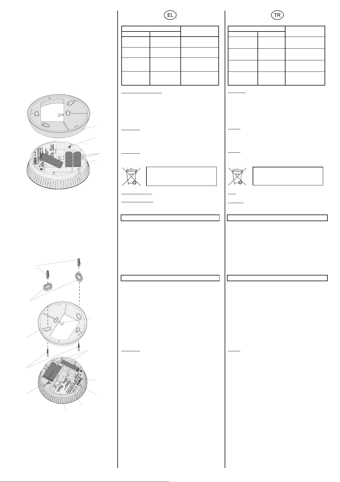
B
C
ΣÞματα μετÜ την ακýρωση του συναγερμο ý
ΣÞμα
οπτικü ακουστικü
αναβοσβÞνει
περ. κÜθε 1 s
Παλμüς περ.
κÜθε 48 s
αναβοσβÞνει
περ. κÜθε 1 s
Παλμüς περ.
κÜθε 48 s
ΑντικατÜσταση μπαταριþν Εικüνα B
ΕÜν ξεπεραστε ß Þ προσεγγιστεß το κατþτατο üριο τÜσης της
μπαταρßας, ακολουθεß οπτικÞ και ακουστικÞ ειδοποßηση (βλÝπε
πßνακα σημÜτων λειτουργßας και συναγερμοý) .
1. Ανοßξτε τη συσκευÞ που αποτελεßται απü δýο τμÞματα (βÜση B1
και ανιχνευτÞς καπνοý B2) περιστρÝφοντας προς την αντßθετα
φορÜ απü τους δεßκτες του ρολογιοý (ασφÜλεια μπαγιονÝτας).
2. ΑφαιρÝστε τις μπαταρßες (B3) απü τις θÞκες τους.
B1
B4
B3
B2
C1
C2
C11
C3
C10
C4
C9
C5
C6
C8
C7
3. Τοποθε τÞστε τρεις νÝες μπαταρßες με σωστÞ θÝση των πüλων.
ΠΡΟΣΟΧΗ:
ΕπιτρÝπεται να χρησιμοποιηθοýν μüνον μπαταρßες του τýπου 1,5V
LR6, Alkaline Mignon, AA.
4. Τοποθε τÞστε τον ανιχνευτÞ καπνοý στη βÜση και ασφαλßστε τον
περιστρÝφοντας τον προς τη φορÜ των δεικτþν του ρολογιοý. Τα
κüκκινα τρßγωνα βοηθοýν τον προσανατολισμü (B4/E4).
ΠΡΟΣΟΧΗ:
Ο ανιχνευτÞς καπνοý μπορεß μüνον με τοποθετημÝνες τις μπαταρßες
να στερεωθεß στη βÜση.
5. Πραγματοπ οιÞστε Ýναν Ýλεγχο λειτουργßας (βλÝπε σελßδα 4) .
ΣυντÞρηση και φροντßδα
α φορÜ το μÞνα:
να πραγματοποιÞσετε Ýναν Ýλεγχο λειτουργßας (βλÝπε σελßδα 4).
Μßα φορÜ το μÞνα:
καθαρßστε περιστασιακÜ τον ανιχνευτÞ καπνοý απü την
εξωτερικÞ του πλευρÜ, π.χ. με Ýνα υγρü πανß.
ΣυνιστÜτε η πλÞρης αντικατÜσταση της συσκευÞς ανÜ 10 χρüνια.
ΚατασκευÞ του ανιχνευτÞ καπνοý
Εικüνα C
C1 Βýσμα
C2 Δακτυλßδια απüστασης
C3 ΒÜση
C4 Βßδες
C5 ΑνιχνευτÞς καπνοý
C6 ΚουμπωτÞ κλÝμα για την καλωδßωση
C7 Αποθηκευτικüς χþρος για καλþδια
C8 ΚÜλυμμα δομοστοιχεßου
C9 ΘÝση τοποθÝτησης στοιχεßου ρελÝ Þ στοιχεßου ασýρματης
μετÜδοσης
C10 ΘÞκες μπαταρßας με μπαταρßες
C11 ΣτÞριγμα συνδετÞρων καλωδßων
ΤεχνικÜ στοιχεßα
Τροφοδοσßα τÜσης
• απü μπαταρßες 3x1,5V LR6, Alkaline Mignon, AA
• ΔιÜρκεια ζωÞς μπαταριþν: τυπικÜ 5 χρüνια (χωρßς ενεργοποßηση
συναγερμοý)
• ΜÞνυμα ΕξασθενημÝνη μπαταρßα: κÜθε 48s αναβοσβÞνουν τρßα
σýντομα οπτικÜ σÞματα και ακοýγεται Ýνα σýντομο ηχητικülσÞμα
Ευαισθησßα απüκρισης
EN 14604 2005
Σηματοδüτηση
• πομπüς ακουστικοý σÞματος: > 85dB(A) σε απüσταση 3m
• οπτικÞ Ýνδειξη: ΦωτεινÞ δßοδος κüκκινη
Σýνδεση σε δßκτυο
• Ýως και 40 ανιχνευτÝς καπνοý με Ýνα δßκλωνο, συστρεμμÝνο
καλþδιο, π.χ. του τýπου J-Y(St)Y 2x2x0,6mm
• Συνολικü μÞκος καλωδßου: Ýως 400m
ΠΡΟΣΟΧΗ:
ΕπιτρÝπεται να συνδεθο ýν μεταξý τους σε δßκτυο μüνον οι ανιχνευτÝς
καπνοý DELTA reflex με μπαταρßα (5TC1 290, 5TC1 293, 5TC1 294).
• Δυνατüτητα πρüσθετης επÝκτασης με κουμπωτÜ στοιχεßα:
Στοιχεßο ρελÝ ανßχνευσης καπνοý
- ΤÜση ζεýξης: Ýως 30V DC / 42V AC
- Ρεýμα ζεýξης: Ýως 1A DC / 0,5A AC
Στοιχεßο ανßχνευσης καπνοý wave uni
- Συχνüτητα εκπομπÞς: 868MHz
- ΕμβÝλεια σε ελεýθερο πεδßο: περ. 100m
ΜηχανικÜ στοιχεßα
• Περßβλημα: Πλαστικü (ABS,ASA)
• ΔιαστÜσεις περιβλ Þματος (∅ x Υ): 120 x 44mm
• ΒÜρος (χωρßς μπαταρßες): 148g
• ΤοποθÝτηση: επÜνω στο επßχρισμα με Þ χωρßς τα δακτυλßδια
απüστασης
ΗλεκτρικÞ ασφÜλεια
Βαθμüς προστασßας (κατÜ EN 60529): IP30
ΠροδιαγραφÝς EMV
EN 50130-4, EN 61000-6-3
ΣυνθÞκες περιβÜλλοντος
• Θερμοκρασßα περιβÜλλοντος κατÜ τη λειτουργßα: 0 Ýως + 50°C
• Θερμοκρασßα αποθÞκευσης: -25 Ýως +70°C
• ΣχετικÞ υγρασßα του αÝρα (χωρßς υγροποßηση υδρατμþν):
5% Ýως 93%
ηχητικü σÞμα
ΕΚΤΟΣ
ηχητικü σÞμα
ΕΚΤΟΣ
3 σýντομα
ηχητικÜ σÞματα
περ. κÜθε 4 s
ηχητικü σÞμα
ΕΚΤΟΣ
Οι Üδειες μπαταρßες θα πρÝπει να
απορρßπτονται σýμφωνα με τους
ισχýοντες κανονισμοýς
ακουστικü
τοπικÞ ακýρωση
συναγερμοý με ýπαρξη
καπνοý στο χþρο
τοπικÞ ακýρωση
συναγερμοý χωρßς ýπαρξη
καπνοý στο χþρο
λαμβανüμενη ακýρωση
συναγερμοý με ýπαρξη
καπνοý στο χþρο (σε
σýνδεση δικτýου)
λαμβανüμενη ακýρωση
συναγερμοý χωρßς ýπαρξη
καπνοý στο χþρο (σε
σýνδεση δικτýου)
Alarm işaret vermesinden sonra sinyaller
yakl. 1 s.’lik
aral
yakl. 48 s.’lik
aral
yakl. 1 s.’lik
aral
yakl. 48 s.’lik
aral
Pil değiştirme Resim B
Pil voltajı asgari sınıra geldiğinde veya bu sınırın altına düştüğünde
görsel ve sesli bir alarm verilir (bkz. Çalışma ve Alarm sinyalleri
tablosu).
1. İki parçadan oluşan cihaz (Altlık B1 ve Duman detektörü B2),
saat istikametinin tersine döndürülerek açılır (bayonet duyu).
Sinyal
görsel sesli
ıklarla yanıp-
söner
ıklarla yanıp-
söner
ıklarla yanıp-
söner
ıklarla yanıp-
söner
sinyal sesi
KAPALI
sinyal sesi
KAPALI
4 saniyelik
aral
ısa sinyal sesi
k
sinyal sesi
KAPALI
ıklarla 3
Durum
odada duman varken
lokal alarm s
odada duman yokken
lokal alarm s
odada duman varken
ınan alarm sıfırlaması
al
ı ağı varsa )
(cihaz
odada duman yokken
ınan alarm sıfırlaması
al
ı ağı varsa )
(cihaz
ıfırlaması
ıfırlaması
2. Pilleri (B3) pil yuvasından dışarı çıkarınız.
3. Üç adet yeni pili kutupları doğru olacak şekilde yerleştiriniz.
DİKKAT:
Sadece 1,5V LR6, Alkalin Mignon, AA tipi pil kullanılmalıdır.
4. Duman detektörünü altlığa geçiriniz ve saat istikametinde
çevirerek sabitleyiniz. Kırmızı üçgenler (B4/E4) istikameti gösterir.
DİKKAT:
Duman detektörü yalnızca içinde pil varsa eğer altlığa takılabilir.
5. Fonksiyon testi yapınız (bkz. sayfa 4).
Biten piller, geçerli atık yönetmeliklerine
uygun şekilde çöpe atılmalııdır
Bakım ve Onarımı
Aylık:
Bir fonksiyon testiyapınız (bkz sayfa 4).
6 ayda bir:
Duman detektörü temizleme, örn. az nemlendirilmiş bez ile.
Cihaz değişiminin 10 yıl sonra yapılması tavsiye edilir.
Duman detektörünün yapısı
Resim C
C1 Saplama/tespit pimi
C2 Pul
C3 Altlık
C4 Vidalar
C5 Duman detektörü
C6 Cihaz ağı oluşturma için klemens
C7 Kablo biriktirme boşluğu
C8 Modül kapağı
C9 Kablosuz veya röle modül için yuva
C10 Pil yuvası ve piller
C11 Kablo cırtı bağlama yeri
Teknik özellikler
Voltaj beslemesi
• 3x1,5V LR6, Alkalin Mignon, AA piller aracılığıyla sağlanır
• Pil ömrü: normalde 5 yıl (Alarm verme dışında)
• Pil zayıf bildirimi: her 48 saniyede üç defa kısa yanıp-söner ve
kısa sesli sinyal
Algılama hassasiyeti
EN 14604 2005
Sinyal verme
• sesli sinyal verici: > 85dB(A) 3m mesafede
• gösterge: kırmızı lamba
Cihaz ağı oluşturma
• Azami 40 duman detektörü, çift damarlı, burulmuş kablo ile, örn.
Tip. J-Y(St)Y 2x2x0,6mm
• Toplam kablo uzunluğu: azami 400m
DİKKAT:
Sadece DELTA reflex pilli duman detektörleri (5TC1 290, 5TC1 293,
5TC1 294) ile ortak bir cihaz ağı oluşturulabilir.
• Takılabilir ek modüller:
Duman detektörü röle modülü
- Şalt gerilimi: azami 30V DC / 42V AC
- Şalt akımı: azami 1A DC / 0,5A AC
Duman detektörü wave uni modülü
- Radyo frekansı: 868MHz
- Açık alanda algılama alanı: yakl. 100m
Mekanik özellikler
• Gövde: Plastik (ABS,ASA)
• Gövde ölçüleri (∅ x H): 120 x 44mm
Ağırlık (pilsiz): 148g
•
•
Montaj: Sıva üstüne, mesafe pulu ile veya pulsuz montaj
Elektriksel emniyet
Koruma tipi (EN 60529'e göre) : IP30
Elektro-manyetik uyumluluk koşulları
EN 50130-4, EN 61000-6-3
Ortam koşulları
• Çalışma sırasında ortam sıcaklığı: 0° ila + 50°C arası
• Depolama sıcaklığı: -25° ila +70°C arası
• Göreli nem (yoğunlaşmayan): %5 ila %93 arası
251653.41.03 "D S 09 " Σελßδα 2 απü 4 Sayfa 2 sayfanýn 4

Υ
ης
D
Έγκριση
Αναγνþριση VdS: βλÝπε πινακßδα τýπου
Χαρακτηρισμüς CE
EMC 2004/108/EG
89/106/EWG, CPD 0786-CDP-20419
ποδεßξεις εγκατÜστασ
ΥΠΟΔΕΙΞΗ:
• Ένας ανιχνευτÞς καπνοý εντοπßζει την ýπαρξη καπνοý, üχι üμως
τη φωτιÜ Þ τη παραγüμενη θερμüτητα.
• Ένας ανιχνευτÞς καπνοý εποπτεýει μüνον μßα συγκ εκριμÝνη
περιοχÞ. Για να καλυφθεß ολüκληρος ο χþρος κατοι κßας
(διαμÝρισμα), θα πρÝπει να τοποθετηθοýν και ενδεχομÝνως να
συνδεθοýν σε δßκτυο περισσüτεροι ανιχνευτÝς καπνοý.
• Τα κουμπωτÜ πρüσθετα στοιχεßα προσφÝρουν πρüσθετη
ασφÜλεια, π.χ. για τον Ýλεγχο μßας κüρνας, ενüς σηματοδüτη Þ
μßας συσκευÞς τηλεφþνου.
• Πριν την τοποθ Ýτηση των μπαταριþν και τη διεξαγωγÞ του ελÝγχου
λειτουργßας, ο ανιχνευτÞς καπνοý θα πρÝπει να Ýχει περßπου την ßδια
θερμοκρασßα üπως και το σημεßο τοποθÝτησης, προκειμÝνου να
αποτραπεß η συμπýκνωση εντüς του θαλÜμου μÝτρησης, που θα
μποροýσε να οδηγÞσει σε εσφαλμÝνη λειτουργßα.
U
• Η συσκευÞ επιτρÝπεται να χρησιμοποιηθεß αποκλειστικÜ και μüνον
• Ο ανιχνευτÞς καπνοý επιτρÝπεται να συνδεθεß σε δßκτυο μüνον με
• Μη βÜφετε και μην κολλÜτε αντικεßμενα επÜνω στον ανιχνευτÞ
• Ο ανιχνευτÞς καπνοý λειτουργε ß σωστÜ μüνον με τις
• Στον Ýλεγχο λε ιτουργßας θα πρÝπει να τηρηθεß μßα απüσταση
ΤοποθÝτηση και καλωδßωση
Σημεßο τοποθÝτησης
ΕλÜχιστη προστασßα Εικüνα D
• ΑνιχνευτÝς καπνοý θα πρÝπει να τοποθετοýνται σε κÜθε üροφο,
ΙδανικÞ προστασßα Εικüνα D +
• Σε κÜθε χþρο κατοικßας και σε κÜθε κρεβατοκÜμαρα θα πρÝπει
• Για να εξασφαλιστεß, üτι σε περßπτωση πυρκαγιÜς θα
ΥΠΟΔΕΙΞΗ:
• ΚÜθε ανιχνευτÞς κßνησης μπορεß να εποπτεýσει μßα επιφ Üνεια
• Τοποθε τεßτε τους ανιχνευτÝς καπνοý üσο πιο κοντÜ στο κÝντρο
• Στους χþρους με κεκλιμÝνη οροφÞ ο ανιχνευτÞς κßνησης θα
• Σε χþρους με ýψος μεγαλýτερο απü 3m απαιτοýνται
• ΚατÜ την τοπο θÝτηση θα πρÝπει να ληφθοýν υπ' üψιν τα τυπικÜ
ΑκατÜλληλα σημεßα τοποθÝτησης
Για λüγους ασφαλεßας, αλλÜ και για να αποφευχθοýν λανθασμÝνοι
συναγερμοß και εσφαλμÝνες λειτουργßες, οι ανιχνευτÝς κßνησης δεν
θα πρÝπει να τοποθετοýνται στους παρακÜτω χþρους:
• Σε χþρους üπου υπÜρχουν δυνατοß υδρατμοß, σκüνες Þ καπνοß.
• Σε χþρους με εστßες φωτιÜς και ανοικτÜ τζÜκια.
• ΚοντÜ σε ηλεκτρικÜ πεδßα (π. χ. σε λαμπτÞρε ς φθορισμοý , σε
• Σε χþρους üπου επικρατοýν θερμοκρασßες μικρüτερες απü 0°C Þ
ΤοποθÝτηση Εικüνα E
1. Ανοßξτε τη συσκευÞ που αποτελεßται απü δýο τμÞματα (βÜση E3
2. ΚολλÞστε το αυτοκüλλητο που συνοδε ýει τη συσκευÞ (E9)
ΥΠΟΔΕΙΞΗ:
ΤοποθετÞστε τον ανιχνευτÞ καπνοý Ýτσι, þστε κατÜ την εßσοδο στο
χþρο να εßναι ορατÞ η φωτεινÞ δßοδος. Γι α τον προσανατολισμü
μπορεßτε να χρησιμοποιÞσετε την επιγραφÞ SIEMENS επÜνω στο ν
(E7) ανιχνευτÞ κßνησης (E6) και στη βÜση (E3) O.
3. Στερεþστε τη βÜση (E3) με το υλικü τοποθÝτησης που συνοδεýει τη
4. Το ποθετÞστε τις μπαταρßες που συνοδεýουν τη συσκευÞ μÝσα
ΠΡΟΣΟΧΗ:
Ο ανιχνευτÞς καπνοý μπορεß να στερεωθεß στη βÜση μ üνον εÜν Ýχουν
τοποθετηθεß οι μπαταρßες.
λειτουργßες (π.χ. απü διακυμÜνσεις της πßεσης Þ απü ρεýμα
αÝρα) θα πρÝπει να εßναι τοποθετημÝνο το κÜλυμμα του
δομοστοιχεßου
5. Το ποθετÞστε τον ανιχνευτÞ καπνοý στη βÜση και ασφαλßστε τον
6. Πραγματοπ οιÞστε Ýναν Ýλεγχο λειτουργßας (βλÝπε παρακÜτω).
ΚΙΝΔΥΝΟΣ
για μüνιμη εγκατÜσταση σε στεγνοýς εσωτερικοýς χþρους.
Üλλους ανιχνευτÝς του ßδιου κα τασκευαστικοý τýπου.
καπνοý.
προβλεπüμενες αλκαλικÝς μπαταρßες. Μη χρησιμοποιεßτε
επαναφορτιζüμενες μπαταρßες Þ τροφοδοτικÜ.
ασφαλεßας τουλÜχιστον 50cm, προκειμÝνου να αποφευχθοýν οι
βλÜβες της ακοÞς απü τον Þχο του συναγε ρμοý.
κατÜ προτßμηση στο διÜδρομο, αλλÜ και σε κÜθε κρεβατοκÜμαραe.
να τοποθετηθοýν ανιχνευτÝς καπνοý.
πραγματοποιηθεß εγκαßρως και σε üλους τους χþρους η
ειδοποßηση για ενδεχüμενη πυρκαγιÜ, προτεßνεται να συνδεθοýν
üλοι οι ανιχνευτÝς καπνοý σε δßκτυο.
60m²το πολý.
της οροφÞς. ΕÜν κÜτι τÝτοιο δεν εßναι εφικτü, δια τηρÞστε μßα
ελÜχιστη απüσταση 15cm απü τον τοßχο Þ απü γωνßες.
πρÝπει να τοποθετηθε ß σε απüσταση 90cm περßπου απü το
ψηλüτερο σημεßο της οροφÞς.
περισσüτερες συσκευÝς (ýψος τοποθÝτησης στον τοßχο: 2,5m).
ρεýματα αÝρα, ανÜλογα με τις ιδιαßτερες συνθÞκες που
επικρατοýν στο χþρο.
λαμπτÞρες χαμηλÞς κατανÜλωσης Þ ηλεκτρικÜ καλþδια,
ελÜχιστη απüσταση: 50cm).
μεγαλýτερες απü +50°C.
και ανιχνευτÞς καπνοý E6) περιστρÝφοντας προς την αντßθετα
φορÜ απü τους δεßκτες του ρολογιοý (ασφÜλεια μπαγιονÝτας).
βÜφεται" στην εξωτερικÞ πλευρÜ της βÜσης.
συσκευÞ (βßδες E5 και βýσματα E1) στην οροφÞ. ΕÜν απαιτεßται
μεγαλýτερος χþρος χρησιμοποιÞστε τα δακτυλßδια απüστασης
(E2). Για τη στερÝωση καλωδßων Þ σωληνþσεων θα πρÝπει να
χρησιμοποιηθεß το στÞριγμα για συνδετÞρες καλωδßων (E8).
στις θÞκες (C10) σýμφωνα με την περιγραφÞ των πüλων.
.t sein.
περιστρÝφοντας τον προς τη φορÜ των δεικτþν του ρολογιοý. Τα
κüκκινα τρßγωνα βοηθοýν τον προσανατολισμü (B4/E4).
Για να αποφευχθοýν εσφαλμÝνες
"Να μη
Onay
VdS-Onayı: bkz. Model levhası
CE- İşareti
EMC 2004/108/EG
89/106/EWG, CPD 0786-CDP-20419
Kurulum bilgileri
BİLGİ:
• Bir duman detektörü dumanı algılar, ancak yangını ya da
meydana gelen ısıyı algılamaz.
• Bir duman detektörü sadece belirli bir bölgeyi denetler. Tüm evi
kapsaması için, yeterli miktarda detektör monte edilmesi ve
gerektiğinde bir cihaz ağı oluşturulması gerekir.
• Takılabilir ek modüllerle ek emniyet sağlanır. Örn. bir sirenin, bir
sinyal lambasının ya da bir telefon arama cihazının devreye
sokulmasıyla.
•
Pilleri takmadan ve fonksiyon testi yapmadan önce duman
detektörünün montaj yerinin ortam ısısına gelmesi
beklenmelidir, böylece ölçüm yuvasında nem oluşması ve hatalı
fonksiyon olması önlenmiş olur.
U
• Cihaz sadece kuru kapalı mekanlarda sabit montaj amacıyla
• Sadece aynı model duman detektörleriyle bir cihaz ağı
• Duman detektörünün üstüne bir şey yapıştırılmamalı ve
• Duman detektörü sadece burada yazılı alkalin pillerle doğru
• Fonksiyon testi sırasında, alarm sesinin kulaklara zarar
Montaj ve kablaj
Montaj yeri
Asgari koruma için Resim D
• Her katta, tercihen koridorda ve ayrıca her yatak odasına birer
Uygun koruma için Resim D +
• Her oturma odasına ve yatak odasına ayrıca ek olarak her
• Meydana gelen bir yangını mümkün olduğunca erken ve her
BİLGİ:
• Her duman detektörü azami 60m²lik bir alanı denetleyebilir.
•
•
•
•
Uygun olmayan montaj yerleri
Güvenlik nedeniyle ve yanlış alarm verilmesini önlemek için duman
detektörleri aşağıdaki yerlere monte edilmemelidir:
• Yoğun su buharı, toz ya da dumanın oluştuğu odalar.
•
• Elektriksel alanların yakın çevresi (örn. flüoresan enerji tasarruf
•
Montaj, Resim E (bkz. sonraki sayfa)
1. İki parçadan oluşan cihaz (altlık E3 ve duman detektörü E6)
2. Ürünle birlikte verilİki parçadan oluşan cihaz (altlık E3 ve duman
BİLGİ:
Duman detektörünü, odaya girildiğinde lamba iyi görülecek şekilde
monte ediniz. Duman detektörü (E6) ve altlık (E3) üzerindeki
“SIEMENS” yazıları (E7) burada yön bulucu olarak kullanılabilir.
3. Altlığı (E3) ambalaj içinde gelen montaj malzemesi (vidalar E5
4. Cihazla birlikte verilen üç pili, kutuplarına dikkat ederek pil
DİKKAT:
Pilleri yerleştirilmemiş duman detektörünün altlığa takılması
mümkün değildir. Basınç değişimleri veya hava akımı nedeniyle
fonksiyon hatalarının meydana gelmesini önlemek için modül
kapağı takılmış olmalıdır.
5. Duman detektörü altlık üzerine yerleştirilir ve saat istikametinde
kullanılabilir.
oluşturabilir.
boyanmamalı.
çalışır. Akü ya da şebeke adaptörü kullanmayınız.
vermesini önlemek için en az 50 cm'lik bir emniyet mesafesi
bırakılmalıdır.
duman detektörü monte edilmelidir.
koridora birer duman detektörü monte edilmelidir.
odaya duyurabilmesini sağlamak için tüm duman detektörlerinin
ortak bir ağa bağlanması gereklidir.
Duman detektörünü mümkün olduğunca tavanın ortasına
monte ediniz. Eğer bu olanaklı değilse tavana, duvar ve
köşeden en az 15 cm'lik mesafede monte ediniz.
Eğimli, çıkıntılı ya da kemerli tavanlarda, duman detektörünü
tavandan yakl. 90cm yükseğe monte ediniz.
3 m'den daha yüksek odalarda birden fazla cihaz gereklidir.
(duvarda montaj yüksekliği: 2,5m).
Montaj yerlerini seçerken, tipik ve ortamda mevcut koşullara
göre farklı olabilen hava akımları göz önünde bulundurulmalıdır.
Ateş kaynağı ve şömine bulunan odalar.
lambaları ve bunların kabloları; asgari mesafe: 50cm).
Ortam sıcaklıkları 0°C'den düşük veya +50°C'nin üzerinde olan
yerler.
saat istikametinde döndürülerek açılır (bayonet duy).
detektörü E6) saat istikametinde döndürülerek açılır (bayonet duy).
ve E1 dübel) ile tavana monte ediniz. Gerekiyorsa mesafe
pullarını (E2) kullanınız. Kabloları ya da kablo hortumlarını
sabitlemek için, cırt bağlama yerini (E8) kullanınız.
yuvasına (C10) yerleştiriniz.
döndürülerek kapatılır. Kırmızı üçgenler (B4/E4) istikameti gösterir.
TEHLİKE
6. Fonksiyon testi yapınız. (bkz. aşağı)
251653.41.03 "D S 09 " Σελßδα 3 απü 4 Sayfa 3 sayfanýn 4

A
E
F
Έλεγχος λειτουργßας:
Αφοý ολοκληρωθεß η τοποθÝτηση, αλλÜ και μια φορÜ κÜθε μÞνα, θα
πρÝπει να ελεγχθεß η σωστÞ λει τουργßα κÜθε ανιχνευτ Þ καπνοý. Για
το σκοπü αυτü θα πρÝπει να κρατηθεß πατημÝνο το πλÞκτρο
συναγερμοý/ακýρωσης (A2) για 2 δε υτερüλεπτα περßπου και μÝχρι
το σημεßο πßεσης.
• ΕÜν ακουστεß το ηχητικü σÞμα μ ßα φορÜ και αναβοσβÞσει η
E1
E2
Do not paint
E9
E8
E3
E4
E7
E5
E6
+
F1
-
+
F2
-
F4
F3
F6
-
+
F5
φωτεινÞ δßοδος 10 φορÝς, τüτε ο ανιχνευτÞς καπνοý λειτουργεß
σωστÜ.
• ΕÜν ο Ýλεγχ ος λειτουργßας Ýχει αρνητικÜ αποτελÝσματα, τüτε η
φωτεινÞ δßοδος θα αρχßσει να αναβοσβÞνει συνεχþς. Ο
ανιχνευτÞς καπνοý θα πρÝπει σε αυτÞ την περßπτωση να
αντικατασταθεß.
• ΕÜν δεν ακουστεß το ηχητικü σÞμα και δεν αναβοσβÞνει η φωτεινÞ
δßοδος, θα πρÝπει να ελÝγξετε την πολικüτητα των μπαταριþν.
ΕÜν και αυτÞ η ενÝργεια δεν Ýχει αποτÝλεσμα, τüτε θα πρÝπει να
αντικατασταθεß ο ανιχνευτÞς καπνοý.
Σýνδεση ανιχνευτþν καπνοý σε δßκτυο
Μποροýν να συνδεθοýν μεταξý τους Ýως και 40 ανιχνευ τÝς καπνοý.
ΕÜν εντοπιστεß καπνüς μüνον απü Ýναν ανιχνευτÞ, τüτε θα
ενεργοποιηθεß ο συ ναγερμüς üλων των συνδεμÝνων συσκευ þν
(Εικüνα F). Η φωτεινÞ δßοδος αναβοσβÞνει μüνον στον ανιχνευτÞ που
Ýχει ενεργοποιÞσει το συνα γερμü. Με αυτü τον τρüπο θα μπορÝσετε
να εντοπßσετε εýκολα τον ανιχνευτÞ κßνησης που ενεργοποßησε το
συναγερμü. Η σýνεση των ανι χνευτþν πραγματοποιεßται με Ýνα
δßκλωνο συστρεμ μÝνο καλþδιο (π.χ. J-Y(ST)Y 2x2x0,6mm). Το
συνολικü μÞκος του καλωδßου των συνδεδεμÝνων ανι χνευτþν καπνοý
δεν πρÝπει να ξεπερνÜ τα 400m. Σε περßπτωσ η λανθασμÝνης
πολικüτητας, η προστασßα αποτρÝπει τη φθορÜ του ανιχνευτÞ. Θα
ακουστεß μßα ηχητικÞ ειδοποßηση.
ΠΡΟΣΟΧΗ:
• Θα πρÝπει να δοθεß προσοχÞ, þστε να μην πιαστεß κÜποιο
καλþδιο ανÜμεσα απü τη φλÜντζα του επÜνω και κÜτω τμ Þματος
της συσκευÞς.
• Η σýνδεση σε δßκτυο επιτρÝπεται να γßνει μüνον με συσκευÝς του
ßδιου τýπου κατασκευÞς, σε δι αφορετικÞ περßπτωση ενδÝχεται να
παρουσιαστοýν εσφαλμÝνες λειτουργßες.
• Αφοý ολοκληρωθεß η εγκατÜσταση προτεßνεται Ýνας Ýλεγχος
δικτýωσης. Μπορεßτε να ενεργοποιÞσετε Ýναν συναγερμü καπνοý
(π.χ. με τσιγÜρο, αεροζüλ Þ ειδικÜ σπßρτα). Η επαναφορÜ του
συναγερμοý πραγματοποιεßται εßτε αυ τüματα, üταν ο καπνüς
απομακρυνθεß τελεßως απü το θÜλαμο μÝτρησης Þ εÜν πατηθ εß
τελεßως το πλÞκτρο ακýρωσης/συναγερμ οý.
• Η καλωδßωση της διασýνδεσης δεν πρÝπει να εßναι παρÜλληλη
προς τις γραμμÝς ηλεκτρικÞς ισχýος και τις δορυφ ορικÝς Þ Üλλες
γραμμÝς.
Σýνδεση σε δßκτυο Εικüνα F
F1 ΑνιχνευτÞς καπνοý με μπαταρßα
F2 ΚλÝμα δικτýωσης
F3 + Σýνδεση
F4 - Σýνδεση
F5 πρüσθετοι ανιχνευτÝς καπνοý με μπαταρßα
F6
ΚÜλυμμα δομοστοιχεßου
ΕνÝργειες για τη σýνδεση των ανιχνευτþν καπνοý σε δßκτυο:
1. ΑποσυνδÝστε την κλÝμα δικτýωσης (F2) απü τον ανιχνευτÞ καπνοý.
2. ΑφαιρÝστε τη μüνωση απü τα σýρματα σýνδεσης (περ. 6mm)
3. ΠερÜστε τα σýρματα στις επαφÝς ελατηρßου της κλÝμας (F2) .
4. Περ Üστε πÜλι την κλÝμα δικτýωσης στον ανιχνευτÞ κα-πνοý.
5. ΠραγματοποιÞστε Ýναν Ýλεγχ ο λειτουργßας (μüνον τοπικÜ).
Στοιχεßο ρελÝ και ασýρματης μετÜδοσης
ΠροσφÝρεται η δυνατüτητα εξοπλισμοý των ανιχνευτþν καπνοý με
Ýνα στοιχεßο ρελÝ Þ Ýνα στοιχεßο ασýρματης μετÜδοσης.
Στοιχεßο ρελÝ:
ΡελÝ με επαφÞ Üνευ δυναμι κοý για τον Ýλεγχο εξωτερικþν συσκευþν
σÞματος Þ συναγερμοý üπως π.χ. κüρνες, σειρÞνες Þ τηλεφωνικÝς
συσκευÝς.
Στοιχεßο ασýρματης μετÜδοσης:
Ασýρματη μεταβßβαση του συναγερμοý
ΥΠΟΔΕΙΞΗ:
Η ακριβÞς λειτουργ ßα με τη χρÞση του ρελÝ Þ του στοιχεßου
ασýρματης μετÜδοσης περιγρÜφεται στι ς αντßστοιχες οδηγßες
χρÞσης και τοποθÝτησης.
ΠιθανÝς αιτßες πυρκαγιÜς
Για να αποφευχθοýν οι πυρκ αγιÝς θα πρÝπει να αποκλειστοýν οι
παρακÜτω αιτßες:
• φθαρμÝνοι ηλεκτρικοß αγωγοß, λανθασμÝνη χρÞση και
υπερθÝρμανση ηλεκτρικþν συσκευþν
• τοποθÝτηση εýφλεκτων υλικþν δßπλα απü θερμÝς
ηλεκτρικÝς συσκευÝς üπως ηλεκτρικÜ σßδερα, τοστιÝρες και
φριτÝζες
• ανοικτÞ φλüγα üπως κεριÜ, τζÜκια χωρßς εποπτεßα
• κÜπνισμα στον καναπÝ Þ στο κρεβÜτι
• βραχυκυκλþματα στην κατÜσταση αναμονÞς (Stand-by)
ηλεκτρικþν συσκευþν üπως ραδιüφωνο, τηλεüραση,
ηλεκτρονικüς υπολογισ τÞς
• υπερφüρτωση και υπερθÝρμανση πρ ιζþν απü τη χρÞση
πολýπριζων
• λερωμÝνα καλ ýμματα απορροφητÞρω ν με συσσþρευση
λιπαρþνnουσιþν
• παιδιÜ που παßζουν με τη φωτιÜ
ΓενικÝς υποδεßξεις
• Οι συσκευÝς που παρουσιÜζουν βλÜβη θα πρÝπει να
αποστÝλλονται στην αρμüδια υπηρεσßα της Siemens AG.
• ΕÜν Ýχετε απορßες σχετικÜ με το προúüν, παρακαλοýμε
απευθυνθεßτε στο τμÞμα ΤεχνικÞς iΥποστÞριξης:
• Το εγχειρßδιο πρÝπει να παραδοθεß στον πελÜτη.
+49 (0) 180 50 50-222
℡
+49 (0) 180 50 50-223
www.siemens.com/automation/service&support
-
+
Fonksiyon testi:
Montaj yapıldıktan sonra ve her ay düzenli olarak mevcut her
duman detektörünün fonksiyonu test edilmelidir. Testi yapmak için
alarm/sıfırlama düğmesine (A2) basılmalıdır.
• Siren bir kez çalar ve lamba on kez yanıp-sönerse duman
detektörü doğru çalışıyor demektir.
• Fonksiyon testi başarısız olduğunda, sadece lamba sürekli
olarak yanıp-sönmeye başlar. Bu durumda duman detektörü
değiştirilmelidir.
• Ne siren sesi duyuluyor ne de lamba yanıp-sönüyorsa pillerin
doğru kutupla yerleştirilip yerleştirilmediği kontrol edilmelidir. Bu
da fayda etmediğinde duman detektörü değiştirilmelidir.
Duman detektörlerinin bir ağa bağlanması
40 adede kadar duman detektörü ortak ağa bağlanabilir. Sadece
bir duman detektörü duman algıladığında, aynı ağda bulunan tüm
cihazlar aynı anda alarm verir (Resim F). Lamba ise sadece alarmın
verilmesine neden olan detektörde yanıp-söner. Böylece alarmı
veren duman detektörü kolaylıkla bulunabilir. Detektörlerin birbirine
bağlanması burulmuş çift damarlı bir kablo (örn. JY(ST)Y
2x2x0,6mm) aracılığıyla yapılır. Ortak ağa bağlanan duman
detektörlerinin toplam kablom uzunluğu 400m'yi geçmemelidir.
Kutupların yanlış bağlanması halinde mevcut bir kutup emniyeti
detektörün hasar görmesini önler.
DİKKAT:
• Cihazın alt ve üst kısmı contaları arasına yabancı bir nesne veya
kablo olmamasına dikkat edilmelidir.
• Ortak ağ bağlantısı yapılırken yalnızca aynı model cihazlar
kullanılmalıdır, aksi takdirde hatalı fonksiyonlar meydana
gelebilir.
• Kurulum çalışmaları sona erdiğinde bir ağ testi yapılmalıdır.
Örneğin bir duman (sigara, aerosol vb.) alarmı verilebilir.
larmın sıfırlanması işlemi ya dumanın ölçüm yuvasından
tamamen çıkmasıyla otomatik olarak ya da alarm/sıfırlama
düğmesine sonuna kadar basılarak manüel olarak yapılır.
• Ağ şebekesinin kabloları, elektrik/uydu veya başka kablolara
yakın ve paralel döşenmemelidir.
Ağ bağlantısı Resim F
F1 Pilli duman detektörü
F2 Ağ klemensi
F3 + bağlantısı
F4 – bağlantısı
F5 Bağlanan diğer pilli duman detektörleri
F6 Modül kapağı
Duman detektörü ağının oluştuırulması hakkında ek bilgi:
1. Ağ klemensi (F2) duman detektöründen çıkarılır.
2. Bağlantı tellerinin izolasyonu soyulur (yakl. 6mm)
3. Teller ağ bağlantısı için yaylı klemense (F2) takılır.
4. Ağ klemensi tekrar duman detektörüne takılır.
5. Fonksiyon testi yapınız. (sadece lokal etkiye sahiptir).
Röle modülü ve kablosuz modül
Duman detektörünü takılabilir bir röle modülü ya da kablosuz
modül ile donatmak mümkündür.
Röle modülü:
Kornalar, sirenler ya da telefon arama cihazları gibi harici alarm ve
sinyal cihazlarını kontrol etmek için potansiyelsiz şalt kontaklı röle.
Kablosuz modül:
Radyo frekansı aracılığıyla alarm iletimi
BİLGİ:
Röle modülünün ya da kablosuz modülün tercih edilmesi halinde
nasıl çalıştıklarına dair bilgi bu parçalara ait kullanma ve montaj
talimatlarında bulunmaktadır.
Muhtemel yangın nedenleri
Yangınların meydana gelmesini önlemek için aşağıdaki yangın
nedenlerinin oluşmasına izin verilmemelidir:
• Hasarlı elektrik kabloları, elektrikli cihazların hatalı kullanılması
ve aşırı ısınmaları
• Ütü, tost makinesi ve fritöz gibi aşırı derecede ısınan elektrikli
cihazların yakınında kolay tutuşabilir maddelerin bulunması
• Mum, şömine ve çaydanlık altı ısıtıcısı gibi açıkta yanan ateş
• Divanda ya da yatakta sigara içmek
• Radyo, televizyon ve bilgisayarların uyku modunda bırakılması
nedeniyle kısa devre
• Çoklu prizlere birden fazla cihaz bağlanarak bunlara aşırı yük
binmesi ve ısınmaları
• Kirli ve yağ tabakası oluşmuş aspiratörler
• Ateşle oynayan çocuklar
Genel Bilgiler
• Hasarlı cihazlar, Siemens AG'nin yetkili birimine gönderilmelidir.
• Ürünle ilgili sorularınız için lütfen Teknik Destek birimimize
müracaat ediniz:
• Kullanma kılavuzu müşteriye teslim edilmelidir.
+49 (0) 180 50 50-222
℡
+49 (0) 180 50 50-223
www.siemens.com/automation/service&support
251653.41.03 "D S 09 " Σελßδα 4 απü 4 Sayfa 4 sayfanýn 4
 Loading...