


 Loading...
SINUMERIK
SINUMERIK 802D sl
Operating Instructions
Operating Instructions
Valid for Software version SINUMRIK 802D sl G/N 1.1 SINUMERIK 802D sl T/M 1.2
12/2006
6FC5397-0CP10-2BA0
Foreword
Description |
1 |
|
|
|
|
interfaces |
2 |
|
|
|
|
Application planning |
3 |
|
|
|
|
Assembling |
4 |
|
|
|
|
Connecting |
5 |
|
|
|
|
Operation (hardware) |
6 |
|
|
|
|
Commissioning (General) |
7 |
|
|
|
|
Initial start-up |
8 |
|
Commissioning the drives |
|
|
9 |
||
using HMI |
||
Edit a drive project with |
|
|
10 |
||
STARTER |
||
|
|
|
Starting Up the PLC |
11 |
|
Data Backup and Series |
|
|
12 |
||
Machine Start-Up |
||
|
|
|
Technical data |
13 |
|
|
|
|
Dimensional Drawings |
14 |
|
|
|
|
ESD guidelines |
A |
|
|
|
|
List of abbreviations |
B |
|
|
|

Safety Guidelines
This manual contains notices you have to observe in order to ensure your personal safety, as well as to prevent damage to property. The notices referring to your personal safety are highlighted in the manual by a safety alert symbol, notices referring only to property damage have no safety alert symbol. These notices shown below are graded according to the degree of danger.
Danger
indicates that death or severe personal injury will result if proper precautions are not taken.
Warning
indicates that death or severe personal injury may result if proper precautions are not taken.
Caution
with a safety alert symbol, indicates that minor personal injury can result if proper precautions are not taken.
Caution
without a safety alert symbol, indicates that property damage can result if proper precautions are not taken.
Notice
indicates that an unintended result or situation can occur if the corresponding information is not taken into account.
If more than one degree of danger is present, the warning notice representing the highest degree of danger will be used. A notice warning of injury to persons with a safety alert symbol may also include a warning relating to property damage.
Qualified Personnel
The device/system may only be set up and used in conjunction with this documentation. Commissioning and operation of a device/system may only be performed by qualified personnel. Within the context of the safety notes in this documentation qualified persons are defined as persons who are authorized to commission, ground and label devices, systems and circuits in accordance with established safety practices and standards.
Prescribed Usage
Note the following:
Warning
This device may only be used for the applications described in the catalog or the technical description and only in connection with devices or components from other manufacturers which have been approved or recommended by Siemens. Correct, reliable operation of the product requires proper transport, storage, positioning and assembly as well as careful operation and maintenance.
Trademarks
All names identified by ® are registered trademarks of the Siemens AG. The remaining trademarks in this publication may be trademarks whose use by third parties for their own purposes could violate the rights of the owner.
Disclaimer of Liability
We have reviewed the contents of this publication to ensure consistency with the hardware and software described. Since variance cannot be precluded entirely, we cannot guarantee full consistency. However, the information in this publication is reviewed regularly and any necessary corrections are included in subsequent editions.
Siemens AG |
Order No.: 6FC5397-0CP10-2BA0 |
Copyright © Siemens AG 2006. |
Automation and Drives |
02/2007 |
Technical data subject to change |
Postfach 48 48 |
|
|
90437 NÜRNBERG |
|
|
GERMANY |
|
|
Foreword
SINUMERIK documentation
The SINUMERIK documentation is organized in 3 parts:
•General Documentation
•User Documentation
•Manufacturer/service documentation
A list of documents, updated on a monthly basis, is available on the Internet for the available languages at:
http://www.siemens.com/motioncontrol
Select "Support"/"Technical Documentation"/"Overview of Documents".
The Internet version of the DOConCD (DOConWEB) is available at: http://www.automation.siemens.com/doconweb
You can find information on the training courses offered and FAQs (frequently asked questions) on the Internet under:
http://www.siemens.com/motioncontrol (under "Support")
Target group
This manual is intended for use by planners, configuration engineers, technicians, installation personnel, programmers, commissioning personnel, operators, service and maintenance personnel
Benefits
The operating instructions impart knowledge about the components and allow the addressed target groups to properly and safely install, set up, test and commission the SINUMERIK 802D sl.
Standard scope
This documentation only describes the functionality of the standard version. Additions or revisions made by the machine tool manufacturer are documented by the machine tool manufacturer.
Other functions not described in this documentation might be executable in the control. However, no claim can be made regarding the availability of these functions when the equipment is first supplied or in the event of servicing.
For the sake of simplicity, this documentation does not contain all detailed information about all types of the product and cannot cover every conceivable case of installation, operation, or maintenance.
Operating Instructions |
3 |
Operating Instructions, 12/2006, 6FC5397-0CP10-2BA0 |

Foreword
Technical support
In case of questions, please contact us through the following hotline:
Table 1 Europe and Africa time zone
A&D Technical Support
Phone: +49 (0) 180 / 5050 - 222
Fax: +49 (0) 180 / 5050 - 223
Internet: http://www.siemens.com/automation/support-request
E-mail: mailto:adsupport@siemens.com
Table 2 Asia and Australia time zone
A&D Technical Support
Phone: +86 1064 719 990
Fax: +86 1064 747 474
Internet: http://www.siemens.com/automation/support-request
E-mail: mailto:adsupport@siemens.com
Table 3 American time zone
A&D Technical Support
Phone: +1 423 262 2522
Fax: +1 423 262 2289
Internet: http://www.siemens.com/automation/support-request
E-mail: mailto:adsupport@siemens.com
Questions about the Manual
If you have any queries (suggestions, corrections) in relation to this documentation, please fax or e-mail us:
Fax: +49 (0) 9131 / 98 63315
E-mail: mailto:adsupport@siemens.com
Fax form: See the reply form at the end of this publication
SINUMERIK Internet address
http://www.siemens.com/sinumerik
4 |
Operating Instructions |
Operating Instructions, 12/2006, 6FC5397-0CP10-2BA0 |

Foreword
EC declaration of conformity
The EC Declaration of Conformity for the EMC Directive can be found/obtained
•on the Internet: http://www.ad.siemens.de/csinfo under product/Order No. 15257461
•at the relevant regional office of the A&D MC Group of Siemens AG.
Further notes
Note
This symbol always appears in the document where further information is provided.
Licensing provisions
The software SINUMERIK 802D sl is protected by national and international copyright laws and agreements. Unauthorized reproduction and distribution of this software or parts thereof is liable to prosecution. It will be prosecuted both according to criminal and civil law and may result in severe punishment or demands for compensation.
In the software SINUMERIK 802D sl, open source software is used. The licensing provisions for this software are located on the Toolbox CD and are to be observed accordingly.
Acceptance report
You can find a sample report for the acceptance of SINUMERIK 802D sl on the Internet at: http://support.automation.siemens.com under the heading Current > Acceptance reports
Operating Instructions |
5 |
Operating Instructions, 12/2006, 6FC5397-0CP10-2BA0 |

Foreword
6 |
Operating Instructions |
Operating Instructions, 12/2006, 6FC5397-0CP10-2BA0 |
Table of contents
|
Foreword |
................................................................................................................................................... |
3 |
1 |
Description............................................................................................................................................... |
13 |
|
|
1.1 |
System overview.......................................................................................................................... |
13 |
|
1.2 |
Description of components .......................................................................................................... |
17 |
2 |
interfaces................................................................................................................................................. |
21 |
|
|
2.1 |
CNC operator panel interfaces .................................................................................................... |
21 |
|
2.1.1 |
Compact flash card (CF card) slot............................................................................................... |
21 |
|
2.1.2 |
Ethernet interface......................................................................................................................... |
21 |
|
2.1.3 |
USB port (available soon)............................................................................................................ |
22 |
|
2.1.4 |
RS232 COM port ......................................................................................................................... |
22 |
|
2.1.5 |
PROFIBUS DP interface.............................................................................................................. |
23 |
|
2.1.6 |
DRIVE-CLiQ interface.................................................................................................................. |
24 |
|
2.1.7 |
Handwheel connection................................................................................................................. |
24 |
|
2.1.8 |
Digital inputs/outputs.................................................................................................................... |
25 |
|
2.2 |
MCPA module interfaces............................................................................................................. |
28 |
|
2.3 |
Interfaces of the machine control panel MCP 802D sl ................................................................ |
31 |
|
2.4 |
PP 72/48 I/O module interfaces................................................................................................... |
34 |
|
2.5 |
Interfaces of the machine control panel MCP.............................................................................. |
40 |
|
2.6 |
Interfaces of the DP/DP coupler.................................................................................................. |
42 |
3 |
Application planning................................................................................................................................. |
43 |
|
|
3.1 |
Overview...................................................................................................................................... |
43 |
|
3.2 |
General rules for operation of a SINUMERIK 802D sl................................................................. |
44 |
|
3.3 |
Rules regarding current consumption and power loss of a cubicle arrangement........................ |
45 |
4 |
Assembling.............................................................................................................................................. |
47 |
|
5 |
Connecting .............................................................................................................................................. |
49 |
|
|
5.1 |
Overall design of the SINUMERIK 802D sl.................................................................................. |
49 |
|
5.2 |
Connecting the protective conductor for the individual components........................................... |
50 |
|
5.3 |
Connection overview for SINUMERIK 802D sl............................................................................ |
51 |
|
5.4 |
Connecting the MCPA module..................................................................................................... |
52 |
|
5.5 |
Connecting an analog spindle...................................................................................................... |
53 |
|
5.6 |
Connecting the high-speed digital inputs/outputs at the MCPA module ..................................... |
55 |
|
5.7 |
Connecting the power supply....................................................................................................... |
55 |
|
5.8 |
Connecting the NC full keyboard to the CNC operator panel...................................................... |
57 |
|
5.9 |
Connecting the Ethernet interface............................................................................................... |
57 |
Operating Instructions |
7 |
||
Operating Instructions, 12/2006, 6FC5397-0CP10-2BA0 |
|||

Table of contents
|
5.10 |
Connecting the RS232 COM port............................................................................................... |
57 |
|
5.11 |
Connecting the PP72/48 I/O module .......................................................................................... |
58 |
|
5.12 |
Connecting the DP/DP coupler................................................................................................... |
61 |
|
5.13 |
Connecting the SINAMICS drive to the DRIVE-CLiQ interface.................................................. |
63 |
|
5.14 |
Connecting the digital inputs/outputs to the PCU....................................................................... |
64 |
|
5.15 |
Connecting the digital inputs/digital outputs to the PP72/48 I/O module.................................... |
64 |
|
5.16 |
Connecting the machine control panel to the PP72/48 I/O module............................................ |
65 |
|
5.17 |
Connecting shielded cables via the shield connection (PCU) .................................................... |
65 |
6 |
Operation (hardware)............................................................................................................................... |
67 |
|
|
6.1 |
Operator control and display elements....................................................................................... |
67 |
|
6.2 |
Status and error displays ............................................................................................................ |
67 |
7 |
Commissioning (General)........................................................................................................................ |
69 |
|
|
7.1 |
Initial commissioning (IBN).......................................................................................................... |
69 |
|
7.2 |
Access levels .............................................................................................................................. |
70 |
|
7.3 |
RCS tool...................................................................................................................................... |
71 |
|
7.4 |
STARTER commissioning tool.................................................................................................... |
72 |
|
7.4.1 |
The STARTER user interface..................................................................................................... |
72 |
|
7.4.2 |
Operating philosophy of the STARTER commissioning tool for SINAMICS S120..................... |
73 |
|
7.4.3 |
Diagnosis via STARTER............................................................................................................. |
74 |
|
7.4.3.1 |
Function generator...................................................................................................................... |
75 |
|
7.4.3.2 |
Trace function ............................................................................................................................. |
78 |
8 |
Initial start-up........................................................................................................................................... |
81 |
|
|
8.1 |
Turning on and booting the control system................................................................................. |
81 |
|
8.2 |
Language setting and file management...................................................................................... |
82 |
|
8.2.1 |
Creating and Editing Projects ..................................................................................................... |
82 |
|
8.2.2 |
Help, language and alarm files ................................................................................................... |
84 |
|
8.3 |
Setting the technology................................................................................................................. |
86 |
|
8.4 |
Input of the machine data............................................................................................................ |
88 |
|
8.5 |
Activating the high-speed digital inputs/digital outputs............................................................... |
89 |
|
8.6 |
Setting the Profibus addresses................................................................................................... |
90 |
|
8.7 |
Starting Up the PLC.................................................................................................................... |
93 |
|
8.8 |
Commissioning of drives (SINAMICS)........................................................................................ |
93 |
|
8.9 |
Set the axis/spindle-specific machine data................................................................................. |
93 |
|
8.9.1 |
Default settings of the axis machine data for feed axes............................................................. |
95 |
|
8.9.2 |
Default settings of the axis machine data for the spindle ........................................................... |
96 |
|
8.9.3 |
PLC-controlled axis................................................................................................................... |
101 |
|
8.9.4 |
Completion of the commissioning of the axes/spindle.............................................................. |
105 |
|
8.10 |
Completing the commissioning................................................................................................. |
105 |
8 |
Operating Instructions |
Operating Instructions, 12/2006, 6FC5397-0CP10-2BA0 |

Table of contents
9 |
Commissioning the drives using HMI..................................................................................................... |
107 |
|
|
9.1 |
Terminal assignment X20 / X21................................................................................................. |
113 |
10 |
Edit a drive project with STARTER........................................................................................................ |
117 |
|
|
10.1 |
Change a drive project OFFLINE............................................................................................... |
117 |
|
10.1.1 |
Example: Commissioning a direct measuring system for a spindle .......................................... |
122 |
|
10.1.2 |
Interface settings on PG/PC ...................................................................................................... |
134 |
|
10.2 |
Operating the STARTER control panel (motor rotating)............................................................ |
136 |
|
10.2.1 |
Loading the project into the drive unit........................................................................................ |
136 |
|
10.2.2 |
Operating the control panel........................................................................................................ |
139 |
11 |
Starting Up the PLC............................................................................................................................... |
147 |
|
|
11.1 |
Overview.................................................................................................................................... |
147 |
|
11.2 |
Programming Tool PLC802 ....................................................................................................... |
148 |
|
11.2.1 |
Selecting the target system........................................................................................................ |
148 |
|
11.2.2 |
Interface to PLC......................................................................................................................... |
149 |
|
11.3 |
First commissioning of the PLC................................................................................................. |
154 |
|
11.4 |
Commissioning modes of the PLC ............................................................................................ |
154 |
|
11.5 |
PLC alarms ................................................................................................................................ |
156 |
|
11.5.1 |
Overview.................................................................................................................................... |
156 |
|
11.5.2 |
General PLC alarms .................................................................................................................. |
157 |
|
11.5.3 |
User alarms................................................................................................................................ |
157 |
|
11.6 |
PLC Programming ..................................................................................................................... |
159 |
|
11.6.1 |
Overview.................................................................................................................................... |
159 |
|
11.6.2 |
Overview of commands ............................................................................................................. |
161 |
|
11.6.3 |
Explanation of the stack operations........................................................................................... |
163 |
|
11.6.4 |
Program organization................................................................................................................. |
171 |
|
11.6.5 |
Data management ..................................................................................................................... |
172 |
|
11.6.6 |
Testing and monitoring your program........................................................................................ |
172 |
|
11.7 |
PLC application Download/Upload/Copy/Compare................................................................... |
172 |
|
11.8 |
User interface............................................................................................................................. |
175 |
12 |
Data Backup and Series Machine Start-Up ........................................................................................... |
177 |
|
|
12.1 |
Data Backup............................................................................................................................... |
177 |
|
12.1.1 |
Internal data backup .................................................................................................................. |
177 |
|
12.1.2 |
External data backup................................................................................................................. |
178 |
|
12.1.3 |
Data backup via the RS232/Ethernet interface.......................................................................... |
179 |
|
12.1.4 |
External data backup via CF Card............................................................................................. |
180 |
|
12.1.5 |
Data backup in case of backlight failure.................................................................................... |
180 |
|
12.2 |
Series commissioning................................................................................................................ |
181 |
13 |
Technical data....................................................................................................................................... |
185 |
|
|
13.1 |
Electro-Magnetic Compatibility .................................................................................................. |
187 |
|
13.2 |
Transport and storage conditions.............................................................................................. |
188 |
|
13.3 |
Ambient operating conditions for the operation......................................................................... |
188 |
|
13.4 |
Specifications for Protection Class and Degree of Protection................................................... |
190 |
Operating Instructions |
9 |
Operating Instructions, 12/2006, 6FC5397-0CP10-2BA0 |

Table of contents
14 |
Dimensional Drawings........................................................................................................................... |
191 |
|
|
14.1 |
CNC operator panel (PCU) dimension drawing and hole drilling template ............................... |
191 |
|
14.2 |
Dimensions and hole drilling template of the machine control panel (MCP) ............................ |
195 |
|
14.3 |
NC full keyboard dimension and hole drilling templates ........................................................... |
197 |
|
14.4 |
PP72/48 peripheral module dimension drawing ....................................................................... |
199 |
|
14.5 |
Dimensional drawing MCPA module ........................................................................................ |
200 |
A |
ESD guidelines...................................................................................................................................... |
201 |
|
|
A.1 |
What does ESD mean? ............................................................................................................. |
201 |
|
A.2 |
Electrostatic Discharge to Persons ........................................................................................... |
201 |
|
A.3 |
Basic protective measures against discharge of static electricity ............................................. |
202 |
B |
List of abbreviations............................................................................................................................... |
203 |
|
|
B.1 |
Abbreviations 802D sl ............................................................................................................... |
203 |
|
Index |
...................................................................................................................................................... |
205 |
Tables |
|
|
|
Table 1 |
Europe and Africa time zone ......................................................................................................... |
4 |
|
Table 2 ......................................................................................................... |
Asia and Australia time zone |
4 |
|
Table 3 ...................................................................................................................... |
American time zone |
4 |
|
Table 1-1 ............................................................................................................................ |
PCU interfaces |
19 |
|
Table 2-1 ..................................................................................... |
Pin assignment of female connector X5 |
21 |
|
Table 2-2 ................................................................................................. |
Pin assignment of connector X8 |
22 |
|
Table 2-3 ..................................................................................... |
Pin assignment of female connector X6 |
23 |
|
Table 2-4 ......................................................................... |
Pin assignment of female connector X1 and X2 |
24 |
|
Table 2-5 ............................................................................................... |
Pin assignment of connector X30 |
25 |
|
Table 2-6 ......................................................................... |
Pin assignment of the connectors X20 and X21 |
27 |
|
Table 2-7 ...................................................................................................... |
Interfaces and status display |
29 |
|
Table 2-8 ................................................................................... |
Pin assignment of connectors X1 and X2 |
29 |
|
Table 2-9 ................................................................. |
Pin assignment of the connectors X1020 and X1021 |
30 |
|
Table 2-10 ............................................................................................. |
Pin assignment of connector X701 |
31 |
|
Table 2-11 ..................................................................................................................................... |
Interfaces |
32 |
|
Table 2-12 ................................................................. |
Pin assignment of the connectors X1201 and X1202 |
33 |
|
Table 2-13 ..................................................................................................................................... |
Interfaces |
35 |
|
Table 2-14 ......................................................................................... |
Female connector X2 pin assignment |
36 |
|
Table 2-15 ................................................................ |
Pin assignment of the connectors X111, X222, X333 |
36 |
|
Table 2-16 ..................................................................................................................................... |
Interfaces |
40 |
|
Table 2-17 ................................................................. |
Pin assignment of the connectors X1201 and X1202 |
41 |
|
10 |
Operating Instructions |
Operating Instructions, 12/2006, 6FC5397-0CP10-2BA0 |
|
Table of contents |
|
Table 5-1 |
Assignment of the X520 interface................................................................................................ |
54 |
Table 5-2 |
Electrical parameters of the load power supply for the CNC operator panel (X40) and for |
|
|
the PP72/48 I/O module (X1)....................................................................................................... |
55 |
Table 5-3 |
Pin assignment of the screw-terminal blocks X40 (on the PCU) and X1 (on the I/O |
|
|
module)........................................................................................................................................ |
56 |
Table 6-1 |
Status and error displays............................................................................................................. |
68 |
Table 6-2 |
Status displays............................................................................................................................. |
68 |
Table 7-1 |
Access level concept ................................................................................................................... |
70 |
Table 8-1 |
Example of machine data setting................................................................................................. |
90 |
Table 8-2 |
Setting the Profibus address........................................................................................................ |
90 |
Table 8-3 |
Setting the Profibus address on the PP 72/48............................................................................. |
91 |
Table 8-4 |
Assignment of the input/output bytes........................................................................................... |
91 |
Table 8-5 |
Setting the Profibus address on the DP/DP coupler.................................................................... |
92 |
Table 8-6 |
Assignment of the input/output bytes........................................................................................... |
92 |
Table 8-7 |
Setpoint/actual value assignment................................................................................................ |
93 |
Table 8-8 |
maximum configuration................................................................................................................ |
94 |
Table 8-9 |
Adapting the axis machine data for the milling machine ............................................................. |
94 |
Table 8-10 |
Adapting the axis machine data for the nibbling machine........................................................... |
95 |
Table 8-11 |
Adapting the axis machine data................................................................................................... |
95 |
Table 8-12 |
Default settings of the axis machine data for feed axes.............................................................. |
96 |
Table 8-13 |
Default settings of the axis machine data for the spindle............................................................ |
97 |
Table 8-14 |
Additional machine data............................................................................................................... |
98 |
Table 8-15 |
Machine data to be set................................................................................................................. |
98 |
Table 8-16 |
Machine data settings for analog spindle .................................................................................... |
99 |
Table 8-17 |
Machine data for the example.................................................................................................... |
100 |
Table 8-18 |
Additional machine data............................................................................................................. |
100 |
Table 8-19 |
Additional machine data............................................................................................................. |
101 |
Table 8-20 |
Adapting the axis machine data................................................................................................. |
101 |
Table 8-21 |
PLC axis control signals............................................................................................................. |
102 |
Table 8-22 |
Error messages via NCK ........................................................................................................... |
103 |
Table 9-1 |
Configuring the X20 clamp after SINAMICS commissioning using HMI.................................... |
113 |
Table 9-2 |
Configuring the X21 clamp after SINAMICS commissioning using HMI.................................... |
114 |
Table 10-1 |
Control word sequential control ................................................................................................. |
142 |
Table 11-1 |
Commissioning modes............................................................................................................... |
154 |
Table 11-2 |
PLC data types permitted in the control system........................................................................ |
160 |
Table 11-3 |
Operand identifier ...................................................................................................................... |
161 |
Table 11-4 |
Structure of V-range addresses (see user interface)................................................................. |
161 |
Operating Instructions |
11 |
Operating Instructions, 12/2006, 6FC5397-0CP10-2BA0 |

Table of contents
Table 11-5 |
802D sl address ranges............................................................................................................ |
161 |
Table 11-6 |
Special Marker SM Bit Definition .............................................................................................. |
162 |
Table 11-7 |
BASIC BOOLEAN INSTRUCTIONS......................................................................................... |
163 |
Table 11-8 |
OTHER BOOLEAN INSTRUCTIONS....................................................................................... |
163 |
Table 11-9 |
BYTE COMPARES................................................................................................................... |
163 |
Table 11-10 |
WORD COMPARES................................................................................................................. |
164 |
Table 11-11 |
DOUBLE WORD COMPARES................................................................................................. |
165 |
Table 11-12 |
REAL WORD COMPARES....................................................................................................... |
165 |
Table 11-13 |
TIMER....................................................................................................................................... |
166 |
Table 11-14 |
COUNTER................................................................................................................................. |
166 |
Table 11-15 |
MATH OPERATIONS ............................................................................................................... |
167 |
Table 11-16 |
INCREMENT, DECREMENT.................................................................................................... |
168 |
Table 11-17 |
LOGIC OPERATIONS .............................................................................................................. |
168 |
Table 11-18 |
SHIFT AND ROTATE OPERATIONS....................................................................................... |
169 |
Table 11-19 |
CONVERSION OPERATIONS................................................................................................. |
169 |
Table 11-20 |
PROGRAM CONTROL FUNCTIONS....................................................................................... |
170 |
Table 11-21 |
MOVE, FILL AND FIND OPERATIONS.................................................................................... |
171 |
Table 13-1 |
Connected loads....................................................................................................................... |
185 |
Table 13-2 |
Dimensions and weight............................................................................................................. |
185 |
Table 13-3 |
Digital inputs of the PP72/48 I/O module.................................................................................. |
186 |
Table 13-4 |
Digital outputs of the PP72/48 I/O module................................................................................ |
186 |
Table 13-5 |
Interference emission of electromagnetic fields as per EN 55011: Limit value class A, |
|
|
group 1...................................................................................................................................... |
187 |
Table 13-6 |
Interference emission via network alternating current supply in accordance with EN |
|
|
55011: Limit value class A, group 1.......................................................................................... |
187 |
Table 13-7 |
Shipping and storage conditions............................................................................................... |
188 |
Table 13-8 |
Climatic environmental conditions ............................................................................................ |
189 |
Table 13-9 |
Mechanical ambient conditions................................................................................................. |
189 |
12 |
Operating Instructions |
Operating Instructions, 12/2006, 6FC5397-0CP10-2BA0 |
Description |
1 |
1.1System overview
Overview
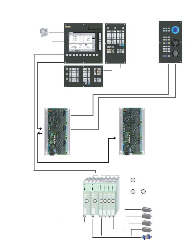
The CNC operator panel of the SINUMERIK 802D sl control systems combines all CNC, PLC, HMI and communication tasks in one component. The maintenance-free hardware integrates the DRIVE-CLiQ interface for the drives and PROFIBUS interface for the I/O modules with the slimline operator panel into a ready-to-install unit (Panel Control Unit).
The SINUMERIK 802D sl can control up to 6 axes digitally. At the most, up to 5 NC axes of these 6 axes and one PLC axis can be configured. Up to 2 of these 5 NC axes can be configured as a spindle.
Operating Instructions |
13 |
Operating Instructions, 12/2006, 6FC5397-0CP10-2BA0 |
Description
1.1 System overview
|
0DFKLQH FRQWURO SDQHO 0&3 |
&1& RSHUDWRU SDQHO 3&8 |
|
HOHFWURQLF KDQGZKHHO PD[
'LJLWDO LQSXWV |
|
|
|
|
|
|
|
|
GLJLWDO RXWSXWV |
|
|
|
|
|
|
|
|
'5,9( &/L4 |
|
|
|
|
|
|
|
|
352),%86 '3 |
|
|
|
|
|
|
|
|
|
|
|
|
|
1& IXOO NH\ERDUG |
|
|
|
|
|
|
|
|
XSULJKW RU |
|
|
|
|
|
|
|
|
DOWHUQDWLYHO\ EURDG IRUPDW |
|||
, 2 PRGXOH 33 |
|
|
|
|
, 2 PRGXOH 33 |
|
||
352),%86 '3 |
|
|
|
|
|
|
|
|
'5,9( &/L4 |
|
|
|
|
|
|
|
|
|
|
|
|
|
|
6PDUW /LQH RU $FWLYH /LQH 0RGXOHV |
||
|
|
|
|
|
|
PDLQV VXSSO\ |
||
|
|
|
|
|
|
|
|
6LQJOH PRWRU PRGXOH |
6,1$0,&6 6 |
|
|
|
|
|
|
|
|
|
|
|
|
|
|
|
|
3RZHU XQLW |
|
|
|
|
|
|
|
|
|
|
|
|
|
|
|
|
|
)HHG PRWRU |
0DLQV VXSSO\ |
|
|
|
|
|
|
|
)HHG PRWRU |
FRQGXFWRU |
|
|
|
|
|
|
|
|
|
|
|
|
|
|
|
|
)HHG PRWRU |
|
|
|
|
|
|
|
|
)HHG PRWRU |
ZKHQ XVLQJ D |
|
|
|
|
|
|
|
|
|
|
|
|
|
|
|
|
0DLQ VSLQGOH PRWRU |
PDFKLQH FRQWURO SDQHO |
|
|
|
|
|
|
|
|
Figure 1-1 SINUMERIK 802D sl with SINAMICS S120 (example configuration)
14 |
Operating Instructions |
Operating Instructions, 12/2006, 6FC5397-0CP10-2BA0 |

Description 1.1 System overview
&1& RSHUDWRU WDEOH ZLWK 0&3$ PRGXOH
HOHFWURQLF
KDQGZKHHO PD[
'LJLWDO LQSXWV |
|
|
|
|
|
|
|
|
'LJLWDO RXWSXWV |
|
|
|
|
|
|
|
|
'5,9( &/L4 |
|
|
|
|
|
|
|
|
352),%86 '3 |
|
|
|
|
|
|
|
|
|
|
|
|
|
|
|
0DFKLQH FRQWURO SDQHO 0&3 ' VO |
|
|
|
|
|
|
1& IXOO NH\ERDUG |
|
|
|
|
|
|
|
|
XSULJKW RU |
|
|
|
|
|
|
|
|
DOWHUQDWLYHO\ EURDG |
|
|
|
|
|
|
|
|
IRUPDW |
|
|
|
33 SHULSKHUDO PRGXOH |
|
|
33 SHULSKHUDO PRGXOH |
|
33 SHULSKHUDO PRGXOH |
|||
352),%86 '3 |
|
|
|
|
|
|
|
|
'5,9( &/L4 |
|
|
|
|
|
|
|
|
|
|
|
|
|
|
6PDUW /LQH RU $FWLYH /LQH 0RGXOHV |
||
|
|
|
|
|
|
PDLQV VXSSO\ |
||
|
|
|
|
|
|
|
|
6LQJOH 0RWRU 0RGXOH |
6,1$0,&6 6 |
|
|
|
|
|
|
|
|
|
|
|
|
|
|
|
|
3RZHU XQLW |
|
|
|
|
|
|
|
|
|
|
|
|
|
|
|
|
|
)HHG PRWRU |
|
|
|
|
|
|
|
|
)HHG PRWRU |
0DLQV VXSSO\ FRQGXFWRU |
|
|
|
|
|
|
|
|
|
|
|
|
|
|
|
|
)HHG PRWRU |
|
|
|
|
|
|
|
|
)HHG PRWRU |
|
|
|
|
|
|
|
|
0DLQ VSLQGOH PRWRU |
Figure 1-2 SINUMERIK 802D sl with MCPA module (example configuration)
Operating Instructions |
15 |
Operating Instructions, 12/2006, 6FC5397-0CP10-2BA0 |

Description
1.1 System overview
Components
The components of the SINUMERIK 802D sl control system are:
•CNC operator panel (PCU) with CNC full keyboard (portrait or landscape format)
•Machine control panel
Incorporates all keys and switches required for the operation of a machine The machine control panel is available in 2 versions:
–Machine control panel MCP to connect via a PP 72/48 I/O module
–Machine control panel MCP 802D sl to connect via an MCPA module
•MCPA module (hardware optional)
The MCPA module is a supplemental/expansion module of the SINUMERIK 802D sl. It places the following resources at your disposal:
–Analog output for ± 10 V (X701) for connecting an analog spindle
–Interface for connecting an external machine control panel (X1, X2)
–Interface for connecting inputs and outputs (1 bytes each) in the form of high-speed inputs/outputs.
•PP72/48 I/O module
The PP72/48 I/O module is a user-friendly and low-cost module (without a separate housing) within the framework of an automation system based on PROFIBUS DP for connecting digital inputs/outputs.
The module has the following important features:
–PROFIBUS DP connection (12 Mbits/s max.)
–72 digital inputs and 48 digital outputs
–On-board status display via four diagnostic LEDs
To supply the module and the digital outputs, an external voltage source (+24VDC) is required.
•Drive units
–SINAMICS S120
The communication between the SINUMERIK 802D sl control system and the SINAMICS S120 drive is provided via the DRIVECLiQ communication system (Drive Component Link with IQ).
System software
The following system software is installed in the retentive internal memory of the PCU of each SINUMERIK 802D sl by default:
•Boot software - starts the system
•Human Machine Interface (HMI) software - realizes all operator functions
•NCK software (NC Kernel) - realizes all NC functions.
•Programmable Logic Control (PLC) software - executes the integrated PLC user program cyclically.
16 |
Operating Instructions |
Operating Instructions, 12/2006, 6FC5397-0CP10-2BA0 |

Description 1.2 Description of components
Toolbox
A tool box is delivered on CD ROM together with the appropriate system software.
The toolbox contains software tools for configuring the control system. It must be installed on your PC/PG.
The following software can be found in the Toolbox:
•Configuration data for the SINUMERIK 802D sl:
–Setup file for the technologies
–Cycle packages for the technologies
–Reloadable languages
•SIMATIC Automation License Manager
The Automation License Manager is needed for managing license keys (e.g. for RCS802).
•RCS802 Commissioning and diagnostic tool (must be licensed for Ethernet and remote control function)
This program can be used to transfer texts, user data and programs from the PC to the CNC operator panel (PCU) and vice versa.
•PLC 802 programming tool Tool to create PLC user program
•PLC user library PLC sample programs
•STARTER
Parameterization and commissioning tool for the "SINAMICS" drive
Note
The table of contents and notes for setup can be found in the siemense.txt file.
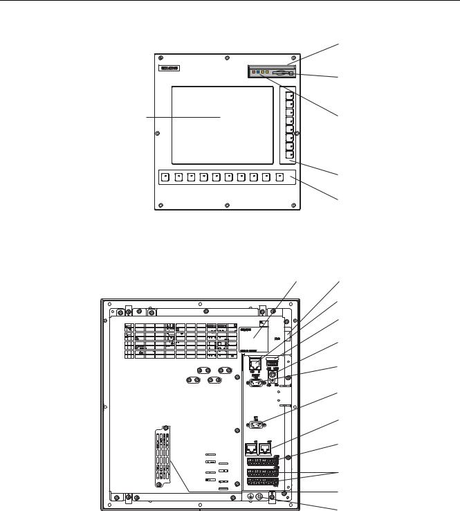
1.2Description of components
View
The illustration below shows the CNC operator panel (PCU) with its interfaces and the front panel elements.
Operating Instructions |
17 |
Operating Instructions, 12/2006, 6FC5397-0CP10-2BA0 |
Description
1.2 Description of components
)URQW YLHZ RI WKH &1& RSHUDWRU SDQHO 3&8 |
|
|
)URQW KDWFK RSHQHG |
6ORW IRU &RPSDFW )ODVK &DUG
|
(UURU DQG VWDWXV |
*UDSKLFDO GLVSOD\ |
|
|
6KRZLQJ |
|
9HUWLFDO VRIWNH\V |
|
+RUL]RQWDO VRIWNH\V |
5HDU YLHZ RI WKH &1& RSHUDWRU SDQHO 3&8 |
|
5DWLQJ SODWH |
|
|
&RQQHFWLRQ IRU |
|
3RZHU VXSSO\ ; |
|
(WKHUQHW LQWHUIDFH ; |
|
86% SRUW ; |
|
&RQQHFWLRQ IRU |
|
1& IXOO NH\ERDUG ; |
|
56 &20 SRUW |
|
; |
|
352),%86 '3 |
|
LQWHUIDFH ; |
|
'5,9( &/L4 LQWHUIDFH |
|
; DQG ; |
|
+DQGZKHHO FRQQHFWLRQ |
|
; |
|
'LJLWDO , 2 |
|
; ; |
|
Option interface |
|
X110 |
|
*URXQGLQJ VFUHZ |
|
|
Figure 1-3 Position of the interfaces and front elements on the CNC operator panel
CNC operator panel (PCU) interfaces
The PCU and its functions are described in the table below.
18 |
Operating Instructions |
Operating Instructions, 12/2006, 6FC5397-0CP10-2BA0 |

|
|
|
Description |
|
|
|
1.2 Description of components |
|
Table 1-1 |
PCU interfaces |
|
|
|
|
|
|
|
interfaces |
Function |
|
Compact flash card (CF card) slot |
50-pin slot for CF cards, and 4 LEDs |
|
|
Power supply connection |
3-pin screw-type terminal connection for |
|
|
X40 |
|
connecting the 24 V load power supply |
|
Ethernet interface |
8-pin RJ45 socket connector for connection to an |
|
|
X5 |
|
Industrial Ethernet |
|
USB interface |
4-pin USB port for connecting USB accessories |
|
|
X10 |
|
(available soon) |
|
NC full keyboard connection |
6-pin PS/2 socket for connecting the NC full |
|
|
X9 |
|
keyboard |
|
RS232 COM interface |
9-pin DSub connector for connecting a PG/PC |
|
|
X8 |
|
|
|
PROFIBUS DP interface |
9-pin DSub socket for connection to PROFIBUS |
|
|
X6 |
|
DP |
|
DRIVE–CLiQ interface |
8-pin RJ45 socket for connecting the SINAMICS |
|
|
X1 and X2 |
|
S120 drive |
|
Handwheel connection |
12-pin screw-type male connector for connecting |
|
|
X30 |
|
a max. of 2 handwheels |
|
Digital inputs/digital outputs |
12-pin screw-type male connector for connecting |
|
|
X20 and X21 |
|
the digital inputs and outputs |
|
Option interface |
48-pin female connector for connecting the |
|
|
X110 |
|
MCPA module |
Operating Instructions |
19 |
Operating Instructions, 12/2006, 6FC5397-0CP10-2BA0 |

Description
1.2 Description of components
20 |
Operating Instructions |
Operating Instructions, 12/2006, 6FC5397-0CP10-2BA0 |
interfaces |
2 |
2.1CNC operator panel interfaces
2.1.1Compact flash card (CF card) slot
Only type 1 compact flash cards can be used.
The compact flash card can be used, for example:
•for start-up data
•for NC programs
•to carry out software updates
•to store user data
•to save parameters which have been set by the user.
2.1.2Ethernet interface
A PG/PC can be connected to the Ethernet interface via a Industrial Ethernet network. The device connected must possess an Ethernet card and the appropriate software.
Industrial Ethernet is a communication network providing a transmission rate of 10/100 Mbps.
Female connector pin assignment
Identifiers: X5(IE)
Type: 8-pin RJ45 socket
|
Table 2-1 |
Pin assignment of female connector X5 |
|
||
|
|
|
|
|
|
|
Schematic view of the female connector, |
Pin |
Name |
Description |
|
|
mounting position and labeling |
|
|
|
|
|
|
|
1 |
TXP |
Transmit data + |
|
|
|
2 |
TXN |
Transmit data - |
|
|
|
3 |
RXP |
Receive data + |
|
|
|
4 |
not assigned |
- |
|
|
|
5 |
not assigned |
- |
Operating Instructions |
|
|
|
21 |
|
Operating Instructions, 12/2006, 6FC5397-0CP10-2BA0 |
|
|
|||

interfaces
2.1 CNC operator panel interfaces
Schematic view of the female connector, |
Pin |
Name |
Description |
|
mounting position and labeling |
|
|
|
|
|
|
6 |
RXN |
Receive data - |
|
|
|||
|
|
7 |
not assigned |
- |
|
|
8 |
not assigned |
- |
$ |
% |
|
|
|
; |
,( |
|
|
|
|
|
|
|
|
For additional information about the cabling options for Ethernet, contact your SIEMENS representative.
2.1.3USB port (available soon)
2.1.4RS232 COM port
A PC / programming device (PG) for data exchange with the CNC operator panel can be connected to male connector X8.
Connector pin assignment
Identifiers: X8 (RS232)
Type: 9-pin D–Sub terminal strip
Table 2-2 |
Pin assignment of connector X8 |
|
|
|||
|
|
|
|
|
|
|
Schematic |
|
Pin |
Name |
|
Description |
|
view of the |
|
|
|
German/English: |
||
female |
|
|
|
|
|
|
connector, |
|
|
|
|
|
|
mounting |
|
|
|
|
|
|
position and |
|
|
|
|
|
|
labeling |
|
|
|
|
|
|
|
|
1 |
DCD |
Received Line Signal |
|
Data carrier detect |
|
|
|
|
Detector Carrier Detector |
|
|
|
|
2 |
RxD |
Received Data |
|
Received data |
56 |
|
3 |
TxD |
Transmitted Data |
|
Transmitted data |
|
|
|
|
|
|
|
; |
|
4 |
DTR |
Data Terminal Ready |
|
Data Terminal Ready |
|
|
|
||||
|
|
|
|
|
|
|
|
|
5 |
G |
Ground |
|
Ground |
|
|
6 |
DSR |
Data Set Ready |
|
Data Set Ready |
|
|
7 |
RTS |
Request To Send |
|
Transmission request |
|
|
|
||||
|
|
8 |
CTS |
Clear To Send |
|
Ready to send |
22 |
Operating Instructions |
Operating Instructions, 12/2006, 6FC5397-0CP10-2BA0 |

|
|
|
|
|
|
interfaces |
|
|
|
|
|
2.1 CNC operator panel interfaces |
|
|
|
|
|
|
|
|
|
Schematic |
Pin |
Name |
|
Description |
|
|
view of the |
|
|
|
German/English: |
|
|
female |
|
|
|
|
|
|
connector, |
|
|
|
|
|
|
mounting |
|
|
|
|
|
|
position and |
|
|
|
|
|
|
labeling |
|
|
|
|
|
|
|
9 |
not assigned |
- |
|
- |
2.1.5PROFIBUS DP interface
The CNC operator panel (PCU) communicates with the I/O modules via the PROFIBUS DP interface.
The PROFIBUS DP protocol is used for communications.
The baud rate of the PROFIBUS DP interface is 12 Mbit/s; the baud rate cannot be changed. Converters for optical fiber cable (OLMs, OLPs) or repeaters are not permitted.
The operator panel CNC provides master functionality.
Female connector pin assignment
Designation: X6 (DP1)
Type: 9-pin D–Sub socket connector
Table 2-3 |
Pin assignment of female connector X6 |
|
||
|
|
|
|
|
Schematic view of the female |
Pin |
Name |
Description |
|
connector, |
|
|
|
|
mounting position and labeling |
|
|
|
|
'3 |
|
1 |
not assigned |
- |
|
|
|
|
|
; |
|
2 |
M24 |
|
|
|
|
||
|
|
3 |
B |
Data input/output (RS485) |
|
|
|||
|
|
4 |
RTS |
Transmission request |
|
|
5 |
M5 |
5 V reference potential |
|
|
|
|
|
|
|
6 |
P5 |
5 V power supply 90 mA, short-circuit- |
|
|
|
|
proof |
|
|
7 |
P24 |
24V power supply (teleservice) 150mA, |
|
|
|
|
short-circuit-proof, not isolated |
|
|
8 |
A |
Data input/output (RS485) |
|
|
9 |
not assigned |
- |
Operating Instructions |
23 |
Operating Instructions, 12/2006, 6FC5397-0CP10-2BA0 |

interfaces
2.1 CNC operator panel interfaces
2.1.6DRIVE-CLiQ interface
The CNC operator panel (PCU) can communicate with the "SINAMICS S" drive via the DRIVE CLiQ interface.
Female connector pin assignment
Designation: X1, X2
Type: 8-pin RJ45 socket
Table 2-4 |
Pin assignment of female connector X1 and X2 |
|
|||||
|
|
|
|
||||
Schematic view of the female connector, |
Pin |
Name |
Description |
||||
mounting position and labeling |
|
|
|
||||
|
|
|
|
|
1 |
TXP |
Transmit data + |
|
|
|
|
|
2 |
TXN |
Transmit data - |
|
|
|
|
|
3 |
RXP |
Receive data + |
|
|
|
|
|
4 |
not assigned |
- |
|
|
|
|
|
|||
|
|
|
|
|
5 |
not assigned |
- |
|
|
|
|
|
6 |
RXN |
Receive data - |
|
$ |
% |
$ |
% |
7 |
not assigned |
- |
|
|
|
|
|
|
not assigned |
|
|
|
; |
|
; |
8 |
- |
|
|
|
|
|
|
|
|
|
|
|
|
|
|
A |
not assigned |
- |
|
|
|
|
|
B |
not assigned |
- |
Blanking plate for DRIVE CLiQ interface: Molex corp., order no. 85999–3255 |
|
||||||
2.1.7Handwheel connection
Max. 2 electronic handwheels can be connected to connector X30 on the CNC operator panel (PCU).
The handwheel must meet the following requirements:
Transmission procedure: |
5 V square wave signals (TTL level or RS422) |
Signals: |
Track A as a true and negated signal (Ua1, Ua1) |
|
Track B as a true and negated signal (Ua2, Ua2) |
Max. output frequency: |
500 kHz |
Phase shift |
of Track A to Track B: 90° ±30° |
Supply: |
5 V, max. 250 mA |
Connector pin assignment
Designation: X30
Type: 12-pin connector
24 |
Operating Instructions |
Operating Instructions, 12/2006, 6FC5397-0CP10-2BA0 |
|
|
|
|
interfaces |
|
|
|
|
2.1 CNC operator panel interfaces |
Table 2-5 |
Pin assignment of connector X30 |
|
|
|
Schematic view of the connector |
Pin |
Name |
Description |
|
|
|
1 |
3P5 |
5VDC supply voltage |
|
|
2 |
G |
Ground |
|
|
3 |
1A |
Track A, handwheel 1 |
|
|
|||
|
|
4 |
X1A |
Track A_N, handwheel 1 |
|
|
5 |
1B |
Track B, handwheel 1 |
|
|
6 |
X1B |
Track B_N, handwheel 1 |
|
|
7 |
3P5 |
5VDC supply voltage |
|
|
8 |
G |
Ground |
|
|
9 |
2A |
Track A, handwheel 2 |
|
|
10 |
X2A |
Track A_N, handwheel 2 |
|
; |
11 |
2B |
Track B, handwheel 2 |
|
|
12 |
X2B |
Track B_N, handwheel 2 |
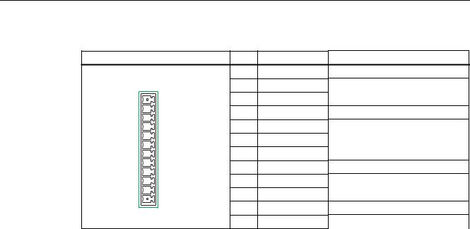
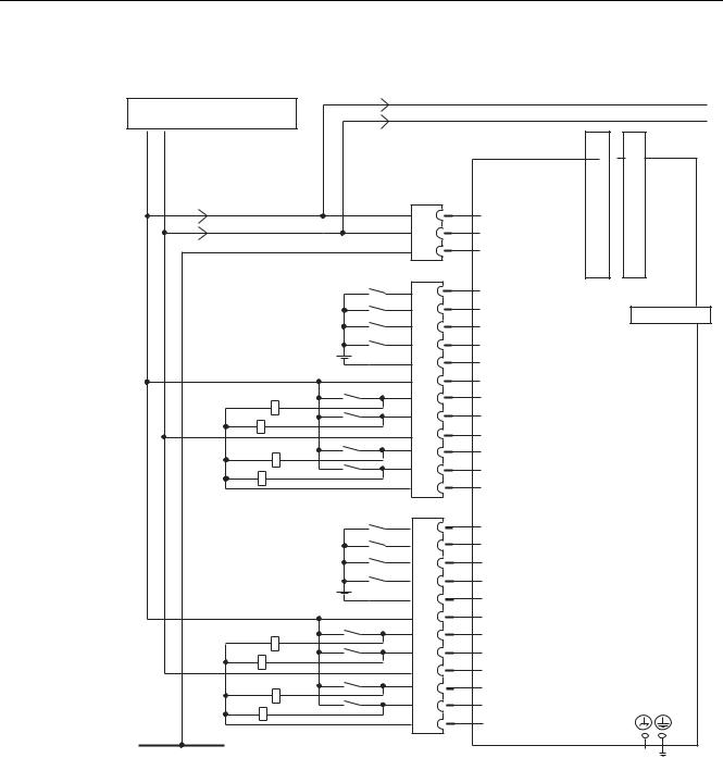
2.1.8Digital inputs/outputs
You can implement the circuit of the SINAMICS drives via digital inputs and digital outputs at connectors X20 and X21.
A maximum of 16 or 8 digital inputs and 8 digital outputs can be used.
Operating Instructions |
25 |
Operating Instructions, 12/2006, 6FC5397-0CP10-2BA0 |
interfaces
2.1 CNC operator panel interfaces
Wiring and block diagrams
|
|
|
|
|
|
|
3 |
([W SRZHU VXSSO\ |
|
|
|
|
|
|
|
|
|
|
|
|
|
|
* |
9 '& |
|
|
|
|
|
|
|
3 |
* |
|
|
'5,9(&/L46RFNHW |
|
'5,9(&/L46RFNHW |
|
|
|
; |
|
|
|
||
|
|
; |
|
|
|
|
|
|
3 |
|
9 |
|
|
|
|
|
* |
|
* |
|
|
|
|
|
3, |
|
3, |
|
|
|
|
|
|
|
|
|
|
|
|
|
|
|
', |
|
|
|
|
|
|
|
|
; |
|
; |
|
|
|
|
', |
|
|
|
|
|
|
|
|
|
|
352),%86 |
|
|
|
|
', |
|
|
|
|
|
|
|
|
|
|
; |
|
|
|
|
', |
|
|
|
|
|
|
|
0 |
|
|
|
|
|
|
|
|
2SHUDWRU SDQHO |
|
||
|
|
|
3 B |
|
|
|
|
|
|
|
|
&1& 3&8 |
|
||
|
|
|
', '2 |
|
|
|
|
|
|
|
', '2 |
|
|
|
|
|
|
|
|
|
|
|
|
|
|
|
0B |
|
|
|
|
|
|
|
|
|
|
|
|
|
|
|
', '2 |
|
|
|
|
|
|
|
', '2 |
|
|
|
|
|
|
|
0B |
|
|
|
|
|
|
; |
|
|
|
|
|
|
|
|
', |
|
|
|
|
|
|
|
', |
|
|
|
|
|
|
|
', |
|
|
|
|
|
|
|
', |
|
|
|
|
|
|
|
|
|
|
|
|
|
|
|
0B |
|
|
|
|
|
|
|
|
|
|
|
|
|
|
|
3 B |
|
|
|
|
|
|
|
|
|
|
|
|
|
|
|
', '2 |
|
|
|
|
|
|
|
', '2 |
|
|
|
|
|
|
|
0B |
|
|
|
|
|
|
|
|
|
|
|
|
|
|
|
', '2 |
|
|
|
|
|
|
|
|
|
|
|
|
|
|
|
', '2 |
|
|
|
|
|
|
|
0B |
|
|
|
|
|
|
|
|
|
|
|
|
|
(DUWKLQJ |
|
|
|
|
|
|
Figure 2-1 Connection example
Connector pin assignment
Designation: X20, X21
Type: 12-pin connector
26 |
Operating Instructions |
Operating Instructions, 12/2006, 6FC5397-0CP10-2BA0 |

|
|
|
|
|
|
|
interfaces |
|
|
|
|
|
|
|
2.1 CNC operator panel interfaces |
|
Table 2-6 |
Pin assignment of the connectors X20 and X21 |
|
||||
|
|
|
|
|
|
|
|
|
Representati |
|
Pin |
Name |
Description |
|
Technical details |
|
on |
|
|
|
|
|
|
|
|
|
1 |
DI0 |
Digital input 0 |
|
Input: |
|
|
|
2 |
DI1 |
Digital input 1 |
|
Voltage: 24VDC (20.4 ... 28.8V) |
|
|
|
|
Level: |
|||
|
|
|
3 |
DI2 |
Digital input 2 |
|
|
|
|
|
|
0 signal: -3...5 V |
|||
|
|
|
4 |
DI3 |
Digital input 3 |
|
|
|
|
|
|
1 signal: 11...30 V |
|||
|
|
|
5 |
M_3 |
Ground for DI0...DI3 |
|
Input delay: |
|
|
|
|
|
|
|
0 → 1 signal: 15 µs (typically 6) |
|
|
|
|
|
|
|
1 → 0 signal: 150 µs (typically 40) |
|
|
|
6 |
P24_1 |
24VDC Supply voltage for |
|
For the output: |
|
|
|
|
|
DI/DO0...DI/DO3 (required |
|
max. output current: |
|
|
|
|
|
for digital outputs) |
|
1 signal: 5 mA ... 0.5 A |
|
|
|
7 |
DI/DO0 |
Digital I/O |
|
Total current of all outputs: |
|
|
|
|
||||
|
|
|
|
max. 2 A (in case of simultaneous |
|||
|
|
|
|
|
|
|
|
|
; |
|
8 |
DI/DO1 |
Digital I/O |
|
|
|
|
|
|
occurrence 50 %) |
|||
|
|
|
9 |
M_1 |
Ground for |
|
|
|
|
|
|
Output delay: |
|||
|
|
|
|
|
DI/DO0...DI/DO3 |
|
0 → 1 signal: 500 µs |
|
|
|
10 |
DI/DO2 |
Digital I/O |
|
(typically 150 µs) |
|
|
|
|
|
|
|
1 → 0 signal: 500 µs |
|
|
|
11 |
DI/DO3 |
Digital I/O |
|
|
|
|
|
|
(typ. 150 µs) |
|||
|
|
|
12 |
M_1 |
Ground for |
|
|
|
|
|
|
each for RL = 60 Ohms |
|||
|
|
|
|
|
DI/DO0...DI/DO3 |
|
switching frequency: |
|
|
|
|
|
|
|
100 Hz (ohmic load) |
|
|
|
|
|
|
|
2 Hz (inductive load) |
|
|
|
|
|
|
|
For the input: |
|
|
|
|
|
|
|
Data see connector X21 |
|
|
|
|
|
|
||
|
|
|
1 |
DI4 |
Digital input 4 |
|
Input: |
|
|
|
2 |
DI5 |
Digital input 5 |
|
for the data, see connector X20 |
|
|
|
|
|
|||
|
|
|
3 |
DI6 |
Digital input 6 |
|
|
|
|
|
4 |
DI7 |
Digital input 7 |
|
|
|
|
|
5 |
M_4 |
Ground for DI4...DI7 |
|
|
|
|
|
6 |
P24_2 |
24VDC supply voltage for |
|
Output: |
|
|
|
|
|
DI/DO4...DI/DO7 (required |
|
for the data, see connector X20 |
|
|
|
|
|
for digital outputs) |
|
Input: |
|
|
|
7 |
DI/DO4 |
Digital I/O |
|
Voltage: 24VDC (20.4 ... 28.8V) |
|
|
|
|
|
|
|
Level: |
|
|
|
8 |
DI/DO5 |
Digital I/O |
|
|
|
|
|
|
0 signal: -3...5 V |
|||
|
; |
|
9 |
M_2 |
Ground for |
|
|
|
|
|
|
1 signal: 11...30 V |
|||
|
|
|
|
|
DI/DO4...DI/DO7 |
|
|
|
|
|
|
|
|
Input delay: |
|
|
|
|
10 |
DI/DO6 |
Digital I/O |
|
0 → 1 signal: 15 µs (typically 6) |
|
|
|
11 |
DI/DO7 |
Digital I/O |
|
1 → 0 signal: 150 µs (typically 40) |
|
|
|
|
|
|||
|
|
|
12 |
M_2 |
Ground for |
|
|
|
|
|
|
|
DI/DO4...DI/DO7 |
|
|
Operating Instructions |
27 |
Operating Instructions, 12/2006, 6FC5397-0CP10-2BA0 |
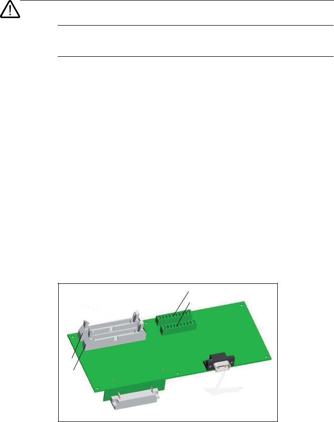
interfaces
2.2 MCPA module interfaces
Danger
The 24 V power supply is to be designed as functional extra-low voltage with protective separation in accordance with EN60204–1, Section 6.4, PELV (with G ground).
Digital inputs (PCU)
These high-speed inputs correspond to Standard IEC 1131-2/DIN EN 61131-2, characteristic curve type 2 (24 V-P-switching). Switches or proximity encoders (2- or 3-wire encoders) can be connected.
Digital outputs (PCU)
These high-speed outputs (onboard) correspond to Standard IEC 1131-2/DIN EN 61131-2 (24 V-P-switching).
See also
Setting the Profibus addresses (Page 90)
2.2MCPA module interfaces
Overview
The illustration below shows the MCPA module with its interfaces and the status display.
;
;
;
;
;
;
Figure 2-2 Position of the interfaces and of the status display on the MCPA module
28 |
Operating Instructions |
Operating Instructions, 12/2006, 6FC5397-0CP10-2BA0 |

|
|
|
interfaces |
|
|
|
2.2 MCPA module interfaces |
|
Table 2-7 |
Interfaces and status display |
|
|
|
|
|
|
interfaces |
|
Function |
|
Interface for |
|
40-pin plug connectors for connecting the machine control panel (MCP) |
|
MCP 802D sl |
|
|
|
X1 and X2 |
|
|
|
I/O interface |
|
10-pin plug connectors for connection of the power supply and of the |
|
X1020 and X1021 |
high-speed digital inputs and outputs |
|
|
Analog spindle connection |
9-pin D-Sub connector for connecting an analog spindle with directly |
|
|
X701 |
|
mounted spindle actual-value encoder |
|
Interface to the PCU |
48-pin plug connectors for connecting the MCPA module to the PCU |
|
|
X110 |
|
|
Assignment of the interface to the MCP 802D sl
Designation: X1, X2
Type: 40-pin ribbon cable connector
Table 2-8 |
Pin assignment of connectors X1 and X2 |
|
|
||||
|
X1 |
|
|
|
|
|
|
|
|
|
|
|
|
|
|
|
Pin |
Name |
|
Description |
Pin |
Name |
Description |
|
1 |
KEY1 |
|
Input bit |
2 |
KEY2 |
Input bit |
|
3 |
KEY3 |
|
Input bit |
4 |
KEY4 |
Input bit |
|
5 |
KEY5 |
|
Input bit |
6 |
KEY6 |
Input bit |
|
7 |
KEY7 |
|
Input bit |
8 |
KEY8 |
Input bit |
|
9 |
GND |
|
|
10 |
KEY9 |
Input bit |
|
11 |
KEY10 |
|
Input bit |
12 |
KEY11 |
Input bit |
|
13 |
KEY12 |
|
Input bit |
14 |
KEY13 |
Input bit |
|
15 |
KEY14 |
|
Input bit |
16 |
KEY15 |
Input bit |
|
17 |
KEY16 |
|
Input bit |
18 |
GND |
|
|
19 |
KEY17 |
|
Input bit |
20 |
KEY18 |
Input bit |
|
21 |
KEY19 |
|
Input bit |
22 |
KEY20 |
Input bit |
|
23 |
KEY21 |
|
Input bit |
24 |
KEY22 |
Input bit |
|
25 |
KEY23 |
|
Input bit |
26 |
KEY24 |
Input bit |
|
27 |
GND |
|
|
28 |
LED1 |
Output bit |
|
29 |
LED2 |
|
Output bit |
30 |
LED3 |
Output bit |
|
31 |
LED4 |
|
Output bit |
32 |
LED5 |
Output bit |
|
33 |
LED6 |
|
Output bit |
34 |
not assigned |
- |
|
35 |
not assigned |
- |
36 |
GND |
|
|
|
37 |
not assigned |
- |
38 |
not assigned |
- |
|
|
39 |
not assigned |
- |
40 |
not assigned |
- |
|
|
X2 |
|
|
|
|
|
|
|
|
|
|
|
|
|
|
|
1 |
KEY25 |
|
Input bit |
2 |
KEY26 |
Input bit |
Operating Instructions |
29 |
Operating Instructions, 12/2006, 6FC5397-0CP10-2BA0 |

interfaces
2.2 MCPA module interfaces
X2
3 |
KEY27 |
Input bit |
4 |
not assigned |
- |
5 |
not assigned |
- |
6 |
not assigned |
- |
7 |
not assigned |
- |
8 |
not assigned |
- |
9 |
GND |
|
10 |
FEED_OV_A |
Input bit |
11 |
FEED_OV_B |
Input bit |
12 |
FEED_OV_C |
Input bit |
13 |
FEED_OV_D |
Input bit |
14 |
FEED_OV_E |
Input bit |
15 |
not assigned |
- |
16 |
not assigned |
- |
17 |
not assigned |
- |
18 |
GND |
|
19 |
SPINDLE_OV_A |
Input bit |
20 |
SPINDLE_OV_B |
Input bit |
21 |
SPINDLE_OV_C |
Input bit |
22 |
SPINDLE_OV_D |
Input bit |
23 |
SPINDLE_OV_E |
Input bit |
24 |
not assigned |
- |
25 |
not assigned |
- |
26 |
not assigned |
- |
27 |
not assigned |
- |
28 |
not assigned |
- |
29 |
not assigned |
- |
30 |
not assigned |
- |
31 |
not assigned |
- |
32 |
not assigned |
- |
33 |
not assigned |
- |
34 |
not assigned |
- |
35 |
not assigned |
- |
36 |
GND |
|
37 |
not assigned |
- |
38 |
not assigned |
- |
39 |
not assigned |
- |
40 |
not assigned |
- |
Assignment of the I/O interface connectors
Designation: X1020, X1021
Type: 10-pin connector
Table 2-9 |
Pin assignment of the connectors X1020 and X1021 |
|||
|
|
|
|
|
Representation |
Pin |
Name |
Description |
|
|
|
1 |
|
|
|
|
2 |
DI0 |
high-speed digital input 0 |
|
|
3 |
DI1 |
high-speed digital input 1 |
|
|
4 |
DI2 |
high-speed digital input 2 |
|
|
5 |
DI3 |
high-speed digital input 3 |
|
|
6 |
DI4 |
high-speed digital input 4 |
|
|
7 |
DI5 |
high-speed digital input 5 |
|
|
8 |
DI6 |
high-speed digital input 6 |
|
|
9 |
DI7 |
high-speed digital input 7 |
|
|
10 |
|
Chassis ground |
|
|
|
|
|
|
|
1 |
P24 |
24VDC supply voltage |
|
|
2 |
Q0 |
high-speed digital output 0 |
|
|
3 |
Q1 |
high-speed digital output 1 |
|
|
4 |
Q2 |
high-speed digital output 2 |
30 |
Operating Instructions |
Operating Instructions, 12/2006, 6FC5397-0CP10-2BA0 |
Loading...