

Application
0
10
20
30
40
50
60
70
80
90
100
°F
0
5
10
15
20
25
30
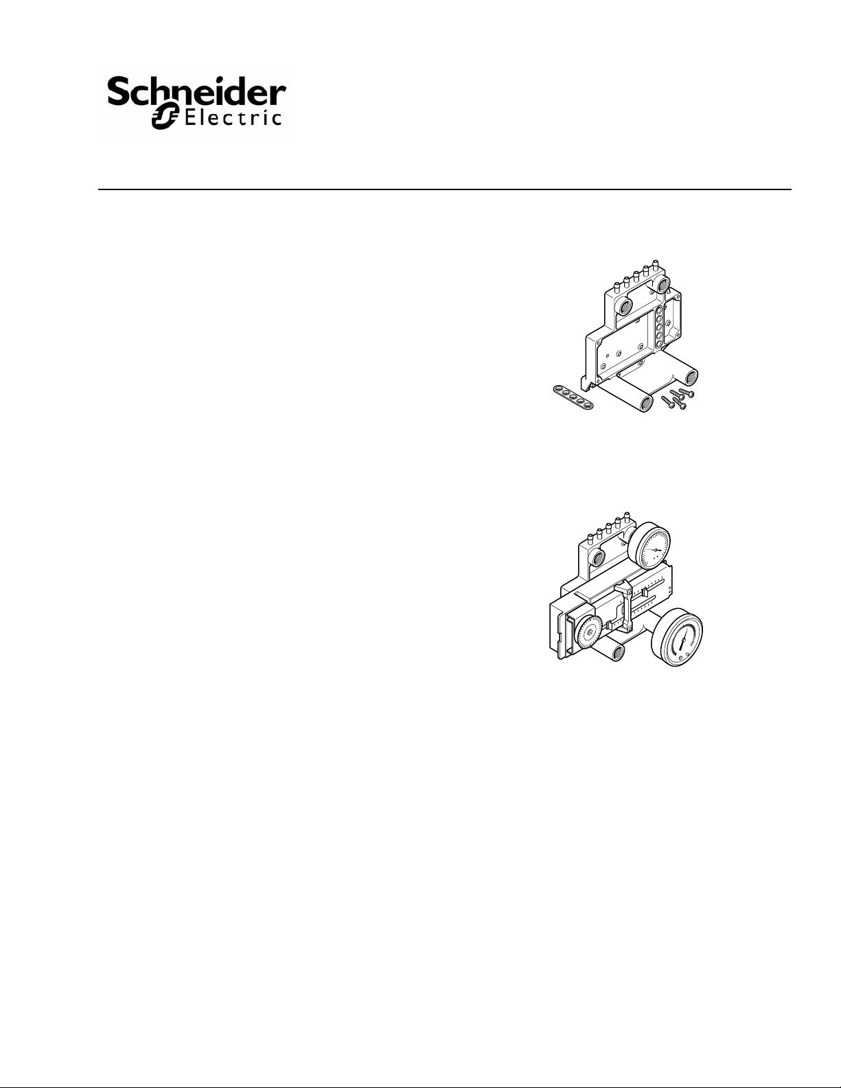
P541-BASE
P541-BASE
with one P-541 Series Receiver-Controller,
one 1-1/2" Pressure Gauge, and one 2"
Receiver-Gauge mounted
The P541-BASE is a mounting base designed to permit
stand-alone field-mounting of either the P541
(2341-501), direct acting — or the P541-RA
(2341-502), reverse acting — three-input
receiver-controller. It also provides for the mounting of
up to two receiver-gauges and two pressure gauges.
P541-BASE
Mounting Base
General Instructions
The compact size, versatility, and ample capabili
ty of a
base-mounted P541 or P541-RA receiver-controller
allows field-mounting of same for either new
construction; additions or modifications to existing
control systems; or the replacement of most existing
receiver-controllers.
Features
• Features compact size and ample capacity when
combined with a mounted P541 seri
re
ceiver-controlle
r
es
• Durable glass-filled nylon construction
• Barbed connections for 1/4 in. (6.8 mm) poly tubing
• Ports for gauges with 1/8 in. MNPT, center-back
con
nections
Applicable Literature
• P541, Receiver-Controller General Instructions,
F-23895
• P341, Receiver-Controller General Instructions,
F-23894
• Pneumatic Products Catalog, F-27383
Printed in U.S.A. 6-10 Copyright 2010 Schneider Electric All Rights Reserved. F-26081-4

SPECIFICATIONS
Construction: : Glass-filled nylon.
Maximum Air Pressure: : 30 psig (207 kPa).
Ambient Temperature Limits: :
Shipping and Storage, , -40 to 140° F (-40 to 60° C).
Operating, , 35 to 140° F (2 to 60° C).
Air Connections: : Five barbed fittings for 1/4 in. (6.4 mm) poly tubing.
Gauge Ports: : Four ports for center-back gauges with 1/8 in. MNPT fittings.
Mounting Dimensions (with P541 Series Controller and Gauges Mounted): :
5-3/8 H x 5-13/16 W x approx. 3-3/4 D in. (137 H x 148 W x approx. 95 D mm).
ACCESSORIES
See Accessories Chart, Table-1.
Table-1 Accessories Chart.
Schneider
Electric
Model No.
K541 22-171 Cover for P541 series receiver-controllers
N100-0010 21-038
N4-32 20-944
N100-2501 21-153
A253-12 2422-003
23-XX NA
A201-02 2420-001
AL-362 NA
M-101 20-983 1/8" MPT plug (for unused gauge ports)
MCS-G 22-133 Gasket (one is included with P541-BASE)
MCS-SCREW 22-134
Schneider
Electric
Uni-Line
Model No.
Description
Restrictor tee for 1/4 in. (6.4 mm) O.D. poly tubing, 1.0 SCFH
(plastic, barbed, red)
Restrictor tee for 1/4 in. (6.4 mm) O.D.copper tubing (brass
compression type)
Restrictor, in-line, for 1/4 in. (6.4 mm) O.D. poly tubing, 1.0 SCFH
(plastic, red)
Receiver-gauge, 2 in. diameter (0 to 100° F). Other ranges may
be displayed with the selection of a 23-XX series adhesive
receiver-gauge dial.
Series of adhesive receiver-gauge dials to fit A253-12 receivergauges, to indicate ranges other than 0 to 100° F (printed on dial
face).
Pressure gauge, 0 to 30 psi scale, 1-1/2 in. diameter
(Robertshaw logo)
Pressure gauge, 0 to 30 psi (0 to 200 kPa), 1-1/2 in. diameter
(Barber-Colman logo)
No. 6, 1/2 in. (13 mm) long, Plastite double-helix screw, for
attaching P541 or P541-RA receiver-controller to P541-BASE
(four included with P541-BASE)
TOOL S
Appropriate drill and drill bit for mounting screws
Appropriate screwdrivers and wrenches
2 Copyright 2010 Schneider Electric All Rights Reserved. F-26081-4

INSTALLATION
Inspection Inspect the package for damage. If damaged, notify the appropriate carrier immediately. If
undamaged, open the package and inspect the device for obvious damage. Return
damaged products.
Requirements • Piping diagrams
• Tools (not provided):
– Appropriate drill and drill bit for mounting screws
– Appropriate screwdrivers and wrenches
• Training: Installer must be a qualified, experienced technician
• Other accessories as appropriate
Caution:
• Use a refrigerated air dryer, particulate filter, and a coalescing filter to provide the
required clean, dry, oil-free air (refer to EN-123).
• The compressor oil must be non-paraffin, mineral base or naphtha base. The use of
synthetic or paraffin base oils will destroy pneumatic controls and void the warranty.
• Make all connections in accordance with the piping diagram.
• Avoid locations where excessive oil, dust, moisture, corrosive fumes or vibration is
present.
Mounting The mounting base provides for the mounting of one P541 or P541-RA receiver-controller
and four gauges having 1/8 in. MNPT, center-back connections. Refer to Figure-1.
Gauges
A selection of gauges may be installed onto the mounting base. Thread the desired gauges
into the 1/8 in. MNPT fittings and tighten, using an appropriate wrench. Refer to Figure-1.
Caution: Do not overtighten when installing a gauge or plug onto the mounting base.
Overtightening can cause the port to crack.
The gauges, and the ports to which they may be mounted, are as follows:
• Two 2 in. diameter, 3 to 15 psig (21 to 103 kPa) receiver-gauges for the primary (S) and
secondary (R) transmitter input ports.
• Two 1-1/2 in. diameter, 0 to 30 psig (0 to 207 kPa) pressure gauges for the branch output
signal port (B) and the remote con
trol-point adjustment, input signal port (C).
F-26081-4 Copyright 2010 Schneider Electric All Rights Reserved. 3

Figure-1 Installation of Receiver-Controller and Gauges on Mounting Base.
0
5
10
15
20
25
30
0
5
10
15
20
25
30
0
10
20
30
40
50
60
70
80
90
100
°F
0
10
20
30
40
50
60
70
80
90
100
°F
P541-BASE
Mounting Base
Port C
Port B
MCS-G Sealing
Gasket
A201-02 or AL-362
1-1/2 in. Pressure
Gauge
A201-02 or AL-362
1-1/2 in. Pressure
Gauge
A253-12
2 in. Receiver Gauge
P541 or P541-RA
Receiver Controller
MCS-SCREW
Double-Helix
Screw (1 of 4)
Port S
Port R
A253-12
2 in. Receiver Gauge
Barbed Fittings for
1/4 in. (6.4mm) Poly Tubing
C
R
S
M
B
Receiver-Controller
The P541 and P541-RA are both three-input controllers. The choice of a direct- or reverseacting controller is normally determined by the action and use of the final control devices
(valves, dampers, PE switches, etc.). Refer to P541, Receiver-Controller General
Instructions, F-23895, for more detailed information regarding the P541 or P541-RA
controller.
The mounting base is provided with a sealing gasket (MCS-G) and four double-helix screws
(MCS-SCREW). Mount the receiver-controller onto the mounting base as follows:
1. Install the sealing gasket over the barbed fittings on the back of the controller and push gasket down to rear surface of controller. Refer to Figure-1.
2. Install the controller onto the mounting base so that its barbed fittings are inserted into
the five sockets on the base. Internal ports within the base connect the installed
controller to the five fittings at the top of the mounting base and to the four gauge ports.
3. Secure the receiver-controller to the mounting base, using the four double-helix screws.
4 Copyright 2010 Schneider Electric All Rights Reserved. F-26081-4

Replacement of P341 Receiver-Controller
A P541 or P541-RA receiver-controller, mounted onto a P541-BASE mounting base, may
replace an existing P341 receiver-controller. When doing so, note the following:
• The bottom mounting foot position of the mounting base matches that of the P341.
• A new hole must be drilled in the mounting surface, for the upper mounting foot.
• If an existing P341 (or P340) and reversing-relay combination was originally used for
reverse-acting operation, a P541-RA controller, alone, may be used to replace both
devices. Refer to P341, Stand Alone Receiver-Controller General Instructions,
F-23894, for more detailed information regarding the P341 controller.
Connections Note: It is not necessary to cap unused barbed fittings or to plug unused gauge ports if the
corresponding barbed fitting is not used.
The mounting base features five barbed connections for 1/4 in. (6.4 mm) poly tubing. Refer
to Figure-1. The identification letters and functions of these connections are:
C Input from a remote Control point adjuster, if used
R Reset input from a secondary transmitter, if used
S Input Signal from a primary transmitter
M Main air
B Branch output
Note: Identification letters for the R and S gauge terminals are repeated at the gauge port
locations.
MAINTENANCE
FIELD REPAIR
The mounting base requires no maintenance.
Regular maintenance of the total system is recommended to assure sustained, optimum
performance.
None. Replace a damaged mounting base with a functional unit.
F-26081-4 Copyright 2010 Schneider Electric All Rights Reserved. 5

DIMENSIONAL DATA
2-1/4
(57)
1-1/16
(27)
2-3/8
(60)
4-5/8
(117)
2-3/8 (60)
2 (51)
2-5/8 (67)
3-11/16 (94)
4-7/16 (113)
Dimensions shown
are in inches (mm).
SR
RCSMB
Figure-2 Dimensions of P-541-BASE.
6 Copyright 2010 Schneider Electric All Rights Reserved. F-26081-4

3-3/4
(95)
2-9/16
(65)
2-1/2
(64)
5-3/8
(136)
5-13/16 (148)
Dimensions shown
are in inches (mm).
0
5
15
10
20
30
25
0
5
15
10
20
30
25
0
10
20
30
40
50
60
70
80
90
100
°F
0
10
20
30
40
50
60
70
80
90
100
°F
S
Figure-3 Dimensions of P541-BASE with Controller and Four Gauges mounted.
F-26081-4 Copyright 2010 Schneider Electric All Rights Reserved. 7

On October 1st, 2009, TAC became the Buildings business of its parent company Schneider Electric. This document reflects the visual identity of Schneider Electric,
however there remains references to TAC as a corporate brand in the body copy. As each document is updated, the body copy will be changed to reflect appropriate
corporate brand changes.
Copyright 2010, Schneider Electric
All brand names, trademarks and registered
trademarks are the property of their respective
owners. Information contained within this
document is subject to change without notice.
F-26081-4
 Loading...