


User Manual
Smart-UPS® RT
3000/5000/6000 VA 200-240 Vac
Tower/Rack Mount 3U
Uninterruptible Power Supply
English
2009 APC by Schneider Electric. APC, the APC logo, Smart-UPS and PowerChute are owned by Schneider Electric
Industries S.A.S., American Power Conversion Corporation, or affiliated companies. All other trademarks are the property of
their respective owners.
990-1289E 04/2010


Introduction
The APC by Schneider Electric Smart-UPS RT is a high-performance, uninterruptible power
supply (UPS) that provides protection for electronic equipment from utility power blackouts,
brownouts, sags and surges. The UPS filters small utility line fluctuations and isolates electronic
equipment from large disturbances by internally disconnecting from utility line power. The UPS
provides continuous power from the internal battery until utility power returns to safe levels or the
battery is fully discharged.
INSTALLA TION
Read the Safety Guide before installing the UPS.
Unpacking
Insp ect the UPS upon receip t. Notify the carr ier and deal er if there is damage.
The packaging is recyclable; save it for reuse or dispose of it properly.
Check th e pa ckage con tents:
UPS (with battery modules disconnected)
Front bezel
Literature kit containi ng :
Product documentation, Safety Guide,
and Warranty Information
Smar t- UPS RT Us er Manu als CD
Specifications
TEMPERATURE
PERATING
O
TORAGE
S
MAXIMUM
ELEVATION
O
PERATING
TORAGE
S
HUMIDITY
WEIGHT
UPS
UPS WI TH
PACKAGING
32° to 104° F (0° to 40° C)
5° to 113° F (-15° to 45° C) charge the UPS
battery every six months
10,000 ft (3,000 m)
50,000 ft (15,240 m)
0 to 95% relative humi d ity
120 lbs (55 kg)
140 lbs (64 kg)
Software CD
Seri al cable
3000 VA XLI models: three output p ower cords,
two input power cords
5000/6000 VA XLI models: six output power
cords, Network Management Card
documentation
Thi s unit i s desi gned for i ndoor use
only. Select a location sturdy enough to
handle the weight.
Do not operate the UPS wher e there is
excessive dust or the temperature and
humidity are outside the specified limits.
Ensure that the air vents on the fron t
and rear of the UPS are not blocked.
.
1
Wiring and Connecting the UPS
5000/6000 VA XLI MOD ELS ONLY: HARDWIRING INSTRUCTIONS
• Wiring mu st be p erform ed by a qu alified electri cian.
• Install a high magnetic 30/32 A utility circuit breaker.
• Adhere t o all na tional an d l oca l electrical codes.
• Use #10 AWG gauge (5 mm
1. Switch the utility circuit breaker OFF.
2. Remove the input access panel.
3. Remove circular knockout.
2
) wire.
4. Run #10 AWG gauge (5 mm
2
) wire thr ough the acces s panel, and connect the wires to the
terminal bloc k (green : grou nd, brown : hot , blue: neutral ). Use an appropriate str a in r el ief (not
included).
5. Switch the utility circuit breaker ON.
6. Check li ne v oltages.
7. Replace t he access panel.
2

C
ONNECTING THE BATTERY MO DUL E S AND ATTACHING THE FRONT BEZEL
.
3
B
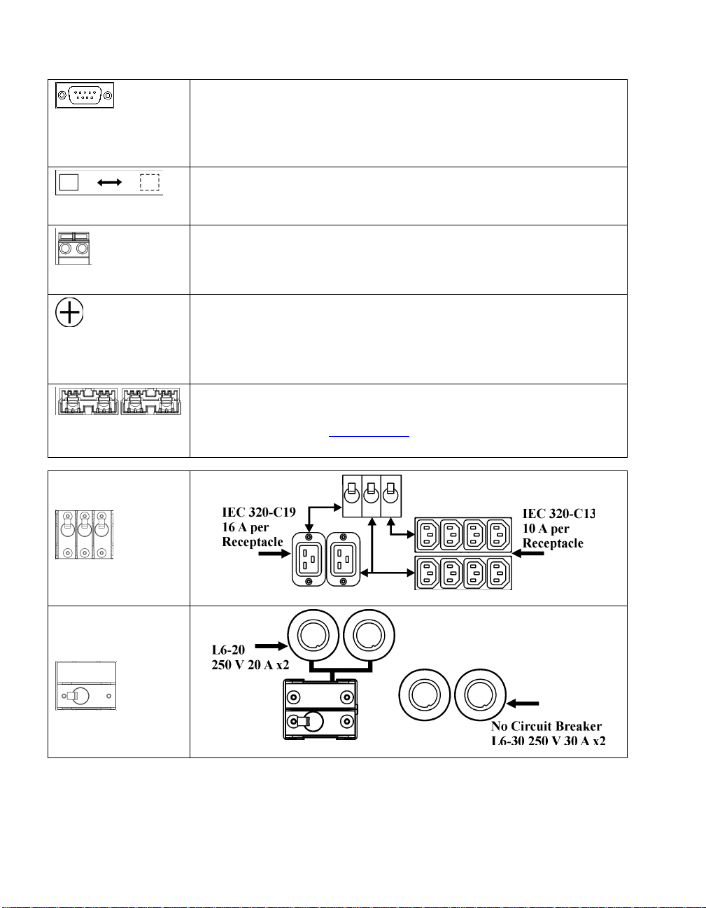
ASIC CONNECTORS
serial com
normal bypass
EPO terminal
TVSS screw
external bat t ery
pack connecto r
5000/6000 VA
XLI models
Power management software and interface kits can be used with the UPS.
Use only interface kit s supplied or approved by APC.
Any other serial interface cable will be incompatible with the UPS
connector.
Manual bypass enables the user t o manually put con nected eq u ipment in to
bypass mode.
Emergency Power Off terminal allows the user to connect the UPS to the
central EPO system.
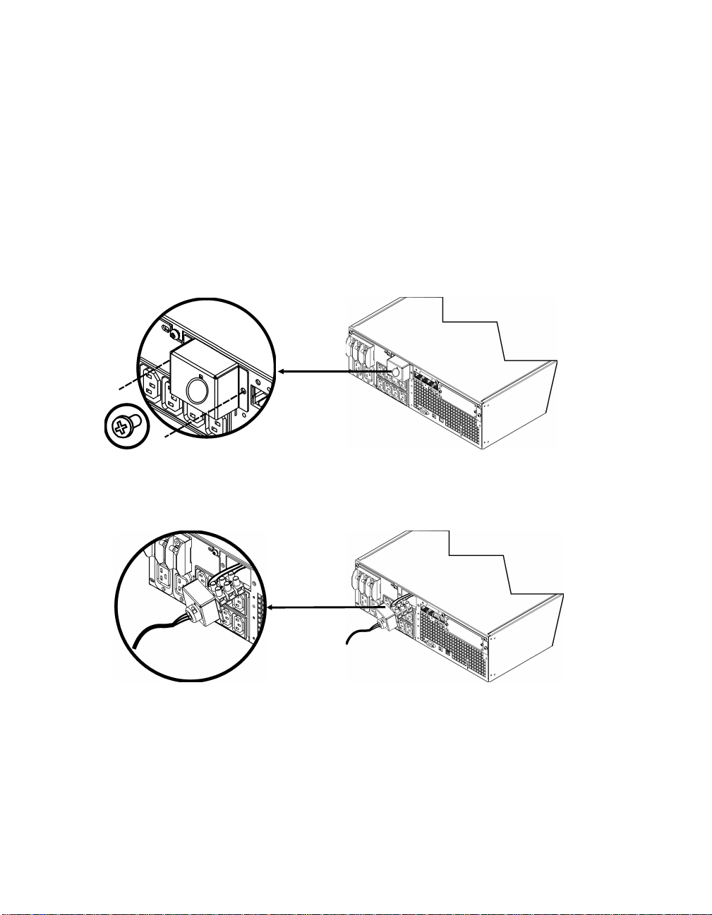
The UPS feat ures a tr ansien t vol tage surge-su p pression ( TVSS) scr ew for
connectin g the gr ound lead on surge suppre s s ion de vices such as teleph one
and network l i ne pr otect ors.
When connecting grounding cable, disconnect the unit from the utility
power outlet.
Opti onal external batt ery packs provide ext ended runtime during power
outages. These units support up to ten external battery packs.
See th e AP C Web si te, www.apc.com
for the informa tion on th e ex ternal
battery pack, SURT192XLBP.
output circuit
breakers
3000/5000/6000 VA
XLJ/XLT/XLTW
models
output circuit
breaker
4

C
ONNECTING EQ UIPME NT AND POWER TO THE UPS
1. Connect equipment to the UPS (cables not included for XLJ/XLT/XLTW models).
2. Avoid using extension cords.
• 3000 VA XLJ/XLT/XLTW/XLI and 5000/6000 VA XLJ/XLT/XLTW models: Using a power
cord, pl ug the UPS int o a two-pole, three-wire, grounded receptacle only.
• 5000/6000 VA XLJ and 6000 VA XLT models: To draw full power from the UPS have a
qualified electrician cut off the input plug and hardwire the UPS to the appropriate power
panel.
3. Turn on a ll connected equip ment. To use the UPS as a mas t er ON /OFF swit ch , ensur e all
connected equipment is switched ON. The equipment will not be powered until the UPS is
turned on.
4. To power u p the UPS press the
• The UPS bat tery charges wh en it is connected to utility power. The ba ttery char g es to 90%
button on t he fr ont panel.
capacity during the first three hours of normal operation . Do not expect full battery run
capability during this initial charge period.
®
5. For add itional computer system securit y, install PowerChute
Business Edition Smart-UPS
monitoring software.
PTIONS
O
Refer to the APC Web si te, www.apc.com
External Battery Pack SURT192XLBP
Rail Kit S URTRK2
Isolation Transformer
Service Bypass Panel
for a va ilable a cces s ories.
.
5

OPERATION
Load
SMART-UPS RT FRONT DISPLAY
Indicator Description
Online
The Online LED illuminates when the UPS is drawing utility power and perfor ming
double conversion to supply power to connected equipment.
On Battery
The UPS is supplyin g battery power to the connected equipment.
Bypass
The Bypass LED illuminates indicating that the UPS is in bypass mode. Utility
power is sent directly to connected equipment during bypass mode operation.
Bypass mode operation is the result of an internal UPS fault, an overload condition
or a user in itiated com mand either throu gh an access ory or the man u al bypass
switch. Batter y operation is not available while the UPS is in bypass mode. Refer to
Troubleshooting in this manual.
Battery Charge
Fault
Overload
The UPS det ects an in ternal fault.
Refer t o Troubleshooting in this manual.
An overload condition exists. See Troubleshooting.
Replace
Battery
The bat tery is di scon nected or must be r epl aced. See Troubleshooting.
Feature Function
Power On
Pre s s thi s button to t urn on t he UPS . (Se e be low for a dditiona l capabilities .)
Power Off
Press this button to turn off the UPS.
6

Feature Function
Cold Start
When there is no utility power and the UPS is off, press and hold the
power u p th e UPS and conn ected equipment.
The UPS will emit two beeps. During the second beep, release the button.
Self-Test
Automatic: The UPS performs a self-test automatically wh en turned on, and every
two weeks t herea ft er (by default). D ur ing the self- test, the UPS briefly operates the
conn ected equipment on ba ttery.
Manual: Press and hold the
Diagnostic Utility Voltage
button to
button for a few seconds to initiate the self-test.
The UPS has a diagnostic feature that displays the utility voltage. Plug
the UPS into the normal utility power.
The UPS starts a self-test as part of this procedure. The self-test
does not affect the voltage display.
Press and hold the
display. After a few seconds th e five-LED, B attery Charge
button to view the utility voltage bar graph
display
on the right of the front panel shows the utility input voltage.
Refer to the figure at left for the voltage reading (values are not listed
on the UPS).
The di s pl ay indicates the vol tage is bet we en the displayed va lue on the
list and the next higher value.
On Battery Operation
The UPS switches to battery operation automatically if the utility power fails. While running on
battery, an alarm beeps four times every 30 seconds.
Press the
supply power to the connected equipment until the battery is fully discharged.
When 2 minutes of run time remain the UPS emits a continuous beeping. If PowerChute is not being
used, files must be manually saved and the computer must be turned off befor e the UPS fully
discharges the battery.
The UPS bat tery li fe differs ba s ed on usage an d environment. Refer to www.apc.com
runtimes.
.
7
button to silence this alarm. If the utility power does not return, the UPS continues to
, for on ba ttery

USER CONFIGURABLE ITEMS
NOTE: SETTINGS ARE MADE THROUGH SUPPLIED POWERCHUTE SOFTWARE OPTIONAL SMART SLOT
ACCESSORY CARDS OR TERMINAL MODE.
ACTORY
FUNCTION
F
EFAULT
D
Automatic Self-Test Every 14 days
(336 hours)
U
SER SELECTABLE
CHOICES
Every 7 days(168 hours),
14 days (336 hours)
On Startup Only,
No Self-Test
ESCRIPTION
D
Set the interval at which the
UPS will execute a self-tes t.
UPS ID UPS_IDEN Up to eight characters to
define the UPS
Date of Last Battery
Replacement
Manu f actu re Date Dat e of
Battery Replacement
mm/dd/yy
Minimum Capaci ty
Before R et urn from
0 percent 0, 15, 25, 35, 50, 60, 75,
90 percent
Shutdown
Alarm Delay After
Line Failure
5 second delay 5 or 30 second delay
At L o w Ba tter y
Never
Shutdown Delay 20 seconds 0, 20, 60, 120, 240, 480,
720, 960 seconds
Duration of
Low Battery Warning.
2 minutes
PowerChute
software provides
2, 5, 7, 10, 12, 15, 18,
20 minutes
automatic,
unattended
shutdown when
approximately 2
minutes of battery
operated runtime
remains.
Uniquely identify the UPS, (i.e.
server na m e or location ) for
network m anagem ent p urpos es.
Reset this date when you replace
the battery modules.
Following a low-battery
shutdown, the bat te ry modules
will be charged to the specified
percentage bef ore powering
connected equipment.
Mute ongoi ng ala rms or di sabl e
all alarms permanently.
Set the interval between the time
when the UPS rec eives a
shutdown command and the
actual shutdo w n .
The low battery warning beeps
are continuous when two
minutes of run time remain.
Change the warning interval
default to a higher setting if the
operating system requires a
longer interval for shutdown.
Synchronized Turn-on
Delay
High Bypass Point
0 seconds 0, 20, 60, 120, 240, 480,
720, 960 seconds
+10% of
output volta ge
+5%, +10%, +15%,
+20%
setting
8
The UPS will wait t he sp e cified
time after the return of utility
power before turn-on (to avoid
branch circuit overloa d).
Maximum voltage tha t t he UPS
will pass to connected
equipment during internal
bypas s ope ration.

NOTE: SETTINGS ARE MADE THROUGH SUPPLIED POWERCHUTE SOFTWARE OPTIONAL SMART SLOT
ACCESSORY CARDS OR TERMINAL MODE.
ACTORY
FUNCTION
F
EFAULT
D
Low Bypass Point -30% of output
voltage setting
U
SER SELECTABLE
CHOICES
ESCRIPTION
D
-15%, -20%, -25%, -3 0% Minimum volta ge that the UP S
will pass to connected
equipment during internal
bypas s ope ration.
Output Voltage XLJ models:
200 VAC
XLT models:
208 VAC
XLI models:
230 VAC
XLTW models:
220 V
Outpu t F r equency Automatic
50 ± 3 Hz or
60 ± 3 Hz
Number of
1 Number of Connected
Battery Packs
XLJ models:
200 VAC
XLT models:
200, 208, 220, 230,
240 VAC
XLI models:
200, 208, 220, 230,
240 VAC
XLT/XLTW models:
200, 208, 220, 230,
240 VAC
50 ± 3 Hz
50 ± 0.1 Hz
60 ± 3 Hz
60 ± 0.1 Hz
Internal Battery Packs,
(two modules per pack)
Allows the user to select the
UPS output voltage while
online.
Sets the allowable UPS output
frequency. Whenever possible,
the output frequency tracks the
input frequency.
Defines the numbe r of internal
and extern al connecte d battery
pack s for proper r un time
prediction.
ONNECTING THE EPO (EMERGENCY POWER OFF) OPTION
C
The out p u t p ower can be disabled in an em er gency by clos ing a swit ch connected to th e EP O .
Adhere to National and local electrical codes when wiring the EPO.
EPO
switch
The EPO switch is internally powered by the UPS for use with non-powered switch circuit breakers.
The EP O circuit i s con s idered a Cl ass 2 circu it, (UL, CSA s tandard s) and a SELV circuit (I EC
standard).
.
9

Both Class 2 and SELV circui ts must be isol ated from all primary circu itry. Do not connect any
circuit to the EPO terminal block unless it can be con firmed that the circuit is Class 2 or SELV.
If cir cu it standard cannot be confirmed, use a conta ct closur e swi tch.
Use one of the follo wing ca bl e typ es to conn ect the UPS to t he EPO swit c h :
• CL2: Class 2 cable for general use
• CL2P: Plen um cable for u s e in d u cts, plenu ms, and other spaces used for en vironmen tal air.
• CL2R: Riser cable for u se in a vertical run in a fl oor to floor s haft.
• CLEX: Limited use ca ble for use in d wel l ings an d for u s e in raceways.
• For installation in Canada: Use only CSA certified, type ELC (extra-low voltage con trol cable).
ERMINAL MODE TO CONFIGURE UPS PARAMETERS
T
3000 VA models:
Terminal Mode is a menu driven interface that enables enhanced configuration of the UPS.
Connect the ser ial cable to the serial com conn ector on the back of th e UPS.
1. EXIT the PowerCh ute Business Edi tio n us ing the follo wi ng steps :
• From the Desktop, go to Start => Settings => Control Panel => A dministrative Tools =>
Services.
• Select PCBE Server and PCBE Agent – righ t click the mou s e and sel ect Stop.
2. Open a terminal program. Example: HyperTerminal
• From the Desktop, go to Start => Programs => Accessories => Communication
=>HyperTerminal.
3. Double-click on the HyperTerminal icon.
• Follow the prompts to ch oose a n ame and sel ect an icon. Disregard the messa g e, “...must
install a modem,” if it is displayed. Click OK.
• Select the COM port th at is conn ected to your UPS. Th e port sett ings are:
9 bits per second - 2400
9 data - bits 8
9 parity - none
9 stop bit - 1
9 flow control - none
• Press ENTER
4. Example for setting the number of external battery packs (SURT192XLBP):
Once the blank ter minal win dow is open, follow these steps to enter th e n um ber of batt ery packs:
• Press ENTER to initiate terminal mode. Follow the prompts:
• Press 1 to modify UPS Settings. Press e (or E) to modify the number of battery
packs. Enter the number of batter y packs, including the internal battery pack
(Number of pa cks: 1= inte rna l battery mod ule, 2 = 1 SURT 192XLBP,
3 = 2 SURT192XLBP, etc.).
Press ENTER.
• Fol low t he prompts.
5. Exit th e termina l progra m.
10

5000/6000 VA models:
Terminal Mode is a menu driven interface that enables enhanced configuration of the UPS.
Connect the ser ial cable t o the seria l p or t on the back of t he UPS.
1. Open a terminal program. Example: HyperTerminal
• From the Desktop, go to Start => Programs => Accessories => Communication
=>HyperTerminal.
2. Double-click on the HyperTerminal icon.
• Follow the prompts to ch oose a n ame and sel ect an icon. Disregard the messa g e, “...must
install a modem,” if it is displayed. Click OK.
• Select the COM port th at is conn ected to your UPS. Th e port sett ings are:
9 bits per second - 2400
9 data - bits 8
9 parity - none
9 stop bit - 1
9 flow control - none
• Press ENTER
3. Example for setting the number of external battery packs (SURT192XLBP):
Once the blank ter minal win dow is open, follow these steps to enter th e n um ber of batt ery packs:
• Pr ess ENTER to initiat e ter minal m od e. Press ENTER multiple times, until the prompt User
Name: is displayed. Follow the pr ompts. Type slowly, waiting until each character appears
on the screen prior to typing the next character .
Network Management Card defaults:
• User Name: ap c
• Password: apc
• Press 1 and ENTE R to select Device Manager.
• Select the model by enter ing the corresponding num ber, then press ENTE R.
• Press 3 and ENTER to select Configuration.
• Pr ess 1 an d E NT ER to select Batter y.
• Press 2 and ENTER to change the Batter y Settings.
• Type in the num ber of external battery packs ( four bat t ery modules p er pack) , then
pr e s s E N T ER. (Numbe r of packs : 1= intern al battery modu le,
2 = 1 SURT192XLBP, 3 = 2 SURT192XLBP, etc.)
• Pr ess 3 an d ENTER to accept the changes.
• Press ESC multiple times (5) to return to the main menu.
• Press 4 and ENTER to log out.
.
11

MAINTENANCE AND TRANSPORT
Replacing the Batter y Mod ule
This UPS has an easy to repla ce, h ot -swappa bl e battery module. Replacement is a safe p rocedure,
isola ted from el ectrica l hazards . Y ou may leave the UPS and connected eq u ipmen t on during the
procedu re. See your deal er or contact AP C at th e Web site, www.apc.com
replacemen t ba ttery modu les.
The bat tery replacemen t procedure must in clude repl acing all ba ttery modu les in th e UPS and
conn ected external battery pack(s).
Once the battery(s) are disconnected, the connected equipment is not protected
from power outages.
Be careful during ba t tery re pla ce ment , the ba t ter y modules are heavy.
Be sure to deliver spent batteries to a recycling facility or ship to the manufacturer
in the replacement battery packing material.
REMOVING BATTERY MODULES
for information on
X Y Z
[
\
12

R
EPLACING BATTERY MODULES
X Y
Z [ \
] ^ _
Disconnecting the Battery for Transport
Always DISCONNECT THE BATTERY(s) before shipping in compliance with U.S.
Department of Transportation (DOT) and IATA r egulations.
The battery(s) may remain in the UPS.
1. Shut d own an d d isconnect any equipment att ached t o the UPS.
2. Shut down and disconnect the UPS from the power supply.
3. Unplu g the battery conn ectors. Refer to Replacing Battery modules in this manual.
For shipping instruct ions contact APC at the Web site, www.apc.com
.
.
13

TROUBLESHOOTING, SERVICE, AND WA RRANTY INFORMATION
Use the table below to solve minor installation and oper ation problems. Refer to the APC Web site,
www.apc.com
for a ss istance wi th compl ex UPS p roblems.
PROBLEM AND POSSIBLE
AUSE
C
S
OLUTION
UPS WILL NOT TURN ON
Batt ery not connected properly. Check that the batter y connectors are full y enga ged.
button not pushed. Press the button once to power the UPS and the connected equipment.
UPS not connected to utility
power supply.
Very low or no utility voltage. Check the utility power supply to the UPS by plugging in a table lamp. If the
Check that the power cable from the UPS to the utility power supply is securely
connected at both ends.
light is very dim, have the utility voltage checked.
UPS WILL NOT TURN OFF
button not pushed. Press the button once to turn the UPS off.
Internal UPS fault. Do not attempt to use the UPS. Unplug the UPS and have it serviced
immediately.
UPS BEEPS OCCASIONALLY
Normal UPS op erat ion when
running on battery.
None. The UP S is protecting the connected equipment.
UPS DOES NOT PROVIDE EXPECTED BACKUP TIME
The UPS battery(s) are weak
due to a recent outage or
battery(s) are near the end of
their service life.
FRONT PANEL LEDS FLASH SEQUENTIALLY
The UPS has been shut down
remotely through software or an
optional accessory card.
ALL LEDS ARE OFF AND THE UPS IS PLUGGED INTO A WALL OUTLET
The UPS is shut down and the
battery is discharged from an
extended outage.
BYPASS AND OVERLOAD LEDS ILLUMINATE, UPS EMITS A SUSTAINED ALARM TONE
The UPS is o verloaded The con nected equipment exceeds the speci fied “maximum l oad” as defined in
Charge the battery(s). Battery modules require recharging after extended outages.
They wear faster when put into service often or when operated at elevated
temperatures. If the battery(s) are near the end of their service life, consider
replacing the battery(s) even if the Replace Battery LED is not illuminated.
None. The UPS will restart automatically when utility power returns.
None. The UPS will return to normal operation when the power is restored and
the battery has a sufficient charge.
Specifications on the APC Web site, www.apc.com
The alarm remains on until the overload is removed. Disconnect nonessential
equip ment from the UP S to eliminate the overloa d cond ition.
.
14

PROBLEM AND POSSIBLE
AUSE
C
BYPASS LED ILLUMINATES
The bypass switch has been
turned on manually or through
an accessory.
FAULT AND OVERLOAD LEDS ILLUMINATE, UPS EMITS A SUSTAINED ALARM TONE
The UPS has ceased sending
power to connected equipment.
If byp ass is the chosen mode of operation, ignore the illuminat ed LED.
If bypass is not the chosen mode of operation move the bypass switch on the
back of the UPS, to the normal position.
The connected e quipm ent exceeds the speci fied “maximum l oad” as defined in
Specifications on the APC Web site, www.apc.com
S
OLUTION
.
Disc onnect non essential equipment from the UPS to elimin ate the overload
condition.
Pres s the OFF button, then the ON button to r estore power to connected
equipment.
FAULT LED ILLUMINATES
Internal UPS fault. Do not attempt to use the UPS. Turn the UPS off and have it serviced
immediately.
REPLACE B ATT ERY LED ILLUMINATES
Replace Battery LED flashes and
Check that the battery connectors are fully engaged.
shor t beep is emit ted every two
seconds to indicate the battery is
disconnected.
Weak battery. Allow the battery to recharge for 24 hours. Then, perform a self-test. If the
problem persists after recharging, replace the battery.
Failure of a battery s elf-t est. The UPS emits short b eeps for one minute and the Replace Battery LED
illuminates. The UPS repeats t he alarm every five hours. Perform the self-test
procedure after the battery has charged for 24 hours to confirm the Replace
Battery condition. The alarm stops and the LED clears if the battery passes the
self-test.
UPS OPERATES ON BATTERY ALTHOUGH NORMAL LINE VOLTAGE EXISTS
Very high, low, or distorted line
voltage. Inexpens ive fuel
powered generators can distort
the voltage.
Move the UPS to a different outlet on a different circuit. Test the input voltage
with the utility voltage display.
DIAGNOSTIC UTILITY VOLTAGE
All five LEDs are illuminated The line voltage is extremely high and should be checked by an electrician.
There is no LED illumination If the UPS is plugged into a properly functioning utility power outlet, the line
voltage is ext r e m el y l ow.
ONLINE LED
There is no LED illumination The UPS is running on battery, or it is not turned on.
The LED is blinking The UPS is running an internal self-test.
.
15

Service
If the UPS requires service do n ot return it to th e dealer. Follow these steps:
1. Review the problems discussed in th e Troubleshooting section of this manual to eliminate
comm on problems.
2. If the problem persists, contact APC Customer Support through the
APC Web sit e, www.apc.com
• Note the model n umber of the UPS, the serial number located on th e back of the uni t, and th e
date purchased. If you call APC Customer Support, a technician will ask you to describe the
problem and attempt to solve it over the phone. If this is not possible, the technician will
issue a Return ed Material Authorization Number (RMA#).
• If the UPS is und er warranty, repairs are free.
• Procedures for servicing or returning products may vary internationally. Refer to the APC
Web sit e for country specific instructions.
3. Pack the UPS in it s original packaging.
• If the original packing is not available, refer to the APC Web site, www.apc.com
information about obtaining a new set.
• Pack the UPS prop erl y t o avoid damage in transit. Never us e Styrofoam bead s for
packaging. Damage sustained in transit is not covered under warranty.
Always DISCONNECT THE BATTERY(S) before shipping in compliance with U.S.
Department of Transportation (DOT) and IATA r egulations.
The battery(s) may remain in the UPS.
.
for
4. Mark th e RMA # on the outside of the pa ck age.
5. Return the UPS by insured, prepaid carrier to the address given to you by Customer Support.
Limited Warranty
American Power C onversion (APC) warrants its products to be free from defects in materials and workmanship for a period of
two years from the dat e o f purchase. Its obligat io n und er this warranty is limite d to repairing or repla cing , at it s own sol e
option, any such de fe ct ive pr oduct s. T o ob t a in servi c e under wa r ra nty you must obt a in a Returned Ma t er ial Au th or izati on
(RMA) number from cu st omer support. Product s mu st be r etu r ned wit h trans portation charges pr e pa id and must be
accompanied by a brief description of the problem encounter ed and proof of da te and place of purchase. This warranty does
not apply to equipment that has been damaged by accident, negligence, or misapplication or has been altered or modified in
any way. This warranty applies only to the original purchaser who must have properly registered the product within 10 days of
purchase.
EXCEPT AS PROVIDED HEREIN, AMERICAN POWER CONVERSION MAKES NO WARRANTIES, EXPRESSED OR
IMPLIED, INCLUDING WARRANTIES OF MERCHANTABILITY AND FITNESS FOR A PARTICULAR PURPOSE.
Some states do not permit limitation or exclusion of implied warranties; therefore, the aforesaid limitation(s) or exclusion(s)
may not apply to the purchaser.
EXCEPT AS PROVIDED ABOVE, IN NO EVENT WILL APC BE LIABLE FOR DIRECT, INDIRECT, SPECIAL,
INCIDENTAL, OR CONSEQUENTIAL DAMAGES ARISING OUT OF THE USE OF THIS PRODUCT, EVEN IF
ADV ISED OF THE POSSIBILITY OF SUCH DAMAGE. Spe cifically , APC is n o t liable fo r a n y costs, such as lost profits or
revenue, loss of equipment, loss of use of equipmen t, loss of software, l oss of data, costs of substitutes, claims by third parties,
or othe rwise.
16
REGULATORY
Radio Frequ enc y War ni n gs
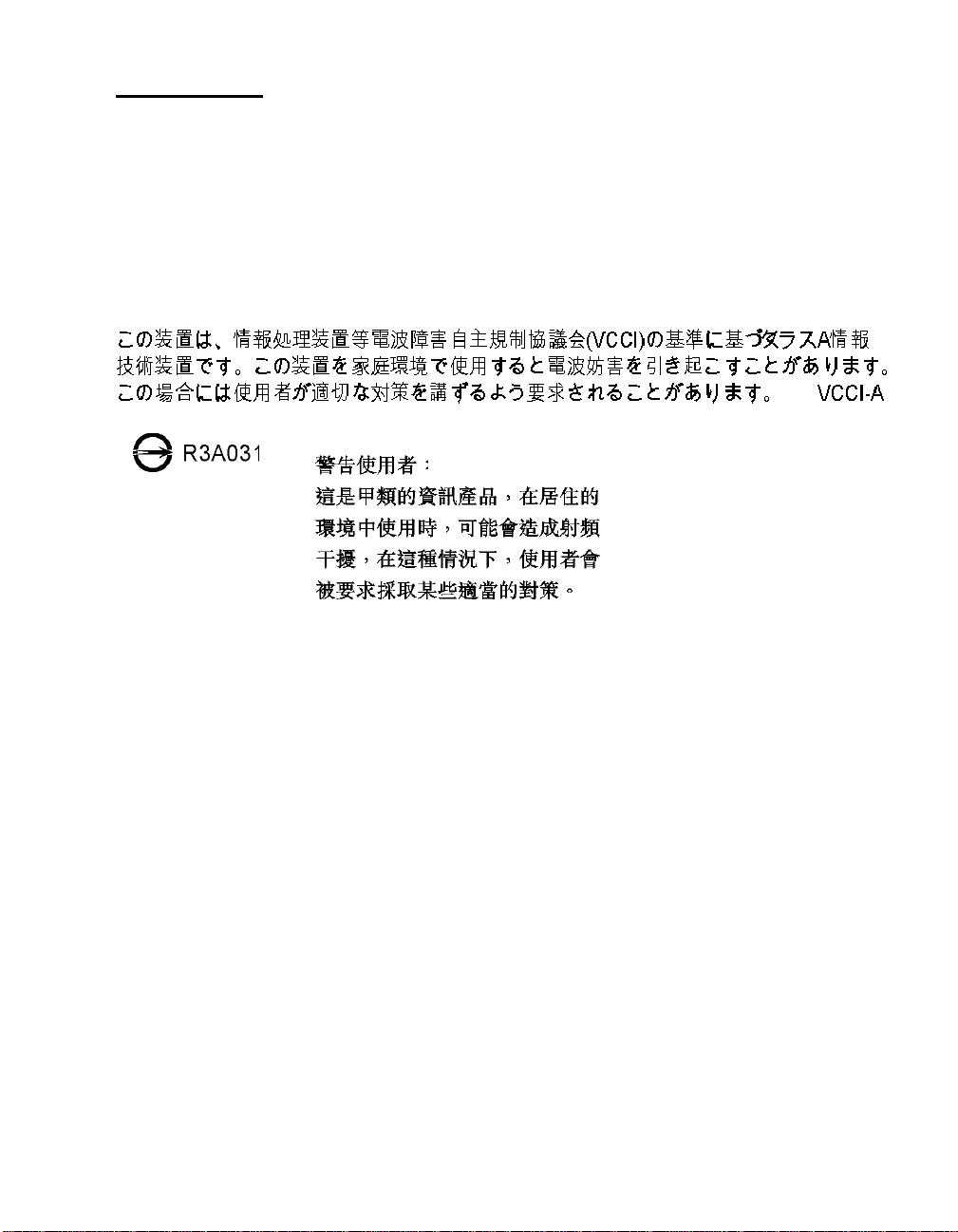
This equipment has been tested and found to comp ly with the limi ts f or a Class A digital device, pursuant to part 15 of the
FCC Rules. These limits are designed to provide reasonable protection against harmful interference when the equipment is
operated in a commercial environment. This equipment generates, uses, and can radiate radio frequency energy and, if not
installed and used in accordance with the instruction manual, may cause harmful interference to radio communications.
Operatio n o f this equipment in a resi dential area is li k ely to cause h armful inte rference. The user is responsible for correcting
the interferen ce.
Shi eld ed s ignal ca bl es must be used with thi s product to en sure complian ce wi th the Cla s s A FCC
limits.
APC Worldwide Customer Support
Customer support for this or any other APC product is available at no charge in any of the following
ways:
• Refer to th e APC Web site to access documents in the APC Knowledge Base and to submit
customer support requests.
• www.apc.com (Corporate Headquarters)
Connect to loca lized APC Web si tes for specific countries, each of wh ich provid es cu s tomer
support information.
• www.apc.com/support/
Global support searching APC Knowledge Base and using e-support.
• Contact an APC Customer Support center by telephone or e-mail.
Local, country-specific cen ters:
go to www.apc.com/support/contact for infor mation.
Con tact the APC represen tat ive or ot her distribu tor from whom you purchas ed your APC produ c t for
information on how to obtain local customer support.
.
17
 Loading...