


Schneider Electric SW 4024, SW 4048, SW 2524 User Manual
Conext™ SW Inverter/Charger
Conext SW 2524 120/240 Split-phase (865-2524)
Conext SW 4024 120/240 Split-phase (865-4024)
Conext SW 4048 120/240 Split-phase (865-4048)
Owner’s Guide
975-0638-01-01 Rev G
9-2018
solar.schneider-electric.com


Conext SW Inverter/Charger
Conext SW 2524 120/240 Split-phase (865-2524)
Conext SW 4024 120/240 Split-phase (865-4024)
Conext SW 4048 120/240 Split-phase (865-4048)
Owner’s Guide
http://solar.schneider-electric.com

Copyright and Contact
Copyright © 2012-2018 Schneider Electric. All Rights Reserved. All trademarks are owned by Schneider Electric
Industries SAS or its affiliated companies.
Exclusion for Documentation
UNLESS SPECIFICALLY AGREED TO IN WRITING, SELLER
(A) MAKES NO WARRANTY AS TO THE ACCURACY, SUFFICIENCY OR SUITABILITY OF ANY TECHNICAL OR OTHER INFORMATION
PROVIDED IN ITS MANUALS OR OTHER DOCUMENTATION;
(B) ASSUMES NO RESPONSIBILITY OR LIABILITY FOR LOSSES, DAMAGES, COSTS OR EXPENSES, WHETHER SPECIAL, DIRECT,
INDIRECT, CONSEQUENTIAL OR INCIDENTAL, WHICH MIGHT ARISE OUT OF THE USE OF SUCH INFORMATION.THE USE OF ANY
SUCH INFORMATION WILL BE ENTIRELY AT THE USER’S RISK; AND
(C) REMINDS YOU THAT IF THIS MANUAL IS IN ANY LANGUAGE OTHER THAN ENGLISH, ALTHOUGH STEPS HAVE BEEN TAKEN TO
MAINTAIN THE ACCURACY OF THE TRANSLATION, THE ACCURACY CANNOT BE GUARANTEED.APPROVED CONTENT IS
CONTAINED WITH THE ENGLISH LANGUAGE VERSION WHICH IS POSTED AT SOLAR.SCHNEIDER-ELECTRIC.COM.
Document Number: 975-0638-01-01 Revision: Rev G Date: 9-2018
Product Part Numbers: 865-2524, 865-4024, 865-4048
Contact Information solar.schneider-electric.com
Please contact your local Schneider Electric Sales Representative or visit our website at:
http://solar.schneider-electric.com/tech-support/
Information About Your System
As soon as you open your product, record the following information and be sure to keep your proof of purchase.
Serial Number
Product Number
Purchased From
Purchase Date
_________________________________
_________________________________
_________________________________
_________________________________

About This Guide
Purpose
The purpose of this Owner’s Guide is to provide explanations and procedures for
operating, troubleshooting, and maintaining the Conext SW Inverter/Charger.
Scope
The Guide provides safety guidelines, as well as information about operating and
troubleshooting the unit. It does not provide details about particular brands of
batteries. You need to consult individual battery manufacturers for this
information.
Audience
The Guide is intended for users and operators of the Conext SW Inverter/
Charger.
Organization
This Guide is organized into the following chapters.
Chapter 1, “Introduction” covers material list, key features, and basic protection
features.
Chapter 2, “Components and Mechanical Features” provides detailed
information on system components and the product’s main features.
Chapter 3, “Operation” provides operational instructions from the Front Panel
including operation using the System Control Panel (SCP).
Chapter 4, “Configuration via SCP” provides instructions to change inverter and
charger settings using the System Control Panel (SCP).
Chapter 5, “Troubleshooting” covers normal troubleshooting guidelines that also
includes fault detection and warning codes and how to interpret them.
Chapter 6, “Specifications” covers product specifications.
975-0638-01-01 Rev G iii
About This Guide
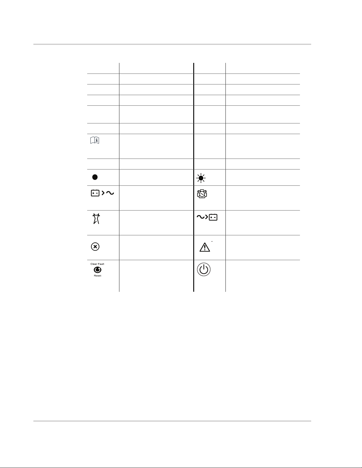
Abbreviations, Acronyms, and Symbols
AC Alternating Current LED Light Emitting Diode
AGS Automatic Generator Start SCP System Control Panel
BOS Balance of System SW Sine Wave
DC Direct Current VAC Volts, Alternating Current
PPE Personal Protective
Equipment
PV Photovoltaic IP20 Ingress protection rating
Reference to see guide
(or manual) for more
information
AC DC
Denotes a steady LED Denotes a flashing LED
Inv Enabled – see “Front
Panel LEDs” on page 3–4
for definition.
AC IN – see “Front Panel
LEDs” on page 3–4 for
definition
Fault – see “Front Panel
LEDs” on page 3–4 for
definition.
Clear Fault | Reset – see
“Conext SW Front and
Side Panels” on page 2–4
for definition.
.
VDC Volts, Direct Current
Ground
Gen Support – see “Front
Panel LEDs” on page 3–4
for definition.
Charging – see “Front
Panel LEDs” on page 3–4
for definition.
Warning – see “Front
Panel LEDs” on page 3–4
for definition.
Inv Enable – see “Conext
SW Front and Side
Panels” on page 2–4 for
definition.
Related Information
You can find more information about Schneider Electric as well as its products
and services at solar.schneider-electric.com.
iv 975-0638-01-01 Rev G
Important Safety Instructions
READ AND SAVE THESE INSTRUCTIONS - DO NOT DISCARD
This guide contains important safety instructions for the Conext SW Inverter/
Charger that must be followed during operation and troubleshooting. Read and
keep this Owner’s Guide for future reference.
Read these instructions carefully and look at the equipment to become familiar
with the device before trying to install, operate, service or maintain it. The
following special messages may appear throughout this bulletin or on the
equipment to warn of potential hazards or to call attention to information that
clarifies or simplifies a procedure.
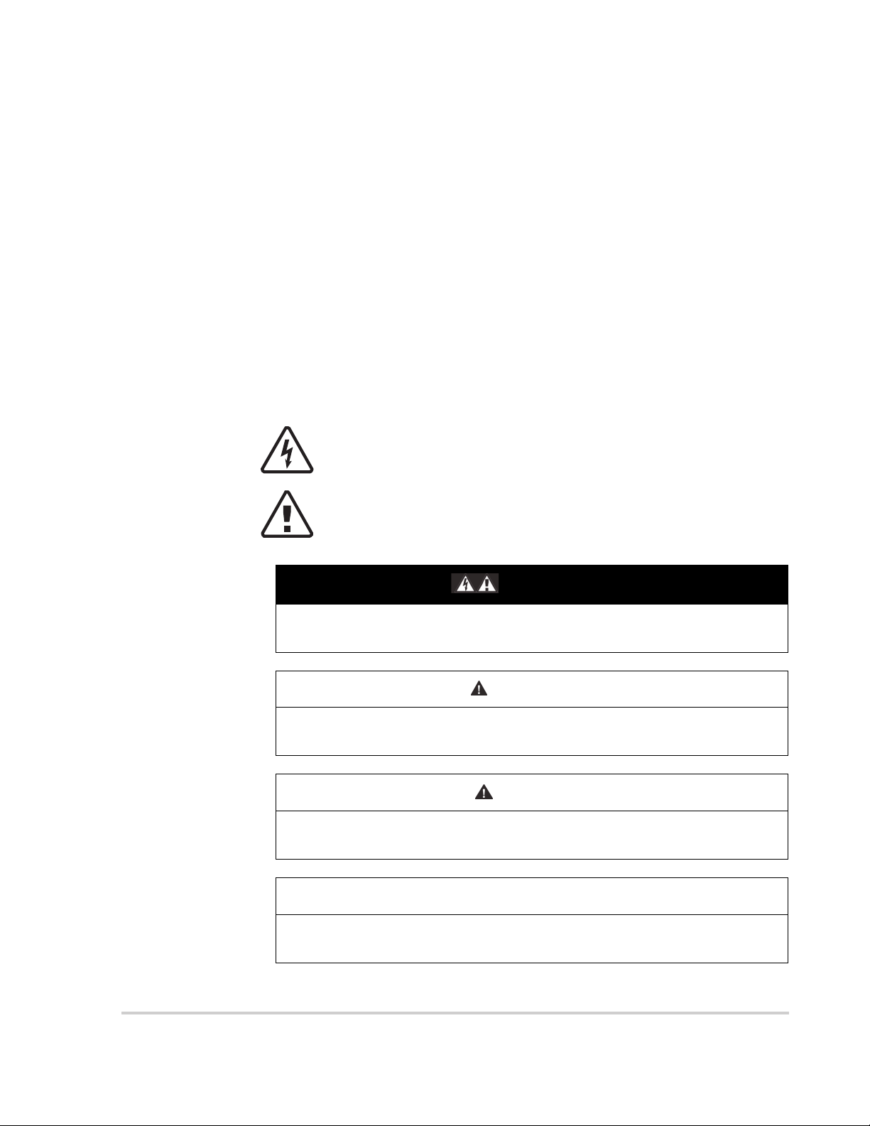
The addition of either symbol to a “Danger” or “Warning” safety label
indicates that an electrical hazard exists which will result in personal
injury if the instructions are not followed.
This is the safety alert symbol. It is used to alert you to potential
personal injury hazards. Obey all safety messages that follow this
symbol to avoid possible injury or death.
DANGER
DANGER indicates an imminently hazardous situation, which, if not avoided,
will result in death or serious injury.
WARNING
WARNING indicates a potentially hazardous situation, which, if not avoided,
can result in death or serious injury.
CAUTION
CAUTION indicates a potentially hazardous situation, which, if not avoided,
can result in moderate or minor injury.
NOTICE
NOTICE indicates a potentially hazardous situation, which, if not avoided, can
result in equipment damage.
975-0638-01-01 Rev G v
Safety
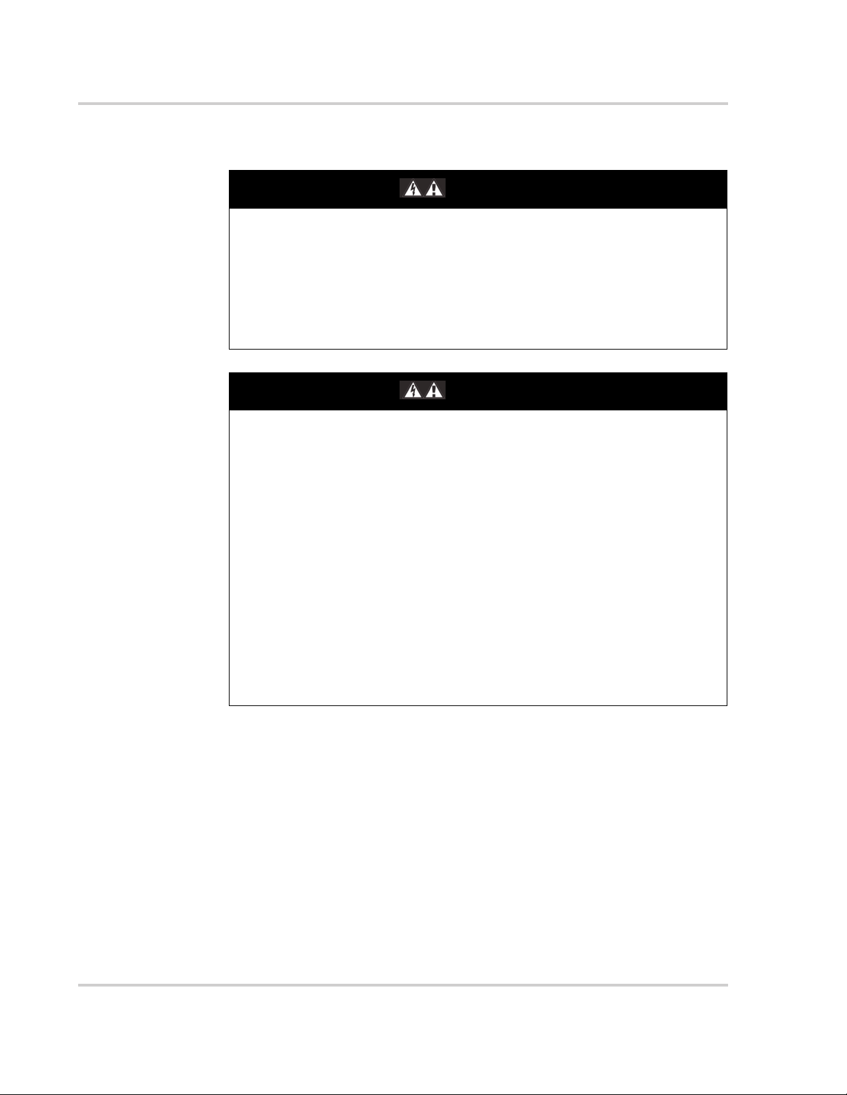
Safety Information
ELECTRICAL SHOCK AND FIRE HAZARD
Installation must be done by qualified personnel to ensure compliance with all
applicable installation and electrical codes and regulations. Instructions for
installing the Conext SW are provided in a separate installation guide for use
by qualified installers only.
Failure to follow these instructions will result in death or serious injury.
ELECTRICAL SHOCK AND FIRE HAZARD
• Read all instructions, cautionary markings, and all other appropriate
sections of this guide before operating, troubleshooting, and performing
maintenance on the Conext SW.
• Exercise extreme caution at all times to prevent accidents.
• Do not cover or obstruct ventilation openings.
• Do not mount in a zero-clearance compartment. Overheating may result.
• Do not open nor disassemble the inverter/charger. There are no userserviceable parts inside.
• Do not expose to rain or spray.
• Disconnect and lockout all AC and DC sources before servicing. Servicing
includes maintenance or cleaning or working on any circuits connected to
the inverter/charger. See following note
Failure to follow these instructions will result in death or serious injury.
DANGER
DANGER
NOTE: Turning off inverter mode using the Inv Enable switch on the front panel,
disabling the inverter and charger functions using the SCP, and putting the unit in
Standby mode will not reduce an electrical shock hazard.
vi 975-0638-01-01 Rev G
Safety
DANGER
ELECTRIC SHOCK HAZARD
• For indoor use only. This inverter/charger is designed for off-grid, solar,
backup, and hybrid applications. See the installation guide for information.
• Do not operate the inverter/charger if it has been damaged in any way.
• Do not operate the inverter/charger with damaged or substandard wiring.
Wiring must be done by qualified personnel to ensure compliance with all
applicable installation codes and regulations.
Failure to follow these instructions will result in death or serious injury.
WARNING
EXPLOSION AND FIRE HAZARD
• Charge properly rated lead-acid (GEL, AGM, Flooded, or lead-calcium)
rechargeable batteries because other battery types may explode.
• When using Lithium-Ion batteries, ensure that the battery pack being used
includes a certified Battery Management System (BMS) with safety
controls.
• Do not work in the vicinity of lead-acid batteries. Batteries generate
explosive gases during normal operation. See note #1.
• Do not install and/or operate in compartments containing flammable
materials or in locations that require ignition-protected equipment. See
notes #2 and #3.
Failure to follow these instructions can result in death or serious injury.
NOTES:
1. Follow these instructions and those published by the battery manufacturer
and the manufacturer of any equipment you intend to use in the vicinity of the
battery. Review cautionary markings on these products.
2. This inverter/charger contains components which tend to produce arcs or
sparks.
3. Locations include any space containing gasoline-powered machinery like a
generator, fuel tanks, as well as joints, fittings, or other connections between
components of the fuel system.
CAUTION
FIRE AND BURN HAZARD
Do not cover or obstruct the air intake vent openings and/or install in a zeroclearance compartment.
Failure to follow these instructions can result in moderate or minor injury.
975-0638-01-01 Rev G vii
Safety
Precautions When Working With Batteries
IMPORTANT: Battery work and maintenance must be done by qualified
personnel knowledgeable about batteries to ensure compliance with battery
handling and maintenance safety precautions.
WARNING
BURN AND FIRE HAZARD
• Always wear proper, non-absorbent gloves, complete eye protection, and
clothing protection.
• Remove all personal metal items, like rings, bracelets, and watches when
working with batteries.
• Never smoke or allow a spark or flame near batteries.
• Batteries can produce a short circuit current high enough to weld a ring or
metal bracelet or the like to the battery terminal, causing a severe burn.
Failure to follow these instructions can result in death or serious injury.
WARNING
CHEMICAL, BURN, AND EXPLOSION HAZARD
• Never place the Conext SW Inverter/Charger unit in the same compartment
as batteries due to an explosive hazard.
• Make sure the area around the battery is well ventilated.
• Make sure the voltage of the batteries matches the output voltage of the
inverter/charger.
• Never allow battery acid to drip when reading specific gravity or filling
battery.
Failure to follow these instructions can result in death or serious injury.
WARNING
LIMITATIONS ON USE
Do not use in connection with life support systems or other medical
equipment.
Failure to follow these instructions can result in death or serious injury.
LI
viii 975-0638-01-01 Rev G
Safety
NOTICE
RISK OF INVERTER/CHARGER DAMAGE
Do not exceed the maximum inverter load limit (power) on either single phase
(L1/N or L2/N). See “Inverter Specifications” on page 6–2.
Failure to follow these instructions can result in damage to equipment.
NOTICE
RISK OF INVERTER/CHARGER DAMAGE
Never place the Conext SW Inverter/Charger unit directly above batteries;
gases from a battery will corrode and damage the inverter/charger.
Failure to follow these instructions can result in damage to equipment.
NOTICE
RISK OF BATTERY DAMAGE
Study and follow all of the battery manufacturer's specific precautions, such
as removing or not removing cell caps while charging, whether equalization is
acceptable for your battery, and recommended rates of charge.
Failure to follow these instructions can result in damage to equipment.
975-0638-01-01 Rev G ix

Safety
FCC Information to the User
This equipment has been tested and found to comply with the limits for a Class B
digital device, pursuant to part 15 of the FCC Rules. These limits are designed to
provide reasonable protection against harmful interference in a residential
installation. This equipment generates, uses, and can radiate radio frequency
energy and, if not installed and used in accordance with the instructions, may
cause harmful interference to radio communications.
However, there is no guarantee that interference will not occur in a particular
installation. If this equipment does cause harmful interference to radio or
television reception, which can be determined by turning the equipment off and
on, the user is encouraged to try to correct the interference by one or more of the
following measures:
• Reorient or relocate the receiving antenna.
• Increase the separation between the equipment and receiver.
• Connect the equipment into an outlet on a circuit different from that to which
the receiver is connected.
• Consult the dealer or an experienced radio/TV technician for help.
x 975-0638-01-01 Rev G

Contents
Important Safety Instructions
Safety Information ----------------------------------------------------------vi
Precautions When Working With Batteries ----------------------------------------viii
FCC Information to the User ---------------------------------------------------x
1 Introduction
Materials List ------------------------------------------------------------1–2
Key Features ------------------------------------------------------------1–3
Key Features Explained --------------------------------------------------1–4
Basic Protection Features ---------------------------------------------------1–5
Grid-interactive and Other Features --------------------------------------------1–6
Load Shaving ---------------------------------------------------------1–6
AC Support ----------------------------------------------------------1–8
AC Support Mode using SOC ------------------------------------------1–9
Enhanced AC Support ------------------------------------------------1–9
Regular AC Support without Xanbus devices ------------------------------1–11
Grid-Interactive Delay Feature --------------------------------------------1–11
AC Coupling ---------------------------------------------------------1–12
AC Couple Smart Charge -----------------------------------------------1–13
Storing the State of the Inverter Mode --------------------------------------- 1–15
NoLoadVD ----------------------------------------------------------1–15
Low Battery Cut Out Hysteresis -------------------------------------------1–15
LBCO Delay --------------------------------------------------------- 1–15
Lithium Ion Battery Type ------------------------------------------------ 1–16
2 Components and Mechanical Features
System Components-------------------------------------------------------2–2
Xanbus System --------------------------------------------------------2–2
Xanbus-enabled Products and Other Accessories -------------------------------2–3
Conext SW Inverter/Charger Mechanical Features----------------------------------2–4
Conext SW Front and Side Panels ------------------------------------------2–4
Front Panel Buttons and Status LEDs -------------------------------------2–5
Conext SW AC/DC/Ports Side Panel --------------------------------------2–6
3 Operation
Start Up Behavior ---------------------------------------------------------3–2
Inverter Operation Using the Front Panel ----------------------------------------3–3
Operating Limits for Inverter Operation ---------------------------------------3–5
Operating Limits for Charger Operation --------------------------------------3–7
975-0638-01-01 Rev G xi

Contents
Inverter/Charger Operation using the System Control Panel (SCP) ---------------------- 3–8
SCP Features --------------------------------------------------------- 3–9
Using the Standby Button ----------------------------------------------- 3–10
SCP Navigation ------------------------------------------------------ 3–10
Startup Screen ---------------------------------------------------- 3–10
Viewing the SCP Home Screens --------------------------------------- 3–11
Viewing Other Screens ---------------------------------------------- 3–14
Changing Operational Settings ------------------------------------------- 3–16
4 Configuration via SCP
Viewing the Firmware Revision Number ----------------------------------------- 4–2
Setting the Time and Date--------------------------------------------------- 4–3
Viewing the Basic and Advanced Settings Menus---------------------------------- 4–4
Configuring Basic Settings -------------------------------------------------- 4–7
Configuring Advanced Settings----------------------------------------------- 4–9
Inverter Settings Menu -------------------------------------------------- 4–9
Using the Low Battery Cut Out and LBCO Delay Settings --------------------- 4–11
Low Battery Cut Out Hysteresis ---------------------------------------- 4–11
Using Search Mode ------------------------------------------------ 4–12
Using Inverter Block ------------------------------------------------ 4–13
Charger Settings Menu ------------------------------------------------- 4–13
Battery Charger Functions -------------------------------------------- 4–15
Multi-Stage Charging Process ----------------------------------------- 4–16
Equalize-Charging the Batteries --------------------------------------- 4–18
Using Charger Block ----------------------------------------------- 4–19
Custom Battery Settings Menu ----------------------------------------- 4–20
LithiumIon Battery Settings Menu --------------------------------------- 4–22
AC Settings --------------------------------------------------------- 4–24
AC Support Settings --------------------------------------------------- 4–25
AC Support Mode Setting -------------------------------------------- 4–27
Load Shaving Setting ----------------------------------------------- 4–29
Enhanced AC Support Setting ----------------------------------------- 4–31
Multi Unit Config Menu ------------------------------------------------- 4–32
Setting the Device Name --------------------------------------------- 4–33
Setting the Device Number ------------------------------------------- 4–34
Restoring Factory Default Settings ----------------------------------------- 4–36
Advanced Features Menu ----------------------------------------------- 4–37
EuroFreq Feature -------------------------------------------------- 4–37
xii 975-0638-01-01 Rev G

Configuration Sheet ------------------------------------------------------ 4–39
5 Troubleshooting
General Troubleshooting Guidelines -------------------------------------------5–2
Inverter Applications -------------------------------------------------------5–3
View Device Info Logs------------------------------------------------------5–4
Troubleshooting the Conext SW via the SCP --------------------------------------5–5
Fault Detection Types ---------------------------------------------------5–5
Warning Types --------------------------------------------------------5–6
6 Specifications
Inverter Specifications------------------------------------------------------6–2
Charger Specifications -----------------------------------------------------6–3
AC Transfer Specifications --------------------------------------------------6–4
Physical Specifications -----------------------------------------------------6–5
Environmental Specifications -------------------------------------------------6–5
Regulatory --------------------------------------------------------------6–6
Contents
975-0638-01-01 Rev G xiii

xiv

Figures
Figure 1-1 Materials List------------------------------------------------------1–2
Figure 1-2 Load Shaving in Action ----------------------------------------------1–7
Figure 1-3 AC Support Mode using SOC ------------------------------------------1–9
Figure 1-4 Enhanced AC Support -----------------------------------------------1–9
Figure 1-5 Enhanced AC Support Charge Cycle -----------------------------------1–10
Figure 1-6 Regular AC Support without Xanbus Devices------------------------------ 1–11
Figure 1-7 Load Shaving 2-Hour Delay Example -----------------------------------1–12
Figure 2-1 Xanbus System Components ------------------------------------------2–2
Figure 2-2 Conext SW Front and Side Panels---------------------------------------2–4
Figure 2-3 Front Panel Buttons and Status LEDs ------------------------------------2–5
Figure 2-4 AC and DC Terminals, Network and Communication Ports Panel-----------------2–6
Figure 3-1 Startup Screen --------------------------------------------------- 3–10
Figure 3-2 SCP Top Level Screens --------------------------------------------- 3–11
Figure 3-3 System Status Screen ----------------------------------------------3–12
Figure 3-4 Conext SW Home Screen --------------------------------------------3–12
Figure 3-5 Selecting a Device Setup Menu ---------------------------------------3–14
Figure 3-6 Viewing the Meters Screen -------------------------------------------3–15
Figure 3-7 Navigate To Conext SW Setup Menu------------------------------------ 3–16
Figure 3-8 Conext SW Setup Menu Operational Settings------------------------------ 3–18
Figure 4-1 Selecting Basic Settings---------------------------------------------- 4–4
Figure 4-2 Selecting Advanced Settings ------------------------------------------4–6
Figure 4-3 Menu Map of the Conext SW Basic Settings--------------------------------4–7
Figure 4-4 Inverter Settings Menu Screen -----------------------------------------4–9
Figure 4-5 Charger Settings Menu Screen ----------------------------------------4–13
Figure 4-6 Custom Settings Menu Screen ----------------------------------------4–20
Figure 4-7 LithiumIon Settings Menu Screen -------------------------------------- 4–22
Figure 4-8 AC Settings Menu Screen--------------------------------------------4–24
Figure 4-9 AC Support Menu Screen-------------------------------------------- 4–25
Figure 4-10 Multi Unit Config Menu Screen ----------------------------------------4–32
Figure 4-11 Setting a Device Number -------------------------------------------- 4–35
Figure 4-12 Adv Features Menu Screen ------------------------------------------4–37
Figure 5-1 View Device Info Log ------------------------------------------------5–4
Figure 6-1 Output Power versus Temperature Derating Graph --------------------------6–5
975-0638-01-01 Rev G xv

xvi

Tables
Table 3-1 Front Panel LEDs---------------------------------------------------3–4
Table 3-2 Conext SW Home Screen States ---------------------------------------3–13
Table 3-3 Meters Screen---------------------------------------------------- 3–15
Table 3-4 Conext SW Setup menu ---------------------------------------------3–17
Table 4-1 Setting Defaults and Ranges ------------------------------------------4–7
Table 4-2 Basic Settings -----------------------------------------------------4–8
Table 4-3 Setting Defaults and Ranges ------------------------------------------4–9
Table 4-4 Inverter Settings Description------------------------------------------ 4–10
Table 4-5 Setting Defaults and Ranges ----------------------------------------- 4–14
Table 4-6 Charger Settings Menu Description------------------------------------- 4–14
Table 4-7 Bulk Voltage Settings for Different Battery Types --------------------------- 4–16
Table 4-8 Preset Absorption Voltage Settings for Different Battery Types -----------------4–16
Table 4-9 Preset Float Voltage Settings for Different Battery Types ----------------------4–17
Table 4-10 Preset Equalization Voltage Settings for Different Battery Types ----------------4–18
Table 4-11 Setting Defaults and Ranges -----------------------------------------4–20
Table 4-12 Custom Battery Settings Menu Description ------------------------------- 4–21
Table 4-13 Setting Defaults and Ranges -----------------------------------------4–22
Table 4-14 LithiumIon Battery Settings Menu Description -----------------------------4–23
Table 4-15 Setting Defaults and Ranges -----------------------------------------4–24
Table 4-16 AC Settings menu ------------------------------------------------- 4–24
Table 4-17 AC Support Menu Description and Values --------------------------------4–25
Table 4-18 Multi Unit Menu Description and Values---------------------------------- 4–32
Table 4-19 Adv Features Description and Values ----------------------------------- 4–37
Table 5-1 Fault Detection Types and Behaviors ------------------------------------5–5
Table 5-2 Warning Types and Behavior ------------------------------------------5–6
Table 5-3 Fault Detection Messages --------------------------------------------5–7
Table 5-4 Warning Messages ------------------------------------------------5–12
975-0638-01-01 Rev G xvii

xviii

1 Introduction
The following topics will be covered in this
chapter.
• Material List
• Key Features
• Basic Protection Features
• Grid-interactive and Other Features
975-0638-01-01 Rev G 1–1
Introduction
Materials List
Congratulations on your purchase of the Conext SW Inverter/Charger (called
Conext SW). The Conext SW has been designed to give you premium true sine
wave power, ease of use, and outstanding reliability for your off-grid and power
backup applications.
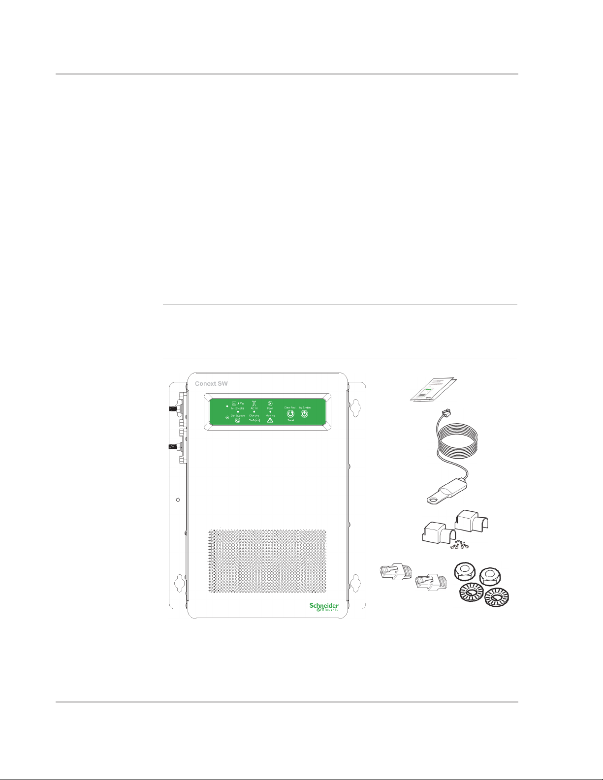
The Conext SW ships with the following items:
• One Conext SW unit
• One set of owner’s and installation guides
• One Battery Temperature Sensor (BTS)
• Two Xanbus network terminators
• Two sets of 5/16
• Two DC terminal covers (red and black) with two sets of #6-32 screws
• One Installation bracket with one set of M6 nuts for mounting (not shown)
NOTE: If any of the supplied accessories are missing, contact customer
service for replacement. For code-compliant installations in Canada and USA,
the DC Switch Gear accessory is required. See the Installation Guide for more
information.
"-18
nuts and washers for the DC terminals,
Figure 1-1 Materials List
1–2 975-0638-01-01 Rev G

Key Features
Key Features
The Conext SW Inverter/Charger is a true sine wave inverter/charger that can be
used for off-grid, backup, solar, and hybrid applications. The Conext SW Inverter/
Chargers are designed to operate with a wide variety of generators and are
capable of operating in parallel with a generator for short durations to assist with
starting large loads. The Conext SW is a convenient combination of an inverter,
multi-stage battery charger, and transfer switch in one electronic device.
The Conext SW Inverter/Charger’s key features are:
True Sine Wave output
•
power for your microwave, entertainment system, computer, and other loads.
This power is identical to the AC source provided from the utility grid (power
company).
Some of the benefits of high efficiency true sine wave power include consistent
cooking in your microwave, handling of sensitive loads such as your TV set,
dimmer switches, and appliances with speed controls.
•
Multiple unit configuration
versatile platform capable of parallel multiple unit configuration1to increase
power levels.
•
High surge capacity
twice the maximum continuous output power rating to start difficult loads like well
pumps, refrigerators, or A/C compressors. See “Inverter Specifications” on
page 6–2.
•
Power factor correction
input current required for charging, increasing AC pass-through capacity.
•
Multi-stage charging
stage charging capability that minimizes charging time.
•
Adjustable frequency
from a 50Hz and 60Hz power source by extending the AC qualification frequency
range. See “AC Settings” on page 4–24.
•
Temperature-controlled, variable-speed internal cooling fans
on when the internal temperature reaches
speed at
104 °F (
•
Xanbus-enabled
which allows network compatibility and communication with other Xanbusenabled devices. See more information under “Xanbus System” on page 2–2.
158 °F (
40 °C).
70 °C). The fan turns off when the internal temperature falls to
- as an inverter, the Conext SW provides true sine wave
- the Conext SW Inverter/Charger has a highly
- the Conext SW Inverter/Charger has a surge rating that is
- Power factor-corrected (PFC) input minimizes AC
- the Conext SW Inverter/Charger has a high output, multi-
- the Conext SW Inverter/Charger is capable of operating
- the fans turn
113 °F (
- the Conext SW Inverter/Charger is also Xanbus-enabled
45 °C) and reaches maximum
1.In Conext SW Inverter/Chargers, multiple unit configuration (installation) is limited to two
units - one master unit and one slave unit.
975-0638-01-01 Rev G 1–3

Introduction
Key Features Explained
Built-in Charge
Formulas
Battery
Temperature
Sensor
Dead Battery
Charging
Manual
Equalization
Load Management The Conext SW has a built-in transfer relay that connects your inverter output or
1
For the unit to perform at the highest level, the batteries must be charged
correctly. The Conext SW has optimized algorithms for flooded, gel, and AGM
batteries.
Since battery temperature is a key factor in correct charging, the charging
formula must be adjusted (automatically and in real time) according to the actual
battery temperature to ensure that batteries are fully charged, but not
overcharged. For this reason, a battery temperature sensor (BTS) is included
with the Conext SW that works with a temperature-compensated charge formula.
Another feature that the Conext SW includes is dead battery charging. The
Conext SW—unlike many chargers—has the ability to recharge batteries even if
the battery voltage is very low, that is, as low as 12 volts.
Over a period of time, the cells in a flooded battery can develop uneven
chemical states. This can result in a weak (undercharged) cell which, in turn, can
reduce the overall capacity of the battery. To improve the life and performance of
a non-sealed, flooded battery, the Conext SW’s multi-stage charging cycle
includes a manual equalize mode that can be used, if recommended by the
battery manufacturer.
AC input from the AC generator to your loads. Because the usual AC power
sources such as small generators often have limited current availability, having
the capability to manage your AC loads is extremely valuable. The Conext SW
provides a number of features to facilitate this.
• The charger is power factor corrected to use AC current as efficiently as
possible. Minimizing the AC current used by the charger means more
current is available for your AC loads.
• The Conext SW has a power share feature which prioritizes your AC
loads by reducing the charge current depending on the load current;
and programmed AC breaker setting.
Occasionally, AC input sources have low voltage. To avoid loading these weak
sources any further, the charger automatically reduces its AC current draw as the
AC voltage approaches the minimum acceptable level.
Multiple Unit
Configuration
1.Requires a 240V AC input. The feature does not work on 120V AC input only.
Conext SW Inverter/Charger supports multiple unit configuration to increase
capacity. Conext SW multiple unit configuration is limited to one master unit and
one slave unit.
Multiple Unit Inverting
Multiple unit configuration allows two inverter/chargers to operate in parallel
thereby doubling the capacity in inverter mode. The multiple inverters
communicate over the Xanbus network and intelligently manage the load
balance between the units.
1–4 975-0638-01-01 Rev G

Multiple Unit Charging
Two Conext SW Inverter/Chargers synchronize charging stages to ensure
efficient charging of the battery bank. When a single unit transitions from bulk to
absorption so does the other unit. In absorption, the two units must complete the
absorption stage before transitioning to the next stage. Note that the two units do
not load share when charging except during the bulk stage. The Conext SW units
stop sharing charge current just before completing the bulk stage. The units do
not share charge current during the absorption and float stages.
Each unit charges batteries based on the Max Charge Rate setting and active
internal (temperature-based) deratings.
If equalization is enabled on one or more devices capable of equalization
charging, only those devices perform an equalize cycle after absorption. Other
devices transition to float (if three-stage charging is selected) or transition to AC
pass-through (if two-stage charging is selected).
Basic Protection Features
The Conext SW has the following protection features:
• Over temperature shutdown for critical components such as the transformer
and the power board
• Battery temperature sensor (BTS) failure/battery temperature out-of-range
fault protection
• DC output over voltage protection during charge mode
• AC output overload and short circuit protection during invert mode
Basic Protection Features
• AC backfeed1protection
The Battery Temperature Sensor (BTS) provides these protection features:
• battery over temperature charging protection preventing battery charging at
140 °F (60 °C) or higher, and
• charging voltage compensation based on the temperature of the battery the
BTS is connected to.
1.An AC backfeed error occurs when the AC output of the inverter/charger is connected or
routed back to the inverter/charger’sAC input terminalor ifthe ACinternal transferrelay error is
detected.
975-0638-01-01 Rev G 1–5

Introduction
Grid-interactive and Other Features
Load Shaving
Load shaving (Load Shave) allows the Conext SW to support (or assist) the AC
source in powering local loads during a defined window of time (LoadShaveStart
and LoadShaveStop). See “Time-of-Use Metering” on page 1–7. It allows the
inverter to control how much current can be drawn from the AC source.
The Conext SW transitions to load shaving mode only when both the phase
currents exceed Load Shave Amps. It uses battery power to limit the peak load on
the AC input by providing the difference in amps between the actual load current
and the current limit set in Load Shave Amps. Some scenarios are presented
below to reflect this behavior.
Scenario 1
Load Shave Amps = 5A,
L1 = 7A of AC load,
L2 = 3A of AC load
Conext SW will not enter into the AC load shaving mode because one of the
phase currents (L1 or L2) is lower than the value of Load Shave Amps.
(L2 =3A) < (Load Shave Amps = 5A)
Scenario 2
Load Shave Amps = 5A,
L1 = 7A of AC load,
L2 = 9A of AC load
In this scenario, the Conext SW enters into the AC load shaving mode because
both phase currents exceed the value of Load Shave Amps.
(L1 =7A) > (Load Shave Amps = 5A)
The difference between these two values is 2A.
Conext SW will shave off 2A from each phase, meaning, the current draw from L1
will be limited to 5A and L2 limited to 7A.
However, when the battery is in charge mode, the total AC input current is limited
by 80% of Load Shave Amps to avoid the fluctuation between battery charge and
discharge.
This fluctuation is described as follows:
• If the AC input current limit is the same value as Load Shave Amps in battery
charge mode, the charge current can be higher than the limit value due to
the charge dynamics. Under this condition, the battery will enter into
discharge mode because the AC current is higher than Load Shave Amps.
After the battery is in discharge mode, the battery will go back into charge
mode again because the load current is smaller than Load Shave Amps.
1–6 975-0638-01-01 Rev G

Grid-interactive and Other Features
• Therefore, the battery will fluctuate between the charge and discharge
modes. In order to avoid this fluctuation, a hysteresis band is set by limiting
the AC input current to 80% of Load Shave Amps when the battery is in the
charge mode.
In a grid-interactive backup system Load shaving combined with time-of-use
metering helps reduce utility peak demand surcharges.
In an off-grid system with generator Load shaving can be used to support the
generator. If the generator is unable to provide enough current to run loads in the
system, load shaving ensures that the system does not exceed the generator’s
current rating. This is done by matching the generator’s manufacturer
recommended current rating with the Load Shave Amps setting.
See “Load Shaving Setting” on page 4–29 for a sample scenario.
NOTE: Current is regulated by placing a limit (Load Shave Amps) on the current
of the AC source.
15 A10 A
5A
Figure 1-2 Load Shaving in Action
Time-of-Use Metering Utilities use time-of-use metering to set utility charges
during peak usage hours and to impose a surcharge. The Conext SW can be
configured (using the LoadShaveStart, LoadShaveStop and charger block [see
the Conext SW Owner’s Guide] settings) to overcome these peak charges by
using utility power to charge the battery bank during the inexpensive energy
hours and consuming the battery energy during expensive energy hours.
For example, if charger block is set between 9:00 AM and 10:00 PM and load
shaving is set between LoadShaveStart=6:00 PM and LoadShaveStop=9:00 PM,
charging on AC Input stops at 9:00 AM and the inverter continues to pass utility
AC through to the loads. If charging is required during the charger block period
then Conext SW can use an alternative external renewable energy source such
as an MPPT solar charge controller to charge the battery bank. The inverter
connects to the utility grid at 6:00 PM and supports running the loads using the
batteries. The inverter continues to run the loads until 9:00 PM.
The Conext SW then stops supporting the utility grid and passes utility AC
through to the loads at 9:01 PM. At the end of charger block at 10:00 PM utility
AC begins maintaining the batteries based on charger settings.
The above example allows an external renewable energy source to be utilized as
a primary charging source during a desired time window. The charger (using
utility power connected to AC Input) can then be used to supplement battery
charging when the utility rates are low.
975-0638-01-01 Rev G 1–7

Introduction
AC Support
When using the system for time-of-use metering, the system should be designed
with a battery capacity large enough to support loads during the entire peak rate
period without reaching the low battery cut out (Low Batt Cut Out) setting.
Load shaving can also be used with time-of-use metering and enhanced AC
support feature (see “Enhanced AC Support” on page 1–9 and “Enhanced AC
Support Setting” on page 4–31) to support self-consumption.
AC Support is similar to load shaving because in both cases the Conext SW
inverter supplements AC current. However, unlike load shaving, AC Support
minimizes the AC input current to the Conext SW as long as the battery’s SOC
(state-of-charge) or battery voltage conditions allow it. AC Support allows the
Conext SW to support local loads by converting excess power from external DC
sources connected to its battery bank. Examples of external DC sources are
MPPT solar charge controllers. When local loads demand more energy from the
external DC sources then extra current can be pulled in from the AC source as a
last resort. When operating without a solar charge controller in the system, set
the battery charge cycle to 2StgNoFloat to allow AC Support to function
immediately after the absorption charge stage.
When Conext SW is operating in AC support mode, it only compensates AC
loads which are connected to both phases and having equal power. The
difference in power between the two phases will be drawn from the AC source.
Some scenarios are presented below to reflect this behavior.
Scenario 1
L1 = 3A of AC load,
L2 = 3A of AC load
In this scenario, the Conext SW injects 3A into each phase to offset both loads.
Scenario 2
L1 = 5A of AC load,
L2 = 3A of AC load
In this second scenario where power from the two loads is unequal, the Conext
SW still injects 3A (the lesser of the two AC loads) into each phase. However, the
difference of 2A on L1 shall be drawn from the grid.
AC Support behaves three different ways depending on the type of equipment
that is installed in the Xanbus network with the Conext SW.
• SOC - Xanbus-enabled Conext Battery Monitor is installed
• Enhanced - Xanbus-enabled MPPT solar charge controller is installed
• Regular - neither Xanbus-enabled battery monitor nor MPPT solar charge
controller is installed
1–8 975-0638-01-01 Rev G
AC Support Mode using SOC
With AC support on SOC (AC Supp on SOC) enabled (default setting), Conext SW
maximizes power utilization using stored energy in a battery bank within a gridinteractive backup power system. AC support mode allows the Conext SW to
accurately determine when grid power can be used to supply energy to the
loads by knowing the state-of-charge (SOC) of the battery bank.
The SOC of a battery bank is monitored by using a Xanbus-enabled battery
monitor. SOC entry and exit points are determined by the user. The SOC entry
point (AC Supp Start Soc) which is a high percentage value determines when
AC support mode is engaged and the SOC exit point (AC Supp Stop Soc) which
is a low percentage value determines when AC support mode is disengaged.
See “AC Support Settings” on page 4–25.
Grid-interactive and Other Features
15 A<2A*
>13A
NOTE: Entry and exit into AC Support
Mode is determined by the SOC. In this
case, AC support mode is engaged.
Figure 1-3 AC Support Mode using SOC
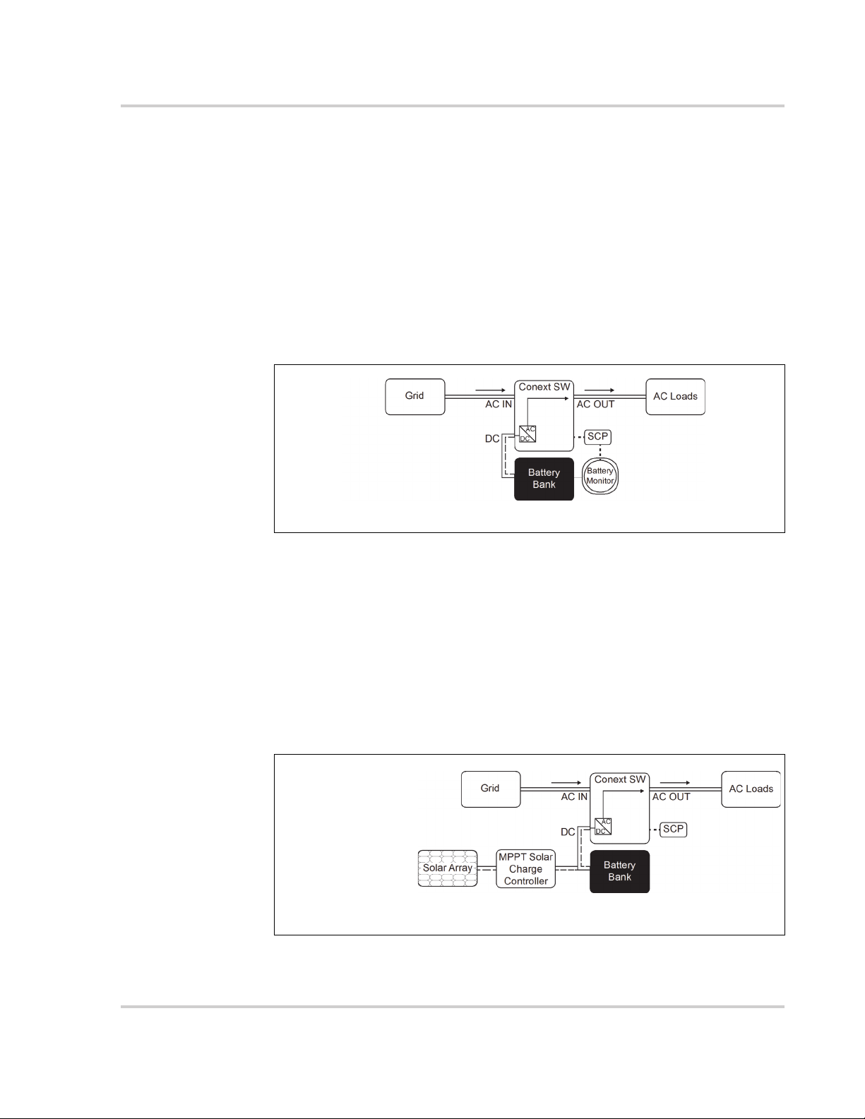
Enhanced AC Support
Enhanced AC Support (EnhancedACSup) works when power systems are DC
coupled with a Xanbus-enabled MPPT Solar Charge Controller. This means that
DC power from a renewable source such as an MPPT Solar Charge Controller is
used to charge the battery bank while simultaneously utilizing its power (by way
of inverting) to power loads. Entry and exit to enhanced AC support are
controlled by the MPPT charger so that they can control the state-of-charge of
the batteries. AC power from the grid is utilized only when load demand exceeds
power available from the MPPT charger for charging and supplying the loads.
NOTE: Entry and exit into
Enhanced AC Support is
determined by the MPPT.
SOC Entry = 80%
actual SOC = 75%
SOC Exit = 50%
* To prevent injecting current into the grid from the inverter, there is less than 2 amps of offset allowed
from the grid to flow into AC IN under all conditions.
15 A<2A*
>13A
* To prevent injecting current into the grid from the inverter, there is less than 2 amps of offset allowed
from the grid to flow into AC IN under all conditions.
Figure 1-4 Enhanced AC Support
975-0638-01-01 Rev G 1–9
Introduction
When enhanced AC support mode is enabled, the Conext SW automatically
tracks the MPPT solar charge controller’s charging voltage as it transitions from
bulk to absorption to float. By tracking the voltage, the Conext SW is then able to
execute and finish the charging cycle using DC power from the solar charge
controller while converting its excess DC power to AC power to support the grid
by supplying more current. Conext SW only uses excess DC power not required
by the battery to support the grid thus, it prioritizes charging the battery before
supporting the loads. Battery health is improved because the system always
executes a three stage charging of the battery that ensures battery SOC is as
close as possible to 100% at all times. Systems that use a fixed voltage for AC
support (or similar) start to support loads sooner and may not fully charge the
battery bank, leaving the battery in a partial SOC. Prolonged periods of partial
SOC can degrade battery performance. Enhanced AC support limits this
degrading effect.
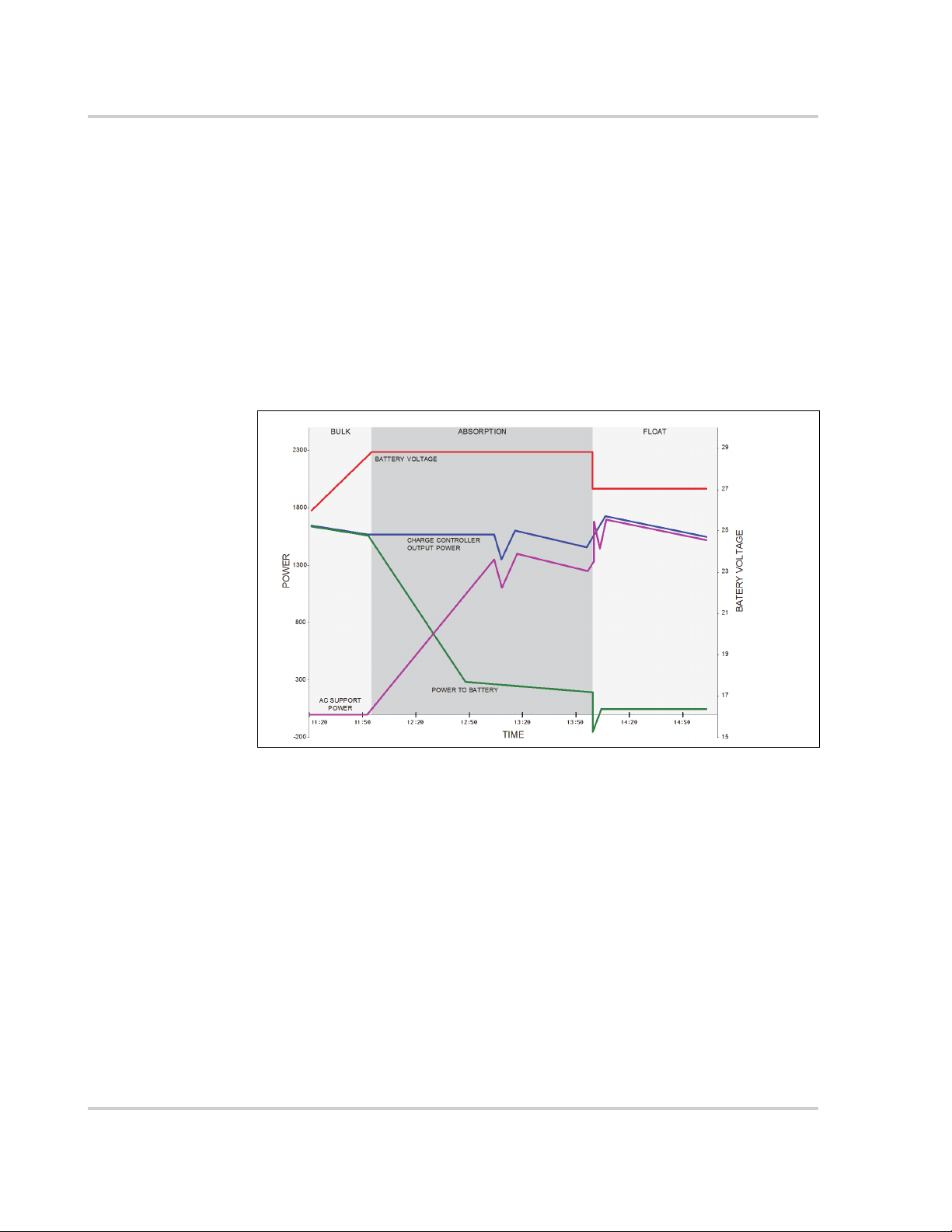
Figure 1-5 Enhanced AC Support Charge Cycle
Enhanced AC Support Charging Stages
• BULK Phase - During this phase, all PV energy from the charge controller is
diverted to the battery for maximum charging. During this phase, the Conext
SW does not engage AC support.
• ABSORPTION Phase - Once the charge controller is in absorption phase,
the charge controller output is split between the battery and Conext SW for
supporting AC loads. As the battery approaches full charge, more power
from the charge controller is diverted to Conext SW for AC support.
• FLOAT Phase - Once the battery is full and the charge controller transitions
to float phase, almost all the charge controller output is used by Conext SW
to support AC loads. The battery only receives a trickle charge to maintain a
healthy state of charge.
See “Enhanced AC Support Setting” on page 4–31.
1–10 975-0638-01-01 Rev G
 Loading...