


Schneider Electric T300 User Manual

MV Network Management
Easergy
T300
Remote Terminal Unit for distribution networks
User Manual

Safety information
Hazard Categories and Special Symbols
Read these instructions carefully and look at the equipment to become familiar with
the device before trying to install, operate, service or maintain it. The following
special messages may appear throughout this bulletin or on the equipment to warn
of potential hazards or to call attention to information that clarifies or simplifies a
procedure.
The addition of either symbol to a “Danger” or “Warning” safety label indicates
that an electrical hazard exists which will result in personal injury if the
instructions are not followed.
This is the safety alert symbol. It is used to alert you to potential personal
injury hazards. Obey all safety messages that follow this symbol to avoid
possible injury or death.
DANGER
DANGER indicates a hazardous situation which, if not avoided,
will result in death or serious injury.
WARNING
WARNING indicates a hazardous situation which, if not avoided,
could result in death or serious injury.
CAUTION
CAUTION indicates a hazardous situation which, if not avoided,
could result in minor or moderate injury.
NOTICE
NOTICE is used to address practices not related to physical injury. The safety alert symbol
shall not be used with this signal word.
Please Note
Electrical equipment should be installed, operated, serviced, and maintained only by
qualified personnel. No responsibility is assumed by Schneider Electric for any
consequences arising out of the use of this material.
A qualified person is one who has skills and knowledge related to the construction,
installation, and operation of electrical equipment and has received safety training to
recognize and avoid the hazards involved.
2
NT00378-EN-03

Safety information
Legal information
The Schneider Electric brand and any registered trademarks of Schneider Electric
Industries SAS referred to in this guide are the sole property of Schneider Electric SA and
its subsidiaries. They may not be used for any purpose without the owner's permission,
given in writing. This guide and its content are protected, within the meaning of the French
intellectual property code (Code de la propriété intellectuelle français, referred to hereafter
as "the Code"), under the laws of copyright covering texts, drawings and models, as well
as by trademark law. You agree not to reproduce, other than for your own personal,
noncommercial use as defined in the Code, all or part of this guide on any medium
whatsoever without Schneider Electric’s permission, given in writing. You also agree not
to establish any hypertext links to this guide or its content.
Schneider Electric does not grant any right or license for the personal and noncommercial
use of the guide or its content, except for a non-exclusive license to consult it on an "as is"
basis, at your own risk. All other rights are reserved.
As standards, specifications and designs change from time to time, please ask for
confirmation of the information given in this publication.
FCC Part 15
This equipment has been tested and found to comply with the limits for a Class B digital
device, pursuant to part 15 of the FCC Rules. These limits are designed to provide
reasonable protection against harmful interference in a residential installation. This
equipment generates, uses and can radiate radio frequency energy and, if not installed
and used in accordance with the instruction, may cause harmful interference to radio
communications. However, there is no guarantee that interference will not occur in a
particular installation. If this equipment does cause harmful interference to radio or
television reception which can be determined by turning the equipment off and on, the
user is encouraged to try to correct interference by one or more of the following
measures:
- Reorient or relocate the receiving antenna.
- Increase the separation between the equipment and receiver.
- Connect the equipment into an outlet on circuit different from that to which the
- Consult the dealer or an experienced radio/TV technician for help.
This device complies with FCC RF radiation exposure limits set forth for general
population. This device must be installed to provide a separation distance of at least 20cm
from all persons and must not be co-located or operating in conjunction with any other
antenna or transmitter.
receiver is connected.
NT00378-EN-03
3

Easergy T300 Contents
1
GENERAL DESCRIPTION ................................................................................................................................. 6
1.1 FUNCTIONAL DESCRIPTION .................................................................................................................................... 6
1.2 DESCRIPTION OF T300 MODULES .......................................................................................................................... 7
1.2.1 HU250 Module – CPU and Communication Gateway ............................................................................. 7
1.2.2 SC150 Module – Switch Control Unit ...................................................................................................... 7
1.2.3 LV150 Module – Low Voltage measuring Unit ......................................................................................... 8
1.2.4 PS50 Module – Backup Power Supply for severe environments ............................................................ 8
1.2.5 PS25 Module – Backup Power Supply for monitoring and control solutions ........................................... 8
1.3 T300 INTERNAL ARCHITECTURE ............................................................................................................................ 9
1.4 T300 CONFIGURATION PRINCIPLE ....................................................................................................................... 10
1.4.1 Engineering in Easergy Builder ............................................................................................................. 10
1.4.2 Management of RBAC and security policy ............................................................................................ 12
1.5 INITIAL START-UP ............................................................................................................................................... 13
2 CONNECTING TO THE T300 WEB SERVER .................................................................................................. 14
3 OVERVIEW OF THE T300 WEB SERVER ...................................................................................................... 15
3.1 DATA CONSULTATION AND MONITORING PAGES ................................................................................................... 17
3.1.1 Home Page ............................................................................................................................................ 17
3.1.2 Substation Page ..................................................................................................................................... 18
3.1.3 System Page .......................................................................................................................................... 24
3.1.4 Data Pages ............................................................................................................................................ 26
3.2 MEASUREMENTS ................................................................................................................................................. 29
3.2.1 Measurements Pages ............................................................................................................................ 29
3.3 DIAGNOSTIC FILES .............................................................................................................................................. 33
3.3.1 Events Page ........................................................................................................................................... 33
3.3.2 System Page .......................................................................................................................................... 34
3.3.3 Cyber-Security Page .............................................................................................................................. 34
3.4 TRACES .............................................................................................................................................................. 35
3.4.1 Protocol Traces ...................................................................................................................................... 35
3.5 SYSTEM CYBER-SECURITY .................................................................................................................................. 36
3.5.1 Users and roles ...................................................................................................................................... 36
3.5.2 Centralized authentication with RADIUS ............................................................................................... 40
3.6 DEVICE SYNCHRONIZATION ................................................................................................................................. 45
3.6.1 Clock Page ............................................................................................................................................. 45
3.7 IP INTERFACES ................................................................................................................................................... 46
3.7.1 IP Configuration Page ............................................................................................................................ 46
3.8 DIAL-UP MODEM SETTINGS ................................................................................................................................. 51
3.8.1 Modems Configuration Page ................................................................................................................. 51
3.9 UPGRADING THE FIRMWARE ................................................................................................................................ 53
3.9.1 Firmware Page ....................................................................................................................................... 53
3.10 MANAGING THE CONFIGURATION .................................................................................................................... 55
3.10.1 Configuration Page ................................................................................................................................ 55
4 T300 SETTINGS ............................................................................................................................................... 59
4.1 HU250 MODULE SETTINGS ................................................................................................................................. 60
4.1.1 Local I/O ................................................................................................................................................. 60
4.1.2 SCADA Protocols ................................................................................................................................... 64
4.1.3 Master Protocols .................................................................................................................................... 64
4.1.4 Configuring the Physical Ports ............................................................................................................... 65
4.1.5 Synchronization ..................................................................................................................................... 69
4.2 SC150 MODULE SETTINGS ................................................................................................................................. 71
4.2.1 MV Current and Voltage Sensors .......................................................................................................... 72
4.2.2 Switch Control ........................................................................................................................................ 76
4.2.3 Front panel voltage indication ................................................................................................................ 84
4.2.4 MV Voltage Monitoring ........................................................................................................................... 85
4.2.5 Fault current Detection ........................................................................................................................... 88
4.2.6 Fault Current validation and indication ................................................................................................ 104
4.2.7 MV Power Measurement Settings ....................................................................................................... 110
4.2.8 MV Power Quality Settings .................................................................................................................. 111
4.2.9 Automation Settings ............................................................................................................................. 112
4
NT00378-EN-03

Easergy T300 Contents
4.3
LV150 MODULE SETTINGS ................................................................................................................................ 114
4.3.1 LV Current and Voltage Sensors ......................................................................................................... 115
4.3.2 Front panel voltage indication .............................................................................................................. 118
4.3.3 LV Voltage Monitoring .......................................................................................................................... 119
4.3.4 Broken Phase Conductor Detection .................................................................................................... 122
4.3.5 LV Power Measurement Settings ........................................................................................................ 124
4.3.6 Power Quality Settings ......................................................................................................................... 125
4.4 PS50 MODULE SETTINGS ................................................................................................................................. 126
4.5 COMMISSIONING TESTS .................................................................................................................................... 127
5 OPERATION ................................................................................................................................................... 128
5.1 INDICATIONS AND ACTIONS ON THE FRONT PANEL ................................................................................................... 128
5.2 TESTING THE LEDS ON THE FRONT PANEL ......................................................................................................... 134
5.3 LOCAL/REMOTE MODE ...................................................................................................................................... 134
5.3.1 Automation Enabled ............................................................................................................................. 135
5.4 SWITCH COMMANDS ......................................................................................................................................... 135
5.5 OTHER COMMANDS .......................................................................................................................................... 135
5.6 BLMON UTILITY ................................................................................................................................................ 136
5.6.1 Accessing BLMon ............................................................................................................... ................. 136
5.6.2 Using BLMon........................................................................................................................................ 137
6 MAINTENANCE .............................................................................................................................................. 138
6.1 DIAGNOSTIC LEDS ON THE FRONT PANEL .......................................................................................................... 139
6.2 POWERING DOWN THE EQUIPMENT .................................................................................................................... 143
6.3 BATTERY MAINTENANCE ................................................................................................................................... 143
6.3.1 Replacing the Battery ........................................................................................................................... 143
6.3.2 Battery Care and Storage .................................................................................................................... 143
6.4 REPLACING THE HU250, SC150 OR LV150 MODULE ......................................................................................... 144
6.4.1 Addressing the SC150 and LV150 Modules ........................................................................................ 144
6.4.2 Checking the Firmware Version ........................................................................................................... 144
6.4.3 Importing a Stored Configuration ......................................................................................................... 144
6.5 REPLACING A BOX MODEM ................................................................................................................................ 145
6.6 REPLACING THE PS50 MODULE ........................................................................................................................ 145
6.6.1 Addressing the PS50 Module .............................................................................................................. 145
6.6.2 Commissioning .................................................................................................................................... 145
6.7 REPLACING THE PS25 MODULE ........................................................................................................................ 145
7 APPENDIX A - GENERAL CHARACTERISTICS .......................................................................................... 146
7.1 HU250 ............................................................................................................................................................ 146
7.2 SC150 ............................................................................................................................................................. 147
7.3 LV150 ............................................................................................................................................................. 148
7.4 HU250, SC150 AND LV150 ............................................................................................................................. 149
7.5 PS50 ............................................................................................................................................................... 150
7.6 PS25 ............................................................................................................................................................... 152
8 ANNEXE B: LIST OF POTENTIAL ISSUE CODES ....................................................................................... 153
8.1 SC150 POTENTIAL ISSUE CODES ON SWITCH CONTROL ....................................................................................... 153
9 APPENDIX C: GLOSSARY ............................................................................................................................ 154
9.1 ABBREVIATIONS AND DEFINITIONS ..................................................................................................................... 154
10 APPENDIX D: INVERSE DEFINITE MINIMUM TIME (IDMT) CURVES ........................................................ 157
NT00378-EN-03
5

Presentation General description
DANGER
HAZARD OF ELECTRIC SHOCK, EXPLOSION, OR
ARC FL ASH
Wear your personal protective equipment (PPE) and
comply with the safe electrical work practices. See
NFPA 70E in the USA or applicable local standards.
This unit must be installed and serviced only by
qualified electrical personnel.
Turn off all power supplying this unit before working
on or inside the unit.
Always use a properly rated voltage sensing device to
confirm that the power is off.
A live current transformer secondary circuit must not
be opened without turning off the primary side of the
transformer and short-circuiting transformer secondary
circuit first.
Replace all devices, doors and covers before turning
on power to this unit.
Failure to follow these instructions will result in
death or serious injury.
WARNING
LOSS OF CONTROL
The designer of any control scheme must consider the
potential failure modes of control paths and, for certain
critical control functions, provide a means to achieve a
safe state during and after a path failure. Example:
Emergency Stop.
Separate or redundant control paths must be provided
for critical control functions.
System control paths may include communication
links. Consideration must be given to the implications
of anticipated transmission delays or failures of the
link.
Failure to follow these instructions can result in
death or serious injury.
1 General description
1.1 Functional description
Easergy T300 features a modular architecture designed for applications in MV
network substations.
The T300 offers the following functions:
Management of the open/close motor mechanism on MV switchgear,
compatible with any MV switch
Detection of ammetric and directional fault currents on the MV
network: operational on any neutral system with or without the presence of
distributed power and including fault current algorithms based on the
following international standards:
o Phase overcurrent and ground fault detection (ANSI 50/51,
ANSI 50N/51N)
o Directional overcurrent and ground fault detection (ANSI 67/67N)
Two fault current detection methods are used:
o Definite time (DT) curve
o Inverse definite minimum time (IDMT) curve
MV network voltage and current monitoring, for the following functions:
MV current measurement using standard current sensors, compatible
MV voltage measurement using the following voltage sensors:
MV power measurement according to standard IEC61557-12
Quality
LV network voltage monitoring, for the following functions:
LV current measurement using standard current sensors, compatible
LV voltage measurement via a Voltage adapter measuring directly the
LV power measurement according to IEC 61557-12.
Quality of the LV power supply delivered according to the principles of
Transformer monitoring:
Monitoring, remote indication, and local display of T300 and
Integrated automation functions in the SC150 modules (Sectionalizer)
o Undervoltage detection (ANSI 27)
o Overvoltage detection (ANSI 59)
o Neutral overvoltage detection (ANSI 59N)
o Voltage broken conductor detection (ANSI 47)
o Undercurrent detection (ANSI 37)
with standard IEC 61869-2, according to three possible configurations:
o 3 phase CTs
o 1 core balance CT
o 3 phase CTs + 1 core balance CT
o LPVT (low power voltage transformer) conforming to standard
IEC 60044-7
o Standard MV/LV VTs with secondary from 57 Vac to 220 Vac
conforming to IEC 61869-3 (requires a VT adapter)
o VPIS (voltage presence indicating system) with voltage
output (VPIS-VO)
o VDS (voltage detecting system) indicator with voltage output
(standard IEC 61243-5)
o PPACS external capacitive divider mounted at the head of the
MV cable
of the MV power supply delivered, according to the principles of
IEC 61000-4-30 class S (up to harmonic 15), for T300 RTUs equipped
with LPVT and VT sensors
o Undervoltage detection (ANSI 27)
o Overvoltage detection (ANSI 59)
o Neutral overvoltage detection (ANSI 59N)
o Voltage broken conductor detection (ANSI 47)
with IEC61869-2, according to two possible configurations:
o 3 phase CTs
o 3 phase cores + 1 neutral measuring sensor
voltage on the LV network.
IEC 61000-4-30 class S (up to harmonic 15).
o Temperature monitoring with threshold alarm
o Measurement of current peaks
substation data
6
NT00378-EN-03

Presentation General description
Easergy HU250 module
Easergy SC150 module
Recording of time- and date-stamped events in logs (SOE)
Battery-backed power supply with several hours independent operation
in the event of an AC line outage
Local or remote communication over 1 or more communication
channels: local communication with auxiliary equipment; remote
communication with the remote control center (SCADA system).
The following modems are managed on the communication ports:
o 2G/3G and 3G/4G (standard EU and US versions)
o RS232/RS485
Communication protocols for communicating with the control center or
with other devices:
o IEC 60870-5-101 slave and IEC 60870-5-104 master and slave
o DNP3 master and slave
o Modbus master and slave
o IEC 61850 client and server.
Device time synchronization, can be set:
o Via the communication protocol
o Via the SNTP server
IEC 61131-3 PLC (IsaGRAF®) including text and graphics editors for
executing specific custom applications in the following programming
languages:
o SFC: Sequential Function Chart
o FBD: Function Block Diagram
o LD: Ladder Diagram
o ST: Structured Text
o IL: Instruction List
1.2 Description of T300 Modules
Easergy T300 comprises several communicating modules.
1.2.1 HU250 Module – CPU and Communication
Gateway
The T300 HU250 module manages the following functions:
User database and access rights administration
Remote communication with the control center (SCADA system) via the
protocols (IEC 60870-5-101/IEC 60870-5-104/IEC 61850) and the secure
protocol (DNP3)
Local communication with other substations (inter-device communication)
Flexible communication media (Ethernet, 2G, 3G, 4G)
Communication gateway for the T300 modules
LAN communication for third-party devices (IED) in master protocols
(Modbus, IEC 60870-5-104, IEC 61850, DNP3)
Access to local and remote configuration for all T300 modules
Web server with local and remote access
Integrated automation function with execution of programmable logic
control
Remote/local operation of global functions, enabling/disabling of PLC
function
For more information regarding installing, connection, and use of HU250
module, refer to the HU250 Installation Guide (ref: NHA77925-xx).
1.2.2 SC150 Module – Switch Control Unit
The T300 SC150 module manages the following functions:
Control and monitoring of all switch types
Detection of ammetric and directional fault currents:
o Detection of Ammetric phase overcurrent and ground fault
o Detection of Directional phase overcurrent and ground fault
Detection of broken phase conductor
Current measurements using standard current transformers
MV Voltage measurements using different types of sensor: LPVT, VT,
VDS, VPIS, and external capacitive divider installed on the MV cables
MV Power measurement in accordance with standard IEC 61557-12
MV Power quality according to the principles of IEC 61000-4-30 class S
(up to harmonic 15)
Special integrated automation function: sectionalizer
For more information regarding installing, connection, and use of SC150
module, refer to the SC150 Installation Guide (ref: NHA91857-xx).
NT00378-EN-03
7

Presentation General description
1.2.3 LV150 Module – Low Voltage measuring Unit
The T300 LV150 module manages the following functions:
Current measurements using standard current transformers
LV Voltage measurements using Voltage adaptor
LV Power measurement in accordance with standard IEC 61557-12
LV Power quality according to the principles of IEC 61000-4-30 class S
(up to harmonic 15)
Detection of broken phase conductor
For more information regarding installing, connection, and use of LV150
module, refer to the LV150 Installation Guide (ref: NHA92575-xx).
Easergy LV150 module
Easergy PS50 module
Easergy PS25 module
1.2.4 PS50 Module – Backup Power Supply for
severe environments
The PS50 is the default power supply for the T300. It supplies power to the
system and allows, through a battery-backup power supply, continuity of
operation for the equipment listed below in the event of a power outage:
Motor mechanism for the MV switches and circuit breakers
Transmission interfaces (radio, modem, etc.)
T300 electronic modules
Third-party devices, such as protection relays, fault current passage
indicators, and other electronic equipment installed in the MV substation
The PS50 module can communicate on an RS485 Modbus link with the HU250
module to exchange information managed by the PS50 power supply. This
communication also makes it possible to set the PS50 module from the T300
web server.
For more information regarding installing, connection, and use of PS50 module,
refer to the PS50 Installation Guide (ref: NT00375-xx).
1.2.5 PS25 Module – Backup Power Supply for
monitoring and control solutions
The PS25 module is the dedicated power supply for monitoring and control
solutions of MV electrical networks using a T300. The PS25 module provides a
single 12 V or 24 V supply voltage to the system (depending on the model). It
has a battery-backup power supply which in the event of a power outage
enables operation of:
T300 electronic modules
Measurement and monitoring functions
The PS25 module does not include any communication. It operates
autonomously. Set up is done directly on the product.
For more information regarding installing, connection, and use of PS25 module,
refer to the PS25 Installation Guide (ref: NT00376-xx).
8
NT00378-EN-03

Presentation General description
1.3 T300 Internal Architecture
The diagram below shows an example internal architecture for a T300 RTU
comprising 1 HU250, 1 SC150, 1 LV150 and 1 PS50 module.
Architectures may differ depending on the application; there may be more
SC150 and LV150 modules, or some of the other components shown may not
be required (e.g. there may be just the HU250 module or the PS50 module may
be replaced with another type of power supply, etc.).
Since the T300 is modular, mutliple architectures are possible.
This diagram shows the various internal links between the component modules.
The HU250 is the central interface for internal communication between all the
modules as well as for external communication.
NT00378-EN-03
9

Presentation General description
T300 configuration steps
T300
Default
configuration
Easergy Builder
Custom
configuration
Web serveur
Custom
configuration
with application
parameter settings
Configuration backup to
PC or in Easergy Builder
1.4 T300 Configuration Principle
The T300 is delivered with a default factory configuration corresponding to the
options ordered.
This initial configuration should then be customized to adapt it to the user
application and requirements.
There are some tools for this purpose:
Easergy Builder: Engineering tool for adding or customizing specific
operational options adapted to the application. Easergy Builder generates a
custom configuration for the T300 based on the initial configuration modified by
the addition of these options.
SAT: engineering tool for defining / changing the equipment's security policy
and roles assigned to users.
T300 Web server: Commissioning tool for the end user. Using the
configuration set up in Easergy Builder and loaded onto the equipment, the
user can set the parameters for the T300 application program via the Web
server. This step consists in customizing the parameters of the various
functions, such as fault current detection, communication, switch control,
measurement, etc.
In contrast to Easergy Builder, the Web server does not allow functions to be
added to the equipment. It only allows parameters to be set and customized
for the application associated with the functions already selected.
1.4.1 Engineering in Easergy Builder
Before using the equipment, a certain number of functions need to be configured in
Easergy Builder. These functions are not included in the factory configuration as
they depend on the customer application.
The functions that requiered to be added/modified in Easergy Builder are listed
below:
1.4.1.1 Adding/Deleting Channel and Modems
The setting of Channels and existing modems in the default configuration can be
done via the T300 Web server. However, the addition or replacement of modems or
the creation of Channels for the SCADA link, can only be done via Easergy Builder.
Refer to the Easergy Builder User Manual for more details on these custom
settings.
1.4.1.2 T300 Synchronization
The default configuration does not include device synchronization.
The choice of synchronization source can only be configured in Easergy Builder.
The Web server only allows the synchronization parameters to be set once the
function has been configured in Easergy Builder.
There are three possibilities for synchronizing the RTU:
Automatically by the communication protocol (via the SCADA)
Through an SNTP server, if the RTU is connected to an IP network.
By GPS satellites, if the HU250 module includes a 4G modem with GPS
option.
You can define two channels of synchronization, the primary device and the
secondary device.
The secondary device will be used if the primary device is unavailable.
Instructions on how to configure synchronization are given in the T300 Quick Start
Guide (NT00383-xx). Refer to this document for more information.
10
NT00378-EN-03

Presentation General description
1.4.1.3 Sequence of Events (SOE)
An events file is automatically created in the T300 default configuration. This file
corresponds to standard use of the equipment and includes a number of data for
which events are generated on change of states.
The engineering phase is to modify or add additional variables to the file or to create
additional events files (eg measures backup file), or to change the default storage
files.
The total capacity of event files is limited to maximum 4 files.
Easergy Builder allows the management, creation or modification of these events
files.
Note that this management cannot be done via the Web server. The Web server
can only be used to operate these events files, i.e. consulting, downloading, or
deleting them.
Instructions on how to configure the SOE option are given in the T300 Quick Start
Guide (NT00383-xx). Refer to this document for more information.
1.4.1.4 The Master and Slave protocols
The default configuration of the equipment is provided without addressing for the
protocol since it must be adapted to the SCADA type used or the type of slave to
include in the configuration.
The Master protocols:
For Master protocols, the engineering phase is to create first of all slave devices in
the system and the data that will be associated to these Devices. The data to create
depend on the application and the connected device type.
The addressing protocol will have to be set for all the data you wish to report the
statements on the T300.
The list of master protocols that can be used is as follows:
o IEC 60870-5-104
o DNP3
o Modbus
o IEC 61850 Client
The Slave protocols:
For slave protocols, the engineering phase consists of selecting in the system
database, the datas that have to be reported to the SCADA and then to define the
corresponding protocol addressing.
The list of slave protocols that can be used is as follows:
o IEC 60870-5-101
o IEC 60870-5-104
o DNP3
o Modbus
o IEC 61850 Server
Instructions on how to configure the Master and Slave protocol addresses are given
in the T300 Quick Start Guide (NT00383-xx). Refer to this document for more
information.
NT00378-EN-03
1.4.1.5 Personalization of LEDs
Some indicators used in front panel of the product and external lights can be
customized to define the data that will trigger the lighting of these LEDs. This
operation is made during the engineering phase via Easergy Builder advanced tool.
It is possible to customize the colors of the LEDs and set the I/O filter parameters
via the Web server (see the Local I/O section).
Note that the same operations can also be carried out in Easergy Builder.
Instructions on how to assign the LEDs are given in the T300 Quick Start Guide
(NT00383-xx). Refer to this document for more information.
11

Presentation General description
1.4.1.6 Management of specific commands
A specific management function related to the switch controls voltage can be
configured in the engineering phase via Easergy Builder.
Instructions on how to configure this specific command management option are
given in the Easergy Builder User Manual. Refer to this document for more
information.
1.4.1.7 Calculation Formulae
The calculation formulae are used to carry out math, combinational logic operations
or others on T300 data in order to perform specific personalized functions.
These Calculation formulaes can be created via Easergy Builder.
The list of operations available are given in the Easergy Builder User Manual.
Refer to this document for more information related to the calculation formulae.
1.4.1.8 IEC 61131-3 PLC
An IEC 61131-3 programming tool (IsaGRAF® platform) is available with the T300
for developing PLC programs.
This IsaGRAF® platform is an external software tool to be installed on a PC.
It is used to develop specific custom applications in the following programming
languages:
o SFC: Sequential Function Chart
o FBD: Function Block Diagram
o LD: Ladder Diagram
o ST: Structured Text
o IL: Instruction List
Before developing and using a PLC program in the HU250, the interface must first
be created with IsaGRAF® in Easergy Builder to define the links and the
relationship between these 2 elements and the CoreDB.
Instructions on how to configure the interface with IsaGRAF® in Easergy Builder
are given in the Easergy Builder User Manual. Refer to this document for more
information.
1.4.2 Management of RBAC and security policy
The T300 is provided with a standard security policy and a default RBAC (roles
assigned to a number of predefined users).
The T300 security policy is managed by a special tool - SAT (Security
Administration Tool).
The SAT can be used during the engineering phase to redefine or change the
system access restrictions, including the access rights and responsibilities, via an
RBAC (Role-Based Access Control) model.
Radius protocol provides also the capability to have a generalized and unique
authentication policy on a dedicated server, rather than to define them locally on the
various T300s of the network.
The commissioning phase done in the Web server will be only limited to adding or
deleting users, to modify their associated passwords, and to assign or modify one or
more of the roles pre-defined in the SAT to these users.
See the Managing Users and Roles section for more information on how to set
these parameters.
Instructions on how to configure the security policy in the SAT are given in the SAT
User Manual. Refer to this document for more information.
12
NT00378-EN-03

Installation Start-Up the unit
1.5 Initial Start-Up
Instructions relating to starting up the equipment are described in the T300 Quick
Start Guide (reference NT00383-xx).
Refer to this document to get the following information:
How to install Easergy Builder
First local connection to the T300
o Connecting to the T300 Web server via an Ethernet network
o Connecting to the T300 Web server via a WI-FI network
Configuring the SC150 and LV150 modules IP addresses
Overview of Easergy Builder
How to import a T300 configuration into Easergy Builder
How to import a saved tar.gz T300 configuration into Easergy Builder
How to customize the T300 configuration in Easergy Builder
How to synchronize the T300
How to send a configuration to the T300 via Easergy Builder.
NT00378-EN-03
13

Connecting to the T300 Overview of the T300 Web Server
HU250 module
Connection of a
configuration/consultation/maintenance PC to one of
the available ETH port.
Ethernet cable for the PC-T300 link
2 Connecting to the T300 Web Server
Easergy T300 needs a connection from a PC, tablet, or smartphone to
be able to configure, consult, or carry out maintenance on the equipment:
This can be via a WI-FI or Ethernet connection (via the HU250 module).
Equipment Required for the T300 Connection
The T300 needs a PC with Windows XP, 7, or more recent operating system, and a
web browser, such as Internet Explorer (version 10 minimum), Mozilla Firefox, or
Google Chrome. It also needs:
An Ethernet port (RJ45) on the PC to connect to the T300 via an
Ethernet network or direct PC-T300 access
WI-FI access on the PC to connect to the T300
Note: The choice of WI-FI or Ethernet access to the T300 is up to the user.
There is no difference in operation between the 2 types of link. However, Wi-Fi is
considered as a Local access mode and Ethernet a remote access mode, with the
possibilities that relate to these two modes.
The T300 parameters and data are accessed directly via a web browser.
No other additional software is required to access the embedded Web server.
Principle of the T300 Embedded Web Server
The T300 includes an embedded server that initializes automatically as soon as
the connection is established with the T300.
The data displayed by the T300 via this embedded server is presented in the
form of HTML pages.
Different pages and subpages can be accessed by the user depending on
their user rights. The HTML pages displaying the data managed by the T300 are
refreshed in real time to help ensure they show the most up-to-date status
information.
Access and connection are secured by a login and password.
From the embedded server you can:
Modify the fault current detection, communication, automation fucntion, or
system parameters
Note: The T300 is supplied with default parameters that can be modified
as required by the user.
View the states managed by the T300 (indicators, events, potential issues,
measurements, counters, etc.)
Save the T300 configuration to file or download it from a file already saved
on the PC
Send remote control orders to the T300
Transfer diagnostics logs in .csv file format compatible with Excel
Load a new version of the T300 application firmware (to the HU250 or the
SC150 and LV150 modules)
IP Addresses for Connection to the T300
As standard, the T300 integrates IP addresses for the local Ethernet connection
from a PC as well as for WI-FI access. The following characteristics are needed
to establish these connections:
Default T300 Ethernet port address: https://192.168.0.254
WI-FI access:
WI-FI SSID = EasergyT300
Password = EasergyT300
WI-FI IP address = https://192.168.2.254
Note: To prevent conflicts and for security purposes, it is advisable to configure a
single and unique SSID for each T300. Refer to the corresponding section in this
manual for information on how to change these parameter settings.
The default connection parameters are general purpose, but it is possible to modify
them to meet your network specifications.
Connecting to the T300 Web Server
Instructions on how to connect to the T300 web server are not given in this manual.
Refer to the T300 Quick Start Guide (reference NT00383-xx), for detailed
instructions on how to connect via Ethernet or WI-FI.
14
NT00378-EN-03

Connecting to the T300 Overview of the Web Server
Home page – T300 Web server
Substation page – T300 Web server
MV Measurement page – T300 Web server
3 Overview of the T300 Web Server
The T300 Web server is the local and remote user interface for consulting and monitoring
T300 operating, maintenance, and application configuration data.
Once the username and password have been entered, all data in the HTML pages can
be viewed simply by clicking on the links in the ribbon at the top of the screen.
This ribbon contains 5 menus:
HOME:
The information on this page identifies the MV substation to which the user is
connected. Some of this information can be filled in by the user:
o The substation's GPS coordinates
o A location map is created automatically and updated using the GPS data (if there is
an Internet connection).
o Notes added by the user
o The product ID with the option to add images
MONITORING & CONTROL:
This menu is used to view the T300 status, monitor substation data, and control the
breaking device:
o Graphical representation of the substation and switchgear with electrical symbols
o Display of T300 status in the form of a data point list with the values associated
with each type (state, command data, analog data, setpoint values)
o Option to set command and setpoint data parameters manually from the Web
server and to assign a specific preset value (for security purposes, each
command must be confirmed by the user)
Note: The user can modify command data via the Web server:
- Via the WI-FI network only if the T300 is in local mode
- Via the LAN or WAN only if the T300 is in remote mode
MV/LV MEASUREMENTS
This page is used to view the different measurements performed by the T300
(display of some measurements according to the options of the unit):
o Current measurements on each phase, residual current and mean current
o Average of the currents on each phase, the calculated or measured residual
current and the average current
o Phase-to-neutral and phase-to-phase voltage measurements on each phase and
indication of residual voltage and mean voltage measurements
o Average of the voltages on each phase, the calculated neutral voltage and the
phase-to-neutral average voltage
o Active, reactive, and apparent power measurements on each phase
o Average of the active, reactive and apparent power on each phase and of the
total power
o Power factor measurement on each phase
o Active, reactive, and apparent energy measurements on each phase
o Power quality measurement (statistics and counters for the vol
sags, and swells on the MV network)
o Minimum and Maximum recorded for current averages, per day, week, month
and year.
o Harmonic distortions on each phase current and the average of the three phases.
o Harmonic distortions on each phase voltage and the average of the three
phases.
o Harmonic magnitude 1 on each phase current.
o Harmonic magnitude 1 on each phase voltage.
o Harmonic 1 current and voltage on the average of the three phases.
o Harmonic angle 1 on each phase current.
o Harmonic angle 1 on each phase voltage.
tage interruptions,
NT00378-EN-03
15

Connecting to the T300 Overview of the Web Server
Diagnostic/Events page – T300 Web server.
HU01 Settings page – T300 Web server.
SC01 Settings page – T300 Web server.
LV01 Settings page – T300 Web server.
DIAGNOSTICS:
This menu is used to view the data logs recorded in real time by the T300. Events
are time-stamped with a 1 ms resolution.
Recording of events: Data changes are recorded in log files according to the
configuration.
The recording mode must be configured using the Easergy Builder configuration
tool:
o It is possible to define up to 4 log files (events).
o The size and name of each log file are configurable.
o Any data can be assigned to a log file.
Note: By default, only the Events log is created, with a capacity of 2,000 events.
Log files can be downloaded locally or remotely. For all logs, when the storage cap
acity is reached, the most recent event erases the oldest event from the list.
MAINTENANCE:
This menu helps with maintenance of the T300 by supplying the relevant information
or by allowing configuration of the standard RTU applications:
o Users: managing the roles and passwords associated with each user.
o Clock: Synchronization of the device date and time
o IP configuration: Definition of the IP addresses of the LAN, WAN, and WI-FI
networks or the T300 router function
o Modem configuration: Configuration of the modem communication
parameters, for the modems providing remote access, such as the 3G or 4G
modem
o Firmware: Information relating to the firmware for each module (version, date,
and time) with the option to update it
o Configuration: Information relating to the device configuration with the option
to import/export the configuration in file format or saving/importing it into
SETTINGS:
dedicated slot spaces in the device.
There are several pages dedicated to configuring the various functions for each T300
module:
o HU250: Configuration of the HU250 module parameters:
o SCADA protocol (slave) (Modbus, IEC 60870-5-101 and 104, DNP3)
o Master protocol (Modbus, IEC60870-5-104, DNP3)
o Physical port (RS485 for PS50 link, RS232/485 modem box, etc.)
o Synchronization
o SC0x: Configuration of the parameters of each SC150 module:
o Current and voltage measurement sensors
o Switch controls
o Current and voltage presence/absence detection
o Fault current indication
o Fault current detection
o Broken conductor detection
o MV Measurements
o MV Power quality
o Sectionalizer automation function.
o PS50: Configuration of the parameters of each PS50 module:
Power supply input monitoring
o
o Battery
o Remote control order monitoring
o Back-up power supply management.
o LV0x: Configuration of the parameters of each LV150 module:
o Current and voltage measurement sensors
o LV Voltage monitoring
o Broken conductor detection
o LV Measurements
o LV Power quality.
16
NT00378-EN-03

Commissioning Data Consultation and
Monitoring Pages
Home page – Web server
3.1 Data Consultation and
Monitoring Pages
3.1.1 Home Page
Accessed via: Home page
Once the username and password have been entered to access the
T300 Web server, the Home page is displayed automatically.
This page contains the following general information about the MV substation:
Device Information: It is possible to add the names of the operators who
have used or configured the equipment or a specific custom note that can be
viewed each time a connection is established to this substation.
Location: The GPS coordinates for the MV substation location
(latitude, longitude, and altitude) can be entered here.
If these coordinates are defined and there is an Internet connection,
a Google map automatically appears in the Home page.
It is possible to download another image manually by clicking the button
next to the map. Then simply browse to select the relevant image file and
click Upload to upload the map:
Factory Information: This gives the product ID and the version of the
software loaded on the HU250 module.
It is also possible to include an image of the MV substation or a particular
device here for identification purposes.
To do this, click the , button to select the relevant file and click Upload to
upload the image:
NT00378-EN-03
17

Commissioning Data Consultation and
Monitoring Pages
Monitoring & Control/Substation page – Web server
Extended data display for the HU250 module
3.1.2 Substation Page
Accessed via: Monitoring & Control/Substation page
The Substation page provides an overview of the information relating to the
MV substation managed by the T300:
The overall status of the T300 HU250 module (local/remote control,
state of the automation function, etc.)
The overall status of the power supplies managed by the PS50 module
Information related to the MV switches and the associated measurements,
with a graphical representation per channel (by SC150 module)
The Low Voltage measurements managed by each LV150 module.
Information displayed for the HU250 Module
This graphical representation corresponds to the information displayed and
the actions that are possible on the HU250 module, namely:
Indication of Local/Remote operation (this can be changed using the
pushbutton on the HU250 module)
Reset button to clear the fault current indication
Automation function status (ON/OFF or locked), with the option to activate
the automation function (by clicking the button) and to reset the automation
function lock (by clicking the button)
Indication of the ambient temperature, if there is a PT100 temperature sensor
connected to the HU250 module
Extended display for the HU250 Module
By clicking on the graphical representation of the HU250 above, an additional
representation appears on the right-hand side of the screen indicating the
states of all the digital I/O:
By clicking the button, the user has the option to change the
state of the associated digital output:
Note: the labels of the displayed states can eventually be customized by changing
the description of the corresponding data points in CoreDb via Easergy Builder.
Refer to the Easergy Builder User's Manual for more information.
18
NT00378-EN-03
Commissioning Data Consultation and Monitoring
pages
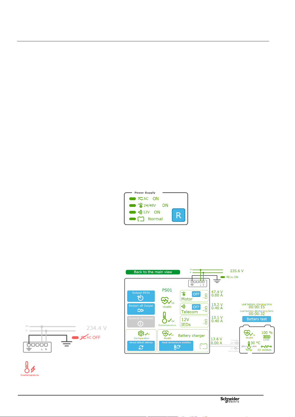
Information displayed for the PS50 Module
This graphical representation contains the following information:
The status of the power supplies managed by the PS50 module, respectively:
The AC line supply
The 24/48 VDC power supply for the switch motor mechanism
The 12 VDC power supply for the transmission equipment
The battery
A Reset button for restarting the power supplies in the event of an outage
following a potential issue on one of the outputs
Power supply shutdown
A power supply shutdown occurs when the mains power supply has been switched
off for a long time, in order to limit the time on the backup power supply (battery).
This power interruption preserves the capacity of the battery and its lifetime.
Battery backup saving can be enabled or disabled by configuration.
When this function is enabled, as soon as the MV network is switched off, the
battery takes over the power supply for a configurable maximum period Backup
time duration (default: 16 hours).
Beyond this period, an immediate alarm General shutdown is activated and then
Power supply is switched off automatically. The power supply is also switched off if
the battery reachs low level and then PS50 module enters sleep mode until the AC
network voltage returns.
From this sleep mode, the 24/48 V & 12 V power supply outputs can be
reactivated temporarily when the PS50 module is reset (Reset button
the External Reset digital input of the PS50 module is activated. The power
supply is switched off again and permanently if it reach the critical discharge
threshold (< 10.8 V).
Extended display for the PS50 Module
By clicking on the graphical representation of the PS50 above, additional
information appears on the right-hand side of the screen including states,
measurements, and the possible actions.
) or when
Examples of potential issues displayed in red
NT00378-EN-03
Under normal conditions, the information is displayed in green. In the event of an
anomaly, the information is displayed in orange or red depending on the severity of
the condition.
19

Commissioning Data Consultation and Monitoring
pages
A Reboot PS50 button for restarting the PS50 module. This action performs a complete reboot of
the T300 device.
The extended information included in the detailed view of the PS50 module is
described in the table below:
A Restart all outputs button for restarting all outputs. This may reset the outputs to their initial state
if this is possible and if the anomaly is temporary.
A General shutdown button that can only be activated if there is no AC line supply and power is
supplied by the battery only. Click this button to switch all T300 power supplies to standby mode
and thereby conserve battery power. It is possible to exit standby mode, either manually by pressing
the Reset button on the front of the PS50, or automatically when the AC line supply is restored.
A Reload default settings button for clearing the current parameters and returning to the
PS50 module default parameters.
A Health symbol indicating the overall state of the PS50 and an Overtemperature symbol indicating
the state of the PS50 module thermal protection.
A symbol indicating the state of the 24/48 V switch motor mechanism power supply with an
ON/OFF button for turning this power supply on or off.
A voltage measurement and a consumption measurement are also displayed for this power supply.
A symbol indicating the state of the 12 V transmission power supply with an ON/OFF button for
turning this power supply on or off.
A voltage measurement and a consumption measurement are also displayed for this power supply.
A symbol indicating the state of the general 12 V power supply for the T300 modules and IEDs.
A voltage measurement and a consumption measurement are also displayed for this power supply.
This section displays the overall state of the battery charger with a Reset temperature
statistics button to clear the stored minimum and maximum battery temperatures.
A voltage measurement and a consumption measurement are also displayed for the battery.
A symbol for the presence/absence of the AC line supply with the corresponding voltage
measurement.
Two time indications and a button:
Last battery charging time: Duration of the battery's last charging period
Last battery discharging time: Duration of the battery's last discharging period
Battery test button for activating the battery test immediately. The battery test is theoretically
conducted automatically depending on the period defined in the Automatic test
interval parameter (default setting: 1 day).
Note : The button is not displayed if the battery is disconnected, if battery
potential issue is detected, or if the AC supply is missing.
A graphical representation of the overall status of the battery, including:
Overall battery health indication
Percentage battery charge remaining
Internal resistance measurement in mOhm
The temperature measured in the PS50 operating environment (measurement made internally
in the PS50 box) with an indication of the minimum and maximum values recorded since the
last statistics reset (see
An indication of whether the battery is charging or discharging via arrows showing the direction
of the current. The measurement indicated at the charger level (see
value for this current.
)
) gives a measurement
20
NT00378-EN-03

Commissioning Data Consultation and Monitoring
r
r
r
pages
Information displayed for the SC150 modules
Each switch managed by a SC150 module is represented graphically with the
following indications:
Position of the switch (open or closed)
Position of the ground switch (open or closed)
Presence of the MV voltage (ON or OFF)
Display of the RMS current and voltage measurements for each phase
Indication of the presence of a fault current by a red flash and an arrow
indicating the direction of the fault current (for directional fault current detection):
o Green arrow = in the direction of the busbar
o Red arrow = in the direction of the network
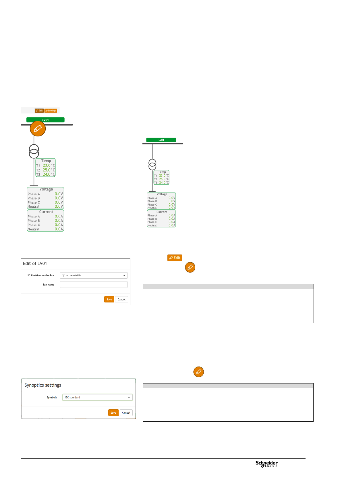
Button for editing the graphics parameters associated
with switches
Window for setting the parameters of the graphic
objects associated with a switch
Graphical representation of the Switch
It is possible to customize the graphical representation of each switch by clicking
the button at the top of the page.
Click the edit button that appears in the page to access the graphic
parameters for the switch you want to customize.
A window appears offering the following choices:
Parameter Possible choices Description
SC Position on the bus
Switch type
Line output
VT presence
CT presence
Bay name Name given to the channel
Not connected
On the left
On the right
In the middle
Disconnector
Load switch
Switch disconnector
Circuit breaker
Not any output
Cable
LV0x
No
Yes
No
Yes
Choice of position of the switch on
the busbar:
No link with the busbar
On the left
On the right
In the middle
Choice of switchgear represented:
Disconnector
Load switch
Switch disconnector
Circuit breake
Choice for the representation of
the line downstream of the switch
Choice of whether or not to display
the voltage measurement
transforme
Choice of whether or not to display
the current measurement
transforme
NT00378-EN-03
21

Commissioning Data Consultation and Monitoring
pages
Dummy switch
position
Dummy switch position LED on the front panel of the
SC150 module
Extended display for the SC150 module
By clicking on the graphical representation of the switch, additional information
appears on the right-hand side of the screen including counters
and measurements:
Information relating to the switch is displayed in the same way as in the
standard representation. There is also an option to send a command to the
switch by clicking the or button (depending on its
actual position). The graphical representation of the switch is automatically
updated as soon as the change of state is detected.
The general fault current counters representing the total number of phase-to-
phase and phase-to-ground (earth) fault currents detected are displayed by type
(transient, semi-permanent, and permanent), with the option to reset the counter
values by clicking the Reset button .
The detected phase-to-phase fault current counters are displayed by type
(transient, semi-permanent, and permanent), with the option to change the values
by clicking the Edit button.
The detected phase-to-ground (earth) fault current counters are displayed by
type (transient, semi-permanent, and permanent), with the option to change the
values by clicking the Edit button.
The number of operations counted on the switch is given, with the option to
change the value by clicking the Edit button .
The T300 includes the option to configure 2 sets of fault current detection
parameters (with specific values for each set) in the Settings section of the Web
server (see the corresponding section in this manual). The option is given here to
select which set of parameters to apply to fault current detection by clicking or
. The active group is indicated by a green LED.
A Simulation section that is used to test a command on a dummy switch
without actually actuating it (this can be useful to test T300-SCADA
communication when it is not physically possible to operate the switch due to an
interruption on the MV network). To do this, click on the or
retransmission of the change of state remotely (e.g. at the SCADA end). The
position of the dummy switch changes state in this Simulation section of the
application but the actual position of the MV switch (indicated in
change.
After a command is sent to the dummy switch, its position is indicated for
30 seconds on the first customized LED on the SC150 module.
button to operate dummy switch and, for instance, check the
) does not
The instantaneous current measurements for each phase as well as the
residual current
The instantaneous voltage measurements for each phase.
22
NT00378-EN-03
Commissioning Data Consultation and Monitoring
pages
Information displayed for the LV150 modules
Each LV150 module has its own graphical representation including the display of
the following information:
The temperature measurements provided by the three PT100 sensors
connected to the LV150
The LV current measurements on each phase and neutral
The LV voltage measurements on each phase and neutral.
Note: The neutral current measurement displayed corresponds to a measured
value in case the 3-phase + neutral sensors mounting is used and to a calculated
value (by summing all 3 phases) when the neutral is not connected.
Button for editing the graphics parameters associated
with LV150
Window for setting the parameters of the graphic
objects associated with LV150
Window for selecting the standard for the graphical
representations
Graphical representation of LV150:
It is possible to customize the graphical representation of each LV150 module by
clicking the button at the top of the page.
Click the edit button that appears in the page to access the graphic
parameters for the LV150 you want to customize.
A window appears offering the following choices:
Parameter Possible choices Description
LV Position on
the bus
Bay name Name given to the channel
Synoptics settings
Click the settings button to define the type of graphical representation to
apply for the objects displayed in the page's synoptics:
Parameter Possible choices Description
Symbols
Not connected
On the left
On the right
In the middle
IEC standard
ANSI standard
Choice of position of the LV150 on the
busbar:
No link with the busbar
On the left
On the right
In the middle
The standard used relates to the representation of
the switchgear, voltage and current transformers,
and the ground switch:
Objects represented in accordance with the IEC
standard.
Objects represented in accordance with the
ANSI standard.
NT00378-EN-03
23

Commissioning Data Consultation and Monitoring
pages
Monitoring & Control/Physical view page – Web server
Overall HU250 module status
Overall PS50 module status
3.1.3 System Page
Accessed via: Monitoring & Control/System page
This page provides a general overview of the system. The states of the various
items (modules) are given by symbols indicating a correct operation or potential
issue conditions. The indications given by theses states are detailed by module
here after.
HU250 Module Status
This representation includes:
The status of the Wi-Fi access and the K7 3G/4G modem with a 5-bar GSM
signal strength indicator, and indication of the IP address if connected to the
mobile network.
The status of the HU250 module itself, including the configuration, the PLC,
the GPS reception, the synchronization of equipment and a percentage value
representing the CPU usage level.
Note: The GPS reception symbol indicates the satus of GPS reception with a
color:
- gray: unconfigured or invalid GPS reception.
- green: operational GPS reception.
- red: GPS reception potential issue.
Note 2: A GPS reception issue causes a loss of synchronization and the
corresponding symbol becomes red.
PS50 Module Status
This representation includes:
An indication of the type of link used for the internal HU250-PS50 link (RS485
in Modbus protocol).
The status of the PS50 module, the charger, and the battery, as well as the
overall status of the internal Modbus RS485 link.
LV150 and SC150 Modules Status
This representation includes:
An indication of the type of link used for the internal link between HU250
module and SC150/LV150 modules (Ethernet LAN in IEC 60870-5-104 protocol).
The status of the SC150 and LV150 modules, including for each the status of
the configuration and synchronization, as well as the overall status of the internal
IEC 60870-5-104 Ethernet LAN.
Overall SC150 and LV150 modules status
24
NT00378-EN-03

Commissioning Data Consultation and Monitoring
pages
Example of a pop-up window displayed for the
Configuration section of a module
Example of a pop-up window displayed for the
Synchronization section of a HU250 module and
SC150/LV150 module
Example of a pop-up window displayed for the Modem
section of a module
Example of shortcuts available by clicking on the
module representation
Extended display
By passing the mouse over some graphical elements of the modules in the System
page, a "pop up" window appears giving additional indications.
This additional display concerns the following:
1. Configuration: By passing the mouse over the Conf element of a module,
the system indicates the following informations:
The minimum software required for compatibility with the module
configuration.
The options installed on the module (eg details of installed power
2. Synchronization: By passing the mouse over the Synchro element of a
3. Modem: by passing the mouse over the graphical representation of a 3G/4G
measurement options).
module, the system gives the following indications:
For the HU250 module:
o Status of the two synchronization sources (primary and secondary).
For the SC150 and LV150 modules:
o Status of the module time synchronization and status of the
synchronization source generating this synchronization.
o Status of the "1Hz" module synchronization as well as the status of
this synchronization 1Hz signal. This synchronization allows all the
SC150 and LV150 modules to be synchronized to the same 1 Hz
frequency top generated by the HU250 module.
modem, the system indicates the following informations:
Type of modem installed (2G, 3G or 4G modem).
Received GSM signal strength, numbered from 0 to 99:
o 0 to 10: insufficient GSM reception
o 11 to 31: correct GSM reception
o 99: undetectable GSM signals.
The IP address obtained for the T300, assigned by the mobile operator.
The modem IMEI code, allowing identification of the equipment
connecting to the mobile network.
Shortcut to pages
By clicking on the graphical representation of a module, a pop-up window appears
giving the possibility to access directly certain pages of the Web server linked to
this module, like shortcuts or quick accesses.
Depending on the type of module, quick access can be of different types:
PS50: shortcuts to the PS50 module configuration page (Settings page) and
the PS50 module status display page (Subview of PS page).
Other modules: shortcuts to the system events page (Diagnostics-
>System page) and the module settings page (Settings page).
NT00378-EN-03
25

Commissioning Data Consultation and Monitoring
pages
Monitoring & Control / Status page – Web server
3.1.4 Data Pages
Accessed via: Monitoring & Control/Status-Command-Analog-Setpoint page
There are 4 pages in the T300 Web server for viewing status and measurement
data or for sending commands:
Status page: For viewing the status of the digital data
Command page: For sending change of state commands based on the
digital data
Analog page: For viewing measurement values
Setpoint page: For forcing parameter values
Each page has the same format, with the following information displayed on
the screen:
The data refresh period can be configured in 1 of 3 ways:
o Fast: Data is refreshed every second
o Normal: Data is refreshed every 4 seconds
o Slow: Data is refreshed every 10 seconds
It is also possible to set a filter to display data by Source or Destination to limit
the amount of data displayed on screen:
The description of a data item is displayed over 3 main columns:
o Point name Internal name of the data item in CoreDb (database)
o Description Data label
o Value Value of the data item
By clicking the button associated with the Value field, you can manually
edit the state or value of a Command or Setpoint data item:
Note: For switch control, it is advisable to use the interface in the Substation view.
26
NT00378-EN-03

Commissioning Data Consultation and Monitoring
pages
Example of Analog data display
Similarly, for a Status or Analog data item, you can force its status or value.
However, this type of data is only processed in read mode; forcing is only
applied in simulation.
To do this, the actual data item must first be locked by clicking the Locking option.
Once the data is locked, the button associated with the Value field then
becomes accessible and can be used to change its status or value in
simulation mode.
Note: The modified value also impacts the remote retransmission at the
SCADA end. This allows you, for instance, to simulate the state of a variable
and to test its retransmission at the SCADA end, without affecting the actual
equipment operation.
Disabling the Locking option cancels the simulation and returns to the actual
status or value of the data item.
Two icons displayed in the Quality column provide an indication of the data
processing quality. The quality of a data item can give an indication of the
validity of the status or value entered on the Web server page.
This quality is indicated for the following 2 sources:
o Local source: Reflects the quality of the data item from the viewpoint
of its processing at the HU250 end
o Remote source: Reflects the quality of the data item sent by the
information source (device) processing the data (e.g. SC150, PS50, etc.)
NT00378-EN-03
In the same way as for a change of state or value for Status or Analog
it is possible to manually simulate the quality of a data item.
To do this you must first lock the data item using the Locking option,
then click the button associated with the Quality field.
The possible choices for the local and remote source quality are then displayed
on screen.
Disabling the Locking option cancels the simulation and returns to the actual
quality of the data item.
data,
27
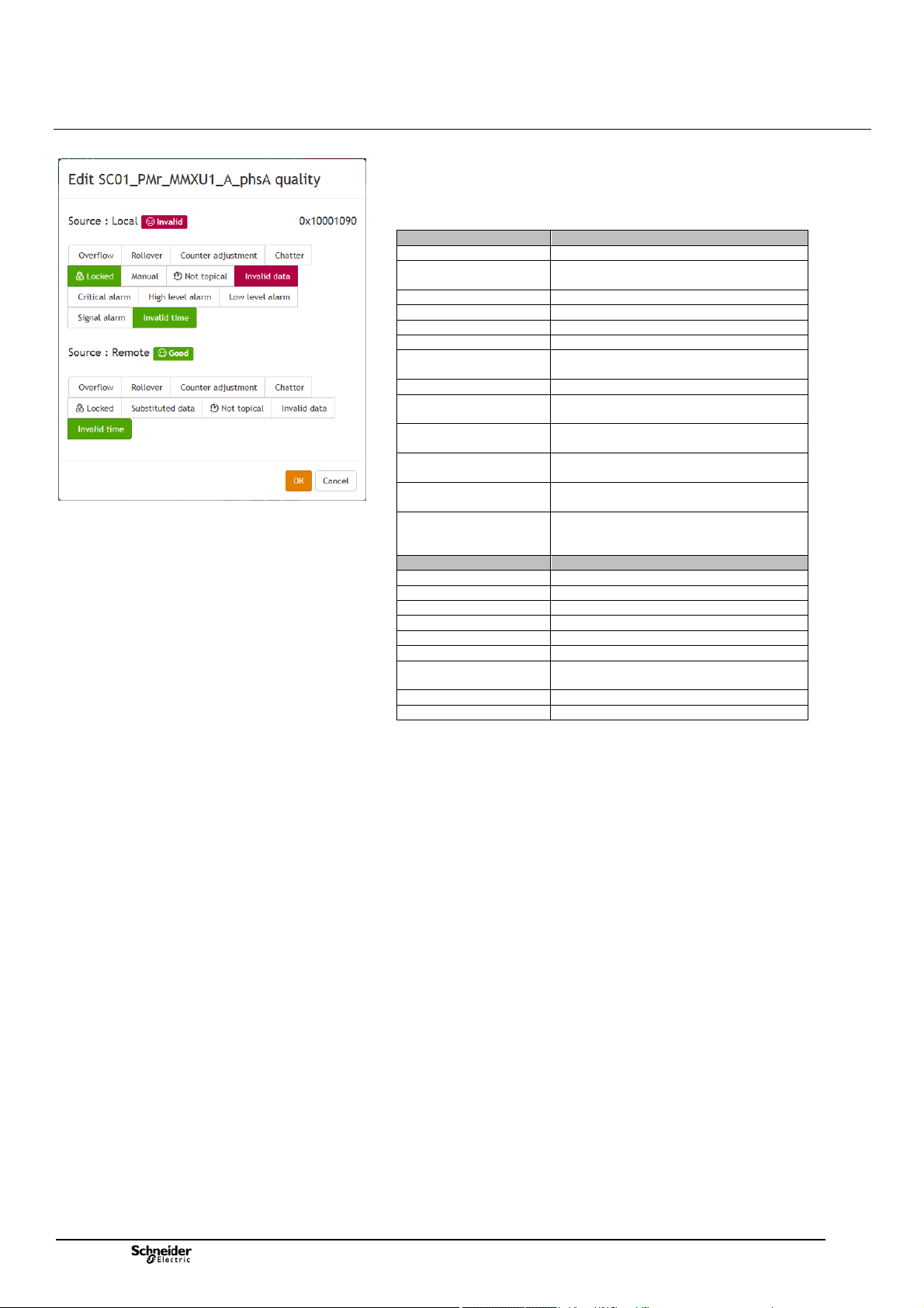
Commissioning Data Consultation and Monitoring
r
pages
Choice of quality options for the local and remote sources
The table below shows the correspondence of the different quality types that can
be simulated after having locked a data item.
Note that this also gives an indication of the different quality types that can be
obtained in actual operation:
Local source quality Description
Overflow An overflow has occurred on a counter
Rollover An overflow and an automatic reset have
Counter adjustment The counter has been adjusted
Chatter Excessive change on a digital input
Locked The data item is locked
Manual The data item has been manually replaced
Not typical The data item has not yet been written to
Invalid data Data item is invalid
Critical alarm The value of the data item has exceeded
High level alarm The value of the data item has exceeded
Low level alarm The value of the data item is below the Low
Signal alarm The value of the data item is below the
Invalid time The data item time-stamp is invalid or
Remote source quality Description
Overflow An overflow has occurred
Rollover A rollover has occurred on a counter
Counter adjustment The counter has been adjusted
Chatter Excessive change on a digital input
Locked The data item is locked
Substituted data The data item has been manually replaced
Not topical The data item has not yet been written
Invalid data Data item is invalid
Invalid time The data item time-stamp is invalid
occurred on a counte
the database
the High-High alarm threshold
the High alarm threshold
alarm threshold
Low-Low alarm threshold
inaccurate (the HU250 is not synchronized
by a source)
to the database
28
NT00378-EN-03

Commissioning The Measures
A
Example of measurements displayed – MV or LV
Measurement/PM – Power page / RMS tab
3.2 Measurements
3.2.1 Measurements Pages
Accessed via: MV and LV Measurements/PM-Power/PM-Energy/Power-Quality
page
The MV and LV Measurements pages in the Web server display the different
types of power, energy, and quality measurements taken by the T300 on the MV
and LV networks, in tabs including data tables based on the analog data received
from the current and voltage sensors.
Note: Regarding MV voltage measurement, the T300 takes the measurements
using the same current and voltage sensors as those used to detect fault currents.
The power and energy measurements comply with standard IEC 61557-12.
The power quality measurements are completed according to the principles of IEC
61000-4-30 class S (up to harmonic 15).
Note: To comply with the accuracy required by the standards (1% accuracy),
voltage measurements are only possible using LPVT or VT type adaptors (for LV
measurement; only Voltage adaptor type).
Some measurements are optional for the T300 ("option" column in the table
below). If the corresponding option is not present in the equipment, the associated
data is not displayed in the LV and MV Measurements pages.
Note: The PM option (and associated measurements) is included as standard for
LV measurements, although this is optional for MV measurements.
The data displayed in the MV Measurements page depends on the parameter
settings in the Settings/SC0x/Measurements and Power Quality pages.
The data displayed in the LV Measurements page depends on the parameter
settings in the Settings/LV0x/Measurements and Power Quality pages.
Refer to the corresponding sections for more information on how to configure
these parameters.
The list of measurements displayed in the MV and LV Measurements pages is
identical and shown below:
Category Measure Description Option
Current Mean Mean current on all 3 phases
Single
voltage
Phase
voltage
Real power Total Total active power
Reactive
power
Apparent
power
Power
factor
(*): PM option is incuded as standard for the LV measurements.
Phase A Current on phase A
Phase B Current on phase B
Phase C Current on phase C
Residual Residual current
Mean Mean phase-to-neutral voltage on all 3
phases
Phase A Phase-to-neutral voltage on phase A
Phase B Phase-to-neutral voltage on phase B
Phase C Phase-to-neutral voltage on phase C
Neutral Residual voltage
Mean Mean phase-to-phase voltage on all 3 phases
Vab Phase-to-phase voltage between phases A
and B
Vbc Phase-to-phase voltage between phases B
and C
Vca Phase-to-phase voltage between phases C
and
Phase A Active power on phase A
Phase B Active power on phase B
Phase C Active power on phase C
Total Total reactive power
Phase A Reactive power on phase A
Phase B Reactive power on phase B
Phase C Reactive power on phase C
Total Total apparent power
Phase A Apparent power on phase A
Phase B Apparent power on phase B
Phase C Apparent power on phase C
Total Total power factor
Phase A Power factor on phase A
Phase B Power factor on phase B
Phase C Power factor on phase C
Tab PM - Power
Tab RMS
No option
(included
as
standard)
PM option
(*)
NT00378-EN-03
29
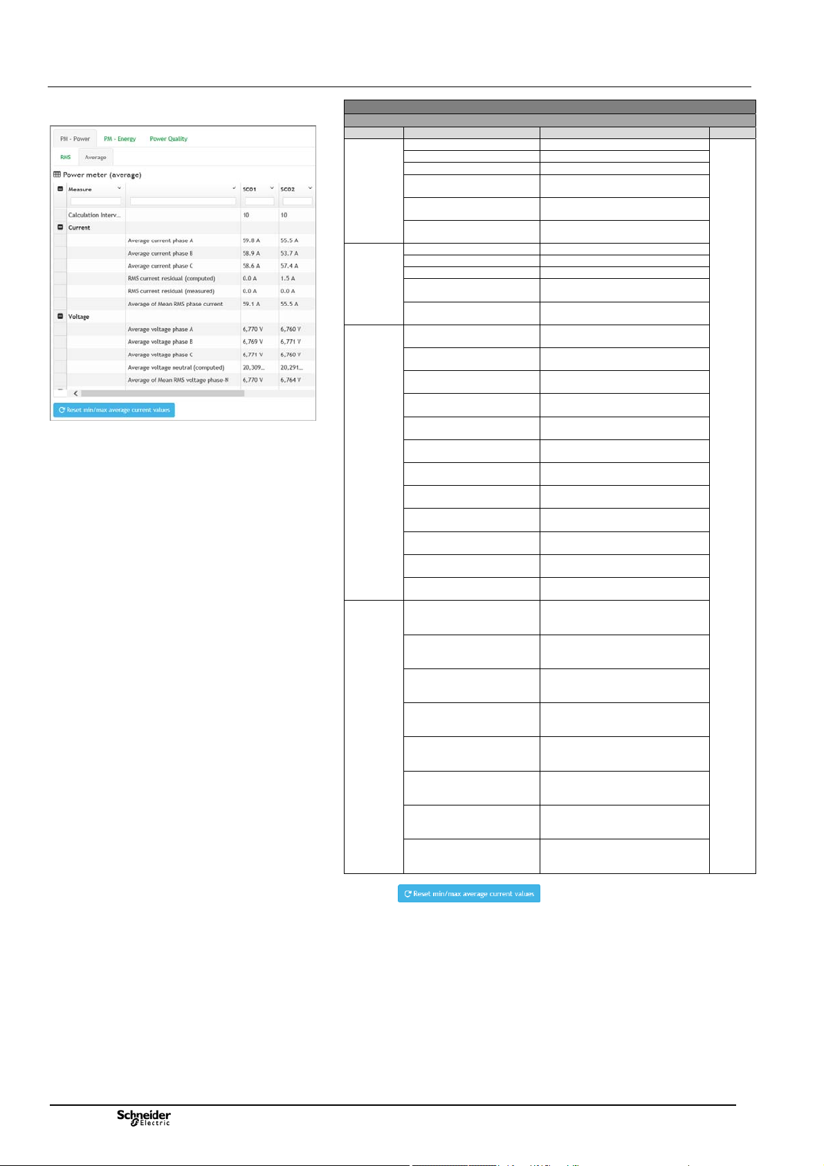
Commissioning The Measures
A
A
A
A
y
r
y
year
Example of measurements displayed – MV or LV
Measurement/PM – Power page / Average tab
Category Measure Description Option
Current Average current phase A Average current phase A
Voltage Average voltage phase A Average voltage phase A
Power Average P Real power
Min/Max
recording
(*): PM option is incuded as standard for the LV measurements.
(°) :A button on the page manually resets the calculated
averages on the currents.
Average current phase B Average current phase B
Average current phase C Average current phase C
RMS current residual
(computed)
RMS current residual
(measured)
Average of Mean RMS
phase current
Average voltage phase B Average voltage phase B
Average voltage phase C Average voltage phase C
Average voltage neutral
(computed)
Average of Mean RMS
voltage phase-N
phase
Average P Real power
phase B
Average P Real power
phase C
Average P Real power
total
Average Q Reactive
power phase
Average Q Reactive
power phase B
Average Q Reactive
power phase C
Average Q Reactive
power total
Average S Apparent
power phase
Average S Apparent
power phase B
Average S Apparent
power phase C
Average S Apparent
power total
Minimum of average of
Mean RMS phase current
da
Minimum of average of
Mean RMS phase current
week
Minimum of average of
Mean RMS phase current
month
Minimum of average of
Mean RMS phase current
yea
Maximum of average of
Mean RMS phase current
da
Maximum of average of
Mean RMS phase current
week
Maximum of average of
Mean RMS phase current
month
Maximum of average of
Mean RMS phase current
Tab PM - Power
Tab Average (°)
RMS current residual (computed)
RMS current residual (measured)
Average of Mean RMS phase
current
Average voltage neutral (computed)
Average of Mean RMS voltage
phase-N
Average P Real power phase A
Average P Real power phase B
Average P Real power phase C
Average P Real power total
Average Q Reactive power phase A
Average Q Reactive power phase B
Average Q Reactive power phase
C
Average Q Reactive power total
Average S Apparent power phase
Average S Apparent power phase
B
Average S Apparent power phase
C
Average S Apparent power total
Minimum of average of Mean RMS
phase current day
Minimum of average of Mean RMS
phase current week
Minimum of average of Mean RMS
phase current month
Minimum of average of Mean RMS
phase current year
Maximum of average of Mean RMS
phase current day
Maximum of average of Mean RMS
phase current week
Maximum of average of Mean RMS
phase current month
Maximum of average of Mean RMS
phase current year
PM
Option
(*)
30
NT00378-EN-03
 Loading...