


Schneider Electric TAC Xenta 102 Users Manual
Zone controller
TAC Xenta 102
Handbook
TAC improves indoor climate
and reduces operating costs.
Air flow |
Changeover via |
|
|
|
|
Heating |
network variable |
Cooling |
|
|
Cooling |
|
|
demand |
0-004-7516-1 (GB), 1999-08-18

TAC Xenta 102 Handbook |
Foreword |
Foreword
This is the technical handbook for the TAC Xenta 102 controller, a zone controller for VAV applications in offices and other larger buildings.
In this second edition of the handbook, sections that were earlier complicated to the user, have been made clearer, and most of the content has been reorganized. The trouble-shooting section has been made into its own chapter, and there are now appendices in the end of the handbook; one containing setpoint calculating examples, and one containing a commissioning protocol which can be used together with chapter 3 when commissioning.
The programs in TAC Xenta 102 now have new versions. For both the system program and the application program in the controller, the versions are 1.10. If there is a service replacement in the system, all variable bindings—if the controller is run on a network—must be remade when an older or newer version of the controller is fitted. This is because the controller has got a new “Standard Program ID”. There are also three new network variables.
TAC AB, 1999-08-18 |
0-004-7516-1 (GB), i (ii) |

TAC Xenta 102 Handbook |
Foreword |
Copyright © 1999 TAC AB
This document contains information which is the property of TAC and is therefore only available for those using and maintainingTAC’s equipment. Disclosure, reproduction or use of either the document or the information within for any other purpose are strictly prohibited.
TAC reservs the right to make necessary changes of and additions to the material.
Echelon, Lon, LonWorks, LonTalk, Neuron, 3150, LonMark and the LonMark logo are registered trademarks for Echelon Corporation, USA. TAC Xenta® is a registered trademark for TAC AB in Sweden and other countries. All other trademarks are the property of their respective owners.
Revisions list
Part number |
Comment |
Editor |
Date |
0-004-7516-0 |
First edition. |
KRRO |
1997-09-11 |
0-004-7516-1 |
Second edition. System and application program in a new |
SUWA |
1999-08-18 |
|
version 1.10. |
|
|
ii (ii), 0-004-7516-1 (GB) |
TAC AB, 1999-08-18 |

TAC Xenta 102 Handbook |
Contents |
Zone controller TAC Xenta 102
Handbook
Reservations for changes.
Contents
1 |
Introduction .................................................................................................................. |
1:1 |
1.1 |
The content of the handbook ............................................................................................................... |
1:1 |
1.2 |
Documentation .................................................................................................................................... |
1:2 |
1.3 |
Terminology ........................................................................................................................................ |
1:3 |
2 |
The zone controller TAC Xenta 102 ............................................................................ |
2:1 |
2.1 |
General ................................................................................................................................................ |
2:1 |
2.2 |
Wall modules ....................................................................................................................................... |
2:3 |
2.3 |
Applications ......................................................................................................................................... |
2:4 |
2.3.1 |
General ............................................................................................................................................... |
2:4 |
2.3.2 |
Air flow control only (TAC Xenta 102-B) ........................................................................................ |
2:4 |
2.3.3 |
Air flow control with modulating valve reheat (TAC Xenta 102-VF) ................................................ |
2:5 |
2.3.4 |
Air flow control with modulating valve water reheat and fan (TAC Xenta 102-VF) .................... |
2:5 |
2.3.5 |
Air flow control with one stage electric reheat (TAC Xenta 102-EF) ............................................. |
2:6 |
2.3.6 |
Air flow control with one stage electric reheat and fan (TAC Xenta 102-EF) ............................... |
2:6 |
2.3.7 |
Air flow control with thermo-actuator for radiators (TAC Xenta 102-EF) ................................... |
2:7 |
3 |
Installation |
.................................................................................................................... |
3:1 |
3.1 |
Mechanical installation ....................................................................................................................... |
3:1 |
|
3.1.1 |
Fitting .................................................................................................................................................. |
|
3:1 |
3.2 |
Electrical ..........................................................................................................................installation |
3:3 |
|
3.2.1 |
General ............................................................................................................................................... |
|
3:3 |
3.2.2 |
Wiring of ............................................................................................................. |
TAC Xenta 102 - B |
3:5 |
3.2.3 |
Wiring of .......................................................................................................... |
TAC Xenta 102 - EF |
3:6 |
3.2.4 |
Wiring of .......................................................................................................... |
TAC Xenta 102 - VF |
3:7 |
3.3 |
Commissioning ................................................................................................................................... |
3:8 |
|
3.3.1 |
General ............................................................................................................................................... |
|
3:8 |
3.3.2 |
Node status .......................................................................................................................................... |
3:8 |
|
3.3.3 |
Configuration ......................................................................................................parameters (nci’s) |
3:9 |
|
3.3.4 |
Network installation ......................................................................................................................... |
3:10 |
|
3.3.5 |
Network variable ................................................................................................................binding |
3:10 |
|
3.3.6 |
Function test ..................................................................................................................................... |
3:10 |
|
4 |
Configuration parameters ............................................................................................ |
4:1 |
4.1 |
Basic parameters ................................................................................................................................ |
4:2 |
4.2 |
Other configuration parameters ......................................................................................................... |
4:3 |
TAC AB, 1999-08-18 |
0-004-7516-1 (GB), 1 (2) |

TAC Xenta 102 Handbook Contents
5 |
Functional description ................................................................................................. |
5:1 |
5.1 |
General ................................................................................................................................................ |
5:1 |
5.2 |
The controller’s basic functions ............................................................................................ ............. |
5:2 |
5.2.1 |
Operation modes ................................................................................................................................ |
5:2 |
5.2.2 |
Operation mode, manual mode and emergency mode .................................................................... |
5:4 |
5.2.3 |
Measuring zone temperature ............................................................................................................ |
5:5 |
5.2.4 |
Setpoint calculation ........................................................................................................................... |
5:6 |
5.2.6 |
Control sequence with TAC Xenta 102-B ......................................................................................... |
5:8 |
5.2.5 |
Control sequence with TAC Xenta 102-EF and 102-VF .................................................................. |
5:8 |
5.3 |
More about functions ......................................................................................................................... |
5:10 |
5.3.1 |
Air flow control ................................................................................................................................ |
5:10 |
5.3.2 |
Heating and fan control ................................................................................................................... |
5:11 |
5.3.3 |
Air quality control ........................................................................................................................... |
5:12 |
5.3.4 |
Window contact ................................................................................................................................ |
5:13 |
5.3.5 |
Occupancy sensor ............................................................................................................................ |
5:13 |
5.3.6 |
Minimum value for heating valve (TAC Xenta 102-VF only) ...................................................... |
5:14 |
5.3.7 |
Alarm ................................................................................................................................................ |
5:15 |
5.3.8 |
Master/slave operation .................................................................................................................... |
5:16 |
6 |
Trouble-shooting ........................................................................................................... |
6:1 |
6.1 |
General ................................................................................................................................................ |
6:1 |
6.2 |
Inputs and outputs (nvi/nvo’s) .............................................................................................................. |
6:2 |
6.3 |
Problems and solutions ....................................................................................................................... |
6:3 |
7 |
Technical data ............................................................................................................... |
7:1 |
7.1 |
Technical data ...................................................................................................................................... |
7:1 |
7.2 |
Dimensions .......................................................................................................................................... |
7:3 |
7.2.1 |
With semi-protection ......................................................................................................................... |
7:3 |
7.2.2 |
Without semi-protection .................................................................................................................... |
7:3 |
8 |
Communication ............................................................................................................. |
8:1 |
8.1 |
General ................................................................................................................................................ |
8:1 |
8.2 |
Default settings and power on ............................................................................................................. |
8:1 |
8.3 |
Monitoring network variables, Heartbeat ........................................................................................... |
8:2 |
8.4 |
Not accepted values .............................................................................................................................. |
8:3 |
8.5 |
The node object .................................................................................................................................... |
8:3 |
8.5.1 |
The node object’s inputs (nvi) ............................................................................................ ................ |
8:3 |
8.5.2 |
The node object’s outputs (nvo) ........................................................................................... .............. |
8:4 |
8.5.3 |
The node object’s configuration parameters (nci) ........................................................................... |
8:4 |
8.6 |
The controller object ........................................................................................................................... |
8:4 |
8.6.1 |
The controller object’s inputs (nvi) ...................................................................................... ............. |
8:6 |
8.6.2 |
The controller object’s outputs (nvo) ................................................................................................ |
8:7 |
8.6.3 |
The controller object’s configuration parameters (nci) .................................................................. |
8:8 |
Appendix A: Setpoint calculation
Appendix B: Commissioning protocol
Index
Reply form
2 (2), 0-004-7516-1 (GB) |
TAC AB, 1999-08-18 |

TAC Xenta 102 Handbook |
About this handbook |
1 Introduction
1.1The content of the handbook
•Chapter 1 Introduction,
gives an overview over the structure of this handbook, additional information about the product, and has a short terminology section.
•Chapter 2 The zone controller TAC Xenta 102,
briefly describes the wall module, the controller’s functions and control examples of the three different models of TAC Xenta 102.
•Chapter 3 Installation,
contains instructions on mechanical and electrical installation of the controller, and instructions on commissioning and network installation.
•Chapter 4 Configuration parameters,
describes the setting of the zone controller’s configuration parameters.
•Chapter 5 Functional description,
gives detailed information about the zone controller’s basic functions, operating modes, and other functions.
•Chapter 6 Trouble-shooting during operation and commissioning,
contains trouble-shooting measures you can use to find and remedy possible faults in the system.
•Chapter 7 Technical data,
lists all technical data and dimensions for TAC Xenta 102.
•Chapter 8 Communication,
describes the zone controller’s communication with other units via the network by means of network variables.
•Appendix A, Setpoint calculation
contains calculating examples for the setpoint calculation in chapter 5.
•Appendix B
contains a commissioning protocol, which can be used together with chapter 3 during installation and commissioning.
TAC AB, 1999-08-18 |
0-004-7516-1 (GB), 1:1 (4) |

TAC Xenta 102 Handbook |
About this handbook |
•Index and Reply form,
are in the end of the handbook. Use the index to make your search for information easier, and the reply form to let us know whether there is something wrong or unclear in this handbook.
1.2Documentation
Enclosed documentation
TAC Xenta 102 is delivered with an installation instruction for each of the controllers below:
•TAC Xenta 102-B,
Installation instruction, part number 0FL-3857
•TAC Xenta 102-EF,
Installation instruction, part number 0FL-3859
•TAC Xenta 102-VF,
Installation instruction, part number 0FL-3861
Other documentation
There is additional information about TAC Xenta 102 in the following documents:
•Data sheet for TAC Xenta 102-B, part number 0-003-1611
•Data sheet for TAC Xenta 102-EF, part number 0-003-1617
•Data sheet for TAC Xenta 102-VF, part number 0-003-1623
•Data sheet for ZS 101–ZS 105,
part number 0-003-1661. Here the wall modules are described.
•TAC Xenta Network Guide,
part number 0-004-7460. Here you can find additional information on network installation.
•TAC Xenta OP Handbook,
part number 0-004-7506. Here you find information on how to use TAC Xenta OP together with TAC Xenta 102 and the wall modules.
•TAC Xenta, Zone System Guidelines
part number 0-004-7637. Here you find information on how a zone system is built with TAC Xenta components.
•TAC Xenta 102 Handbook,
part number 0-004-7516-0. Here you find information on the earlier version of the zone controller.
All the above mentioned documents can be found on the internet: www.tac.se or they can be ordered from the nearest TAC service point.
1:2 (4), 0-004-7516-1 (GB) |
TAC AB, 1999-08-18 |

TAC Xenta 102 Handbook |
About this handbook |
1.3 Terminology
In this handbook there are some abbreviations and terms which are specific for the zone controller’s applications and network communication. Therefore, the most common terms have been gathered, together with a short explanation, in the list below.
neuron .................. |
communication processor with built-in |
|
protocol |
node ..................... |
communication unit on the network |
SNVT ................... |
Standard Network Variable Type |
nvixxx .................. |
variable which gets its value from another |
|
unit on the network |
nvoxxx ................. |
variable which value is sent out to another |
|
unit on the network |
ncixxx .................. |
configuration parameter; variable which gets |
|
its value from another unit on the network |
|
and which keeps it during a power failure |
service pin ........... |
function which can be used during installation |
|
on the network |
wink ..................... |
confirmation that the connection to a controller |
|
via the network is working (a light emitting |
|
diode is lit for appr. 15 seconds) |
LNS ...................... |
LonWork Network Services. System tool for |
|
installation, configuration and maintenance of |
|
LonWorks network |
TAC AB, 1999-08-18 |
0-004-7516-1 (GB), 1:3 (4) |

TAC Xenta 102 Handbook |
About this handbook |
This page is intentionally left blank.
1:4 (4), 0-004-7516-1 (GB) |
TAC AB, 1999-08-18 |
TAC Xenta 102 Handbook |
The zone controller TAC Xenta 102 |
2 The zone controller TAC Xenta 102
2.1 General
The zone controller TAC Xenta 102 is intended for “Variable Air Volume” (VAV) applications in offices and other large buildings. A VAV controller usually controls the temperature in a given zone by controlling the volume sub-tempered air which is supplied to the zone.
The controller’s basic functions
All controller models have a number of built-in functions which handle the normal control situation. There are four operating modes to choose from (comfort, economy, bypass, and off) and five modes to force the controller (only heating allowed, only cooling allowed, night cooling, auto, and off).
Measuring the zone temperature is made by means of a permanent thermistor sensor or a temperature node connected to the network, and setpoint calculation is made according to special methods.
There is a detailed functional description of all the basic functions in chapter 5.2.
More about functions
Apart from the controller’s basic functions, there are additional possibilities to control the climate in the zone. In section 5.3, these are described in detail, and also which external functions that may be connected, e.g. window contact sensor and occupancy sensor.
TAC AB, 1999-08-18 |
0-004-7516-1 (GB), 2:1 (8) |
TAC Xenta 102 Handbook |
The zone controller TAC Xenta 102 |
Communication possibilities
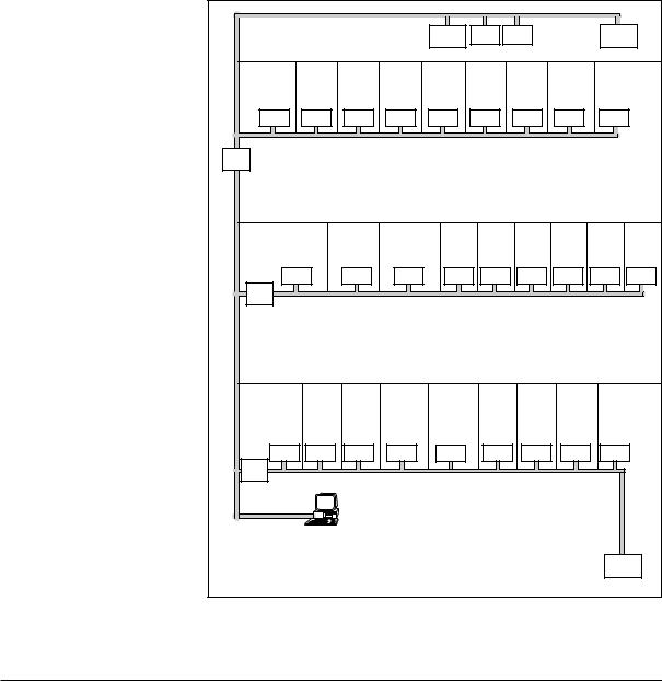
The controller can work either as a free-standing unit, without being connected to a network during operation, or be a part of a larger system with several other units such as TAC Xenta 300/400 and other zone controllers in the TAC Xenta family (figure 2.1). A detailed description of how units work together in a larger zone system, is found in “Guide lines for zone applications”, part number 0-004-7637.
TAC Vista is an excellent tool for reading variables and as a configuration tool during commissioning and/or operation. When TAC Vista is not a part of the system, reading and configuration of variables can be made from the operating panel TAC Xenta OP, version 3.11 or later.
4th |
|
|
|
|
|
|
|
|
|
|
|
|
|
|
|
floor |
|
|
|
|
|
TAC |
Digital |
Analog |
|
|
TAC |
|
|||
|
|
|
|
|
Xenta |
|
I/O |
|
I/O |
|
|
Xenta |
|
||
|
|
|
|
|
|
300 |
|
|
|
|
|
|
|
400 |
|
3rd |
Office 3:1 |
Office 3:2 |
Office 3:3 |
Office 3:4 |
Office 3:5 |
Office 3:6 |
|
|
Office 3:7 |
Office 3:8 |
|
Office 3:9 |
|||
floor |
|
|
|
|
|
|
|
|
|
|
|
|
|
|
|
|
101-1VF |
101-1VF |
101-1VF |
101-1VF |
101-1VF |
101-1VF |
|
101-1VF |
101-1VF |
|
101-2VF |
|
|||
Router |
|
|
|
|
|
|
|
|
|
|
|
|
|
|
|
2nd |
Room 2:1 |
Room 2:2 |
Room 2:3 |
Office 2:1 |
Office 2:2 |
|
Office 2:3 |
Office 2:4 |
|
Office 2:5 |
Office 2:6 |
||||
floor |
|
Master |
Slave |
Slave |
|
|
|
|
|
|
|
|
|
|
|
|
|
|
|
|
|
|
|
|
|
|
|
|
|
|
|
|
102-B |
102-B |
102-B |
|
101-2VF |
101-2VF |
|
101-2VF |
101-2VF |
101-2VF |
101-2VF |
||||
|
Router |
|
|
|
|
|
|
|
|
|
|
|
|
|
|
1st |
Room |
Room 1:2 |
Room 1:3 |
Room |
|
Room 1:5 |
Office 1:1 |
Office 1:2 |
Office 1:3 |
Office 1:4 |
|||||
floor |
1:1 |
Slave |
Slave |
1:4 |
|
Master |
|
|
|
|
|
|
|
|
|
Slave |
|
|
Slave |
|
|
|
|
|
|
|
|
|
|
|
|
|
102-EF 102-EF |
102-EF |
102-EF |
|
102-EF |
|
103-A |
|
|
103-A |
103-A |
|
103-A |
|
|
Router |
|
|
|
|
|
|
|
|
|
|
|
|
|
|
|
|
|
|
TAC Vista |
|
|
|
|
|
|
|
|
|
|
|
|
Ground |
|
|
|
|
|
|
|
|
|
|
|
|
|
TAC |
|
floor |
|
|
|
|
|
|
|
|
|
|
|
|
|
||
|
|
|
|
|
|
|
|
|
|
|
|
|
Xenta |
||
|
|
|
|
|
|
|
|
|
|
|
|
|
|
400 |
|
Figure 2.1 Zone controller in a larger system together with TAC Vista
2:2 (8), 0-004-7516-1 (GB) |
TAC AB, 1999-08-18 |
TAC Xenta 102 Handbook |
The zone controller TAC Xenta 102 |
The controller is LONMARK® approved and communicates on a
LONTALK® TP/FT-10 network via a twisted-pair, unpolarized cable.
2.2 Wall modules
Locking screw
|
COMFORT |
Bypass key |
ECONOMY |
OFF |
Setpoint knob
OP connection Position indicator
Figure 2.2 Wall module in the ZS100 series
In the controlled zone, there is usually a wall module from the ZS 100 series, which measures the temperature. The wall modules ZS 101–ZS 105 may very well be used together with all controller models. On the wall module (figure 2.2) there are among other things a setpoint knob and a bypass key with setting possibilities.
The setpoint knob is used to adjust the zone temperature setpoint with a maximum of ± 5 °C.
The bypass key is used to change the operating mode, and by pressing the key, an internal timer in the controller, which runs for two hours, is started. Read more about different operating modes and ways to force the controller in sections 5.2.1–5.2.2.
On all ZS 100 wall modules, the current operating mode is indicated by the position indicator (red light emitting diode) as follows:
·Steady light:
·Slow flashing:
·Fast flashing for appr. 15 s:
·Off:
Comfort or bypass mode Economy mode
Answer to “wink” command. Confirmation that the OP is connected to the correct controller
Other operating modes
There is additional information on the wall modules and how the temperatures can be adjusted locally in the zone by means of the keys in “Data sheet for ZS 101–ZS 105”, part number 0-003- 1661.
TAC AB, 1999-08-18 |
0-004-7516-1 (GB), 2:3 (8) |
TAC Xenta 102 Handbook |
The zone controller TAC Xenta 102 |
2.3 Applications
2.3.1 General
All models have this in common:
•they are intended for use together with a Belimo® VAV-Compact air flow controller. TAC Xenta 102 sends air flow setpoints to the VAV-Compact, and reads measured air flow from the air flow controller.
•they have air quality control as an option, which means that the controller can control the air flow to keep down the carbon dioxide concentration in the zone. However, the function needs a carbon dioxide sensor to be connected to the controller, electronically or via the network.
•a window contact to stop the heating and cooling functions, should a window be opened, can be connected. An occupancy sensor can detect the presence of a person in the controlled zone and change the controller from economy to comfort mode.
The window contact sensor, occupancy sensor, and air quality control are described in detail in section 5.3.2–5.3.4.
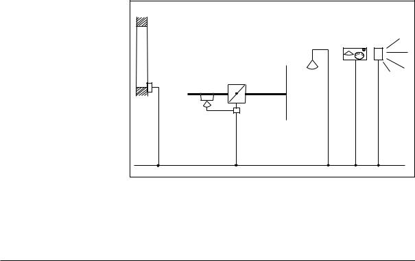
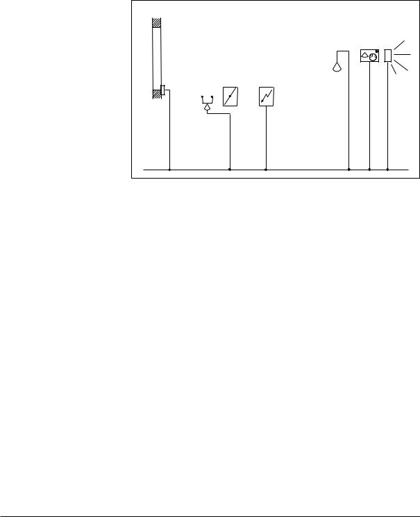
2.3.2 Air flow control only (TAC Xenta 102-B)
The controller controls the zone temperature by means of the air damper via VAV-Compact. The air flow is minimum and maximum limited. Usually the controller only uses one cooling sequence (sub-tempered air in the duct), but it can be changed to heating (hot air in the duct) given a central command.
| <![if ! IE]> <![endif]>dioxide |
|
| <![if ! IE]> <![endif]>Carbon |
<![if ! IE]> <![endif]>sensor |
Damper and air Window flow controller contact
Wall module
| <![if ! IE]> <![endif]>Occupancy |
<![if ! IE]> <![endif]>sensor |
Figure 2.3 Control application for TAC Xenta 102-B
2:4 (8), 0-004-7516-1 (GB) |
TAC AB, 1999-08-18 |
TAC Xenta 102 Handbook |
The zone controller TAC Xenta 102 |
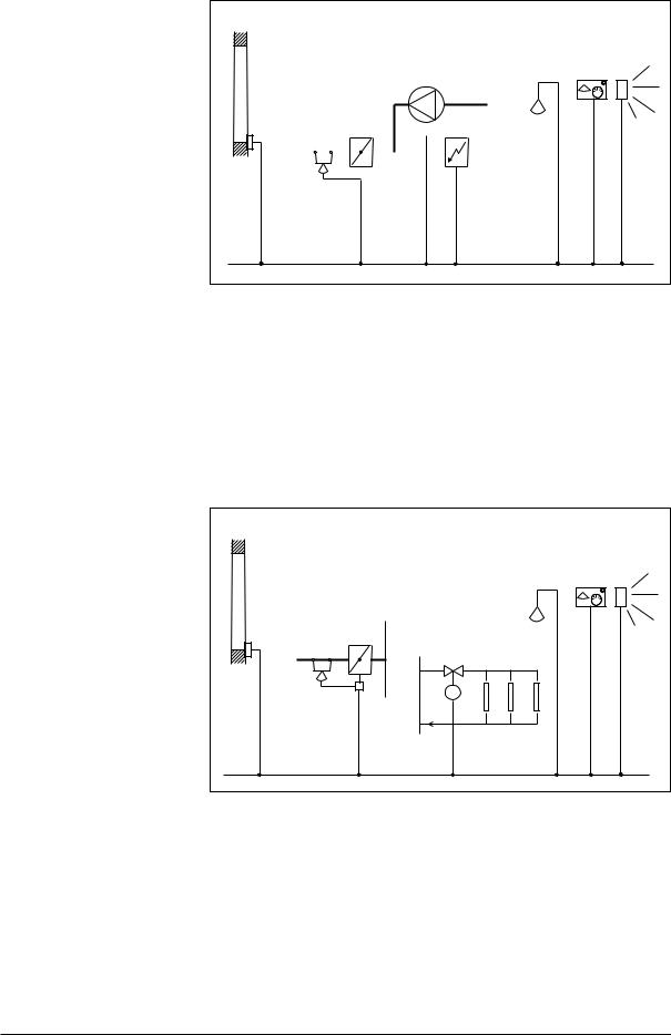
2.3.3 Air flow control with modulating valve water reheat (TAC Xenta 102-VF)
The controller controls the zone temperature by sequence controlling the air flow controller (VAV-Compact) and the heating coil. The air flow is minimum and maximum limited. The heating sequence controls the valve and minimum limits the air flow.
| <![if ! IE]> <![endif]>dioxide |
|
| <![if ! IE]> <![endif]>Carbon |
<![if ! IE]> <![endif]>sensor |
Window |
Damper and air |
Heating |
||||
flow controller |
water coil |
|||||
contact |
||||||
|
|
|
|
|
||
|
|
|
|
|
|
|
|
|
|
|
|
|
|
|
|
|
|
|
|
|
Wall module
| <![if ! IE]> <![endif]>Occupancy |
<![if ! IE]> <![endif]>sensor |
Valve and actuator
Figure 2.4 Control application for TAC Xenta 102-VF
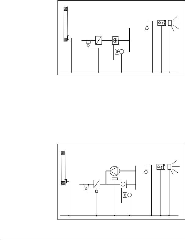
2.3.4 Air flow control with modulating valve water reheat and fan (TAC Xenta 102-VF)
The controller controls the zone temperature by sequence controlling the air flow controller (VAV-Compact) and the heating coil. The airflow is minimum and maximum limited. The heating combines the valve control with the fan to increase the air circulation through the heating coil.
|
|
Fan |
|
Window |
Damper and air |
Heating |
|
flow controller |
water coil |
||
contact |
|||
|
|
| <![if ! IE]> <![endif]>dioxide |
|
| <![if ! IE]> <![endif]>Carbon |
<![if ! IE]> <![endif]>sensor |
Wall module
| <![if ! IE]> <![endif]>Occupancy |
<![if ! IE]> <![endif]>sensor |
Valve and actuator
Figure 2.5 Control application for TAC Xenta 102-VF
TAC AB, 1999-08-18 |
0-004-7516-1 (GB), 2:5 (8) |
TAC Xenta 102 Handbook |
The zone controller TAC Xenta 102 |
2.3.5 Air flow control with one stage electric reheat (TAC Xenta 102-EF)
The controller maintains the zone temperature by sequence controlling the air flow controller (VAV-Compact) and the electric heating coil. The air flow is minimum and maximum limited. When heating, the controller controls the electric heating coil via a relay in combination with setting the air flow to its minimum value.
| <![if ! IE]> <![endif]>dioxide |
|
| <![if ! IE]> <![endif]>Carbon |
<![if ! IE]> <![endif]>sensor |
Window |
Damper and air |
Electric |
||||
flow controller |
heating coil |
|||||
contact |
||||||
|
|
|
|
|
||
|
|
|
|
|
|
|
|
|
|
|
|
|
|
|
|
|
|
|
|
|
|
|
|
|
|
|
|
|
|
|
|
|
|
|
Wall module
| <![if ! IE]> <![endif]>Occupancy |
<![if ! IE]> <![endif]>sensor |
Figure 2.6 Control application for TAC Xenta 102-EF
2.3.6 Air flow control with one stage electric reheat and fan (TAC Xenta 102-EF)
The controller controls the zone temperature by sequence controlling the air flow controller (VAV-Compact) and the electric heating coil. The air flow is minimum and maximum limited. When heating, the controller controls the electric heating coil by means of a relay in combination with the fan running to increase the air circulation through the heating coil. In this application (electric reheat + fan), the minimum limitation may have separate settings for cooling and heating.
2:6 (8), 0-004-7516-1 (GB) |
TAC AB, 1999-08-18 |
TAC Xenta 102 Handbook |
The zone controller TAC Xenta 102 |
|
|
|
|
|
Fan |
||||
Window |
Damper and air |
|
|
|
|
El. heating |
|||
contact |
flow controller |
|
|
|
|
coil |
|||
|
|
|
|
|
|
|
|
|
|
|
|
|
|
|
|
|
|
|
|
|
|
|
|
|
|
|
|
|
|
|
|
|
|
|
|
|
|
|
|
|
|
|
|
|
|
|
|
|
|
|
|
|
|
|
|
|
|
|
|
| <![if ! IE]> <![endif]>dioxide |
|
| <![if ! IE]> <![endif]>Carbon |
<![if ! IE]> <![endif]>sensor |
Wall module
<![endif]>Occupany sensor
Figure 2.7 Control application for TAC Xenta 102-EF
2.3.7 Air flow control with thermo-actuator for radiators
(TAC Xenta 102-EF)
The controller controls the zone temperature by sequence controlling the air flow controller (VAV-Compact) and the themo-actuators for radiators. The air flow is minimum and maximum limited.
| <![if ! IE]> <![endif]>dioxide |
|
| <![if ! IE]> <![endif]>Carbon |
<![if ! IE]> <![endif]>sensor |
Wall module
| <![if ! IE]> <![endif]>Occupancy |
<![if ! IE]> <![endif]>sensor |
Window |
Damper and air |
|
flow controller |
||
contact |
||
|
Valve
Radiators
Figure 2.8 Control application for TAC Xenta 102-EF
TAC AB, 1999-08-18 |
0-004-7516-1 (GB), 2:7 (8) |

TAC Xenta 102 Handbook |
The zone controller TAC Xenta 102 |
This page is intentionally left blank.
2:8 (8), 0-004-7516-1 (GB) |
TAC AB, 1999-08-18 |
TAC Xenta 102 Handbook |
Installation |
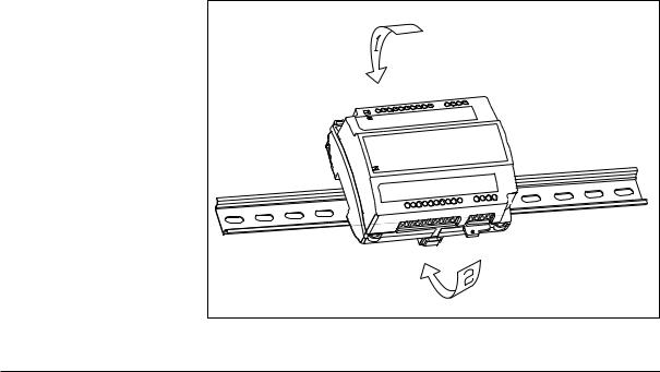
3 Installation
3.1 Mechanical installation
3.1.1 Fitting
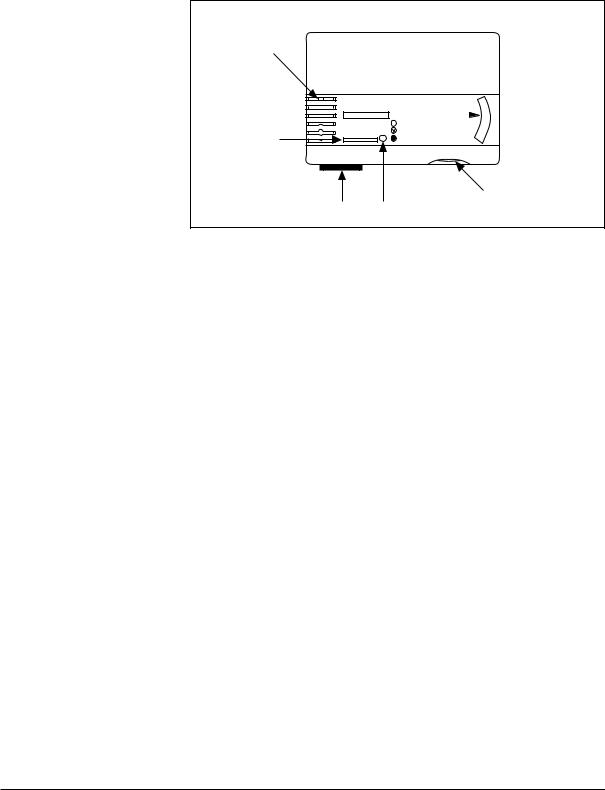
TAC Xenta 102 can either be snapped onto a DIN rail (figure 3.1) or fastened with two screws to a level surface (figure 3.2). On the controllers which controls equipment with 230 V supply, a semi-protection which covers the relay terminals, should be fitted (figure 3.3). A semi-protection is delivered together with these controllers.
To fasten the controller onto a DIN rail:
1.Place the controller on the top of the rail as is shown by arrow 1.
2.Turn the controller downwards until it snaps onto the rail as is indicated by arrow 2.
3.To remove, place a screwdriver in the lock on the bottom of the controller and pull down. Then it is possible to lift the controller diagonally upwards and off the rail.
Figure 3.1 TAC Xenta 102 fastened on a DIN rail
TAC AB, 1999-08-18 |
0-004-7516-1 (GB), 3:1 (10) |
TAC Xenta 102 Handbook |
Installation |
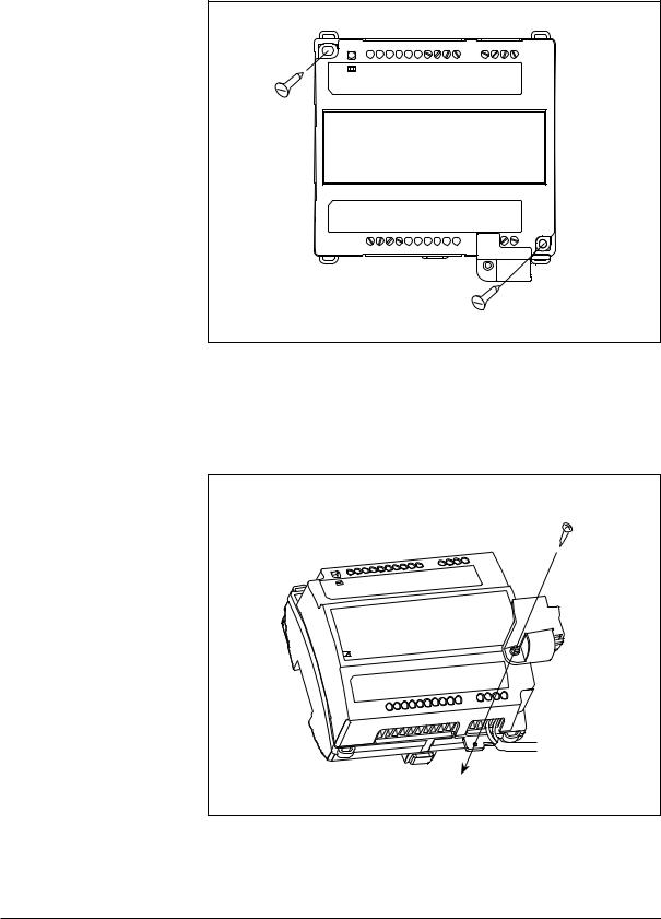
Fastening the controller on a level surface:
Use the two sockets provided for fastening the controller; the maximum screw size is M4 or ST 3,5. The head of the screw should not exceed 7,5 mm in diameter.
Figure 3.2 TAC Xenta 102 fastened on a level surface
To fit the semi-protection:
When the cables are secured, the protection is fitted by means of the enclosed screw.
Figure 3.3 Fitting the semi-protection
3:2 (10), 0-004-7516-1 (GB) |
TAC AB, 1999-08-18 |
TAC Xenta 102 Handbook |
Installation |
3.2 Electrical installation
3.2.1 General
!
Warning! All 230 V supply cables must be installed by authorised electricians.
1.Each controller or group of controllers must be fitted with max. 6 A fuses.
2.Secure the cables to the controller by means of clamps or similar, to limit their mobility.
3.Wire straps or shrinking tubing must prevent loose 230 V cables from getting in contact with ELV cables—supply or signal cables—and vice versa.
4.It must be simple to break the power supply for the controller or for the complete installation.
5.When several Xenta controllers are supplied from a common transformer, it is important that all G’s are connected with each other and that all G0’s are connected with each other. They must not be interchanged. An important exception: G0 on the wall module should not be connected with the other G0’s. Instead it should be connected to the terminal OP on the controller. At the transformer, G0 should be connected to protective earth. This is to get an grounding point for interference diversion.
6.Connect the two M terminals to the wall module to get the specified measuring accuracy for the room temperature.
Safety standard
Transformers supplying the controller must comply to the safety standard EN 60 742 or any other relevant safety standard for ELV, 24 V AC. When equipment with a power supply of its own is connected, e.g. an occupancy sensor, this power supply must also comply with this norm.
Cable lengths
For information on communication cable lengths, see TAC Xenta Network Guide, part number 0-004-7460. For all other cables, maximum length is 30 m and min. area is 0,7 mm2 .
Wall modules ZS 101–ZS 104
It is mainly the wall modules ZS 101–ZS 104 which are intended for use together with TAC Xenta 102. The wall module ZS 105 can also be used, but then the fan switch on this unit is not used. The wiring diagrams on the following pages show how wiring with ZS 104 should be done, as this is the model that has all connections.
TAC AB, 1999-08-18 |
0-004-7516-1 (GB), 3:3 (10) |

TAC Xenta 102 Handbook |
Installation |
Connection terminals
The designation of the connection terminals can be seen in two places on the controller: on the edge of the printed circuit board, and on the label on the front of the controller.
Termin |
Design. |
Function |
Type |
no. |
|
|
|
|
|
|
|
1 |
C1 |
TP/FT-10 communication channel |
- |
2 |
C2 |
TP/FT-10 communication channel |
- |
3*1 |
X3 |
Window contact |
Digital input |
|
|
(Closed contact=closed window) |
|
4 |
M |
Measurement neutral |
- |
5*1 |
X2 |
Occupancy sensor |
Digital input |
6*1 |
Z2 |
Carbon dioxide sensor |
Analogue input |
7 |
M |
Measurement neutral |
- |
8 |
Z1 |
Air flow from VAV-Compact |
Analogue input |
9 |
D1 |
LED on wall module |
Digital output |
10 |
M |
Measurement neutral |
- |
11 |
X1 |
Bypass key on wall module |
Digital input |
12 |
R1 |
Setpoint adjustment on wall |
10 kΩ linear |
|
|
module |
potentiometer |
13 |
M |
Measurement neutral |
- |
14 |
B1 |
Room temperature sensor |
Thermistor input |
15 |
G |
24 V AC (G) |
Input |
16 |
G0 |
24 V AC (G0) |
Input |
17*2 |
OP |
24 V AC supply for TAC Xenta OP |
- |
18 |
G |
24 V AC supply for TAC Xenta OP |
- |
19 |
V1 |
Fan on/off (102-EF and 102-VF) |
|
20 |
G |
24 V AC (G) supply for V1 and V2 |
Output |
21 |
G0 |
24 V AC (G0) |
Output |
22 |
Y2 |
Control signal 0–10 V for heating |
Analogue output |
|
|
valve (only 102-VF) |
|
23 |
M |
Measurement neutral |
- |
24 |
Y1 |
Control signal, air flow controller |
Analogue output |
25 |
— |
Not in use |
- |
26 |
— |
Not in use |
- |
27 |
K1 |
On/off, electric heating coil or |
|
|
|
thermo-actuator (only 102-EF), |
|
|
|
24 V or 230 V AC |
Relay |
28 |
KC1 |
Supply for K1 |
- |
|
|
|
|
*1 See chapter 4 Configuration parameters
*2 Connected alone to G0 on the wall module. Must not be connected to G0 on
the controller.
3:4 (10), 0-004-7516-1 (GB) |
TAC AB, 1999-08-18 |

TAC Xenta 102 Handbook |
Installation |
3.2.2 Wiring of TAC Xenta 102-B
Note! Read section 3.2.1 “General” before you connect the cables according to the wiring diagram in figure 3.4.
LONTALK® |
|
|
|
|
|
|
Junction box |
|
|
|
|
|
|
|
|
||
TP/FT-10 |
|
|
|
|
|
|
|
|
|
|
|
|
|
|
|
|
|
|
|
|
|
|
|
|
|
<![if ! IE]> <![endif]>2001 |
|
|
|
|
|
|
|
|
|
|
|
<![if ! IE]> <![endif]>Window |
<![if ! IE]> <![endif]>contact |
<![if ! IE]> <![endif]>Occupancy |
<![if ! IE]> <![endif]>sensor |
<![if ! IE]> <![endif]>Carbon dioxide |
<![if ! IE]> <![endif]>sensor e.g. GKD V... 24 V AC/DC |
|
Wall module |
|
|
|
|
|
|||
|
|
|
|
|
|
ZS 104 |
|
|
|
||||||||
|
|
GW1 |
GX1 |
GQ1 |
|
|
|
|
|
|
|
||||||
|
|
|
7 |
6 |
5 |
3 |
1 |
2 |
C1 |
C2 |
|||||||
|
|
|
|
|
|
|
(9 |
10) |
|
||||||||
|
|
|
|
|
|
|
|
|
|
|
|
|
|
G |
G0 |
||
|
|
|
|
|
|
|
+ |
– |
|
|
|
|
|
|
|
||
1 |
2 |
3 |
|
4 |
|
5 |
6 |
7 |
8 |
9 |
10 |
11 |
12 |
13 |
14 |
|
|
C1 |
C2 |
X3 |
|
M |
|
X2 |
Z2 |
M |
Z1 |
D1 |
M |
X1 |
R1 |
M |
B1 |
|
|
|
|
|
|
|
|
|
Xenta 102-B |
|
|
|
|
|
|
|
|||
G |
G0 |
OP |
|
G |
|
V1 |
G |
G0 |
|
M |
Y1 |
|
|
|
|
|
|
15 |
16 |
17 |
18 |
|
19 |
20 |
21 |
22 |
23 |
24 |
25 |
26 |
27 |
28 |
|
|
|
|
|
|
|
|
|
|
|
|
1 |
3 |
|
|
|
|
|
|
|
|
|
|
|
|
|
|
|
|
Belimo |
|
|
|
|
|
|
|
|
|
|
|
|
|
|
|
|
|
VAV-Compact |
|
|
|
|
|
|
||
|
|
|
|
|
|
|
|
|
2 |
5 |
|
|
|
|
|
|
|
|
|
|
|
|
|
|
|
Air flow controller |
|
|
|
|
|
|
|||
|
|
|
|
|
|
|
|
with damper |
|
|
|
|
|
|
|
||
24 V AC (G) |
|
|
|
|
|
|
|
|
|
|
|
|
|
|
|
|
|
24 V AC (G0) |
|
|
|
|
|
|
|
|
|
|
|
|
|
|
|
|
|
Figure 3.4 Wiring of TAC Xenta 102-B
TAC AB, 1999-08-18 |
0-004-7516-1 (GB), 3:5 (10) |
 Loading...