


Schneider Electric SW 4048, SW 4024, SW 2524 User Manual
Conext™ SW Inverter/Charger
Conext SW 2524 120/240 (865-2524)
Conext SW 4024 120/240 (865-4024)
Conext SW 4048 120/240 (865-4048)
Installation Guide
975-0639-01-01 Rev F
9-2018
solar.schneider-electric.com
This guide for use by qualified personnel only


Conext SW Inverter/Charger
Conext SW 2524 120/240 (865-2524)
Conext SW 4024 120/240 (865-4024)
Conext SW 4048 120/240 (865-4048)
Installation Guide
solar.schneider-electric.com

Copyright and Contact
Copyright © 2013-2018 Schneider Electric. All Rights Reserved. All trademarks are owned by Schneider Electric
Industries SAS or its affiliated companies.
Exclusion for Documentation
UNLESS SPECIFICALLY AGREED TO IN WRITING, SELLER
(A) MAKES NO WARRANTY AS TO THE ACCURACY, SUFFICIENCY OR SUITABILITY OF ANY TECHNICAL OR OTHER INFORMATION
PROVIDED IN ITS MANUALS OR OTHER DOCUMENTATION;
(B) ASSUMES NO RESPONSIBILITY OR LIABILITY FOR LOSSES, DAMAGES, COSTS OR EXPENSES, WHETHER SPECIAL, DIRECT,
INDIRECT, CONSEQUENTIAL OR INCIDENTAL, WHICH MIGHT ARISE OUT OF THE USE OF SUCH INFORMATION.THE USE OF ANY
SUCH INFORMATION WILL BE ENTIRELY AT THE USER’S RISK; AND
(C) REMINDS YOU THAT IF THIS MANUAL IS IN ANY LANGUAGE OTHER THAN ENGLISH, ALTHOUGH STEPS HAVE BEEN TAKEN TO
MAINTAIN THE ACCURACY OF THE TRANSLATION, THE ACCURACY CANNOT BE GUARANTEED.APPROVED CONTENT IS
CONTAINED WITH THE ENGLISH LANGUAGE VERSION WHICH IS POSTED AT SOLAR.SCHNEIDER-ELECTRIC.COM.
Document Number: 975-0639-01-01 Revision: Rev F Date: 9-2018
Product Part Numbers: 865-2524, 865-4024, 865-4048
Contact Information solar.schneider-electric.com
Please contact your local Schneider Electric Sales Representative or visit our website at:
http://solar.schneider-electric.com/tech-support/
Information About Your System
As soon as you open your product, record the following information and be sure to keep your proof of purchase.
Serial Number
Product Number
Purchased From
Purchase Date
_________________________________
_________________________________
_________________________________
_________________________________

About This Guide
Purpose
The purpose of this Installation Guide is to provide explanations and procedures
for installing the Conext SW Inverter/Charger to a main AC power source such as
an AC generator for off-grid application or AC mains (main power grid) for power
backup application.
Scope
The Guide provides safety and installation guidelines as well as information on
tools and wiring. Complete balance of system installation is not covered. For a
complete balance of system installation using the Conext SW AC Switchgear, DC
Switchgear, and solar charge controllers, consult the Conext SW System Guide.
It does not provide details about particular brands of batteries. You need to
consult individual battery manufacturers for this information.
Audience
Organization
The Guide is intended for use by anyone who plans to install an off-grid/backup
system involving the Conext SW Inverter/Charger. The information in this manual
is intended for qualified personnel. Qualified personnel have training,
knowledge, and experience in:
• Installing electrical equipment and PV power systems (up to 1000 volts).
• Applying all applicable installation codes.
• Analyzing and reducing the hazards involved in performing electrical work.
• Selecting and using Personal Protective Equipment (PPE).
This Guide is organized into:
Chapter 1, “Installation” covers installation instructions.
Chapter 2, “Specifications” covers product specifications.
Chapter 3, “Wiring Diagrams” covers overviews of Conext SW BOS installations
and wiring diagrams.
975-0639-01-01 Rev F iii
This guide for use by qualified personnel only
About This Guide
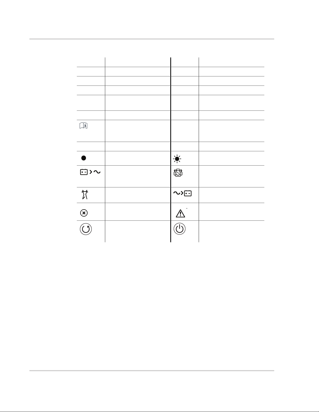
Abbreviations, Acronyms, and Symbols
AC Alternating Current LED Light Emitting Diode
AGS Automatic Generator Start SCP System Control Panel
BOS Balance of System SW Sine Wave
DC Direct Current VAC Volts, Alternating Current
PPE Personal Protective
Equipment
PV Photovoltaic IP20 Ingress protection rating
Reference to see guide
(or manual) for more
information
AC DC
Denotes a steady LED Denotes a flashing LED
Inv Enabled – see
Owner’s Guide for
definition.
AC IN – see Owner’s
Guide for definition.
Fault – see Owner’s Guide
for definition.
Clear Fault | Reset – see
Owner’s Guide for
definition.
VDC Volts, Direct Current
Ground
Gen Support – see
Owner’s Guide for
definition.
Charging – see Owner’s
Guide for definition.
Warning – see Owner’s
Guide for definition.
Inv Enable – see Owner’s
Guide for definition.
Related Information
You can find more information about Schneider Electric as well as its products
and services at solar.schneider-electric.com.
iv 975-0639-01-01 Rev F
This guide for use by qualified personnel only
Important Safety Instructions
READ AND SAVE THESE INSTRUCTIONS - DO NOT DISCARD
This guide contains important safety instructions for the Conext SW Inverter/
Charger that must be followed during operation and troubleshooting. Read and
keep this Installation Guide for future reference.
Read these instructions carefully and look at the equipment to become familiar
with the device before trying to install, operate, service or maintain it. The
following special messages may appear throughout this bulletin or on the
equipment to warn of potential hazards or to call attention to information that
clarifies or simplifies a procedure.
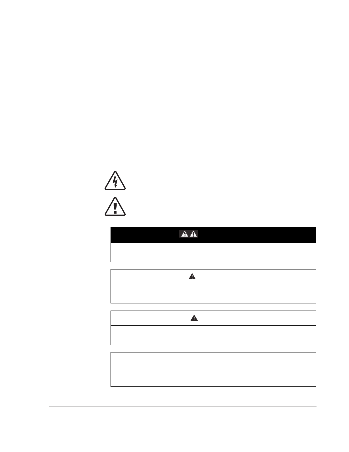
The addition of either symbol to a “Danger” or “Warning” safety label
indicates that an electrical hazard exists which will result in personal
injury if the instructions are not followed.
This is the safety alert symbol. It is used to alert you to potential
personal injury hazards. Obey all safety messages that follow this
symbol to avoid possible injury or death.
DANGER
DANGER indicates an imminently hazardous situation, which, if not avoided,
will result in death or serious injury.
WARNING
WARNING indicates a potentially hazardous situation, which, if not avoided,
can result in death or serious injury.
CAUTION
CAUTION indicates a potentially hazardous situation, which, if not avoided,
can result in moderate or minor injury.
NOTICE
NOTICE indicates a potentially hazardous situation, which, if not avoided, can
result in equipment damage.
975-0639-01-01 Rev F v
This guide for use by qualified personnel only
Safety
Safety Information
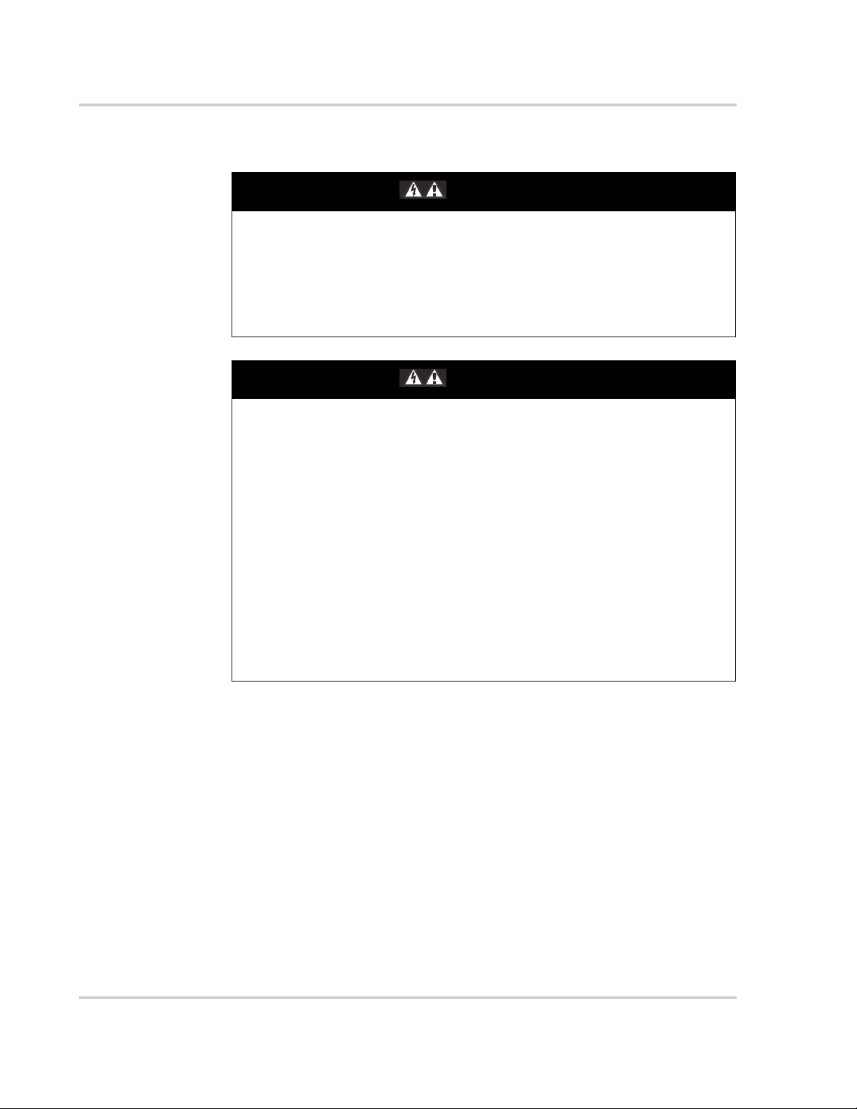
ELECTRICAL SHOCK AND FIRE HAZARD
Installation must be done by qualified personnel to ensure compliance with all
applicable installation and electrical codes and regulations. Instructions for
installing the Conext SW are provided here for use by qualified installers only.
Failure to follow these instructions will result in death or serious injury.
ELECTRICAL SHOCK AND FIRE HAZARD
• Read all instructions, cautionary markings, and all other appropriate
sections of this guide before installing the Conext SW.
• Exercise extreme caution at all times to prevent accidents.
• Do not cover or obstruct ventilation openings.
• Do not mount in a zero-clearance compartment. Overheating may result.
• Do not open nor disassemble the inverter/charger. There are no userserviceable parts inside.
• Do not expose to rain or spray.
• Disconnect and lockout all AC and DC sources before servicing. Servicing
includes maintenance or cleaning or working on any circuits connected to
the inverter/charger. See following note.
Failure to follow these instructions will result in death or serious injury.
DANGER
DANGER
NOTE: Turning off inverter mode using the Inv Enable switch on the front panel,
disabling the inverter and charger functions using the SCP, and putting the unit in
Standby mode will not reduce an electrical shock hazard.
vi 975-0639-01-01 Rev F
This guide for use by qualified personnel only
Safety
DANGER
ELECTRIC SHOCK HAZARD
• For indoor use only. This inverter/charger is designed for off-grid, solar,
backup, and hybrid applications.
• Do not operate the inverter/charger if it has been damaged in any way.
• Do not operate the inverter/charger with damaged or substandard wiring.
Wiring must be done by qualified personnel to ensure compliance with all
applicable installation codes and regulations.
Failure to follow these instructions will result in death or serious injury.
WARNING
EXPLOSION AND FIRE HAZARD
• Charge properly rated lead-acid (GEL, AGM, Flooded, or lead-calcium)
rechargeable batteries because other battery types may explode.
• When using Lithium-Ion batteries, ensure that the battery pack being used
includes a certified Battery Management System (BMS) with safety
controls.
• Do not work in the vicinity of lead-acid batteries. Batteries generate
explosive gases during normal operation. See note #1.
• Do not install and/or operate in compartments containing flammable
materials or in locations that require ignition-protected equipment. See
notes #2 and #3.
Failure to follow these instructions can result in death or serious injury.
NOTES:
1. Follow these instructions and those published by the battery manufacturer
and the manufacturer of any equipment you intend to use in the vicinity of the
battery. Review cautionary markings on these products.
2. This inverter/charger contains components which tend to produce arcs or
sparks.
3. Locations include any space containing gasoline-powered machinery like a
generator, fuel tanks, as well as joints, fittings, or other connections between
components of the fuel system.
CAUTION
FIRE AND BURN HAZARD
Do not cover or obstruct the air intake vent openings and/or install in a zeroclearance compartment.
Failure to follow these instructions can result in moderate or minor injury.
975-0639-01-01 Rev F vii
This guide for use by qualified personnel only
Safety
Precautions When Working With Batteries
IMPORTANT: Battery work and maintenance must be done by qualified
personnel knowledgeable about batteries to ensure compliance with battery
handling and maintenance safety precautions.
DANGER
ELECTRIC SHOCK HAZARD
• Determine if the battery is inadvertently earthed (grounded). If inadvertently
grounded, remove the source from ground.
• Avoid contact with any part of a grounded battery.
• Remove ground during installation and maintenance.
Failure to follow these instructions can result in moderate or minor injury.
WARNING
BURN AND FIRE HAZARD
• Always wear proper, non-absorbent gloves, complete eye protection, and
clothing protection.
• Remove all personal metal items, like rings, bracelets, and watches when
working with batteries. See CAUTION below.
• Never smoke or allow a spark or flame near batteries.
• Batteries can produce a short circuit current high enough to weld a ring or
metal bracelet or the like to the battery terminal, causing a severe burn.
Failure to follow these instructions can result in death or serious injury.
CAUTION
CHEMICAL, BURN, AND EXPLOSION HAZARD
• Never allow battery acid to drip when reading specific gravity or filling
battery.
• Make sure the area around the battery is well ventilated.
• Make sure the voltage of the batteries matches the output voltage of the
inverter/charger.
Failure to follow these instructions can result in moderate or minor injury.
viii 975-0639-01-01 Rev F
This guide for use by qualified personnel only
Safety
WARNING
LI
LIMITATIONS ON USE
Do not use in connection with life support systems or other medical
equipment.
Failure to follow these instructions can result in death or serious injury.
NOTICE
RISK OF INVERTER/CHARGER DAMAGE
• Never place the Conext SW Inverter/Charger unit directly above batteries;
gases from a battery will corrode and damage the inverter/charger.
• Never place the Conext SW Inverter/Charger unit in the same compartment
as batteries due to an explosive hazard.
Failure to follow these instructions can result in damage to equipment.
NOTICE
RISK OF BATTERY DAMAGE
Study and follow all of the battery manufacturer's specific precautions, such
as removing or not removing cell caps while charging, whether equalization is
acceptable for your battery, and recommended rates of charge.
Failure to follow these instructions can result in damage to equipment.
975-0639-01-01 Rev F ix
This guide for use by qualified personnel only

Safety
FCC Information to the User
This equipment has been tested and found to comply with the limits for a Class B
digital device, pursuant to part 15 of the FCC Rules. These limits are designed to
provide reasonable protection against harmful interference in a residential
installation. This equipment generates, uses, and can radiate radio frequency
energy and, if not installed and used in accordance with the instructions, may
cause harmful interference to radio communications.
However, there is no guarantee that interference will not occur in a particular
installation. If this equipment does cause harmful interference to radio or
television reception, which can be determined by turning the equipment off and
on, the user is encouraged to try to correct the interference by one or more of the
following measures:
• Reorient or relocate the receiving antenna.
• Increase the separation between the equipment and receiver.
• Connect the equipment into an outlet on a circuit different from that to which
the receiver is connected.
• Consult the dealer or an experienced radio/TV technician for help.
x 975-0639-01-01 Rev F
This guide for use by qualified personnel only

Contents
Important Safety Instructions
Safety Information ----------------------------------------------------------vi
Precautions When Working With Batteries ----------------------------------------viii
FCC Information to the User ---------------------------------------------------x
1 Installation
Materials List ------------------------------------------------------------1–2
Conext SW Front and Side Panels ------------------------------------------1–3
Front Panel Buttons and Status LEDs -------------------------------------1–4
Conext SW AC/DC/Ports Side Panel --------------------------------------1–5
Conext SW Supplied Accessories ------------------------------------------1–6
Conext SW Required Accessory --------------------------------------------1–7
Installation Information -----------------------------------------------------1–8
Before You Begin the Installation -------------------------------------------1–8
Installation Codes ------------------------------------------------------1–8
Xanbus Network System ----------------------------------------------------1–9
Xanbus System --------------------------------------------------------1–9
Xanbus-enabled Products and Other Accessories ------------------------------1–10
Installation Planning ------------------------------------------------------ 1–11
Planning Preparations -------------------------------------------------- 1–11
Components of the Inverter Power System ----------------------------------- 1–11
AC, DC, and Network Components -------------------------------------1–12
Unpacking and Inspecting the Conext SW Inverter/Charger -----------------------1–16
Installation Tools and Materials ------------------------------------------- 1–17
Tools ----------------------------------------------------------- 1–17
Materials -------------------------------------------------------- 1–17
Inverter/Charger Installation------------------------------------------------- 1–18
Overview -----------------------------------------------------------1–18
Step 1: Choosing a Location for the Inverter/Charger ---------------------------- 1–19
Step 2: Mounting the Inverter/Charger --------------------------------------1–20
Step 3: Connecting the AC Input and AC Output Wires -------------------------- 1–22
General AC Wiring Considerations -------------------------------------- 1–22
AC System Bonding --------------------------------------------------- 1–23
Step 4: Installing the DC Switchgear and Connecting the DC Cables ---------------- 1–25
DC Connection Precautions ------------------------------------------- 1–25
Installing the DC Switchgear next to Conext SW Inverter/Charger ---------------- 1–26
Connecting the DC Cables to the DC Switchgear --------------------------- 1–27
Step 5: Connecting the BTS and Xanbus-enabled Components -------------------- 1–29
Step 6: Performing Checks Prior to Initial Start-Up ------------------------------ 1–31
Step 7: Testing Your Installation ------------------------------------------- 1–31
Testing in Invert Mode ----------------------------------------------- 1–32
975-0639-01-01 Rev F xi
This guide for use by qualified personnel only

Contents
Testing in Charge Mode and AC Bypass Mode ----------------------------- 1–32
Installation Complete ----------------------------------------------- 1–33
Multiple Unit Configuration ------------------------------------------------- 1–34
DC Connections for Multiple Unit Configuration -------------------------------- 1–36
Configuring the System for Multiple Unit Operation ----------------------------- 1–37
Search Mode Operation in Multiple Unit Configuration --------------------------- 1–38
Wiring Schematic ----------------------------------------------------- 1–38
Battery Information ------------------------------------------------------- 1–39
Battery Bank Sizing --------------------------------------------------- 1–39
Estimating Battery Requirements ------------------------------------------ 1–40
Calculating Battery Size --------------------------------------------- 1–40
Battery Banks ----------------------------------------------------- 1–41
Battery Bank Sizing Worksheet ---------------------------------------- 1–41
Restrictions on Motor Size ----------------------------------------------- 1–42
Battery Cabling and Hook-up Configurations --------------------------------- 1–43
Battery Parallel Connection ------------------------------------------- 1–43
Battery Series Connection -------------------------------------------- 1–44
Battery Series-Parallel Connections ------------------------------------- 1–44
2 Specifications
Inverter Specifications ----------------------------------------------------- 2–2
Charger Specifications ----------------------------------------------------- 2–3
AC Transfer Specifications -------------------------------------------------- 2–4
Physical Specifications ----------------------------------------------------- 2–5
Environmental Specifications ------------------------------------------------ 2–5
Regulatory-------------------------------------------------------------- 2–6
3 Wiring Diagrams
Single-Inverter System (Off-Grid/Power Backup)----------------------------------- 3–3
Single-Inverter System Renewable Energy (Solar)---------------------------------- 3–5
xii 975-0639-01-01 Rev F
This guide for use by qualified personnel only

Figures
Figure 1-1 Materials List------------------------------------------------------1–2
Figure 1-2 Conext SW Front and Side Panels---------------------------------------1–3
Figure 1-3 Front Panel Buttons and Status LEDs ------------------------------------1–4
Figure 1-4 AC and DC Terminals, Network and Communication Ports Panel-----------------1–5
Figure 1-5 Supplied Accessories -----------------------------------------------1–6
Figure 1-6 DC Switchgear ----------------------------------------------------1–7
Figure 1-7 Xanbus System Diagram Example -------------------------------------- 1–9
Figure 1-8 AC, DC, and Network Components ------------------------------------- 1–12
Figure 1-9 AC, DC, and Network Components ------------------------------------- 1–13
Figure 1-10 Conext SW Mounting Instructions --------------------------------------1–21
Figure 1-11 Conext SW AC INPUT and OUTPUT Connections--------------------------- 1–24
Figure 1-12 Installing the DC Switchgear------------------------------------------1–26
Figure 1-13 Conext SW DC Connections ------------------------------------------1–28
Figure 1-14 Conext SW BTS and Xanbus Connections -------------------------------- 1–30
Figure 1-15 Conext SW Front Panel---------------------------------------------- 1–32
Figure 1-16 Multiple (Dual) Unit Configuration Using Two Conext SW Units ----------------- 1–35
Figure 1-17 Connecting Battery Cables-------------------------------------------1–36
Figure 1-18 Multi Menu Screen ------------------------------------------------- 1–37
Figure 1-19 Batteries Connected in Parallel ----------------------------------------1–43
Figure 1-20 Batteries Connected in Series-----------------------------------------1–44
Figure 1-21 Batteries in Series-Parallel Connections----------------------------------1–44
Figure 2-1 Output Power versus Temperature Derating Graph --------------------------2–5
Figure 3-1 Single-Inverter System (Off-Grid/Backup) Overview --------------------------3–3
Figure 3-2 Single-Inverter System (Off-Grid/Backup) Wiring ----------------------------3–4
Figure 3-3 Single-Inverter System Renewable Energy (Solar) Overview --------------------3–5
Figure 3-4 Single-Inverter System Renewable Energy (Solar) Wiring ----------------------3–6
975-0639-01-01 Rev F xiii
This guide for use by qualified personnel only

xiv

Tables
Table 1-1 AC Wire Size In and Out of the Inverter/Charger---------------------------- 1–14
Table 1-2 Recommended Battery Cable Sizes ------------------------------------ 1–15
Table 1-3 Recommended Fuse and Breaker Sizes --------------------------------- 1–15
Table 1-4 Battery Sizing Example --------------------------------------------- 1–41
Table 1-5 Battery Sizing Worksheet -------------------------------------------- 1–42
975-0639-01-01 Rev F xv
This guide for use by qualified personnel only

xvi

1 Installation
The following topics will be covered in this
chapter.
• Materials List
• Installation Information
• Xanbus Network System
• Installation Planning
• Inverter/Charger Installation
• Multiple Unit Configuration
• Battery Information
• Wiring Diagrams
975-0639-01-01 Rev F 1–1
This guide for use by qualified personnel only
Installation
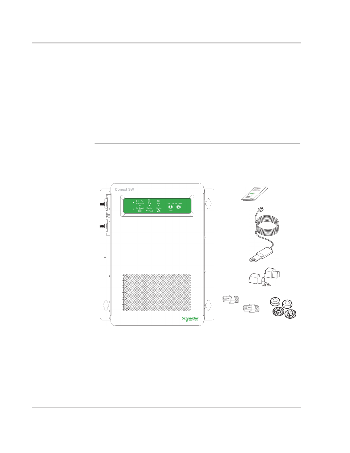
Materials List
The Conext SW ships with the following items:
• One Conext SW unit
• One set of owner’s and installation guides
• One Battery Temperature Sensor (BTS)
• Two Xanbus network terminators
• Two sets of 5/16
• Two DC terminal covers (red and black) with two sets of #6-32 screws
• One Installation bracket with one set of M6 nuts for mounting (not shown)
NOTE: If any of the items are missing, contact your dealer and/or sales
representative. For code-compliant installations in Canada and USA, the DC
Switchgear accessory is required. See “Conext SW DC Switchgear*” on
page 1–10.
"-8
nuts and washers for the DC terminals,
Figure 1-1 Materials List
1–2 975-0639-01-01 Rev F
This guide for use by qualified personnel only
Conext SW Front and Side Panels
2
TOP TOP
3
Materials List
1
77
4
5
Figure 1-2 Conext SW Front and Side Panels
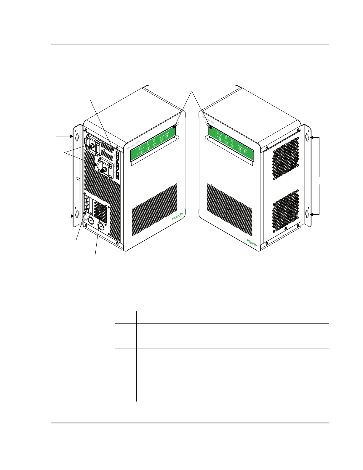
Before you begin to operate the Conext SW after installation, review the front
panel features shown in Figure 1-3 and described in the next table. A detailed
view of the lights and buttons on the front panel is also shown.
Item Description
1 Front Panel contains the Inv Enable and Clear Fault | Reset buttons, as
well as various LEDs (status indicator lights). See “Front Panel Buttons
and Status LEDs” on page 1–4.
2 Network and communications ports. See “AC and DC Terminals,
Network and Communication Ports Panel” on page 1–5.
3 DC battery terminals. See “AC and DC Terminals, Network and
Communication Ports Panel” on page 1–5.
4 AC Ground terminals. See “AC and DC Terminals, Network and
Communication Ports Panel” on page 1–5.
6
975-0639-01-01 Rev F 1–3
This guide for use by qualified personnel only
Installation
Item Description
5 AC line terminals. See “AC and DC Terminals, Network and
Communication Ports Panel” on page 1–5.
6 Two variable-speed cooling fans maintain a cool internal temperature
of critical components. The two fans control airflow through the
transformer and power compartments of the unit. Ensure at least
10" (254 mm) of clearance for proper ventilation.
7 Mounting holes for permanent installation. See “Step 2: Mounting the
Inverter/Charger” on page 1–20.
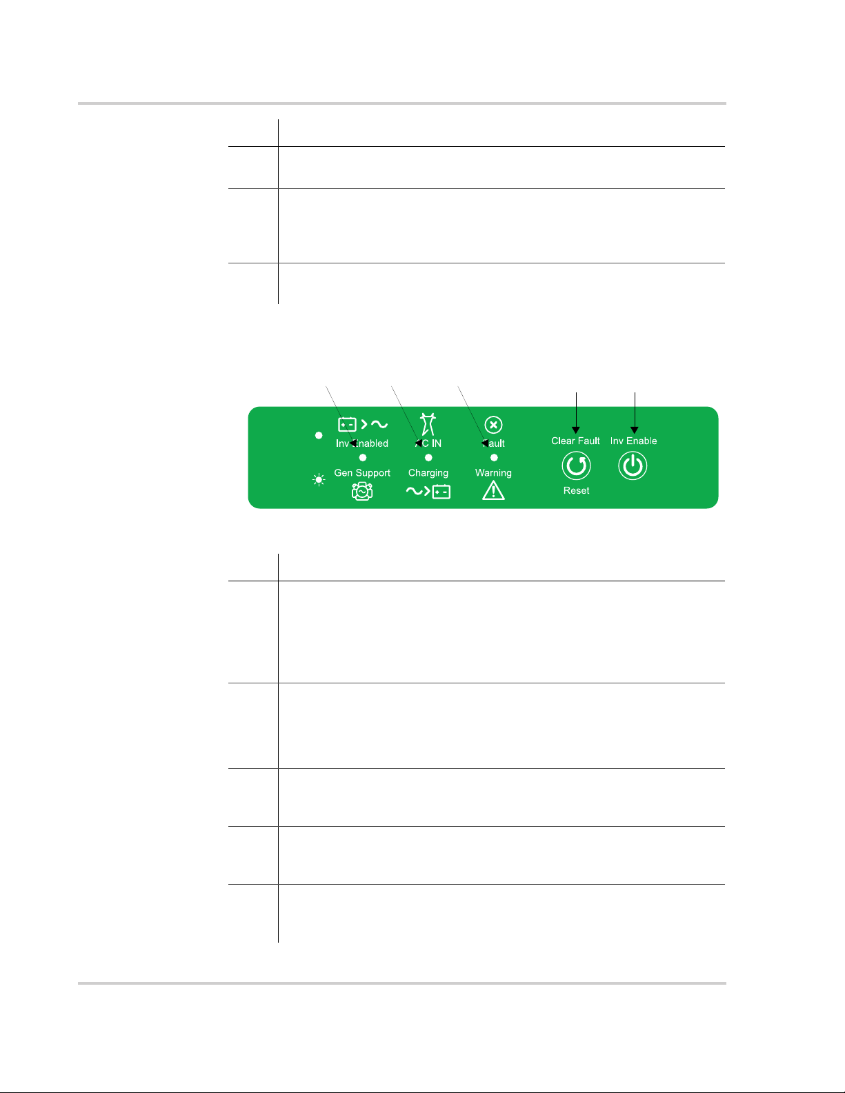
Front Panel Buttons and Status LEDs
54321
Figure 1-3 Front Panel Buttons and Status LEDs
Item Description
1 The Inv Enabled LED illuminates steadily when invert mode is enabled.
If AC is present and invert mode is enabled, this LED remains
illuminated even though AC power is being passed through.
Gen Support LED flashes intermittently when the inverter is in AC
support mode and load shaving mode.
2 When AC is present and qualified, the AC IN LED will illuminate steadily
indicating also that AC is passing through.
Charging LED flashes intermittently when the Conext SW is in charge
mode and is producing DC output to charge your batteries.
3 Fault | Warning LED illuminates steadily if a fault is detected (a fault
detection condition) and flashes intermittently when a warning
condition is active.
4 Clear Fault | Reset button is used to clear any detected faults if
pressed momentarily. If held down for more than three seconds, the
unit will reset (reboot) itself.
5 Inv Enable button is used to enable and disable inverter mode.
“Enabled” is different from the inverter being “on”. When enabled, the
inverter can be on or off. When disabled, the inverter is always off.
1–4 975-0639-01-01 Rev F
This guide for use by qualified personnel only
Conext SW AC/DC/Ports Side Panel
1
2
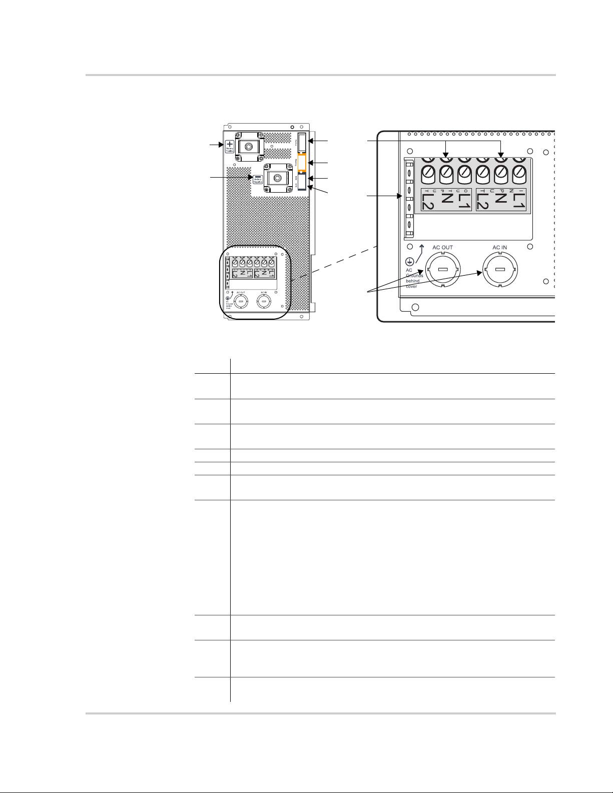
Figure 1-4 AC and DC Terminals, Network and Communication Ports Panel
Materials List
7
3
4
5
6
8
9
ab
Item Description
1 Battery Positive (+) (red) DC terminal connects to the positive bus bar
of the DC Switchgear.
2 Battery Negative (–) (black) DC terminal connects to the negative bus
bar of the DC Switchgear.
3 XANBUS interface ports are used to connect Xanbus-enabled devices
including the optional SCP and AGS.
4 STACKING port. Feature not available in this model.
5 Remote (REM) port provides connection for the on/off remote switch.
6 Battery temperature sensor (BTS) port provides connection for the
battery temperature sensor (supplied).
7 AC input/output lines wiring compartment access panel without the
compartment cover.
(a) AC Input terminal block is a screw-type terminal block for attaching
AC input wires. The terminals are labeled INPUT N for Neutral and
INPUT L1 and L2 for split-phase lines 1 and 2 respectively.
(b) AC Output terminal block is a screw-type terminal block for
attaching AC output wires. The terminals are labeled OUTPUT N for
Neutral and OUTPUT L1 and L2 for split-phase lines 1 and 2
respectively.
8 All Ground terminals are along the tab (as shown) of the AC wiring
compartment access panel opening.
9 AC knockouts (3/4" and 1") provide access for AC cables (both input
and output wiring). Detach the knockout covers and install strain-relief
clamps available in hardware and electrical stores.
Not
shown
AC wiring compartment cover that is taken out during wiring and put
back in when wiring has been completed.
975-0639-01-01 Rev F 1–5
This guide for use by qualified personnel only
 Loading...