

Applications
For two-position operation of dampers or valves in
heating, ventilating and air-conditioning systems and
similar applications where return to normal position is
not required.
These unidirectional actuators (clockwise rotation)
require a three-wire control circuit; SPDT snap-acting
switch or its equivalent such as a thermostat, pressure
switch or relay. A built-in cam operated, snap-acting,
adjustable SPDT auxiliary switch is standard. It is
factory set to make at mid-stroke. One contact closes
at end of stroke; other contact closes at end of next
stroke.
MC-351, 421, 431, MC-4311
Three-Wire, Two Position Actuators
General Instructions
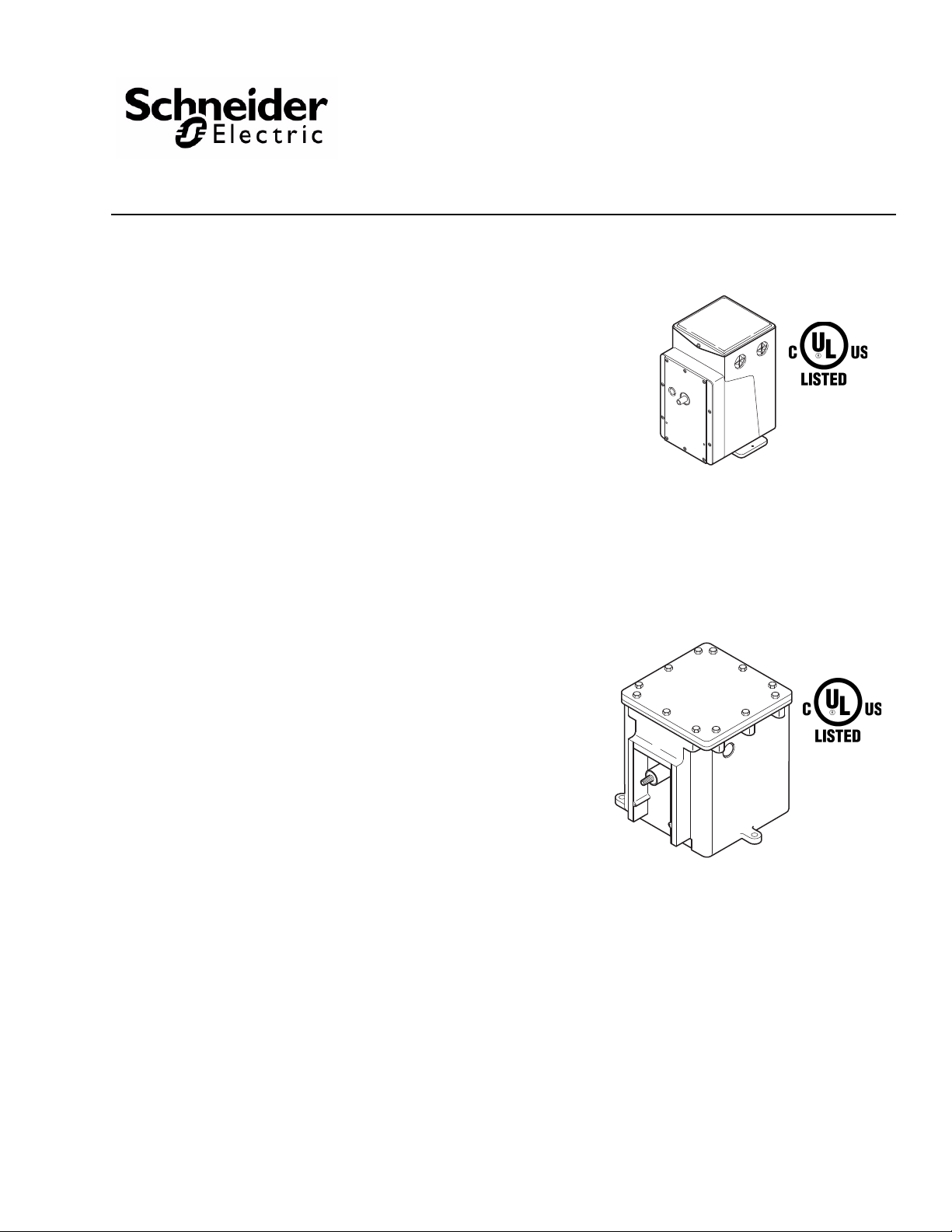
MC-xxx
(Standard Actuator)
Features
• 24, 120, and 240 Vac models
• Equipped with SPDT auxiliary switch
• Actuator has a rugged die cast aluminum housing
with two 1/2” conduit openings
• Hazardous location actuator housing has two 3/4"
pipe taped openings for rigid metal conduit
connection
• Oil immersed gear train
• Requires a three wire control circuit SPDT
snap-acting or equivalent
Options
Available 24, 120, 208, 240 Vac; 50 or 60 Hz. 50 Hz
specify MC5-xxx. For hazardous locations, specify
MC6-xxx (60 Hz), MC7-xxx (50 Hz). Actuators factory
assembled, UL Listed, cUL Listed.
MC6-3xx, MC6-4xx, MC7-4xx,
(Hazardous Location Actuator)
Applicable Literature
• AV-390 Series, Valve Linkage for Gear Train
Actuators, General Instructions, F-24376
• Electric/Electronic Products Catalog, F-27382
Printed in U.S.A. 6/12 © Copyright 2012 Schneider Electric All Rights Reserved. F-08366-15
• Apparatus for Hazardous Locations EN-56-2
F-18451
• AV-29x Series Hazardous Location Valve Linkage
for Geartrain Actuators General Instructions
F-27441

SPECIFICATIONS
Control Circuit: Three Wire SPDT snap-acting switch or equivalent.
Shaft Rotation: Unidirectional clockwise 180° when power is applied.
Auxiliary Switch: Adjustable SPDT is standard. Factory set to make (or break) at mid stroke.
Running, 5.8A at 120 Vac, 2.9 at 240 Vac
Locked Rotor: 34.8 at 120 Vac, 17.4 at 240 Vac
Non-inductive, 12A at 120 Vac, 6 at 240 Vac.
Environment:
Ambient temperature limits: Shipping and storage -40 to 136 °F (-40 to 58 °C)
Operating -40 to 136 °F (-40 to 58 °C).
Humidity: 5 to 95% RH, non-co ndensing.
Locations: NEMA 1. Optional NEMA 4 with AM-363 gasket, or hazardous service locations
N.E.C., Class 1, Groups C and D, and Class 2, Groups E, F, and G.
Connections: Coded screw terminals.
Options: Hazardous locations specify MC6-351, 421, or 431 (60 hz), MC7-4311 (50 hz).
Agency Listing: UL File #E9429 standard models.
UL File #29291 Hazardous location models. Temperature code T6 for hazardous housing.
T able-1 Model Chart.
Input
No Load
Timing
(Sec./180
×)
Rated Torque
Lb.-in. (N-m)
d
Part No.
Hazardous
Location
MC7-4311
a b
Volts Hz Watts VA Rating
d
240 50 50 96 36 220 (25) 122 (11) 157 (15)
Part No.
Standard
Service
MC-351 MC6-351 24 60 28 53 70 220 (25) 122 (11) 157 (15)
MC-421 MC6-421 120 60 50 96 20 175 (20) 97 (9) 125 (12)
MC-431 MC6-431 120 60 50 96 30 220 (25) 122 (11) 157 (25)
MC-4311 — 240 60 50 96 30 220 (25) 122 (11) 157 (15)
MC5-4311
a
Class 1, Groups C & D, and Class 2, Groups E, F, and G hazardous locations; ref er to EN-56 -2, F-18451. Hazardou s locatio n valve actuato rs can also be used
for hazardous location damper applications.
b
Models for hazardous locations are only available as fa ctory-built enclosure/act uator asse mblies. See st a ndard actuat or p art n umber wiring di agrams f or wiring
terminations.
c
Damper ratings are nominal and based on standard (not low leakage) dampers at 1" (25.4 mm) W.C. static pressure and 2000 FPM (10 ml/S) velocity.
d
Not cUL approved.
Nominal Damper
Sq. Ft. (m2)
Parallel
Blade
Opposed
c
Area
Blade
ACCESSORIES
Damper Linkage Accessories (See Figure-1)
AM-111 Crank arm for 5/16" diameter damper shaft
AM-112 Crank arm for 3/8" diameter damper shaft
AM-113 Crank arm for actuator or 1/2" diameter damper shaft
AM-115 Crank arm for 7/16" diameter damper shaft
AM-116 Splined crank arm for actuator
AM-122 Linkage connector straight type
AM-123 Damper clip
AM-125 5/16" diameter x 20" damper rod
AM-125-048 5/16" diameter x 48" damper rod
AM-132 Ball joint connector
AM-161 Damper linkage kit
AM-161-1 Damper linkage kit
AM-301 90 degree mounting bracket
Valve Linkage Accessories (See Figure-4)
AV-330 Valve linkage for 2-1/2" & 3" VB-9323
AV-352 Valve linkage for 2-1/2" to 6" VB-9213 or VB-9313 valve bodies and 4" to 6" for VB-9323
AV-393 Valve linkage for 1/2" to 2" VB-7xxx and 1/2" to 1-1/4" VB-92x3 or VB-93x3
AV-394 Valve linkage for 1-1/2" & 2" VB-92x3 or VB-93x3 (discontinued)
AV-396 Valve linkage for 2-1/2" to 4" VB-9213 or VB-9313
Valve Linkage Hazardous Location Accessories (See Figure-5)
AV-293 Valve linkage for 1/2" to 2" VB-7xxx series for hazardous locations
AV-296 Valve linkage for 2-1/2" and 3" VB-9xxx (bronze) series for hazardous location
2 © Copyright 2012 Schneider Electric All Rights Reserved. F-08366-15

Miscellaneous Actuator Accessories
Standard models only.
AM-321 Two step switch kit
AM-341 Four step switch kit
AM-363 NEMA 4 rated gasket kit
TYPICAL APPLICATION (Wiring Diagram)
Make all electrical connections in compliance with the job wiring diagram and the national and
local electric codes. Typical connections are shown in (Figure-2).
Figure-1 Damper Linkage Accessories.
Figure-2 External Wiring for Heating Application.
PRE-INSTALLATION
The MC actuators are shipped without mounting hardware or linkage. In damper applications,
crank arms (AM-113), connectors (AM-122 or AM-132), link rods (AM-125) and mounting
brackets (AM-301) will be required. In valve applications, a valve body and AV type linkage will
be required.
Before installing the actuator, check for bent or broken parts or oil leaks. Actuators may be
connected to power supply to check operation prior to installation.
F-08366-15 © Copyright 2012 Schneider Electric All Rights Reserved. 3

INSTALLATION
Requirements Preferred mounting for the actuator is in the upright position, but other positions are acceptable.
Adjustable speed units should never be mounted upside down or with the output shaft pointing
upward. Allow six inches clearance above the actuator wiring compartment. If an AM type
mounting bracket is not used, the base of the actuator may be used as a template for marking
mounting holes.
Procedure Actuator may be used in damper and valve control applications. Figure-3 illustrates linkage
operating an arm through a 90° arc. To fasten damper linkage proceed as follows.
Figure-3 180° Actuator Rotation Driving a Damper
Rotation of 90°.
Damper Installation
1. Fasten linkage connector at end of damper crank arm.
2. Fasten linkage connector at punch mark on actuator crank arm (about .707 of the radius).
3. Move damper to normal position and clamp connecting link to connectors.
4. Check adjustment for proper operation by running actuator and driven shaft between limits
of travel.
Caution: If crank arm does no t provide proper travel, reset connecting link in linkage
connector. Never attempt to turn the actuator shaft with a wrench or a crank. This may damage
the gears.
Valve Installation Install all valves with pressure under seat. Refer to flow arrow on body or piping information on
valve body tag. Three way mixing valves should be installed with two inlets and one outlet. Three
way diverting valves should be installed with one inlet and two outlets.
To assemble an actuator to a valve, refer to detailed instructions on AV-3xx General Instruction
Sheet, F-19068 or AV-29x Series Hazardous Location Valve Linkage for Geartrain Actuators
General Instructions, F-27441.
4 © Copyright 2012 Schneider Electric All Rights Reserved. F-08366-15
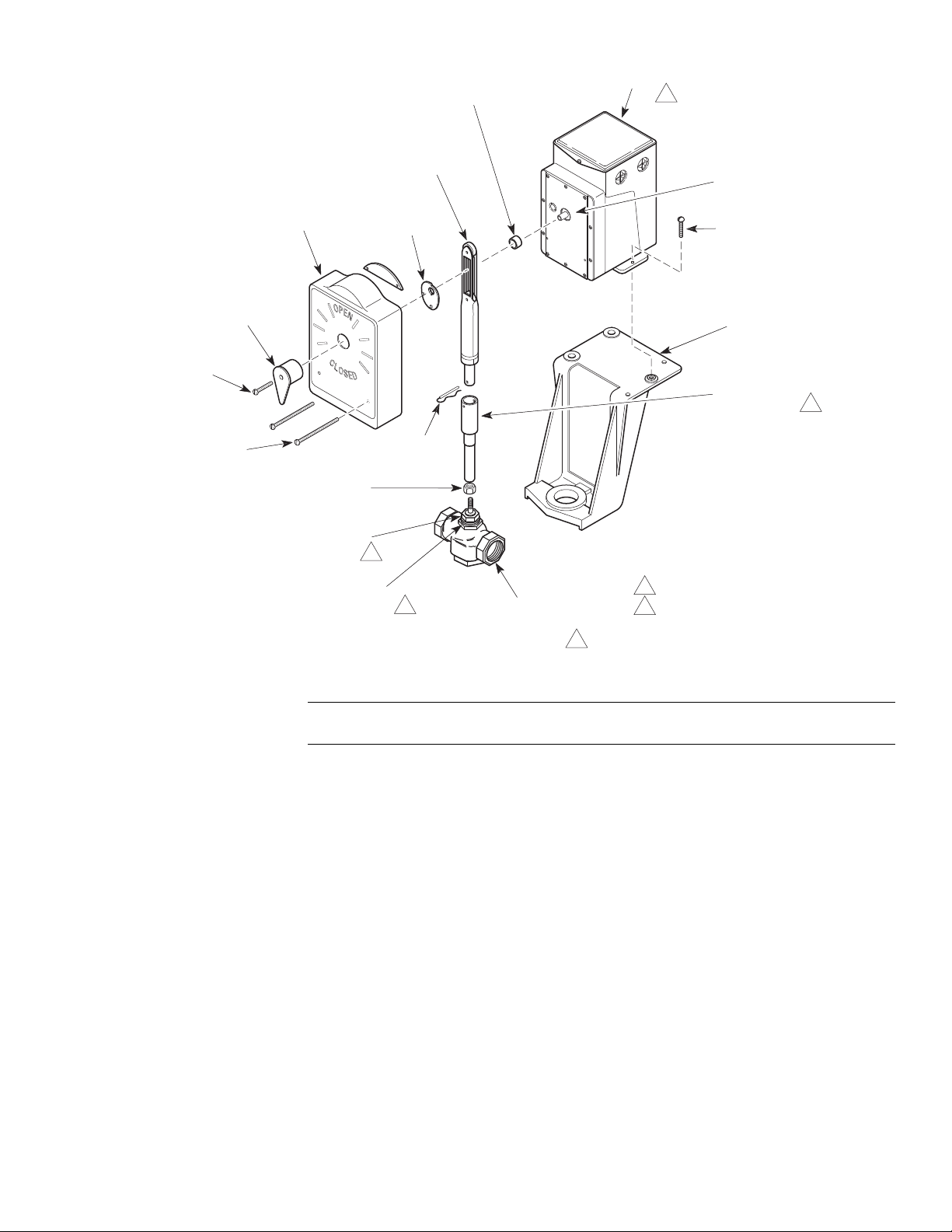
Figure-4 Co mponents for Valve Installation of Standard Actuator.
Indicator Screw
Front Cover
Nylon Bushing
Actuator
Mounting Screws (3)
Mounting Bracket
Valve Body
(VB-7XXX Shown)
Plunger Assembly
Connecting Pin
Stem Extension
Stem Locknut
Packing Nut
Mounting Nut
Cover Screws (2)
Indicator
Plunger Cam
1
1
1
1
"C" Ring
1 Not included in AV Kits.
2 Used with 1/2" through 2" valve bodies.
2
Note: See AV-390 Series, Valve Linkage for Gear Train Actuators, General
Instructions, F-24376 for detailed instructions when used as a valve actuator.
F-08366-15 © Copyright 2012 Schneider Electric All Rights Reserved. 5

Indicator Screw
Front Cover
Nylon Bushing
Mxx-xxx Hazardous Location Actuator
Mounting Screws (3)
Mounting Bracket
Valve Body
Plunger Assembly
Connecting Pin
Stem Extension
Stem Locknut
Packing Nut
Mounting Nut
Cover Screws (2)
Indicator
Plunger Cam
1
1
1
1 Not included in AV kits.
1
Figure-5 Co mponents for Valve Installation 1/2” to 2” VB-7xxx and VB-9xxx-xxx-4-xx 2-1/2" and 3" Globe Valves
for Hazardous Location Actuators.
Note: See AV-29x Valve Linkage for Hazardous Location Gear Train Actuators
General Instructions, F-27441 for detailed instructions when used as a valve actuator.
6 © Copyright 2012 Schneider Electric All Rights Reserved. F-08366-15
WIRING
For control and power wiring on low voltage actuators (H, G, R, B AND C terminals), use No. 14
wire on runs under 140 feet and No. 12 wire on longer runs. On line voltage units (L1, L2, R, B,
and C terminals), use No. 14 wire on runs up to 1300 feet.
Class I circuits must be used for connections to the control and power terminals (L1, L2, R, B,
and C terminals) on line voltage actuators. Class II circuits may be used for connections to the
control and power terminals (H, G, R, B, and C terminals) on 24 Vac actuators. Connections to
the auxiliary switch terminals (R1, B1, and C1) may be per Class II circuits except when the
switch is used on line voltage applications in which case Class I circuit must be used. When
powering actuators from a common transformer, the G terminals must all connect to the same
side to prevent transformer damage.
Hazardous Location Models
Make all electrical connections to the assembly in accordance with the job wiring diagram, the
National Electric Code Article 500, and in compliance with the local electrical codes.
Two 3/ 4" pipe tapped openings are provided in the housing for rigid conduit connections. It is
recommended to insert a chase nipple from inside of the housing to prevent threads from cutting
or damaging wiring.
When wiring, take care to lay all leads in the wiring channel located just under the housing cover
to protect the leads from any sharp edges which may be in the vicinity.
The housing and the edge of the cover are stamped with the letter "O." When replacing the cover,
the letters must be aligned with each other.
Warning: The cover-to-housing orientation must be maintained in order to preserve the
integrity of the seal. Failure to observe this warning can result in injury or death.
1. Remove twelve cover screws and cover. Place cover, machined surface up, in a protected
location to avoid damage to machined surfaces.
2. Make all wiring connections to actuator taking care to lay all leads in the wiring channel
provided.
3. Before enclosing the actuator, wipe machined surfaces of housing clean with a lint free cloth
and apply one of the UL approved compounds. See Note below.
Warning: Failure to observe these warnings can result in injury or death.
• Do not scrape, scratch, or use abrasives on the machined surfaces.
• Ensure the surfaces are clean.
• Use only the approved compounds listed below.
4. Secure cover tight against the enclosure in the same position before removal with the twelve
screws provided.
Note: Underwriters Laboratories has sanctioned the use of the following compounds on
hazardous location ground joints: Crouse-Hinds type OSL lubricant, Crouse-Hinds type STL
lubricant, or "No-OXID" oil, grade "D."
Two 1/ 2
Refer to Figure-6 for terminal locations.
" conduit knockouts are provided on the actuator case.
F-08366-15 © Copyright 2012 Schneider Electric All Rights Reserved. 7

CHECKOUT
After the entire system has been installed, the following checks for proper operation must be
made.
1. Be sure that the system power is connected, and on.
2. Turn thermostat to call for cool. Actuator should rotate clockw ise from 0° t o 180°, tur ning of f
the heating media. (View actuator from output shaft end (front).)
3. Turn thermostat to call for heat. Actuator should rotate clockwise from 180° to 360° (also 0°),
and turn on heating media.
4. If the room temperature varies excessively, see System Repair.
Actuator Checkout Turn power off and connect terminals as follows:
1. Connect terminal C to B and actuator should run clockwise (when energized) to end of travel
(usually 180°).
2. Connect terminal C to R and actuator should run clockwise (when energized) from 180° to
360° (0°).
RUN/ADJUST
Theory of
Operation
Unidirectional
Three-Wire,
Two-Position
Actuators
The motor, gear-train assembly with limit switches to stop the movement (usually at the end of
180° CW travel) is built in two types. The damper actuator output shaft gives rotary motion. The
valve actuator has a cam-operated plunger which transforms rotary motion to linear motion to
operate the valve stem. Three-wire actuators require a SPDT switching action in the controller.
“R” contact of the thermostat is made on a call for heat; “B” contact is made on a call for less heat;
“C” terminal is common. “R” of the actuator (assume on valve) is a starting switch that starts to
open the valve; “B” starts to close the valve; and “C” is the limit switch. Auxiliary cam-operated
switches are available for the operation of additional valves, actuators, relays, etc.
Figure-6 Internal Wiring Diagram and Cam Chart.
8 © Copyright 2012 Schneider Electric All Rights Reserved. F-08366-15

Auxiliary Switch Adjustment
The adjustable built-in SPDT auxiliary switch is actuated by the cam nearest to the back of the
actuator. Although it can be adjusted to operate at any point in the actuator rotation, it is factory
set to operate at approximately mid-stroke. This operating point may be changed by inserting a
screwdriver through the opening in the top plate directly behind the terminal block, and engaging
the screwdriver with the gear-like plastic disc. Turning the disc clockwise causes the switch to
operate nearer the counterclockwise end of actuator travel. Each click of the switch actuating
cam represents approximately 3 angular degrees change in operating point.
Figure-7 Cut-a-way of Actuator.
REPAIR
None. Replace an inoperable actuator with a functional unit.
F-08366-15 © Copyright 2012 Schneider Electric All Rights Reserved. 9

DIMENSIONAL DATA
Allow 12” (300 mm) minimum service clearance above the housing top.
O
P
E
N
C
L
O
S
E
D
8-1/4 (209)
4-1/8 (105)
4-1/2
(114)
7
(178)
9
(228)
Coupling Line
for Actuator
1/4
(6)
Dimensions shown
are in inches (mm).
4-1/4 (108)
Coupling Line
for Valve Body
5-7/16
(139)
7-7/8 (200)
Figure-8 Standard Actuator Dimensions.
Hazardous Location
Shown with valve linkage components. Mounting bracket, open/close cover, pointer, and plunger
are not included for damper applications.
10 © Copyright 2012 Schneider Electric All Rights Reserved. F-08366-15
Figure-9 Hazardous Location Actuator Front Dimensions.
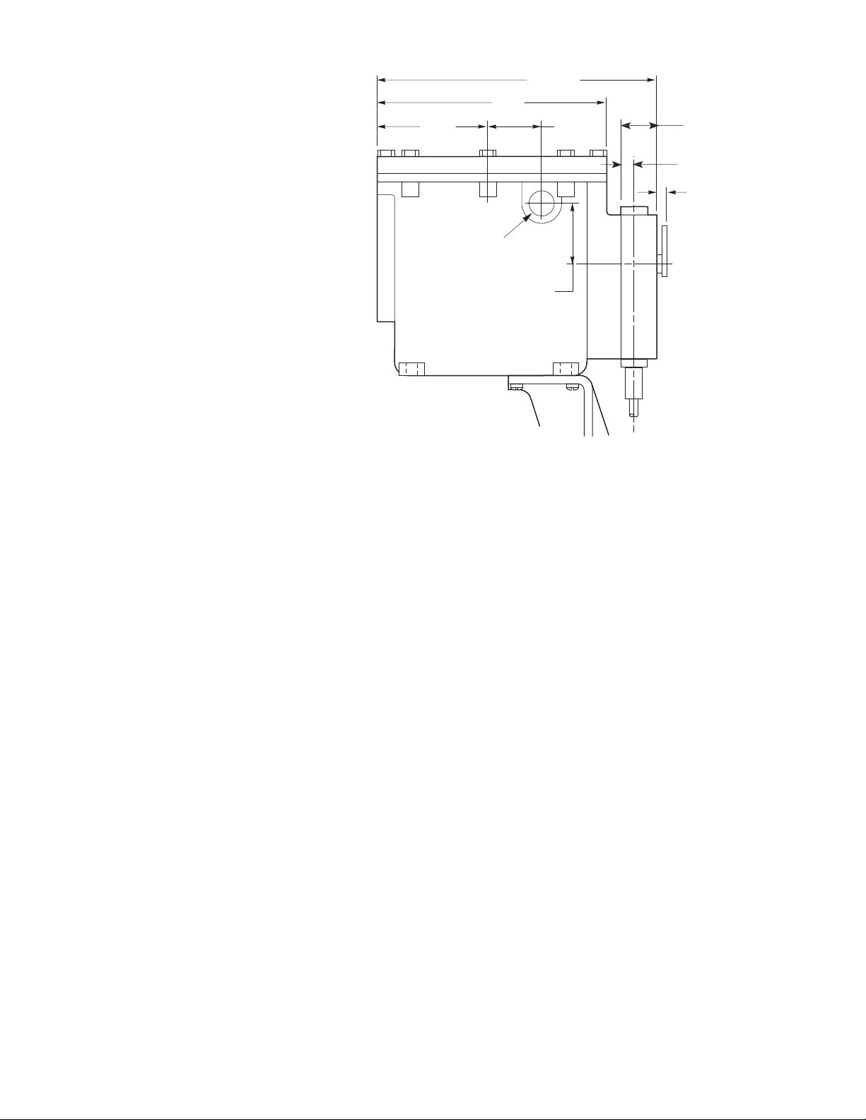
4-1/2
(114)
2-15/16
(51)
2-1/8
(54)
3/4 (19) Pipe Tap
On Each Side
9
(229)
10-13/16
(275)
1/8
(3)
1-1/4 (32)
5/8 (16)
Dimensions shown
are in inches (mm).
Figure-10 Hazardous Location Actuator Side Dimensions.
F-08366-15 © Copyright 2012 Schneider Electric All Rights Reserved. 11

© Copyright 2012, Schneider Electric
All brand names, trademarks and registered
trademarks are the property of their respective
owners. Information contained within this
document is subject to change without notice.
F-08366-15
 Loading...