


 Loading...
[Stand (option)] |
[Wall-mounting] |
The unit in this picture is UB-5315 series. (Stand kit is optional.)
Electronic Board
Operating Instructions
Model No. UB-5315
UB-5815
English . . . . . . . . . . . . . . . . . .1–36 Français . . . . . . . . . . . . . . . .37–72 Deutsch . . . . . . . . . . . . . . .73–108 Español . . . . . . . . . . . . . .109–144 Italiano . . . . . . . . . . . . . . .145–180 Nederlands . . . . . . . . . . .181–216 Svenska . . . . . . . . . . . . . .217–252
. . . . . . . . . . . . . . . .253–288 Русский . . . . . . . . . . . . . .289–324
Español Deutsch Français English
Svenska Nederlands Italiano
•To assemble this unit, please refer to the Installation Manual.
•Before operating this unit, please read these instructions completely and keep them carefully for future reference.
•Because of the nature of the print film, all the printed text will remain on the film.
Русский

Thank you for purchasing the Panasonic Electronic Board.
For optimum performance and safety, please read these instructions carefully.
Record these items for future reference
Model number: _________________________ |
Date of purchase: ________________________ |
Serial number: _________________________ |
Dealer’s name: __________________________ |
Dealer’s address: |
Tel: |
Accessories
|
Q’ty |
|
Q’ty |
• Thermal transfer film . . . . |
. . . . . . . . . . 1 |
• Power cord . . . . . . . . . |
. . . . . . . . . . 1 |
• Markers (red, black, and blue) |
. . . . . . 1 each |
• A4 (Letter*) size copy paper |
. . . . . . . . . 20 |
• Operating Instructions . . . |
. . . . . . . . . . 1 |
• Software CD-ROM . . . . . |
. . . . . . . . . . 1 |
• Installation Manual . . . . . |
. . . . . . . . . . 1 |
• Software License Agreement |
. . . . . . . . . . 1 |
• Eraser . . . . . . . . . . . . |
. . . . . . . . . . 1 |
|
|
*Letter size is for U.S.A. and Canada models.
*The stand is optional. By way of example, this manual describes an Electronic Board which is used with the stand.
*USB cable is not included.
•Microsoft, Windows and Windows NT are either registered trademarks or trademarks of Microsoft Corporation in the United States and/or other countries.
Windows® is Microsoft® Windows® operating system.
Screen shots reprinted with permission from Microsoft Corporation.
•IBM is a registered trademark of International Business Machines Corporation.
•Pentium is a registered trademark of Intel Corporation in the U.S. and other countries.
•Adobe and Acrobat are registered trademarks of Adobe Systems Incorporated.
•All trademarks referred to in this manual are property of their respective companies.
The information given in this Operating Instructions is subject to change without notice.
Warning about saving data
When the system storage device or any of its optional storage device is adversely effected by operational errors, static electricity, electrical noise, vibration, dust or when the power has been cut off due to malfunction, repair or inadvertently, the memory contents may be lost or changed. Before operating the system, make a point of reading the precautionary notes in the Operating Instructions and the help information, and observe them during operation.
Please observe carefully the following precaution:
• Make absolutely sure that all important data is saved by back-up or the original is saved.
The manufacturer hereby declares that it cannot be held accountable for any loss or change in any data stored on floppy disks, hard disks, optical disks, or other memory devices.
2

|
Table of Contents |
|
|
|
Page |
|
For Your Safety . . . . . . . . . . . . . . . . . . . . . . . . . . . . . . . . . . . . . . |
. . 4 |
Before |
Precautions . . . . . . . . . . . . . . . . . . . . . . . . . . . . . . . . . . . . . . . . . . |
. 5 |
You Start |
• CD-ROM . . . . . . . . . . . . . . . . . . . . . . . . . . . . . . . . . . . . . . . . . . . . . . . . . . . . . |
. 6 |
Part Names and Functions . . . . . . . . . . . . . . . . . . . . . . . . . . . . . . . 8
• Control panel . . . . . . . . . . . . . . . . . . . . . . . . . . . . . . . . . . . . . . . . . . . . . . . . . . . 9
Installing the Thermal Transfer Film . . . . . . . . . . . . . . . . . . . . . . 10
Loading Copy Paper . . . . . . . . . . . . . . . . . . . . . . . . . . . . . . . . . . . 12
Making Copies . . . . . . . . . . . . . . . . . . . . . . . . . . . . . . . . . . . . . . . . 14
• Copy types and procedures . . . . . . . . . . . . . . . . . . . . . . . . . . . . . . . . . . . . . . 15
|
Replacing the Thermal Transfer Film . . . . . . . . . . . . . . . . . . . . . |
16 |
|
Paper Jams . . . . . . . . . . . . . . . . . . . . . . . . . . . . . . . . . . . . . . . . . . |
17 |
Using |
|
|
|
Screen Height Adjustment . . . . . . . . . . . . . . . . . . . . . . . . . . . . . . |
20 |
|
Computer Interfacing . . . . . . . . . . . . . . . . . . . . . . . . . . . . . . . . . . |
22 |
|
• System requirements . . . . . . . . . . . . . . . . . . . . . . . . . . . . . . . . . . . . . . . . . . . |
22 |
|
• Contents of CD-ROM . . . . . . . . . . . . . . . . . . . . . . . . . . . . . . . . . . . . . . . . . . . |
22 |
|
• Connecting the unit to a computer . . . . . . . . . . . . . . . . . . . . . . . . . . . . . . . . . |
22 |
|
• Installing the driver and software . . . . . . . . . . . . . . . . . . . . . . . . . . . . . . . . . . |
23 |
|
• Removing the driver and software . . . . . . . . . . . . . . . . . . . . . . . . . . . . . . . . . |
29 |
|
• Scanning . . . . . . . . . . . . . . . . . . . . . . . . . . . . . . . . . . . . . . . . . . . . . . . . . . . . . |
29 |
|
• Panaboard Operation Panel . . . . . . . . . . . . . . . . . . . . . . . . . . . . . . . . . . . . . . |
30 |
|
• Printing . . . . . . . . . . . . . . . . . . . . . . . . . . . . . . . . . . . . . . . . . . . . . . . . . . . . . . |
31 |
|
Daily Care and Maintenance . . . . . . . . . . . . . . . . . . . . . . . . . . . . . |
32 |
|
• Cleaning the screen and the unit . . . . . . . . . . . . . . . . . . . . . . . . . . . . . . . . . . |
32 |
|
• Caring for the eraser . . . . . . . . . . . . . . . . . . . . . . . . . . . . . . . . . . . . . . . . . . . . |
32 |
|
• Cleaning the printer head, platen roller and pick-up roller . . . . . . . . . . . . . . . |
32 |
Help |
|
|
|
Troubleshooting . . . . . . . . . . . . . . . . . . . . . . . . . . . . . . . . . . . . . . |
34 |
|
• Meanings of error codes . . . . . . . . . . . . . . . . . . . . . . . . . . . . . . . . . . . . . . . . . |
35 |
Specifications . . . . . . . . . . . . . . . . . . . . . . . . . . . . . . . . . . . . . . . . 36
• Option and Separately available . . . . . . . . . . . . . . . . . . . . . . . . . . . . . . . . . . . 36
English
3
For Your Safety
English
CAUTION:
TO PREVENT RISK OF ELECTRIC SHOCK HAZARD, DO NOT REMOVE THE COVER OF THIS PRODUCT, REFER SERVICING TO QUALIFIED SERVICE PERSONNEL.
WARNING:
TO PREVENT FIRE OR SHOCK HAZARD, DO NOT EXPOSE THIS PRODUCT TO RAIN OR ANY TYPE OF MOISTURE.
THE SOCKET-OUTLET MUST BE NEAR THIS EQUIPMENT AND MUST BE EASILY ACCESSIBLE.
The product should be used only with the power cord that is supplied by the manufacturer.
•(220–240 V equipment)
A certified power supply cord has to be used with this equipment. The relevant national installation and/or equipment regulations shall be considered. A certified power supply cord is not lighter than ordinary polyvinyl chloride flexible cord according to IEC 60227 (designation H05VV-F 3G 1.0 mm2).
CLASS 1 LED PRODUCT
4
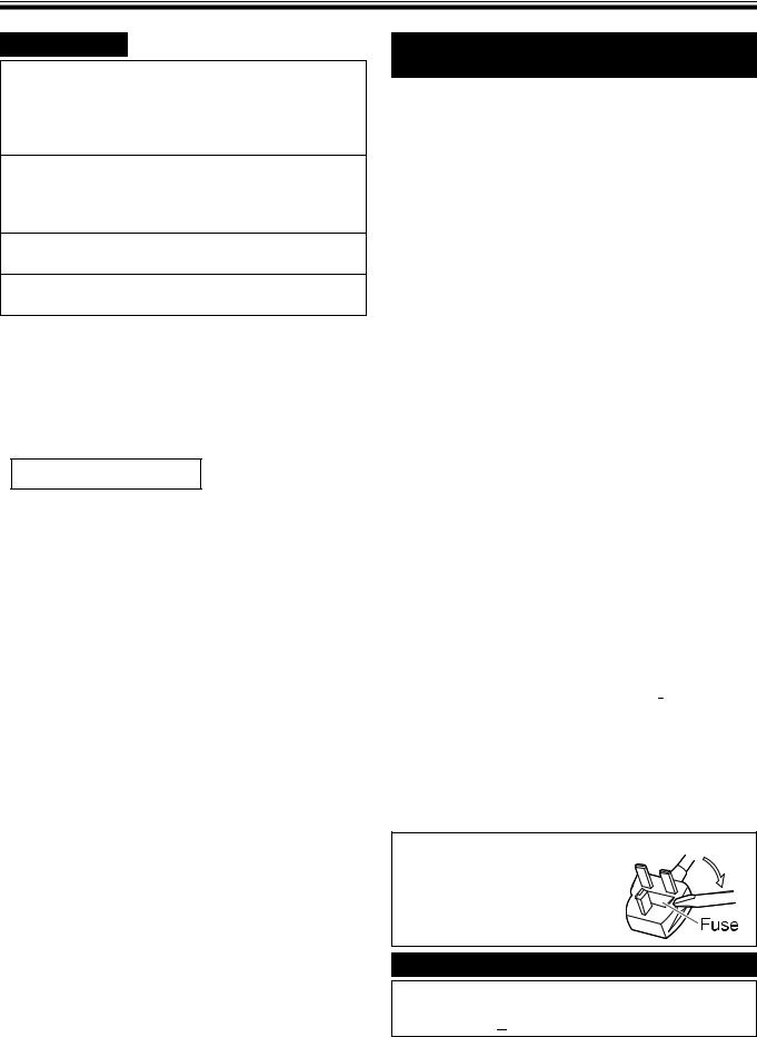
For users in
the United Kingdom only
Safety Information
This appliance is supplied with a moulded three pin mains plug for your safety and convenience.
A 5 amp. fuse is fitted in this plug. Should the fuse need to be replaced please ensure that the replacement fuse has a rating of 5 amps. and that it is approved by ASTA or BSI to BS1362. Check for the ASTA mark  or the BSI mark
  on the body of the fuse. If the plug contains a removable fuse cover you must ensure that it is refitted when the fuse is replaced. If you lose the fuse cover the plug must not be used until a replacement cover is obtained. A replacement fuse cover can be purchased from your local Panasonic Dealer.
If the fitted moulded plug is unsuitable for the socket outlet in your home then the fuse should be removed and the plug cut off and disposed of safely.
There is a danger of severe electrical shock if the cut off plug is inserted into any 13 amp. socket.
If a new plug is to be fitted please observe the wiring code as shown below. If in any doubt please consult a qualified electrician.
WARNING: This appliance must be earthed. IMPORTANT: The wires in this mains lead are coloured in accordance with the following code.
Green-and-Yellow: Earth
Blue: Neutral Brown: Live
As the colours of the wire in the mains lead of this appliance may not correspond with the coloured markings identifying the terminals in your plug, proceed as follows.
The wire which is coloured Green-and-Yellow must be connected to the terminal in the plug which is marked with the letter E or by the Earth symbol  or coloured Green or Green-and-Yellow.
The wire which is coloured Blue must be connected to the terminal in the plug which is marked with the letter N or coloured Black.
The wire which is coloured Brown must be connected to the terminal in the plug which is marked with the letter L or coloured Red.
How to replace the fuse:
Open the fuse compartment with a screwdriver and replace the fuse.
Für Benutzer in der BRD
Hinweis:
Der arbeitsplatzbezogene Geräuschemissionswert dieses Gerätes beträgt  70 dB(A) nach DIN 45635 Teil 19.
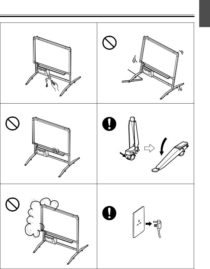
Precautions
Never remove the cover, take apart or modify the |
Do not position the electronic board in a location where |
||
product. This will void the warranty. |
it is unstable. |
||
|
|
|
|
|
|
|
|
Do not put drinks, other liquids or heavy items on the |
After installing or moving the electronic board, lock the |
tray or screen. |
casters and set the fall-prevention extension legs. |
|
Push to lock |
|
Locking the casters |
|
(Push this side) |
Do not use the electronic board in an excessively |
If the electronic board is not going to be used for an |
humid or dusty location. |
extended period of time (e.g., during extended |
|
holidays), turn off the power and remove the plug from |
|
the wall outlet. |
English
5

Precautions
Do not lean against the screen or on the cover (lower), The screen height must be adjusted by two people. even if the electronic board is mounted on the wall.
Confirm both sides of the screen are hung in the same |
Make sure to tighten the height adjustment handles |
||
height slots. |
after adjusting the screen height. |
|
|
Slot 3 |
|
Tighten |
|
|
the height |
||
|
|
||
Slot 3 |
Tighten |
adjustment |
|
handles |
|||
Slot 2 |
the height |
||
|
|||
|
adjustment |
|
|
Slot 2 |
handles |
|
|
Slot 1 |
|
|
|
 Slot 1
■CD-ROM
To prevent the CD-ROMs from accidental damages:
Do not touch or write on the surface |
Do not leave the disc out of the |
Do not leave the disc in direct |
of the disc. |
protective case. |
sunlight or near heat sources. |
|
|
|
|
|
|
Do not place heavy objects on the |
To clean the disc, hold the disc by |
|
|||
disc case or drop the case. |
its edges and wipe it from the |
|
|||
|
|
center to the edges with a dry, soft |
|
||
|
|
|
|||
|
|
cloth. |
|
||
|
|
|
|
|
|
6
Precautions
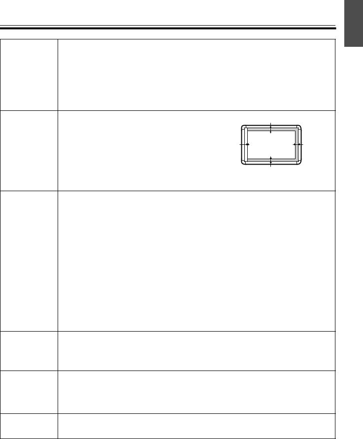
Installation • Do not install the unit where it may be exposed to direct sunlight, near heating equipment, or near air-conditioning vents as this may cause stretching and/or discoloration of the screen.
•Do not install the unit in strong sunlight or strong lighting. Proper copying may become impossible.
•Do not install the unit in locations where the temperature may change suddenly as this may disable the unit’s ability to make copies.
Screen Film |
• Make thick and dark lines inside the copying |
|
25 mm |
|
|
area. Note that any writing inside the shaded |
|
|
|
|
|
|
|
|
|
area (on right) cannot be copied. |
|
|
|
|
• Do not allow writing to remain on the screen for |
0 mm |
Copying area |
12.5 mm |
|
an extended period of time as it will become |
|
|
|
|
harder to erase. |
|
|
|
25mm
•Do not touch the screen, write with markers, or
erase while the screen is moving as this may result in damage to the unit.
Markers, |
• Use only the included or designated markers, erasers and thermal transfer film. |
Erasers and |
(See page 36.) |
Thermal |
Use of accessories other than those included or designated (such as oil-based |
Transfer Film |
markers) may damage the screen or result in hard-to-erase markings. |
•Do not store the thermal transfer film in a location subject to extreme changes in temperature (such as near air conditioning or heating equipment) as this may cause condensation on the thermal transfer film and result in poor print quality and/or paper jams.
•The length of one roll of designated thermal transfer film (Replacement film: UG6001) is approximately 50 meters. One roll of thermal transfer film can make approximately 150 sheets of copies.
Note that the total number of copies may differ depending on the operating conditions. Also note that the length of the thermal transfer film supplied with the unit is shorter than the replacement film roll and is only approximately 10 meters.
•Store markers horizontally as vertical storage may stop the ink from coming out.
Power Cord • When moving the unit, disconnect the power cord from the electrical power socket and from the printer’s power connector and coil it for transportation as stepping on the power cord or having it catch on something during movement may result in damage to the cord.
Replacing |
• Dispose of the used thermal transfer film in a trash receptacle for burnable trash. |
|
the Thermal |
• A negative of the copied image will remain on the thermal transfer film. (To protect |
|
Transfer Film |
||
the security of your information, we recommend cutting up the used thermal transfer |
||
|
||
|
film with scissors or shredder before disposing of it.) |
USB Cable • Use a shielded USB cable that is certified as logo by USB-IF.
• If you connect the electronic board to a USB hub, it is not guaranteed to work.
English
7
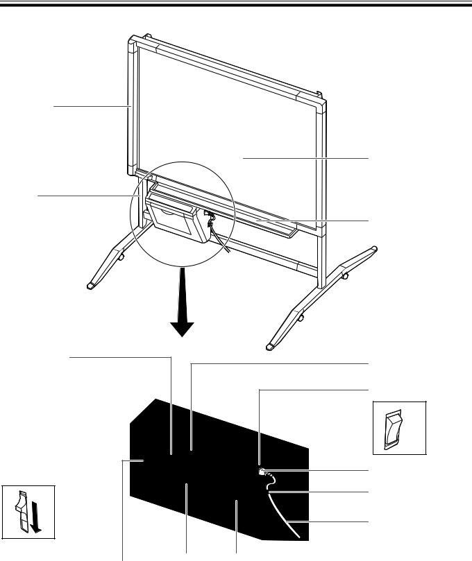
Part Names and Functions
Scanner
Stand
The stand is optional.
Output Port
This port holds up to 10 sheets of output paper.
Printer Open Lever 
Push down this lever to open the printer door.
USB Connector |
|
Paper Cover |
Printer Door |
|
|||
(See page 22.) |
|
Open this cover to |
Open this door to load a |
|
|
load copy paper. |
thermal transfer film or to |
|
|
|
remove jammed paper. |
|
|
|
(See pages 10, 17.) |
Screen Film
Tray
Control Panel
(See page 9 for details.)
Power Switch
ON
OFF
AC Inlet
Cord Holder
Power Cord
8
Part Names and Functions
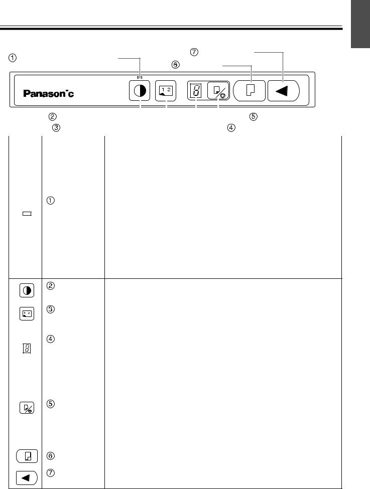
■Control panel
Contrast/Remaining Film |
Advance Key |
|
Copy Key |
||
Indicator |
|
|
|
|
|
|
|
|
|
|
|
|
|
|
|
|
|
Multi-Copy/Stop Key |
|
|
|
|
|
|
|
|
|
|
|
|
|
|
|
|
|
|
|
|
|
|
|
|
|
|
|
|
|
|
|
|
|
|
|
|
|
|
|
|
|
|
|
|
|
|
|
|
|
|
|
|
|
|
|
|
|
|
|
|
|
|
|
|
|
|
|
|
|
|
|
|
|
Contrast Key |
|
|
|
|
|
|
|
|
|
|
|
|
|
|||
|
|
|
|
|
|
|
|
|
|
|
|
|
|
||||
|
2-Screen Copy Key |
|
|
|
|
|
|
|
|
Multi-Copy/Error Indicator |
|||||||
|
|
|
|
|
|
|
|
|
|||||||||
|
|
|
|
|
|
|
|
|
|
|
|
|
|
|
|
|
|
Panel |
Name |
|
|
|
|
|
Description |
||||||||||
|
|
|
|
|
|
|
|
|
|
|
|
|
|
|
|
|
|
|
|
|
This lamp indicator notifies the user when the time to replace the |
||||||||||||||
|
|
|
thermal transfer film is approaching (estimated) and of the |
||||||||||||||
|
|
|
printing contrast used during copying. |
||||||||||||||
|
|
|
Indicator off: |
Normal printing contrast |
|||||||||||||
|
Contrast/ |
Indicator on: |
Darker than normal printing contrast |
||||||||||||||
|
Indicator flashing*: Almost time to replace the thermal transfer |
||||||||||||||||
|
Remaining |
|
|
|
|
film |
|||||||||||
|
Film |
|
|
|
|
(Note that only about 15 more sheets may be |
|||||||||||
|
Indicator |
|
|
|
|
copied when this indicator starts flashing.) |
|||||||||||
|
|
|
|
|
|
|
Replacement film (UG-6001) is separately available |
||||||||||
|
|
|
|
|
|
|
from the dealer where you purchased your unit. |
||||||||||
*The flashing indicator will go out after the power is turned off and the printer has been opened and closed. (When copying is performed, this indicator will begin flashing again.)
|
|
|
Contrast |
Each time this key is pressed, the unit will alternate between |
|
|
|
Key |
normal and dark contrast modes (Normal/Dark). |
|
|
|
|
|
|
|
|
2-Screen |
This key causes the front and back of the screen to be copied on |
|
|
|||
|
|
|
Copy Key |
a single sheet of paper. |
|
|
|||
|
|
|
|
|
|
|
|
Multi-Copy/ |
This indicator displays the number of copies to be made. The |
|
|
|
display changes each time the Multi-Copy/Stop Key is pressed. |
|
|
|
|
Error |
Example: 1 → 2 → ··· → 9 → 1 → ··· |
|
|
|
Indicator |
When an error occurred, a flashing symbol will appear in this display to |
|
|
|
|
indicate the error status. (See page 35.) |
|
|
|
|
|
|
|
|
|
When making multiple copies, press this key until the desired |
|
|
|
|
number of copies is displayed on the Multi-Copy/Error Indicator. |
|
|
|
Multi-Copy/ |
This key can also be pressed while multiple copies are being |
|
|
|
made to stop the copying process. The display indication |
|
|
|
|||
|
|
|
Stop Key |
changes while multiple copies are being made as shown below. |
|
|
|
|
After reaching 0, the display will reset to 1. |
|
|
|
|
Example: 5 → 4 → 3 → 2 → 1 → 0 → 1 |
|
|
|
|
(countdown display during copying) |
|
|
|
|
|
|
|
|
Copy Key |
This key causes the screen to be copied. |
|
|
|
||
|
|
|
|
|
|
|
|
Advance |
This key advances the screen from right to left. |
|
|
|
Key |
|
|
|
|
|
English
9
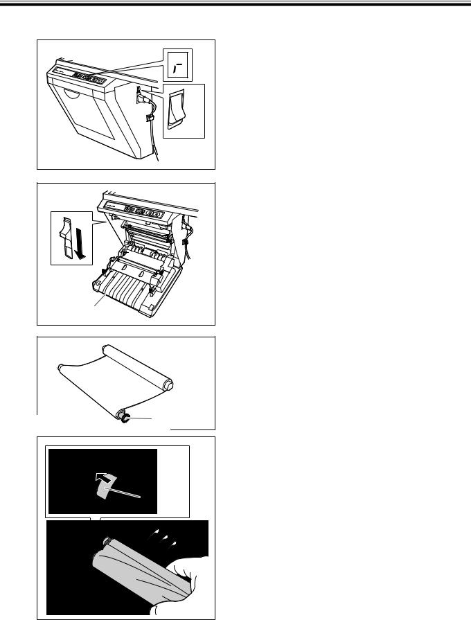
Installing the Thermal Transfer Film
Install the thermal transfer film in the printer.
1 |
ON |
OFF |
2 |
Printer door
Set the power switch to on ( I ).
•“  ” will flash on the Multi-Copy/Error Indicator when the thermal transfer film has run out.
Push down the printer open lever and open the printer door.
3 |
Blue gear |
Blue shaft |
Install the thermal transfer film.
1)Set the thermal transfer film, with the blue gear in front, on the right.
2)Insert the blue shaft into the front left hole.
10
|
Installing the Thermal Transfer Film |
|
|
3) Place the blue gear on the front right groove. |
|
|
Blue gear |
|
|
4) Place the white shaft on both sides of the back |
|
|
grooves. |
|
4 |
White shaft |
|
Tighten the film, then close the printer door. |
||
|
||
|
1) Rotate the blue gear in the direction of the arrow |
|
|
to take up the slack on the film. |
|
|
• If a slack remains, perform step 3-2) through 4-1) again. |
|
|
Blue gear |
2)Securely close the printer door by using both hands until a click is heard.
|
• “ ” flashing on the Multi-Copy/Error Indicator will go |
Latches |
out. |
|
Notes
•If “  ” is still flashing after closing the printer door, make sure that the thermal transfer film has been installed properly and tightened.
•The printer door should be closed to make copies properly. Confirm both latches are locked.
English
11
Loading...