


Model No.
TY-WK42PV2W
Plasma display wall hanging bracket (Vertical mounting type)
Fitting Instructions
Before commencing work, carefully read these Instructions and the Manual for the wide plasma display to ensure that fitting is performed correctly. (Please save these instructions. You may need them when maintaining or moving the bracket.)
Wandhalterung zum Anbringen des Plasmadisplays (Typ für vertikale Anbringung)
Anleitung zur Anbringung
Vor der Ausführung lesen Sie bitte diese Anleitung und die Bedienungsanleitung für das Plasmadisplay sorgfältig durch, damit die Anbringung richtig ausgeführt wird. (Bitte bewahren Sie diese Anleitung auf. Sie kann bei der Wartung oder der erneuten Anbringung der Halterung benötigt werden.)
Muurbevestigingssteun voor plasmascherm (voor verticale montage)
Montage-instructies
Lees deze installatiehandleiding en de bedieningshandleiding voor het breedbeeld-plasmascherm zorgvuldig door voordat u begint, zodat de montagewerkzaamheden op de juiste wijze worden uitgevoerd. (Bewaar deze handleiding. U hebt de handleiding weer nodig wanneer u de bevestigingssteun verwijdert of verplaatst.)
Staffa per montaggio alla parete dello schermo al plasma (tipo per montaggio verticale)
Istruzioni per il montaggio
Prima di iniziare il montaggio leggere attentamente queste istruzioni ed il manuale dello schermo al plasma allargato per poter procedere al montaggio in modo corretto. (Conservare poi queste istruzioni che si renderanno necessarie per la manutenzione e l’eventuale spostamento della staffa.)
Applique de fixation au mur (type pour montage vertical)
Instructions de montage
Avant de commencer le travail, lisez attentivement ces instructions ainsi que le mode d'emploi de l'écran large à plasma de manière à réaliser un montage convenable. (Conservez soigneusement les présentes instructions. Vous pouvez en avoir besoin pour effectuer un entretien ou si vous désirez déplacer l'applique.)
Soporte para colgar la pantalla de plasma en una pared (Tipo de montaje vertical)
Instrucciones de instalación
Antes de empezar el trabajo, lea atentamente estas instrucciones y el manual de la pantalla panorámica de plasma para asegurar una instalación correcta. (Guarde estas instrucciones. Podrá necesitarlas cuando haga trabajos de mantenimiento o mueva el soporte.)
Väggupphängningshållare för plasmaskärm (vertikal monteringstyp)
Monteringsanvisningar
Innan arbetet påbörjas ska du noga läsa dessa anvisningar och bruksanvisningen som medföljer plasmaskärmen för att försäkra att arbetet utförs på rätt sätt. (Bevara dessa anvisningar. Du kan behöva anlita dem på nytt för underhåll eller flyttning av hållaren.)
Vægophæng til plasmaskærm (Type til lodret montering)
Opsætningsinstruktioner
Før arbejdet påbegyndes, skal De omhyggeligt læse disse instruktioner og betjeningsvejledningen til widescreen-plasmaskærmen for at sikre at opsætningsarbejdet udføres korrekt.
(Gen disse instruktioner. De kan få brug for dem ved vedligeholdelse, eller hvis ophænget skal flyttes.)
English
Italiano Nederlands Deutsch
Français
Español
Svenska
Dansk
TQZH485

Safety precautions [Always follow these precautions]
English
WARNING
Fitting work and connection equipment expansion should never be done by any other than a qualified installation specialist.
• Incorrect fitting may cause equipment to fall, resulting in injury.
Include a safety factor when considering the strength of the proposed fitting location.
• If strength is not sufficient the equipment may fall, resulting in injury.
When expanding connection equipment, be sure to prevent lock release.
• This may cause injury.
Do not fit at a location that cannot bear the load.
• If the fitting location lacks sufficient strength the equipment may fall.
CAUTION
Do not fit at any locations subject to humidity, dust, smoke, steam or heat.
• This may have an adverse effect on the plasma TV and cause fire or electric shock.
The work of fitting or removing the plasma TV must be performed by at least two people.
• The plasma TV may fall and cause injury.
Do not fit facing upwards, sideways or upside down.
• This may cause heat to build up inside the plasma TV unit, resulting in a fire.
Provide spacing around the plasma TV of at least 100 mm (3 15/16 inches ) to the top and right side, at least 300 mm (11 13/16 inches ) to the left side, at least 60 mm (2 23/64 inches ) to the bottom and at least 42 mm (1 21/32 inches ) to the rear.
•The plasma TV unit has air blow holes on the top, and air suction holes on the bottom and rear.
Covering these may result in a fire.
Requests regarding handling
1)Exercise care when selecting the location for the TV because it may discolor or deform due to light or heat if it is placed where it is exposed to direct sunlight, or near a heater.
2)Upkeep
Wipe with a dry cloth. If the unit is extremely soiled, first wipe off soiling with a neutral detergent diluted in water, and then wipe with a dry cloth. Do not use cleaners such as benzene, thinner or furniture wax because they may cause paint peeling. (If using a chemical wiping cloth, follow any precautions included.)
3)Do not affix adhesive tape or stickers to the product. Either may stain the wall hanging bracket or surface of the wiring cover for close-to-the-wall installation.
2

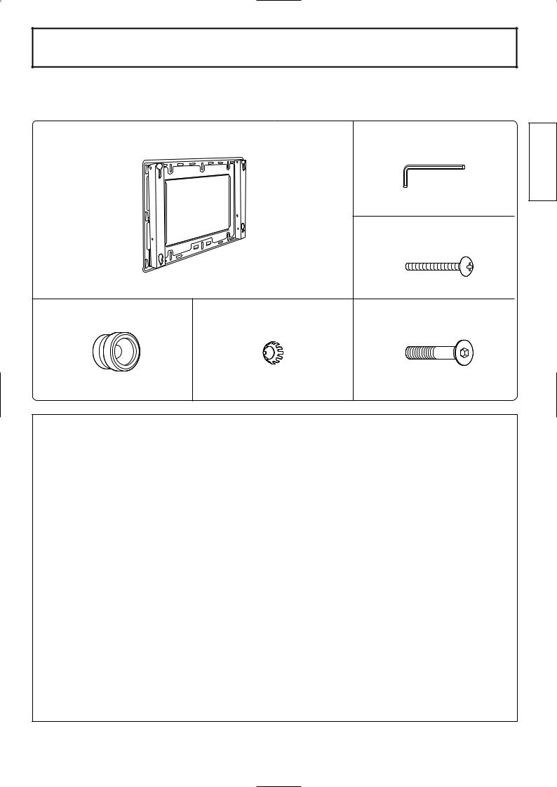
Components
TY-WK42PV2W Wall hanging bracket (Vertical mounting type)
Wall hanging bracket . . . x1 |
|
Allen wrench (included tool) |
|
|
. . . x1 |
|
|
Unit fastening screws (M5-35) |
|
|
. . . x2 |
Insulation spacers . . . x4 |
Dished toothed washers . . . x4 |
Allen head countersunk screws |
|
|
(M8-55) . . . x4 |
English
Precautions for wall hanging bracket fitting
♦The wall hanging bracket is for use in attaching a plasma TV unit to a vertical wall for viewing. Do not fit to any surface other than a vertical wall.
♦The equipment has a lock mechanism on the left side, so provide at least 300 mm (11 13/16 inches ) of space from the wall surface.
♦To ensure correct plasma TV performance and prevent trouble, do not fit at any of the following locations.
•Near sprinklers or fire/smoke detectors
•Where there is a risk of exposure to vibration or impact
•Near high-voltage wires or dynamic power supplies
•Locations exposed to air blown from heating equipment
♦Fit using techniques suited to the structure and materials of the fitting location.
♦Use commercially available M6 screws suited to the wall surface material (wood, steel frame, concrete etc.) for fitting the bracket to the wall.
♦Fit so there is no contact between the attachment screws or power cord and any metal inside the wall.
♦For the TV power supply plug, use a power supply outlet that can be reached easily.
♦Ensure good air flow so that the equipment ambient temperature does not exceed 40°C. Failure to do this may cause heat to build up inside the plasma TV, resulting in malfunction.
3

English
Fitting procedure ( TYWK42PV2W )
1. Confirm the strength of the proposed fitting location
The weight of the wall hanging bracket is approximately 6 kg (13 Ib.). The plasma TV unit attached to the wall hanging bracket weighs approximately 29.5 (65 Ib.) to 35 kg (77 Ib.).
Check the wall strength at the 6 attachment locations by referring to the dimension drawing of the wall hanging bracket (given below), and provide adequate reinforcement if strength is not sufficient.
A |
|
775(30 33/64) |
|
735(28 15/16) |
|
660(25 63/64) |
|
Display outer profile |
|
12 19/32) |
B |
320( |
|
11.0(7/16) |
|
Unit: mm (inches)
Dimensions of clearance required around wall hanging bracket
A |
B |
C |
For 37-inch 1070 (42 1/ 8) 596 (23 15/32) 120 ( 4 47/64)
For 42-inch 1170 (46 1/16) 656 (25 53/64) 150 ( 5 29/32)
bracket unit |
Wall attachment holes |
|
(at 6 points) |
spacing for the plasma TV of at least 100 mm (11 13/16 inches ) to the top and right side, at
mm(3 15/16 inches ) to the left side, at least 60 mm (2 23/64 inches ) to the bottom and at mm (1 21/32 inches ) to the rear.
Notes
22 holes in the wall hanging bracket. If the wall material is wood, and adequate attachment cannot be ensured by fastening at the 6 points at right, use as many spare holes as necessary. exercise care because some wall materials may crack if screws are located too close together. dimensions are important. Do not fit at any location where these dimensions cannot be
2 |
hanging bracket to wall |
the arrow marks on the wall hanging bracket point upward.
consists of a material such as concrete and bolts or nuts must be embedded beforehand,
the hole positions by aligning using the actual wall hanging bracket, or calculate hole positions the dimension drawing, and then embed "M6" bolts or nuts.
bolts, locate so that the bolts protrude from the wall
(25/64 inches) to 15 mm(19/32 inches).
the screw at the top center hole first.
a level, correct any bracket inclination, and then fasten screws 5 locations.
Note
•Use commercially available M6 screws suited to the wall surface material (wood, steel frame, concrete etc.) for fitting the bracket to the wall.
4

3. Prepare the plasma TV
Fit the insulation spacers to the plasma TV.
Place the plasma TV unit face down on a blanket or other soft cloth that is clean and free of debris, and follow the procedure below.
Flathead screwdriver
Caps
 Allen wrench
4. Fit and fasten the plasma TV unit to the wall hanging bracket 

Fitting procedure
(1)Locate the insulation spacers on the top of the plasma TV unit into the notch on the top of the wall hanging bracket, and slide down.
(2)Lift the plasma TV unit a little, insert the bottom insulation spacers into the holes on the bottom of the wall hanging bracket, and slide the unit down.
(3)Attach securely using the included unit fastening screws (1 each for left and right).
Note
(1) Wall 
hanging

 Wall
Wall
(3)
Lower hole
Insulation spacer
(2)
the unit fastening screws to ensure that the plasma TV unit accidentally dislodged from the wall hanging bracket.
5. Fasten wall hanging bracket
procedure
(1)After wiring, remove the red screw for open/close fastening (on the left side), lift the TV unit towards yourself once, and then slowly lower it. The lock will release.
(2)Securely tighten the red screws for open/close fastening (1 each on the left and right)  on the sides of the wall hanging bracket.
Note
the red screws for open/close fastening to ensure that TV unit cannot be accidentally dislodged.
Wall handing |
|
bracket |
|
Fitting hole for red screw |
Wall |
for open / close fastening |
|
 Red screw for open / close fastening
6. Removal of plasma TV unit
Removal procedure
(1)Remove the screws for unit fastening (1 each on the left and right) that are fitted to the wall hanging bracket sides.
(2)While lifting the bottom of the plasma TV unit, pull it towards yourself.
(3)When the lower insulation spacers are freed, keep lifting upward.
Wall |
|
(3) |
|
hanging |
|
|
|
bracket |
Wall |
Wall |
|
(1) |
|||
|
|
||
Screw for |
|
|
|
plasma TV |
|
||
unit |
|
(2) |
|
fastening |
|
||
|
|
||
|
|
Insulation spacer |
|
English
5
Warranty
English
Panasonic Consumer Electronics Company |
Panasonic Sales Company, Division of |
||
Division of Matsushita Electric Corporation |
Matsushita Electric of Puerto Rico, Inc. |
||
of America |
AVE. 65 de Infanteria, Km 9.5 |
||
One Panasonic Way |
San Gabriel Industrial Park |
||
Secaucaus, NJ |
Carolina, Puerto Rico 00985 |
||
07094 |
|
|
|
|
|
|
|
|
|
|
|
|
|
|
|
|
|
|
|
RACKS AND STANDS
Panasonic Consumer Electronics Company or Panasonic Sales Company (collectively referred to as “the warrantor” ), will replace parts in case of defects in materials or workmanship, free of change, in the USA or Puerto Rico, for ten (10) days from the date of the original purchase.
In-warranty parts in the USA |
can be obtained during the warranty period be contacting: |
|
Panasonic Services Company (PASC) |
|
20421 84th Avenue South |
|
Kent, Washington 98032 |
|
Tel.:1-800-833-9626 |
|
Fax.:1-800-237-9080 |
(6 am to 5 pm Monday-Friday; 6 am to 10:30 am Saturday; PST)
Service in Puerto Rico can be obtained during the warranty period by calling the telephone number listed above.
This warranty is extended only to the original purchaser. A purchase receipt or other proof of the original purchase is required for replacement parts under the warranty.
This warranty only covers failures due to materials and workmanship and does not cover normal wear. The warranty does not cover damages which occurred in shipment or failures which result from accidents, misuse, abuse, neglect, mishandling, misapplication, faulty installation, set-up adjustments, improper maintenance, alteration, line power surge, lightning damage, modification,or commercial use, such as hotel, office, restaurant, or other business or rental use of the product, or damage that is attributable to acts of God.
LIMITS AND EXCLUSIONS
There are no express warranties except as listed above.
PANASONIC SHALL NOT BE LIABLE FOR INCIDENTAL OR CONSEQUENTIAL DAMAGE RESULTING FROM THE USE OF THIS PRODUCT, OR ARISING OUT OF ANY BREACH OF THIS WARRANTY. ALL EXPRESS AND IMPLIED WARRANTIES. INCLUDING THE WARRANTIES OF MERCHANTABILITY, ARE LIMITED TO THE APPLICABLE WARRANTY PERIOD SET FORTH ABOVE.
Some states do not allow the exclusion or limitation of incidental or consequential damages, or limitations on how long an implied warranty lasts, so the above exclusions or limitations may not apply to you.
This warranty gives you specific legal rights and you may also have other rights which vary from state to state. If a problem with this product develops during or after the warranty period, you may contact your dealer or call the number listed above.
If the problem is not handled to your satisfaction, then write to the Customer Satisfaction Center at the Panasonic Consumer Electronics Company address indicated above.
6

English
7
Deutsch
Sicherheitsmaßnahmen
[ Folgen Sie immer diesen Vorsichtsmaßnahmen. ]
Warnung
Das Anbringen und die Verbindung der Geräte sollte immer von einer für die Installation qualifizierten Person ausgeführt werden.
•Falsches Zubehör kann zum Herunterfallen des Gerätes und zur Verletzung von Personen führen.
Aus Sicherheitsgründen sollte die Festigkeit des vorgesehenen Anbringungsortes immer sichergestellt werden.
•Wenn keine ausreichende Festigkeit gegeben ist, kann dies zum Herunterfallen des Gerätes und zu Verletzungen von Personen führen.
Beim Anschluß anderer Geräte ist sicherzustellen, dass ein Ausrasten verhindert wird.
• Dies kann zu Verletzungen führen.
Nicht an einem Ort anbringen, der das Gewicht des Gerätes nicht tragen kann.
•Wenn der Anbringungsort keine ausreichende Festigkeit aufweist, kann das Gerät herunterfallen.
Vorsicht
Nicht an einem Ort anbringen, an dem Feuchtigkeit, Staub, Rauch, Dampf oder übermäßige Wärme vorhanden ist.
•Dadurch kann das Plasmadisplay beschädigt und Feuer oder elektrischer Schlag verursacht werden.
Das Anbringen oder Abnehmen des Plasmadisplays muß immer von mindestens zwei Personen ausgeführt werden.
• Das Plasmadisplay kann herunterfallen und Verletzungen verursachen.
Nicht nach oben, auf die Seite oder nach unten weisend anbringen.
• Dadurch kann im Plasmadisplay ein Wärmestau entstehen und Feuer verursachen.
Um das Plasmadisplay sollte mindestens ein Abstand von 100 mm nach oben und auf der rechten Seite, mindestens 300 mm auf der linken Seite, mindestens 60 mm auf der Unterseite und mindestens 42 mm auf der Rückseite vorhanden sein.
•Das Plasmadisplay ist mit Luftaustrittsöffnungen auf der Oberseite und Lufteintrittsöffnungen auf der Unterseite und Rückseite ausgestattet. Das Abdecken dieser Öffnungen kann Feuer verursachen.
Vorsichtsmaßnahmen bei der Handhabung
1)Der Aufstellungsort des Plasmadisplays sollte sorgfältig ausgesucht werden, weil das Gehäuse sich verfärben oder verformen kann aufgrund von Lichtstrahlen oder Wärme, wenn es direkter Sonneneinstrahlung ausgesetzt ist oder in der Nähe eines Heizgerätes aufgestellt wird.
2)Pflege
Das Gerät mit einem trockenen Tuch abwischen. Wenn das Gerät stark verunreinigt ist, sollte es zuerst mit einem Tuch gereinigt werden, das mit einem milden Lösungsmittel angefeuchtet ist und dann mit einem trockenen Tuch abgewischt werden. Keine Reinigungsmittel wie Benzol, Verdünner oder Möbelwachs verwenden, dadurch kann sich die Farbe ablösen. (Wenn ein chemisches Reinigungstuch verwendet wird, sollten alle entsprechenden Vorsichtsmaßnahmen beachtet werden.)
3)Kein Klebeband oder Aufkleber am Gerät anbringen. Dadurch kann die Wandhalterung oder die Oberfläche der Kabelbandabdeckung für die Installation an der Wand verunreinigt werden.
8
Bauteile
TY-WK42PV2W
Halterung für Wandbefestigung (Typ für vertikale Anbringung)
Halterung für Wandbefestigung . . . x1 |
Sechskant-Schraubschlüssel |
Deutsch |
|
|
|
(mitgeliefertes Werkzeug) . . . x1 |
|
|
|
|
|
|
|
Befestigungsschrauben |
|
|
|
(M5-35) . . . x2 |
|
Abstandhalter . . . x4 |
Gezahnte Unterlegscheiben . . . x4 |
Sechskantkopf-Schrauben |
|
|
|
(M8-55) . . . x4 |
|
Vorsichtsmaßnahmen für das Anbringen der Wandhalterung
♦Die Halterung für die Wandbefestigung wird für das Anbringen eines Plasmadisplays an einer vertikalen Wand verwendet. Die Halterung sollte nur für die Befestigung an einer vertikalen Wand verwendet werden.
♦Das Gerät ist auf der linken Seite mit einem Sperrmechanismus ausgestattet, daher sollte ein Abstand von mindestens 300 mm von der Wand vorhanden sein.
♦Zur Sicherstellung der richtigen Funktion des Plasmadisplays und zur Vermeidung von Problemen sollte es nicht an den folgenden Orten aufgestellt werden.
•In der Nähe von Sprinkleranlagen oder Feuer-/Rauchdetektoren.
•An Orten, an denen Vibrationen oder Stöße auftreten können.
•In der Nähe von Hochspannungsleitungen oder Stromversorgungsanlagen.
•An Orten, an denen warme Luft von Heizgeräten ausgeblasen wird.
♦Die Befestigung der Halterung sollte der Struktur und dem Material des Anbringungsortes entsprechen.
♦Verwenden Sie im Handel erhältliche M6-Schrauben, die für das Wandmaterial (Holz, Stahlrahmen, Beton usw.) verwendet werden können, zur Befestigung der Halterung an der Wand.
♦Die Halterung so anbringen, dass die Schrauben, das Netzkabel oder Metall in der Wand sich nicht berühren.
♦Die für das Plasmadisplay verwendete Steckdose sollte einfach zu erreichen sein.
♦Stellen Sie einen ausreichenden Luftfluß sicher, damit die Umgebungstemperatur des Gerätes 40°C nicht übersteigt. Bei Nichtbeachtung kann es zu einem Wärmestau im Plasmadisplay kommen, wodurch Fehlfunktionen auftreten können.
9

Deutsch
Befestigung ( TYWK42PV2W )
1. Stellen Sie die Festigkeit des vorgesehenen Befestigungsortes sicher.
Das Gewicht der Wandhalterung beträgt etwa 6 kg. Das an der Wandhalterung angebrachte Plasmadisplay hat ein Gewicht von etwa 29,5 bis 35 kg.
Die Festigkeit der Wand an den sechs Befestigungsstellen unter Beachtung der Abmessungen der Wandhalterung (Abbildung unten) prüfen und eventuell verstärken, wenn die Festigkeit nicht ausreichend ist.
|
A |
|
|
775 |
|
|
735 |
|
|
660 |
|
|
Außenansicht des Displays |
|
415 |
320 |
B |
C |
11.0 |
|
|
A |
B |
C |
|
|
|
|
Für 37-Zoll |
1070 |
596 |
120 |
|
|
|
|
Für 42-Zoll |
1170 |
656 |
150 |
|
|
|
|
Löcher für die Wandbefestigung (an sechs Stellen)
sollte mindestens ein Abstand von 100 mm nach oben und auf der rechten
300 mm auf der linken Seite, mindestens 60 mm auf der Unterseite und
42 mm auf der Rückseite vorhanden sein.
Hinweise
hat 22 Löcher. Wenn die Wand aus Holz ist und die gewünschte Festigkeit nicht durch an den sechs Punkten erzielt werden kann, können entsprechend weitere Löcher für die verwendet werden. Vorsicht ist jedoch geboten, weil die Wand aufreißen kann, wenn zu viele
nahe beieinander angebracht werden.
Abmessungen sind wichtig. Das Gerät sollte nicht an einem Ort befestigt werden, an dem nicht sichergestellt werden können.
2 |
der Wandhalterung an der Wand |
mit den Pfeilmarkierungen auf der Wandhalterung nach oben weisend anbringen.
aus Beton ist und Bolzen oder Schrauben vorher eingearbeitet werden müssen, sollten der Löcher unter Verwendung der Wandhalterung bestimmt oder die Position der Löcher
Abmessungen der Zeichnung berechnet werden. Dann
-Bolzen oder Schrauben eingearbeitet werden. Die dass sie 10 bis 15 mm aus der Wand
.
der Befestigung
Schraube im obersten mittleren Loch anbringen. mit einer Wasserwaage ausrichten und dann die
an den verbleibenden fünf Stellen befestigen.
Hinweis
•Für die Befestigung der Wandhalterung sollten im Handel erhältliche M6-Schrauben verwendet werden, die auf der Wandoberfläche (Holz, Eisen, Beton usw.) verwendet werden können.
10
immer mit den Befestigungsschrauben um sicherzustellen, dass das Plasmadisplay
Versehen von der Wandhalterung fallen kann.
5. Befestigung der Wandhalterung
Vorgehen beim Abnehmen
(1)Nach der Verkabelung die rote Schraube für die Sicherung (auf der linken Seite) entfernen, das Plasmadisplay nach vorne heben und dann langsam absinken lassen. Die Sperre wird ausgerastet.
(2)Die roten Schrauben für die Sicherung (jeweils eine auf der
linken und rechten Seite)  auf den Seiten der Wandhalterung wieder fest anziehen.
Hinweis
immer anbringen, um sicherzustellen, Plasmadisplay nicht aus Versehen aus der Halterung fällt.
6. Abnehmen des Plasmadisplays
Vorgehen beim Abnehmen
(1)Die Befestigungsschrauben auf den Seiten der Wandhalterung entfernen (jeweils eine auf der linken und rechten Seite).
(2)Das Plasmadisplay auf der Unterseite anheben und nach vorne ziehen.
(2)Wenn die unteren Abstandhalter frei kommen, das Plasmadisplay anheben.
(1) |
Mit einem Flachkopf-Schraubendreher |
|
|
|
die Kappen (4 Stück) vom Plasmadisplay |
|
|
|
entfernen. |
|
|
|
|
||
(2) |
An den Stellen, an denen die Kappen |
|
|
|
entfernt wurden, die mitgelieferten |
|
|
|
Sechskantkopf-Schrauben, die gezahnten |
|
|
|
Unterlegscheiben und die Abstandhalter |
Deutsch |
|
|
|
|
|
(jeweils 4 Stück) wie in der linken Abbildung gezeigt anbringen. Mit dem mitgelieferten Sechskantschlüssel fest andrehen.
 Wand
Wand
(3)
Wandhalterung |
|
Öffnung für rote |
Wand |
Sicherungsschraube |
|
Rote |
|
Sicherungs |
|
schraube |
|
Wand halterung 
(1) |
Wand |
|
|
Befestigungs |
|
schraube für |
|
das Plasma- |
|
display Wand |
|
(3)  Wand
Wand 
(2)
Abstandhalter
11

Nederlands
Veiligheidsmaatregelen
[ Deze instructies nauwkeurig opvolgen]
Waarschuwing
De montage en aansluitingen mogen uitsluitend door een vakkundige installatiemonteur worden uitgevoerd.
• Bij een verkeerde montage kan de apparatuur vallen met letsel tot gevolg.
Neem een bepaalde veiligheidsmarge in acht wanneer u de sterkte van de montagewand bepaalt.
• Als de wand niet sterk genoeg is, kan de apparatuur vallen met letsel tot gevolg.
Zorg ervoor dat het vergrendelmechanisme niet wordt ontgrendeld wanneer u andere apparaten aansluit.
• Dit om een gevaarlijke situatie te voorkomen.
Bevestig de apparatuur niet op een plaats die het gewicht niet kan dragen.
• Als de montageplaats niet sterk genoeg is, kan de apparatuur vallen met letsel tot gevolg.
Let op
Bevestig de apparatuur niet op een plaats die blootgesteld staat aan vocht, stof, rook, stoom of hitte.
•Dit kan een nadelige invloed hebben op het plasmascherm en kan tevens brand of een elektrische schok veroorzaken.
Voor de montage en het verplaatsen van het plasmascherm zijn minimaal twee personen nodig.
• Dit om te voorkomen dat het plasmascherm valt en letsel veroorzaakt.
Monteer het plasmascherm niet naar boven of naar de zijkant gericht, of ondersteboven.
•Dit kan resulteren in oververhitting van de inwendige onderdelen van het plasmascherm met brand tot gevolg.
Houd minimaal 100 mm ruimte vrij aan de bovenkant en de rechterkant van het plasmascherm en minimaal 300 mm aan de linkerkant, 60 mm aan de onderkant en 42 mm aan de achterkant.
•Het plasmascherm heeft luchtuitvoergaten aan de bovenkant en luchtinvoergaten aan de onderkant en de achterkant. Afdekking van deze openingen kan resulteren in brand.
Belangrijke opmerkingen betreffende de behandeling
1)Ga zorgvuldig te werk wanneer u een plaats uitzoekt voor het plasmascherm, want het scherm kan verkleuren of vervormd raken als gevolg van licht of warmte wanneer het in direct zonlicht of in de buurt van een verwarmingsradiator wordt geplaatst.
2)Verzorging
Gebruik een droge doek om het product schoon te maken. Als het product erg vuil is, kunt u de doek bevochtigen met een milde zeepoplossing. Veeg daarna wel met een droge doek na. Gebruik geen reinigingsmiddelen zoals benzeen, witte spiritus of meubelwas want dergelijke middelen kunnen afschilferen van de verf veroorzaken. (Als u een chemisch geïmpregneerde doek gebruikt, moet u de bijgeleverde instructies nauwkeurig opvolgen.)
3)Bevestig geen kleefband of stickers op het product. Deze kunnen de muurbevestigingssteun of de afdekking van de bedrading beschadigen.
12
 Loading...