


TEST RUN SERVICE MANUAL
U-72MF1U9
U-72MF1U9E*
U-96MF1U9
U-96MF1U9E*
TENTATIVE
Model No.
Outdoor Units
3WAY VRF SYSTEM
1
2
Class |
72 |
96 |
|
|
|
|
|
|
|
Model Name |
U-72MF1U9 |
U-96MF1U9 |
3 |
|
U-72MF1U9E* |
U-96MF1U9E* |
|||
|
||||
Refrigerant R410A is used in the outdoor units. |
||||
* Salt-Air Damage Resistant Specifications.
Indoor Units
|
Class |
7 |
9 |
12 |
15 |
18 |
19 |
24 |
36 |
48 |
54 |
|
|
|
|
|
|
|
|
|
|
|
|
U1 |
4-Way Cassette |
|
|
S-12MU1U6 |
|
S-18MU1U6 |
|
S-24MU1U6 |
S-36MU1U6 |
|
|
Y1 |
4-Way Cassette 60×60 |
|
|
S-12MY1U6 |
|
S-18MY1U6 |
|
|
|
|
|
D1 |
1-Way Cassette |
S-07MD1U6 |
S-09MD1U6 |
S-12MD1U6 |
|
|
|
|
|
|
|
F1 |
Low Silhouette Ducted |
S-07MF1U6 |
S-09MF1U6 |
S-12MF1U6 |
S-15MF1U6 |
S-18MF1U6 |
|
S-24MF1U6 |
S-36MF1U6 |
S-48MF1U6 |
S-54MF1U6 |
M1 |
Slim Low Static Ducted |
S-07MM1U6 |
S-09MM1U6 |
S-12MM1U6 |
S-15MM1U6 |
S-18MM1U6 |
|
|
|
|
|
E1 |
High Static Pressure |
|
|
|
|
|
|
|
S-36ME1U6 |
S-48ME1U6 |
|
Ducted |
|
|
|
|
|
|
|
|
|||
T1 |
Ceiling |
|
|
S-12MT1U6 |
|
S-18MT1U6 |
|
S-24MT1U6 |
|
|
|
K1 |
Wall Mounted |
S-07MK1U6 |
S-09MK1U6 |
S-12MK1U6 |
|
S-18MK1U6 |
S-19MS1U6** |
S-24MK1U6 |
|
|
|
P1 |
Floor Standing |
S-07MP1U6 |
S-09MP1U6 |
S-12MP1U6 |
S-15MP1U6 |
S-18MP1U6 |
|
S-24MP1U6 |
|
|
|
R1 |
Concealed Floor |
S-07MR1U6 |
S-09MR1U6 |
S-12MR1U6 |
S-15MR1U6 |
S-18MR1U6 |
|
S-24MR1U6 |
|
|
|
|
Standing |
|
|
|
|
|
|
|
|
|
|
** Necessary to install the External Electronic Expansion Valve Kit (Optional:CZ-P56SVK1U).
85464849302000 |
REFERENCE NO. SM830202-00 |
4
5
6
7
IMPORTANT!
Please Read Before Starting
This air conditioning system meets strict safety and operating standards. As the installer or service person, it is an important part of your job to install or service the system so it operates safely and efficiently.
For safe installation and trouble-free operation, you must:
•Carefully read this instruction booklet before beginning.
•Follow each installation or repair step exactly as shown.
•Observe all local, state, and national electrical codes.
•Pay close attention to all warning and caution notices given in this manual.
This symbol refers to a hazard or
WARNING unsafe practice which can result in severe personal injury or death.
This symbol refers to a hazard or
unsafe practice which can result CAUTION in personal injury or product or
property damage.
If Necessary, Get Help
These instructions are all you need for most installation sites and maintenance conditions. If you require help for a special problem, contact our sales/service outlet or your certified dealer for additional instructions.
In Case of Improper Installation
The manufacturer shall in no way be responsible for improper installation or maintenance service, including failure to follow the instructions in this document.
SPECIAL PRECAUTIONS
WARNING When Wiring
When Installing…
…In a Room
Properly insulate any tubing run inside a room to prevent “sweating” that can cause dripping and water damage to walls and floors.
…In Moist or Uneven Locations
Use a raised concrete pad or concrete blocks to provide a solid, level foundation for the outdoor unit. This prevents water damage and abnormal vibration.
…In an Area with High Winds
Securely anchor the outdoor unit down with bolts and a metal frame. Provide a suitable air baffle.
…In a Snowy Area (for Heat Pump-type Systems)
Install the outdoor unit on a raised platform that is higher than drifting snow. Provide snow vents.
When Connecting Refrigerant Tubing
•Ventilate the room well, in the event that is refrigerant gas leaks during the installation. Be careful not to allow contact of the refrigerant gas with a flame as this will cause the generation of poisonous gas.
•Keep all tubing runs as short as possible.
•Use the flare method for connecting tubing.
•Apply refrigerant lubricant to the matching surfaces of the flare and union tubes before connecting them, then tighten the nut with a torque wrench for a leak-free connection.
•Check carefully for leaks before starting the test run.
When Servicing
ELECTRICAL SHOCK CAN CAUSE
SEVERE PERSONAL INJURY OR DEATH.
ONLY A QUALIFIED, EXPERIENCED
ELECTRICIAN SHOULD ATTEMPT TO
WIRE THIS SYSTEM.
•Do not supply power to the unit until all wiring and tubing are completed or reconnected and checked.
•Highly dangerous electrical voltages are used in this system. Carefully refer to the wiring diagram and these instructions when wiring. Improper connections and inadequate grounding can cause accidental injury or death.
•Ground the unit following local electrical codes.
•Connect all wiring tightly. Loose wiring may cause overheating at connection points and a possible fire hazard.
When Transporting
Be careful when picking up and moving the indoor and outdoor units. Get a partner to help, and bend your knees when lifting to reduce strain on your back. Sharp edges or thin aluminum fins on the air conditioner can cut your fingers.
•Turn the power OFF at the main power box (mains) before opening the unit to check or repair electrical parts and wiring.
•Keep your fingers and clothing away from any moving parts.
•Clean up the site after you finish, remembering to check that no metal scraps or bits of wiring have been left inside the unit being serviced.
CAUTION
•Ventilate any enclosed areas when installing or testing the refrigeration system. Escaped refrigerant gas, on contact with fire or heat, can produce dangerously toxic gas.
•Confirm after installation that no refrigerant gas is leaking. If the gas comes in contact with a burning stove, gas water heater, electric room heater or other heat source, it can cause the generation of poisonous gas.
i

Check of Density Limit
The room in which the air conditioner is to be installed requires a design that in the event of refrigerant gas leaking out, its density will not exceed a set limit.
The refrigerant (R410A), which is used in the airconditioner, is safe, without the toxicity or combustibility of ammonia, and is not restricted by laws imposed to protect the ozone layer. However, since it contains more than air, it poses the risk of suffocation if its density should rise excessively. Suffocation from leakage of refrigerant is almost non-existent. With the recent increase in the number of high density buildings, however, the installation of multi air conditioner systems is on the increase because of the need fo reffective use off loor space, individual control, energy conservation by curtailing heat and carrying power, etc.
Most importantly, the multi air conditioner system is able to replenish a large amount of refrigerant compared to conventional individual air conditioners. If a single unit of the multi air conditioner system is to be installed in a small room, select a suitable model and installation procedure so that if the refrigerant accidentally leaks out, its density does not reach the limit (and in the event of an emergency, measures can be made before injury can occur).
ASHRAE and the International Mechanical Code of the ICC as well as CSA provide guidance and define safeguards related to the use of refrigerants, all of which define a Refrigerant Concentration Level (RCL) of 25 pounds
per 1,000 cubic feet for R410A refrigerant.
For additional guidance and precautions related to refrigerant safety, please refer to the following documents:
International Mechanical Code 2009 (IMC-2009) (or more recently revised)
ASHRAE 15
ASHRAE 34
ii

Contents
Section 1: TEST RUN.............................................................................................................. |
1-1 |
|
1. |
Test Run........................................................................................................... |
1-2 |
2. |
Setting of Unit Control PCB ............................................................................. |
1-4 |
3. |
Auto Address Setting ....................................................................................... |
1-6 |
4. |
Remote Controller Test Run Settings............................................................. |
1-12 |
5. |
Caution for Pump Down................................................................................. |
1-13 |
6. |
Meaning of Alarm Messages ......................................................................... |
1-14 |
Section 2: REMOTE CONTROL FUNCTIONS |
........................................................................2-1 |
|
1. |
Main Operating Functions................................................................................ |
2-2 |
2. |
Wireless Remote Controller............................................................................. |
2-4 |
3. |
Timer Remote Controller................................................................................ |
2-15 |
Section 3: TROUBLE DIAGNOSIS ......................................................................................... |
3-1 |
|
1. |
Contents of Remote Controller Switch Alarm Display...................................... |
3-2 |
2. |
Outdoor Unit Control PCB LED Display........................................................... |
3-4 |
3. |
W-3WAY VRF Alarm Codes............................................................................. |
3-5 |
4. |
Blinking (Inspection) Display on the Remote Controller ............................ |
3-26 |
Section 4: PCB AND FUNCTIONS ......................................................................................... |
4-1 |
|
1. |
Outdoor Unit Control PCB................................................................................ |
4-2 |
2. |
Indoor Unit Control PCB .................................................................................. |
4-7 |
Section 5: SELF-DIAGNOSIS FUNCTION TABLE ................................................................. |
5-1 |
|
1. |
Self-Diagnosis Function Table.......................................................................... |
5-2 |
Section 6: SERVICE CHECKER ............................................................................................. |
6-1 |
|
1. |
Outdoor Unit Maintenance Remote Controller................................................. |
6-2 |
iii

Contents TENTATIVE
1. TEST RUN
Test Run
1. Test Run............................................................................................................................... |
1-2 |
1-1. Preparing for Test Run................................................................................................... |
1-2 |
1-2. Test Run Procedure....................................................................................................... |
1-3 |
2. Setting of Unit Control PCB............................................................................................... |
1-4 |
2-1. Main Outdoor Unit PCB Setting..................................................................................... |
1-4 |
3. Auto Address Setting ......................................................................................................... |
1-6 |
3-1. Auto Address Setting..................................................................................................... |
1-6 |
4. Remote Controller Test Run Settings ............................................................................. |
1-12 |
5. Caution for Pump Down................................................................................................... |
1-13 |
6. Meaning of Alarm Messages ........................................................................................... |
1-14 |
1
2
3
4
5
6
7
1 - 1
1
2
3
4
5
6
7
Test Run
1. Test Run
1-1. Preparing for Test Run
zBefore attempting to start the air conditioner, check the following.
(1)All loose matter is removed from the cabinet, especially steel fi lings, bits of wire, and clips.
(2)The control wiring is correctly connected and all electrical connections are tight.
(3)The protective spacers for the compressor used for transportation have been removed. If not, remove them now.
(4)The transportation pads for the indoor fan have been removed. If not, remove them now.
(5)The power has been connected to the unit for at least 5 hours before starting the compressor. The bottom of the compressor should be warm to the touch and the crankcase heater around the feet of the compressor should be hot to the touch.
(6)Both the gas and liquid tube service valves are open. If not, open them now.
(7)Request that the customer be present for the trial run. Explain the contents of the instruction manual, then have the customer actually operate the system.
(8)Be sure to give the instruction manual and warranty certifi cate to the customer.
(9)When replacing the control PCB, be sure to make all the same settings on the new PCB as were in use before replacement.
The existing EEP ROM is not changed, and is connected to the new control PCB.
ON
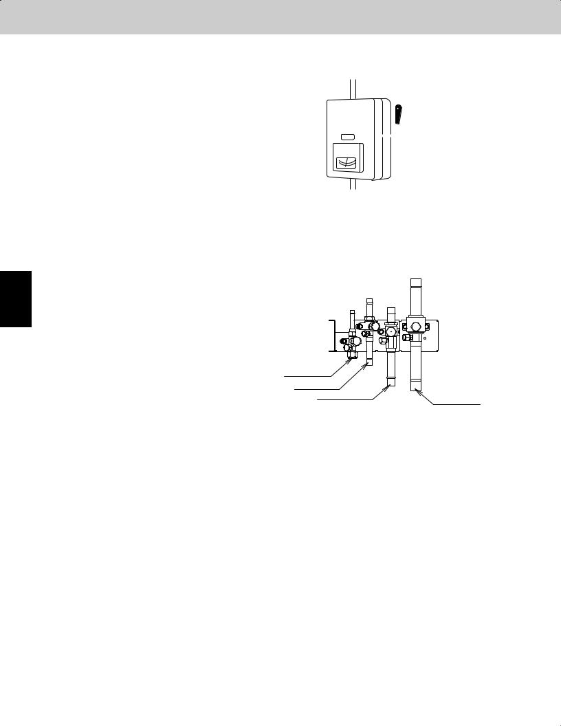
 (Power must be turned ON at least 5 hours before attempting test run)
Power mains switch
Balance tube
Liquid tube
Discharge tube
Suction tube
1 - 2

Test Run
1. Test Run
1-2. Test Run Procedure
Items to Check Before the Test Run
Recheck the items to check before the test run.
<Outdoor unit control PCB> Unit No. setting switch (S007)
<Outdoor unit control PCB> Unit No. setting switch (S006)
<Outdoor unit control PCB> Unit No. setting switch (S004 and S005)
(Check the link wiring.)
<Outdoor unit control PCB> Unit No. setting switch (S002 and S003)
NO
Have the outdoor sub units been connected?
YES
*1
Set the unit address.
Set the No. of outdoor units.
Set the No. of indoor units.
Are the inter-unit control wires |
NO |
connected to more than 1 refrigerant |
|
system? |
|
YES |
|
Set the system address. |
|
1.Turn the remote power switch on at least 5 hours before the test, in order to energize the crankcase heater.
2.After performing the leak inspection, applying vacuum, and performing refrigerant charge for the tubing which is connected onsite, fully open the outdoor unit service valve. However if only one outdoor unit is installed, a balance tube is not used. Therefore, leave the valve fully closed.
3.When replacing the control PCB, be sure that the settings on the new PCB match those on the old PCB.
4.Use caution when making the settings. If there are duplicated system addresses, or if the settings for the Nos. of the indoor units are not consistent, an alarm will occur and the system will not start.
5.These settings are not made on the indoor unit PCB.
CASE 1
|
When multiple outdoor main units exist, disconnect the terminals |
Note: It is not necessary to remove |
|
*1 |
The unit with the unit |
||||||||||||
|
extended from the shorted plugs (CN003) at all outdoor main unit |
|
|
the socket that is used to short- |
|||||||||||||
|
|
|
|
|
No. set to 1 is the |
||||||||||||
|
|
PCBs except for 1. |
|
|
|
|
|
|
circuit the terminal plugs from |
|
|
|
|||||
|
|
|
|
|
|
|
|
|
|
|
main unit. All other |
||||||
|
|
Alternatively, move the sockets to the OPEN side. |
|
|
the outdoor sub unit PCBs. |
|
|
|
|
||||||||
|
|
|
|
|
|
|
|
units are sub units. |
|||||||||
|
|
|
|
|
|
YES |
CASE 2 |
|
|
|
|
||||||
|
|
|
|
|
|
|
|
|
|
||||||||
|
|
Is it possible to turn ON the power only |
|
|
|
|
|
||||||||||
|
|
for the 1 refrigerant system where the |
|
|
|
|
|
|
|
|
|
|
|
|
|||
|
|
test run will be performed? |
|
|
|
|
|
|
|
|
|
|
|
Turn ON the indoor and |
|||
|
|
|
|
|
|
|
|
|
|
|
|
|
|
|
|||
|
|
|
NO |
|
|
|
|
|
|
|
|
|
|
|
outdoor unit power for that |
||
|
|
|
|
|
|
|
|
|
|
|
|
|
|
|
refrigerant system only. |
||
|
|
|
|
|
|
|
|
|
|
|
|
|
|
|
|||
|
|
|
|
|
|
|
|
|
|
|
|
|
|
|
|
|
|
|
|
|
|
|
|
|
|
|
|
|
|
|
|
|
|
|
|
|
|
Will automatic address setting be |
|
|
|
Make necessary corrections. |
|
|
|
|
|
||||||
|
|
|
|
|
Short-circuit the automatic address pin (CN100) |
||||||||||||
|
NO |
performed in Heating mode? |
|
|
|
|
|
|
|
|
|
|
on the outdoor main unit PCB for 1 second or |
||||
|
|
|
|
|
|
|
|
|
|
|
|
|
|
|
longer, then release it. |
||
|
CASE 3B |
|
YES |
CASE 3A |
|
|
Turn OFF the indoor and |
|
|
||||||||
|
|
|
|
|
|
|
|
|
|||||||||
|
|
|
|
|
outdoor unit power. |
|
|
|
|
|
|||||||
|
|
|
|
|
|
|
|
|
|
|
|
|
|
|
|
|
|
Is it OK to start the compressors? |
Is it OK to start the compressors? |
|
|
|
|
|
|
|
|
|
LED 1 and 2 blink alternately |
||||||
|
|
|
Check the alarm contents. |
|
|
|
(about 2 or 3 minutes). |
||||||||||
|
|
|
|
|
|
|
|
|
|
|
|
||||||
|
|
|
|
|
|
|
|
|
|
|
|
|
|
|
|||
|
|
|
|
|
|
|
|
|
|
|
|
|
|
|
|
|
|
|
|
|
|
|
|
|
|
|
|
|
|
|
|
|
|
|
|
Turn ON the indoor and |
Turn ON the indoor and |
|
|
|
|
|
|
|
NO |
|
|
|
|
|
|||
outdoor unit power. |
outdoor unit power. |
|
|
|
|
|
|
|
|
|
Are LED 1 and 2 on the |
||||||
*2 |
|
*2 |
|
|
|
Make necessary |
|
|
|
|
|
|
|
outdoor unit PCB OFF? |
|||
Short-circuit the mode change pin |
|
|
|
corrections |
|
|
Refer to "Table of Self- |
|
|
||||||||
Short-circuit the automatic address |
|
|
|
|
|
|
|
||||||||||
(CN101) on the outdoor main unit PCB. |
pin (CN100) on the outdoor main |
|
|
|
|
Diagnostic Functions and |
|
|
|
|
|
||||||
|
|
|
|
Description of Alarm Displays." |
|
|
YES |
||||||||||
At the same time, short-circuit the |
unit PCB for 1 second or longer, |
|
|
|
|
|
|
|
|||||||||
|
Turn OFF the indoor |
|
|
|
|||||||||||||
automatic address pin (CN100) for 1 |
then release it. |
|
|
|
|
|
|
|
|||||||||
|
|
and outdoor unit |
|
|
|
|
|
||||||||||
second or longer, then release it. |
|
|
|
|
|
|
|
|
|
||||||||
*3 |
|
*3 |
|
|
|
|
Start indoor and outdoor unit |
Start indoor and outdoor unit |
Check the alarm |
||||
cooling operation. |
|
heating operation. |
||||
|
contents. |
|||||
LED 1 and 2 blink alternately. |
LED 1 and 2 blink alternately. |
|||||
|
|
|||||
|
|
|
NO |
|
|
|
|
|
|
|
|||
|
|
|
|
|
||
|
Are LED 1 and 2 on the |
|
|
|||
|
outdoor unit PCB OFF? |
|
|
|
||
YES
Check that test run preparation is OK.
(Do not allow the short-circuited pins to remain short-circuited.)
Set the wired remote controller for test run.
Refer to the remote |
|
|
NO |
Check and make corrections according to |
|
|
|||
controller test-run |
Does system operate? |
|||
settings. |
|
"Table of Self-Diagnostic Functions." |
||
|
|
|
||
|
|
|
|
|
|
|
YES |
|
|
|
|
|
||
|
Return remote control to normal mode |
|
||
|
End test run. |
|
||
*2 A minimum of 5 hours must have passed after the power was turned ON to the outdoor unit.
*3 All indoor units operate in all refrigerant systems where the power is ON.
1
2
3
4
5
6
7
1 - 3

Test Run
2. Setting of Unit Control PCB
2-1. Main Outdoor Unit PCB Setting
1
2
3
4
5
6
S007 S006 S005 S004 S002 S003
7
CN003
CN101
CN100
1 - 4

Test Run
2. Setting of Unit Control PCB
z Examples of the No. of indoor units settings (S005, S004)
No. of indoor units |
Indoor unit setting (S005) |
Indoor unit setting (S004) |
|||
(3P DIP switch, blue) |
(Rotary switch, red) |
||||
|
10 20 30 |
|
|
||
1 unit (factory setting) |
ON |
|
|
ON |
1 |
All OFF |
|
3 |
|
Set to 1 |
|
|
1 |
2 |
OFF |
|
|
|
ON |
|
|
ON |
1 |
11 units |
|
|
|
||
1 ON |
2 |
3 |
|
Set to 1 |
|
|
1 |
OFF |
|
||
21 units |
ON |
|
|
ON |
1 |
2 ON |
2 |
3 |
|
Set to 1 |
|
|
1 |
OFF |
|
||
31 units |
ON |
|
|
ON |
1 |
3 ON |
2 |
3 |
|
Set to 1 |
|
|
1 |
OFF |
|
||
|
ON |
|
|
ON |
0 |
40 units |
1 & 3 ON |
|
|
|
|
2 |
3 |
|
Set to 0 |
||
|
1 |
OFF |
|
||
z Examples of refrigerant circuit (R.C.) address settings (required when link wiring is used) (S003, S002)
System address No. |
System address (S003) |
System address (S002) |
||||
(2P DIP switch, blue) |
||||||
(Rotary switch, black) |
||||||
|
10 20 |
|
||||
|
ON |
|
|
|||
System 1 (factory setting) |
ON |
|
1 |
Set to 1 |
||
Both OFF |
|
|
|
|||
|
1 |
2 |
OFF |
|
|
|
|
ON |
|
ON |
1 |
|
|
System 11 |
1 ON |
|
|
Set to 1 |
||
2 |
|
|
||||
|
1 |
OFF |
|
|
||
System 21 |
ON |
|
ON |
1 |
Set to 1 |
|
2 ON |
2 |
OFF |
|
|||
|
1 |
|
|
|||
System 30 |
ON |
|
ON |
0 |
Set to 0 |
|
1 & 2 ON |
|
|
||||
2 |
|
|
||||
|
1 |
OFF |
|
|
||
z Examples of the No. of outdoor units settings (S006)
No. of outdoor units |
Outdoor unit setting (S006) |
||||
(3P DIP switch, blue) |
|||||
|
|||||
1 unit (factory setting) |
ON |
|
|
ON |
|
1 ON |
|
|
|
||
|
1 |
2 |
3 |
OFF |
|
|
ON |
|
|
ON |
|
2 units |
2 ON |
|
|
|
|
|
1 |
2 |
3 |
OFF |
|
|
ON |
|
|
ON |
|
3 units |
1 & 2 ON |
|
|
|
|
|
1 |
2 |
3 |
OFF |
|
z Address setting of main outdoor unit (S007)
Unit No. setting |
Address setting of outdoor unit (S007) |
||||
(3P DIP switch, blue) |
|||||
|
|||||
Unit No. 1 (main unit) |
ON |
|
|
ON |
|
|
|
|
|
||
(factory setting) |
1 |
2 |
3 |
OFF |
|
|
|||||
z Address setting of sub outdoor unit |
|
|
|
||
Unit No. setting |
Address setting of outdoor unit (S007) |
||||
(3P DIP switch, blue) |
|||||
|
|||||
Unit No. 2 (sub unit) |
ON |
|
|
ON |
|
2 ON |
|
|
|
||
(factory setting) |
|
|
|
||
1 |
2 |
3 |
OFF |
||
Unit No. 3 (sub unit) |
ON |
|
|
ON |
|
1 & 2 ON |
|
|
|
||
|
1 |
2 |
3 |
OFF |
|
The sub unit control PCB contains the same switches as the main unit control PCB for No. of indoor units, No. of outdoor units, and system address. However it is not necessary to set these switches.
1
2
3
4
5
6
7
1 - 5
1
2
3
4
5
6
7
Test Run
3. Auto Address Setting
3-1. Auto Address Setting
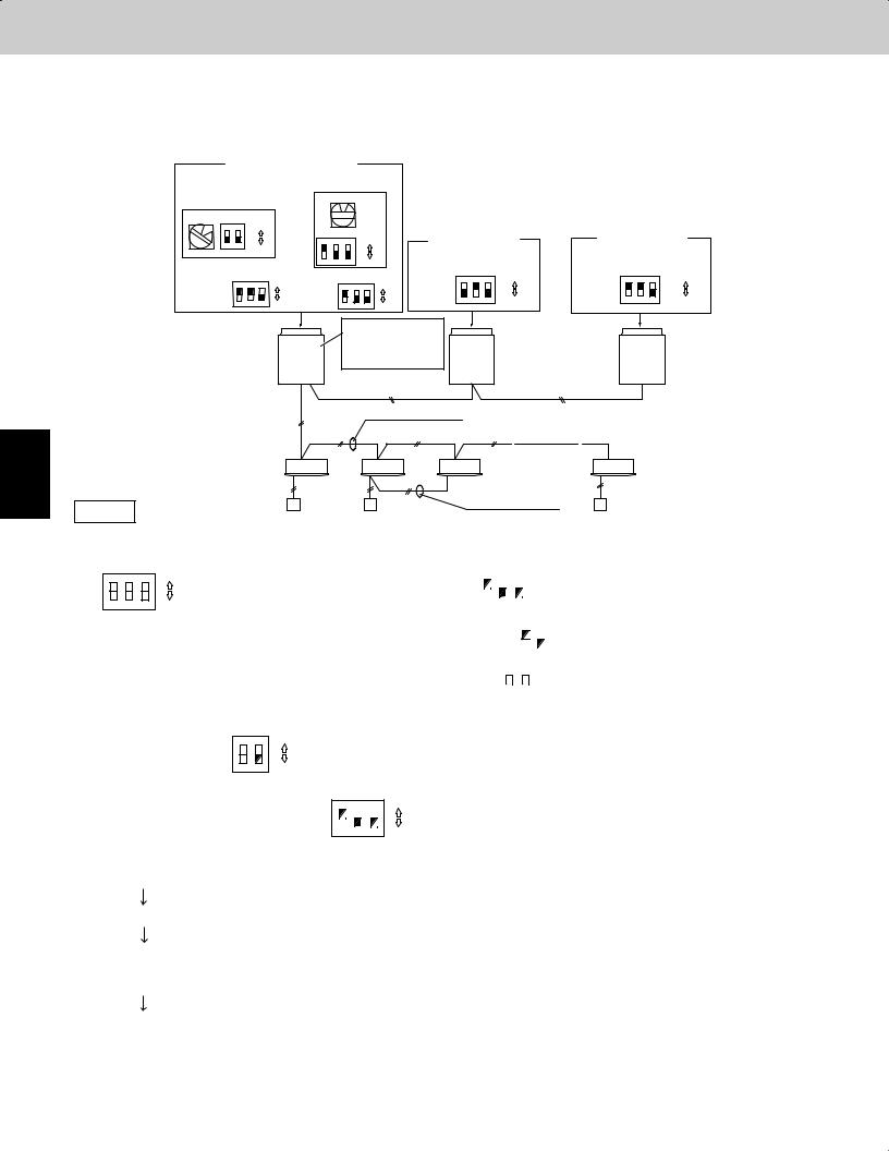
Basic wiring diagram: Example (1)
•If link wiring is not used (The inter-unit control wires are not connected to multiple refrigerant systems.)
Indoor unit addresses can be set without operating the compressors.
No. 1 (main outdoor unit)
|
settings No. of indoor units |
|
System address |
(10 units setting) |
|
(S004) |
||
(system 1 setting) |
||
0 |
(S002) |
(S003) |
|
|
|
|
|
|
|
|
|
|
|
|
|
|
|
|
|
|
|
|
1 |
ON |
|
|
ON |
|
(S005) |
|
|
|
|
|
|
|
|
|
|
|
|
|
||
|
|
|
|
|
|
|
|
|
No. 2 (sub unit) |
No. 3 (sub unit) |
|
||||||||||
|
|
|
|
|
|
|
|
|
|
|
|||||||||||
|
1 |
2 |
|
OFF |
|
ON |
|
|
|
ON |
|
|
|
||||||||
|
|
|
|
|
|
|
|
|
|
|
|
|
|
|
|
|
|
|
|||
No. of |
|
|
|
|
|
1 |
2 |
3 |
|
OFF |
Unit |
|
|
|
|
|
Unit |
|
(S007) |
|
|
|
(S006) |
|
|
|
(S007) |
|
|
(S007) |
|
|
|
ON |
|||||||||
outdoor |
|
ON |
Unit number |
|
number |
|
ON |
|
|
ON |
number |
ON |
|||||||||
|
ON |
|
|
ON |
|
|
ON |
|
|
|
|
|
|
||||||||
units (3 units |
|
|
|
setting |
|
|
|
setting |
|
|
|
|
|
setting |
|
|
|
||||
|
|
|
|
|
|
|
|
|
|
1 |
2 |
3 |
OFF |
1 |
2 3 |
OFF |
|||||
setting) |
|
1 |
2 |
3 |
OFF |
(Unit No. 1) |
|
1 |
2 |
3 |
OFF |
(Unit No. 2) |
(Unit No. 3) |
||||||||
|
|
Leave the socket that |
|
|
|
|
Unit |
is used to short-circuit |
Unit |
|
Unit |
Outdoor Unit |
the terminal plug. |
|
|||
No. 1 |
(CN003) |
No. 2 |
|
No. 3 |
|
|
(Main) |
Outdoor main/sub |
(Sub) |
Outdoor main/sub |
(Sub) |
|
|
|
|
||
|
|
control wiring |
|
control wiring |
|
Inter-unit control wiring
|
Indoor Unit 1-1 |
1-2 |
1-3 |
1-10 |
|
|
|
|
Remote controller |
Case 1 |
Remote controller |
|
|
cross-over wiring |
|
|
|
|
(1) Automatic Address Setting from the Outdoor Unit
1.To set the number of outdoor units, on the outdoor main unit control PCB set the No. of outdoor units DIP switch (S006) to
ON |
|
ON |
|
ON |
|
|
|
|
|
|
|
|
|
|
||||||
|
|
|
|
|
|
|
(3 units), and set the unit No. DIP switch (S007) to |
|
|
|
|
|
|
|
|
|
(unit No. 1 - main outdoor unit). |
|||
|
1 2 3 OFF |
|
|
1 |
|
2 |
|
|
3 |
|
|
|
|
|
||||||
|
|
|
|
|
|
|
|
|
|
|
|
|
|
|
||||||
|
|
|
|
|
|
|
|
|
|
|
|
|
|
|
|
|
|
|
|
|
|
|
|
|
|
|
|
|
|
|
|
|
ON |
|
|
|
|
||||
2. On the No. 2 (sub) unit control PCB, set the unit No. switch (S007) to |
|
|
|
|
|
|
|
|
|
(unit No. 2). |
||||||||||
|
|
|
|
|
|
|
|
|
||||||||||||
|
|
|
|
|
|
|
|
|
|
|
|
|
1 |
|
2 |
|
3 |
|
|
|
|
|
|
|
|
|
|
|
|
|
|
|
|
|
|
|
|
|
|
|
|
|
|
|
|
|
|
|
|
|
|
|
|
ON |
|
|
|
|
||||
On the No. 3 (sub) unit control PCB, set the unit No. switch (S007) to |
|
|
|
|
|
|
|
|
|
(unit No. 3). |
||||||||||
|
|
|
|
|
|
|
|
|
||||||||||||
|
|
|
|
|
|
|
|
|
|
|
|
1 |
|
2 |
|
3 |
|
|
||
3.On the outdoor main unit control PCB, check that the system address rotary switch (S002) is set to “1” and that the DIP
ON ON
switch (S003) is set to |
|
|
|
“0.” (These are the settings at the time of factory shipment.) |
|
|
|
1 2 OFF
4.To set the number of indoor units that are connected to the outdoor unit to 10, on the outdoor main unit control PCB set the
ON ON
No. of indoor units DIP switch (S005) to |
|
|
|
|
|
“1.” and set the rotary switch (S004) to “0.” |
|
|
|
|
|
1 2 3 OFF
5.Turn ON the power to the indoor and outdoor units.
6.On the outdoor main unit control PCB, short-circuit the automatic address pin (CN100) for 1 second or longer, then release it.
(Communication for automatic address setting begins.)
*To cancel, again short-circuit the automatic address pin (CN100) for 1 second or longer, then release it. The LED that indicates that automatic address setting is in progress turns OFF and the process is stopped.
Be sure to perform automatic address setting again.
(Automatic address setting is completed when LEDs 1 and 2 on the outdoor main unit control PCB turn OFF.)
7.Operation from the remote controllers is now possible.
*To perform automatic address setting from the remote controller, perform steps 1 to 5, then use the remote controller and
complete automatic address setting.
z Refer to “Automatic Address Setting from the Remote Controller.”
1 - 6
Test Run
3. Auto Address Setting
Basic wiring diagram: Example (2)
|
• If link wiring is used |
* When multiple outdoor main units exist, remove the socket that is |
|
No. 1 (main outdoor unit) settings |
used to short-circuit the terminal plug (CN003) from all outdoor |
||
main unit PCBs except for one unit. |
|||
|
No. of indoor units |
||
System address |
Alternatively, move the sockets to the “OPEN” side. |
||
(system 1 setting) |
(13 units setting) |
|
|
(S002) |
(S003) |
|
(S004) |
|
|
ON |
|
|
|||
1 |
ON |
|
|
|
|
|
1 |
2 |
OFF |
(S005) |
ON |
|
|
|
|||
|
|
|
|
ON |
|
|
|
|
|
1 |
2 |
3 |
OFF |
|
|
No. 2 (sub unit) |
|
||
|
|
|
|
|
|
|
|
|
|
||||
No. of |
|
(S006) |
Unit |
|
|
(S007) |
|
Unit |
|
|
|
||
|
|
|
|
|
|
(S007) |
|
||||||
outdoor units ON |
|
ON number |
|
ON |
|
ON |
|
ON |
|||||
|
|
|
number |
|
|
||||||||
(3 units |
|
|
|
setting |
|
|
|
|
ON |
||||
setting) |
|
2 |
3 |
|
|
|
|
setting |
|
|
|
||
1 |
OFF (unit No. 1) |
1 2 |
3 |
OFF |
|
|
OFF |
||||||
|
|
|
|
|
|
|
|
|
|
(unit No. 2) |
1 |
2 3 |
|
No. 3 (sub unit)
Unit |
(S007) |
ON |
|
number |
|||
ON |
|||
setting |
|
|
|
(unit No. 3) |
1 2 3 |
OFF |
Outdoor unit |
Unit |
Leave the socket that |
Unit |
|
Unit |
|
is used to short-circuit |
|
|||||
No. 1 |
No. 2 |
|
No. 3 |
|||
system 1 |
|
|||||
the terminal plug. |
|
|||||
(Main) |
(Sub) |
Outdoor main/sub |
(Sub) |
|||
|
||||||
|
(CN003) |
|||||
|
|
|
control wiring |
|
||
|
|
|
|
|
Inter-unit control wiring
|
Indoor unit |
|
1-1 |
1-2 |
1-3 |
1-13 |
|
|
Remote |
|
|
|
Remote controller |
||
|
|
|
|
communication |
wiring |
||
|
controller |
|
|
|
|||
|
|
|
|
|
|
||
No. 2 |
|
|
No. 1 (main unit) settings |
|
|
||
Refrigerant |
System address |
No. of indoor units |
|
||||
circuit |
(system 2 setting) |
(9 units setting) |
|
||||
|
(S002) |
(S003) |
|
(S004) |
|
|
|
|
ON |
|
|
|
|||
|
|
ON |
|
9 |
|
|
|
|
2 |
|
|
|
|
|
|
|
|
1 |
2 |
OFF |
(S005) |
|
|
|
|
|
|
ON |
|
||
|
|
|
|
|
ON |
|
|
|
|
|
|
|
1 |
2 3 |
OFF |
|
|
No. 2 (sub unit) settings |
|||
|
|
|
|
|
|
|
Unit |
|
|
|
|||
No. of |
|
(S006) |
|
Unit |
|
(S007) |
|
|
(S007) |
ON |
|||
outdoor |
|
|
|
ON |
number |
ON |
number |
ON |
|||||
ON |
|
ON |
|
|
|||||||||
units (2 units |
|
|
|
|
setting |
|
|
|
setting |
|
|
|
|
setting) |
1 |
2 |
3 |
OFF (unit No. 1) |
1 2 |
3 |
OFF |
(unit No. 2) |
1 |
2 3 |
OFF |
||
Outdoor unit |
Unit |
No. 1 |
|
system 2 |
(Main) |
Indoor unit 2-1
To other system
link wiring
Remote controller
Move the socket to |
Unit |
the “OPEN”side |
No. 2 |
(CN003). |
(Sub) |
|
Outdoor main/sub control wiring |
Inter-unit control wiring
2-2 2-9
Remote controller cross-over wiring
Make settings as appropriate for the cases listed below. (Refer to the instructions on the following pages.)
· Indoor and outdoor unit power can be turned ON for each system separately. |
Case 2 |
· Indoor and outdoor unit power cannot be turned ON for each system separately. |
|
Automatic address setting in Heating mode |
Case 3A |
Automatic address setting in Cooling mode |
Case 3B |
1
2
3
4
5
6
7
1 - 7

1
2
3
4
5
6
7
Test Run
3. Auto Address Setting
Case 2 Automatic Address Setting (no compressor operation)
zIndoor and outdoor unit power can be turned ON for each system separately. Indoor unit addresses can be set without operating the compressors.
Automatic Address Setting from Outdoor Unit
|
|
|
|
|
ON |
|
|
|
|
|
|
||
1. On the No. 1 |
(main) unit control PCB, set the unit No. switch (S007) to |
|
|
|
|
|
|
|
|
(unit No. 1). |
|||
|
|
|
|
|
|
|
|
||||||
|
|
|
|
|
|
1 |
|
2 |
|
|
3 |
|
|
|
|
|
|
|
|
|
|
|
|
|
|
|
|
|
|
ON |
|
|
|
|
|
|
|
||||
On the No. 2 |
(sub) unit control PCB, set the unit No. switch (S007) to |
|
|
|
|
|
|
|
|
|
|
(unit No. 2). |
|
|
|
|
|
|
|
|
|
|
|
||||
|
|
|
|
1 |
|
2 |
|
3 |
|
|
|
|
|
|
|
|
|
|
|
|
|
|
|
||||
On the No. 3 |
(sub) unit control PCB, set the unit No. switch (S007) to |
ON |
|
|
|
|
|
(unit No. 3). |
|||||
|
|
|
|
|
|
|
|
|
|
||||
|
|
|
|
|
|
|
|
|
|
|
|
|
|
|
|
|
|
1 |
|
2 |
|
3 |
|
|
|
|
|
2.To set the number of outdoor units on the outdoor main unit control PCB, set the No. of outdoor units DIP switch (S006) to
ON ON
(3 units).
1 2 3 OFF
3.On the outdoor main unit control PCB, check that the system address rotary switch (S002) is set to “1” and that the DIP
|
ON |
ON |
switch (S003) is set to “0” |
|
. (These are the settings at the time of factory shipment.) |
1 2 OFF
4.To set the number of indoor units that are connected to the outdoor unit to 13, on the outdoor main unit control PCB set the
ON ON
No. of indoor units DIP switch (S005) to “1” |
|
|
|
|
|
, and set the rotary switch (S004) to “3.” |
|
|
|
|
|
1 2 3 OFF
5.Turn on power to all indoor and outdoor units in the system.
6.Short-circuit the automatic address pin at the outdoor main unit (CN100) for 1 second or longer, then release it.
(Communication for automatic address setting begins.)
*To cancel, again short-circuit the automatic address pin (CN100) for 1 second or longer, then release it. The LED that indicates automatic address setting is in progress turns OFF and the process is stopped. Be sure to perform automatic address setting again.
(Automatic address setting is completed when LEDs 1 and 2 on the outdoor main unit control PCB turn OFF.)
7.Next turn the power ON only for the indoor and outdoor units of the next (different) system. Repeat steps 1 - 5 in the same way to complete automatic address settings for all systems.
8.Operation from the remote controllers is now possible.
*To perform automatic address setting from the remote controller, perform steps 1 - 5, then use the remote controller and complete automatic address setting.
z Refer to “Automatic Address Setting from Remote Controller.”
1 - 8

Test Run
3. Auto Address Setting
Case 3A Automatic Address Setting in Heating Mode
zIndoor and outdoor unit power cannot be turned ON for each system separately.
In the following, automatic setting of indoor unit addresses is not possible if the compressors are not operating. Therefore perform this process only after completing all refrigerant tubing work.
Automatic Address Setting from Outdoor Unit
1.Perform steps 1 - 4 in the same way as for Case 2 .
5.Turn the indoor and outdoor unit power ON at all systems.
6.To perform automatic address setting in Heating mode , on the outdoor main unit control PCB in the refrigerant system where you wish to set the addresses, short-circuit the automatic address pin (CN100) for 1 second or longer, then release it. (Be sure to perform this process for one system at a time. Automatic address settings cannot be performed for more than one system at the same time.)
(Communication for automatic address setting begins, the compressors turn ON, and automatic address setting in Heating mode begins.)
(All indoor units operate.)
*To cancel, again short-circuit the automatic address pin (CN100) for 1 second or longer, then release it. The
LED that indicates automatic address setting is in progress turns OFF and the process is stopped. Be sure to perform automatic address setting again.
(Automatic address setting is completed when the compressors stop and LED 1 and 2 on the main unit control PCB turn OFF.)
7.At the outdoor main unit in the next (different) system, short-circuit the automatic address pin (CN100) for 1 second or
longer, then release it.
(Repeat the same steps to complete automatic address setting for all units.)
8.Operation from the remote controllers is now possible.
*To perform automatic address setting from the remote controller, perform steps 1 - 5, then use the remote controller and to complete automatic address setting.
z Refer to “Automatic Address Setting from Remote Controller.”
1
2
3
4
5
6
7
1 - 9
Test Run
3. Auto Address Setting
|
|
Case 3B |
Automatic Address Setting in Cooling Mode |
|||||
|
|
|
|
|||||
|
|
z Indoor and outdoor unit power cannot be turned ON for each system separately. In the following, automatic setting of indoor |
||||||
|
|
|
unit addresses is not possible if the compressors are not operating. Therefore perform this process only after completing all |
|||||
|
|
|
refrigerant tubing work. |
|||||
|
|
|
Automatic address setting can be performed during Cooling operation. |
|||||
|
|
Automatic Address Setting from Outdoor Unit |
||||||
|
|
|
|
|
|
|
|
|
|
1. |
Perform steps 1 - 4 in the same way as for |
Case 2 |
. |
|
|||
|
|
5. Turn the indoor and outdoor unit power ON at all systems. |
||||||
|
|
|
|
|
|
|
||
|
6. |
To perform automatic address setting in |
Cooling mode |
, on the outdoor main unit control PCB in the refrigerant system |
||||
|
|
|
where you wish to set the addresses, short-circuit the mode change 2P pin (CN101). At the same time, short-circuit the |
|||||
|
|
|
automatic address pin (CN100) for 1 second or longer, then release it. (Be sure to perform this process for one system at a |
|||||
|
|
|
time. Automatic address settings cannot be performed for more than one system at the same time.) |
|||||
|
|
|
(Communication for automatic address setting begins, the compressors turn ON, and automatic address setting in Cooling |
|||||
|
|
|
mode begins.) |
|||||
|
|
|
(All indoor units operate.) |
|||||
1 |
|
|
|
* To cancel, again short-circuit the automatic address pin (CN100) for 1 second or longer, then release it. The |
||||
|
|
|
LED that indicates automatic address setting is in progress turns OFF and the process is stopped. Be sure to |
|||||
|
|
|
perform automatic address setting again. |
|||||
|
|
|
|
|||||
|
|
|
(Automatic address setting is completed when the compressors stop and LED 1 and 2 on the outdoor main unit control PCB |
|||||
|
|
|
turn OFF.) |
|||||
2 |
|
|
||||||
|
7. At the outdoor main unit in the next (different) system, short-circuit the automatic address pin (CN100) for 1 second or |
|||||||
|
|
|||||||
|
|
|
longer, then release it. |
|||||
|
|
|
(Repeat the same steps to complete automatic address setting for all units.) |
|||||
|
|
|
||||||
3 |
|
8. Operation from the remote controllers is now possible. |
||||||
|
|
* Automatic address setting in Cooling mode cannot be done from the remote controller. |
||||||
4
5
6
7
Automatic Address Setting* from the Remote Controller
Selecting each refrigerant system individually for automatic address setting
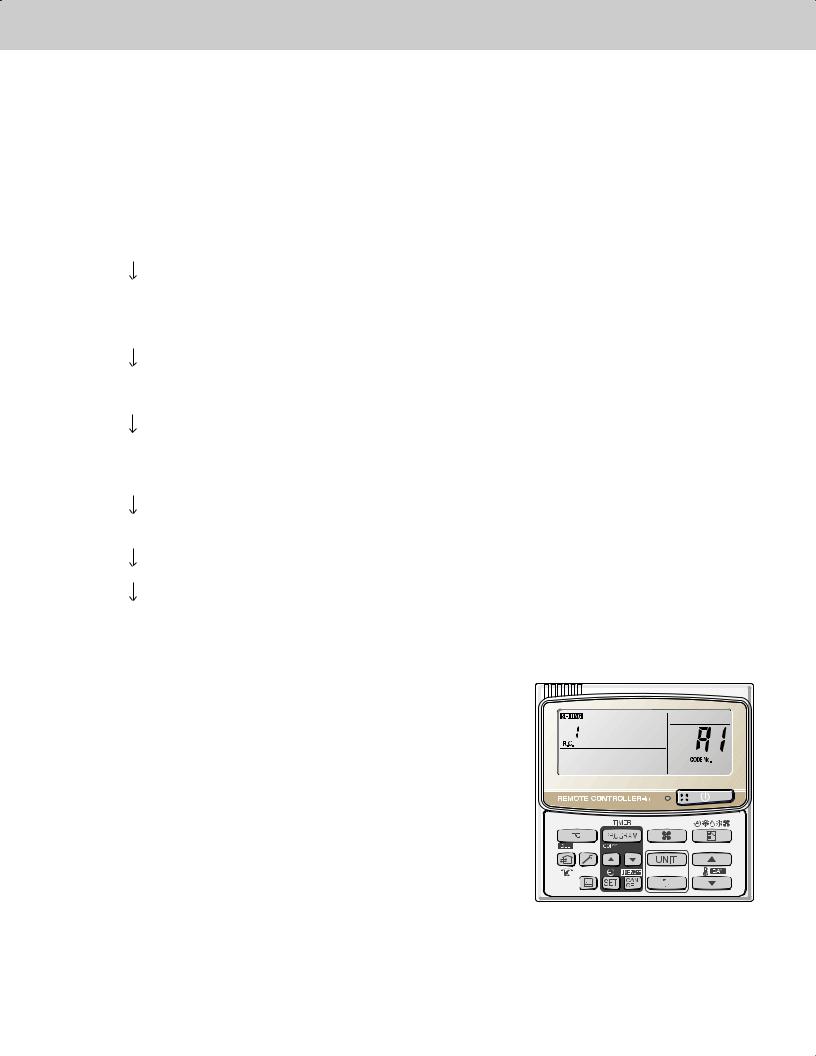
---Automatic address setting for each system: Item code “A1.”
1. Press the remote controller timer time  button and
  button at the same time.
(Press and hold for 4 seconds or longer.)
2. Next, press either the temperature setting  or
or  button. (Check that the item code is “A1.”)
3. Use either the  or
or  button to set the system No. to perform automatic address setting.
4. Then press the  button.
(Automatic address setting for one refrigerant system begins.)
(When automatic address setting for one system is completed, the system returns to normal stopped status.) <Approximately 4 - 5 minutes is required.>
(During automatic address setting, “NOW SETTING” is displayed on the remote controller. This message disappears when automatic address setting is completed.)
5.Repeat the same steps to perform automatic address setting for each successive system.
1 - 10

Test Run
3. Auto Address Setting
Display during automatic address setting
z On outdoor main unit PCB
LED 2 1
*Do not short-circuit the automatic address setting pin (CN100) again while automatic address setting is in progress. Doing so will cancel the setting operation and will cause LED 1 and 2 to turn OFF.
Blink alternately
*When automatic address setting has been successfully completed, both LED 1 and 2 turn OFF.
*LED 1 is D72. LED 2 is D75.
*If automatic address setting is not completed successfully, refer to the table below and correct the problem. Then perform automatic address setting again.
z Display of LED 1 and 2 on the outdoor unit control PCB
( : ON
: ON  : Blinking
  :OFF)
:OFF)
LED1 |
LED2 |
Display meaning |
After the power is turned ON (and automatic address setting is not in progress), no communication with the indoor units in that system is possible.
After the power is turned ON (and automatic address setting is not in progress), 1 or more indoor units are confi rmed in that system; however, the number of indoor units does not match the number that was set.
Automatic address setting is in progress.
Alternating
Automatic address setting completed.
|
At time of automatic address setting, the number of indoor units did not match the number that was set. |
Simultaneous |
“ ”(when indoor units are operating) indication appears on the display. |


 Refer to “Table of Self-Diagnostic Functions and Description of Alarm Displays.”
Alternating
NOTE
“ ” indicates that the solenoid is fused or that there is a CT detection current failure (current is detected when the compressor is OFF).
z Remote controller display
 is blinking
1
2
3
4
5
6
7
1 - 11

3.Auto Address Setting
4.Remote Controller Test Run Settings
Test Run
Request concerning recording the indoor/outdoor unit combination Nos.
After automatic address setting has been completed, be sure to record them for future reference.
List the outdoor main unit system address and the addresses of the indoor units in that system in an easily visible location (next to the nameplate), using a permanent marking pen or similar means that cannot be abraded easily.
Example: (Outdoor) 1 - (Indoor) 1-1, 1-2, 1-3… (Outdoor) 2 - (Indoor) 2-1, 2-2, 2-3…
These numbers are necessary for later maintenance. Please be sure to indicate them.
Checking the indoor unit addresses
Use the remote controller to check the indoor unit address.
<If 1 indoor unit is connected to 1 remote controller>
1.Press and hold the  button and
  button for 4 seconds or longer (simple settings mode).
2.The address is displayed for the indoor unit that is connected to the remote controller.
(Only the address of the indoor unit that is connected to the remote controller can be checked.)
3.Press the  button again to return to normal remote controller mode.
<If multiple indoor units are connected to 1 remote controller (group control)>
1.Press and hold the  button and
  button for 4 seconds or longer (simple settings mode).
2.“ALL” is displayed on the remote controller.
3.Next, press the  button.
4.The address is displayed for 1 of the indoor units which is connected to the remote controller. Check that the fan of that indoor unit starts and that air is discharged.
15. Press the  button again and check the address of each indoor unit in sequence.
6.Press the  button again to return to normal remote controller mode.
2
3
Number changes to indicate which indoor unit is currently selected.
4
5
4. Remote Controller Test Run Settings
1.Press the remote controller  button for 4 seconds or longer. Then press the
  button.
“TEST RUN” appears on the LCD display while the test run is in progress.
The temperature cannot be adjusted when in Test Run mode.
(This mode places a heavy load on the machines. Therefore use it only when performing the test run.) 2. The test run can be performed using the HEAT, COOL, or FAN operation modes.
NOTE
The outdoor units will not operate for approximately 3 minutes after the power is turned ON and after operation is stopped.
3.If correct operation is not possible, a code is displayed on the remote controller LCD display. (Refer to “Table of Self-Diagnostic Functions” and correct the problem.)
6 |
4. |
After the test run is completed, press the |
button again. Check that “TEST RUN” disappears from the LCD display. (To |
|
prevent continuous test runs, this remote controller includes a timer function that cancels the test run after 60 minutes.) |
||
*If the test run is performed using the wired remote controller, operation is possible even if the cassette-type ceiling panel has not been installed. (“P09” display does not occur.)
7
1 - 12

Test Run
5. Caution for Pump Down
5. Caution for Pump Down
Pump down means refrigerant gas in the system is returned to the outdoor unit. Pump down is used when the unit is to be moved, or before servicing the refrigerant circuit.
 This outdoor unit cannot collect more than the rated refrigerant amount as
CAUTION shown by the nameplate on the back.  If the amount of refrigerant is more than that recommended, do not conduct pump down. In this case use another refrigerant collecting system.
1
2
3
4
5
6
7
1 - 13

1
2
3
4
5
6
7
Test Run
6. Meaning of Alarm Messages
6. Meaning of Alarm Messages
Table of Self-Diagnostics Functions and Description of Alarm Displays
Alarm messages are indicated by the blinking of LED 1 and 2 (D72, D75) on the outdoor unit PCB. They are also displayed on the wired remote controller.
z Viewing the LED 1 and 2 (D72 and D75) alarm displays
LED1 |
LED2 |
Alarm contents |
|
|
|
|
|
Alarm Display |
Alternating |
LED 1 blinks M times, then LED 2 blinks N times. The cycle then repeats. |
|
|
|
M = 2: P alarm 3: H alarm 4: E alarm 5: F alarm 6: L alarm |
|
|
N = Alarm No. |
|
|
Example: LED 1 blinks 2 times, then LED 2 blinks 17 times. The cycle then repeats. |
|
|
Alarm is "P17". |
( : Blinling) Connect the outdoor maintenance remote controller to the RC socket on the outdoor main unit control PCB (3P, blue),and check the Alarm Messages on the remote controller display.
Possible cause of malfunction |
Alarm |
|
Message |
||
|
Serial |
Remote controller is |
Error in receiving serial communication signal. |
<E01> |
|
communication |
detecting error signal from |
(Auto address is not completed.) |
||
|
||||
errors |
indoor unit. |
|
|
|
Error in transmitting serial communication signal. |
<E02> |
|||
Mis-setting |
|
|||
|
|
|
||
Indoor unit is detecting error signal from remote controller and system controller. |
<<E03>> |
|||
|
||||
|
|
|
|
|
|
Indoor unit is detecting error |
Group wiring failure of indoor units in the refrigerant system |
|
|
|
(occurring when remote controller is operated immediately after |
E04 |
||
|
signal from outdoor unit. |
|||
|
automatic address setting) |
|
||
|
|
|
||
|
|
|
|
|
|
Outdoor unit is detecting error |
Error in receiving serial communication signal. |
|
|
|
signal from indoor unit. |
There is an indoor unit which does not send signals when the |
E06 |
|
|
|
power is ON. |
|
|
|
|
|
|
|
|
Improper setting |
Indoor unit address setting is duplicated. |
<<E08>> |
|
|
|
|
||
|
Duplicated remote controller "main" setting. |
<<E09>> |
||
|
|
|||
|
|
|
|
|
|
|
Starting auto. address setting is prohibited. |
E12 |
|
|
|
AP pin / CN102 is shorted while the auto. address setting started. |
||
|
|
|
||
|
|
|
|
|
|
Indoor unit communication |
Error of main indoor unit in receiving serial communication signal |
E18 |
|
|
error of group control wiring. |
from sub indoor units. |
||
|
|
|||
|
|
|
|
|
|
During auto. address setting, |
Number of connected indoor units is less than the number set. |
E15 |
|
|
number of connected units |
|
|
|
|
Number of connected indoor units is more than the number set. |
E16 |
||
|
does not correspond to |
|||
|
|
|
||
|
No indoor unit is connected. |
E20 |
||
|
number set. |
|||
|
|
|
||
|
|
Main outdoor unit is detecting error signal from sub outdoor unit. |
E24 |
|
|
|
|
|
|
|
|
Duplicated outdoor unit address setting. |
E25 |
|
|
|
|
|
|
|
|
Mismatch in "No. of outdoor units" setting. |
E26 |
|
|
|
|
|
|
|
|
Error of sub outdoor unit in receiving signal from main outdoor unit. |
E29 |
|
|
|
|
|
|
|
Improper setting |
Connected indoor unit is not a multi unit. |
<<L02>> |
|
|
|
|
|
|
|
|
Duplication of main indoor unit address setting in group control. |
<L03> |
|
|
|
|
|
|
|
|
Group control wiring is connected to individual control indoor unit. |
L07 |
|
|
|
|
|
|
|
|
Indoor unit address is not set. |
L08 |
|
|
|
|
|
|
|
|
Capacity code of indoor unit is not set. |
<<L09>> |
|
|
|
|
|
|
|
|
Duplication of outdoor system address setting. |
L04 |
|
|
|
|
|
|
|
|
Capacity code of outdoor unit is not set. |
L10 |
|
|
|
|
|
|
|
|
Mismatch of outdoor unit type. |
L17 |
|
|
|
|
|
|
Thermistor |
Indoor unit |
Indoor coil temp. sensor (E1) |
<<F01>> |
|
fault |
|
|
|
|
|
Indoor coil temp. sensor (E3) |
<<F03>> |
||
|
|
|||
|
|
|
|
|
|
|
Indoor suction air (room) temp. sensor (TA) |
<<F10>> |
|
|
|
|
|
|
|
|
Indoor discharge air temp. sensor (BL) |
<<F11>> |
|
|
|
|
|
|
Continued
1 - 14

6. Meaning of Alarm Messages |
Test Run |
|||
|
||||
|
|
|
|
|
Possible cause of malfunction |
|
Alarm |
||
|
Message |
|||
|
|
|
||
Activation of |
Protective device in indoor unit |
Thermal protector in indoor unit fan motor is activated. |
<<P01>> |
|
protective |
is activated. |
|
|
|
Improper wiring connections of ceiling panel. |
<<P09>> |
|||
device |
|
|||
|
|
|
||
|
|
Float switch is activated. |
<<P10>> |
|
|
|
|
|
|
|
|
Operation of protective function of fan inverter. |
P12 |
|
|
|
|
|
|
|
|
O2 sensor (detects low oxygen level) activated. |
P14 |
|
|
|
Incorrect discharge temperature. (Comp. No. 1 (INV)) |
P03 |
|
|
|
|
|
|
|
|
High pressure switch is activated. |
P04 |
|
|
|
|
|
|
|
|
Negtive (defective) phase. |
P05 |
|
|
|
|
|
|
|
|
Compressor running failure resulting from missing phase in the |
P16 |
|
|
|
compressor wiring, etc. (Start failure not caused by IPM or no gas.) |
||
|
|
|
||
|
|
Incorrect discharge temperature. (Comp. No. 2 (constant speed)) |
P17 |
|
|
|
|
|
|
|
|
Outdoor unit fan motor is unusual. |
P22 |
|
|
|
|
|
|
|
|
Overcurrent at time of compressor runs more than 80Hz (DCCT |
|
|
|
|
secondary current or ACCT primary current is detected at a time other |
P26 |
|
|
|
than when IPM has tripped.) |
|
|
|
|
IPM trip (IPM current or temperature) |
H31 |
|
|
|
|
|
|
|
|
Inverter for compressor is unusual. (DC compressor does not operate.) |
P29 |
|
Thermistor fault |
Indoor thermistor is either open |
Indoor coil temp. sensor (E1) |
<<F01>> |
|
|
or damaged. |
|
|
|
|
Indoor coil temp. sensor (E3) |
<<F03>> |
||
|
|
|||
|
|
|
|
|
|
|
Indoor suction air (room) temp. sensor (TA) |
<<F10>> |
|
|
|
|
|
|
|
|
Indoor discharge air temp. sensor (BL) |
<<F11>> |
|
|
|
|
|
|
|
Outdoor thermistor is either |
Comp. No. 1 (INV) discharge gas temp. sensor (DISCH1) |
F04 |
|
|
open or damaged. |
|
|
|
|
Comp. No. 2 (constant speed) discharge gas temp. sensor (DISCH2) |
F05 |
||
|
|
|||
|
|
|
|
|
|
|
Outdoor No. 1 coil gas temp. sensor (EXG1) |
F06 |
|
|
|
Outdoor No. 1 coil liquid temp. sensor (EXL1) |
F07 |
|
|
|
|
|
|
|
|
Outdoor air temp. sensor (AIR TEMP) |
F08 |
|
|
|
|
|
|
|
|
Compressor suction temp. sensor (SCT) |
F12 |
|
|
|
|
|
|
|
|
High pressure sensor. |
F16 |
|
|
|
|
|
|
|
|
Low-pressure sensor failure |
F17 |
|
|
|
|
|
|
|
|
Outdoor No. 2 coil gas temp. sensor (EXG2) |
F23 |
|
|
|
|
|
|
|
|
Outdoor No. 2 coil liquid temp. sensor (EXL2) |
F24 |
|
|
|
|
|
|
EEPROM on indoor unit PCB failure |
|
F29 |
||
|
|
|
|
|
Protective |
Protective device for |
EEPROM on the main or sub outdoor unit PCB has failed. |
F31 |
|
device for |
compressor No.1 (INV) is |
|
|
|
Current is not detected when comp. No. 1 (INV) is ON. |
H03 |
|||
compressor is |
activated. |
|||
activated |
|
|
|
|
Protective device for |
Overload current is detected. |
H11 |
||
|
||||
|
compressor No.2 (constant |
|
|
|
|
Lock current is detected. |
H12 |
||
|
speed) is activated |
|||
|
|
|
||
|
|
Current is not detected when comp. No.2 (constant speed) is ON. |
H13 |
|
|
|
|
|
|
|
|
Discharge gas temperture of comp. No.2 (constant speed) is not |
H15 |
|
|
|
detected. |
||
|
|
|
||
|
|
Low pressure trouble |
H06 |
|
|
|
|
|
|
|
Low oil level alarm. |
|
H07 |
|
|
|
|
|
|
|
Oil sensor fault. |
Comp. No.1 (INV) oil sensor |
H08 |
|
|
(Disconnection, etc.) |
|
|
|
|
Comp. No.2 (constant speed) oil sensor |
H27 |
||
|
|
|||
|
|
|
|
|
Continued
1
2
3
4
5
6
7
1 - 15

6. Meaning of Alarm Messages |
Test Run |
||||
|
|
||||
|
|
|
|
|
|
|
Alarm messages displayed on system controller |
|
|
||
|
|
|
|
|
|
|
Serial |
Error in transmitting serial |
Indoor or main outdoor unit is not oparating correctly. |
|
|
|
communication |
communication signal |
Mis-wiring of control wiring between indoor unit, main outdoor unit and |
C05 |
|
|
errors |
|
system controller. |
|
|
|
Mis-setting |
|
|
|
|
|
Error in receiving serial |
Indoor or main outdoor unit is not operating correctly. |
|
|
|
|
|
|
|
||
|
|
communication signal |
Mis-wiring of control wiring between indoor unit, main outdoor unit and |
C06 |
|
|
|
|
system controller. |
|
|
|
|
|
|
|
|
|
|
|
CN1 is not connected properly. |
|
|
|
|
|
|
|
|
|
Activation of |
Protective device of sub indoor |
When using wireless remote controller or system controller, in order to |
|
|
|
protective |
unit in group control is activated |
check the alarm message in detail, connect wired remote controller to |
P30 |
|
|
device |
|
indoor unit temporarily. |
|
|
|
|
|
|
|
|
NOTE
1.Alarm messages in << >> do not affect other indoor unit operations.
2.Alarm messages in < > sometimes affect other indoor unit operations depending on the fault.
1
2
3
4
5
6
7
1 - 16
Contents |
|
TENTATIVE |
|
Remote Control Functions |
|
|
|
||
2. REMOTE CONTROL FUNCTIONS |
|
|||
1. Main Operating Functions ................................................................................................. |
|
|
2-2 |
|
1-1. Room Temperature Control ........................................................................................... |
2-2 |
|||
1-2. Automatic Control for Heating and Cooling ................................................................... |
2-3 |
|||
2. Wireless Remote Controller |
.............................................................................................. |
|
2-4 |
|
2-1. How to Use the Wireless Remote Controller ................................................................. |
2-4 |
|||
2-2. Receiver ........................................................................................................................ |
|
|
2-7 |
|
2-3. Operation....................................................................................................................... |
|
|
2-8 |
|
2-4. Using the Wireless Remote Control Unit....................................................................... |
2-9 |
|||
2-5. Address Settings ......................................................................................................... |
|
|
2-10 |
|
2-6. Emergency Operation ................................................................................................. |
|
|
2-12 |
|
2-7. Trouble Diagnosis ........................................................................................................ |
|
|
2-14 |
|
3. Timer Remote Controller ................................................................................................. |
|
|
2-15 |
|
3-1. How to Use the Timer Remote Controller.................................................................... |
2-15 |
|||
3-2. Names and Operations ............................................................................................... |
|
|
2-16 |
|
3-3. Installation Manual for Timer Remote Controller ......................................................... |
2-18 |
|||
3-4. How to Install the Remote Controller........................................................................... |
2-18 |
|||
3-5. Group Control Using 2 Remote Controllers................................................................. |
2-19 |
|||
3-6. Remote Controller Setting Mode................................................................................. |
2-19 |
|||
3-7. Indoor Unit Setting Mode............................................................................................. |
|
|
2-19 |
|
3-8. To Display the Sensor Temperature............................................................................. |
2-19 |
|||
3-9. To Display the Trouble History ..................................................................................... |
2-19 |
|||
3-10. Setting the Present Time........................................................................................... |
2-21 |
|||
3-11. Weekly Program Function ......................................................................................... |
2-22 |
|||
3-12. Outing Function......................................................................................................... |
|
|
2-27 |
|
3-13. Sleeping Function...................................................................................................... |
|
|
2-29 |
|
3-14. Wired Remote Controller Test Run Settings.............................................................. |
2-30 |
|||
3-15. Simple Settings Function........................................................................................... |
2-31 |
|||
3-16. Detailed Settings Function ........................................................................................ |
2-33 |
|||
3-17. Remote Controller Servicing Functions..................................................................... |
2-40 |
|||
1
2
3
4
5
6
7
2 - 1
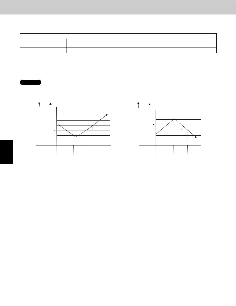
1
2
3
4
5
6
7
Remote Control Functions
1. Main Operating Functions
1-1. Room Temperature Control
The thermostat is turned ON/OFF according to  T as shown below.
 T = Room temperature - Set temperature
When remote controller sensor
Room temperature = Temperature detected by the remote controller sensor
is used
When body sensor is used |
Room temperature = Temperature detected by the body sensor - Intake shift temperature* |
* Intake shift temperature (enabled only during heating)
During heating, a difference in temperature occurs between the top and bottom of a room. This value is set in consideration for the difference between the temperature detected by the body sensor and the temperature at the bottom of the room.
<Value set for intake shift temperature at time of shipment>: 7°F
NOTE
The shift temperature can be selected in the range of 0 – 18°F, by using the remote controller simplifi ed setting mode.
|
|
|
|
Cooling |
|
|
|
|
|
|
Heating |
|
|
T |
|
|
|
|
|
T |
|
|
|
||
Room temperature |
|
|
|
|
Room temperature |
|
|
|
||||
(deg) |
|
|
|
|
(deg) |
|
|
|
||||
+4 |
|
|
|
|
+2 |
|
|
|
||||
+2 |
|
|
|
|
Set temperature |
|
|
|
|
|
||
|
|
|
|
–2 |
|
|
|
|||||
Set temperature |
|
|
|
|
|
|
|
|
|
|
||
|
|
|
|
|
|
|
|
|||||
|
–2 |
|
|
|
|
|
–4 |
|
|
|
||
Thermostat |
ON |
OFF |
|
ON |
Thermostat |
ON |
OFF |
ON |
||||
|
||||||||||||
|
|
|
|
|
|
|
|
|
|
|
|
|
(1) After the thermostat turns ON, it will not turn OFF again as a result of  T for 5 minutes.
(2)After the thermostat turns OFF, it will not turn ON again for 3 minutes. (It also will not turn ON for 3 minutes after the power is switched ON.)
(3) The compressor turns OFF if the mode is changed cooling  heating (or heating
  cooling) while the compressor is ON.
(4)If “test run” mode is selected, the thermostat will not turn OFF as a result of  T for 60 minutes. (The thermostat is forced ON.)
2 - 2
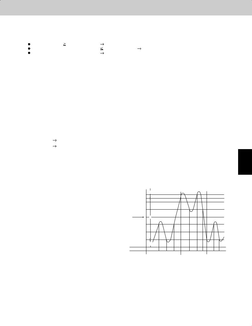
Remote Control Functions
1. Main Operating Functions
1-2. Automatic Control for Heating and Cooling
Automatic Heating/Cooling Control
(1) When operation starts, heating or cooling is selected according to the set temperature and the room temperature.
Room temperature Set temperature + 2 |
Cooling |
Set temperature – 2 < Room temperature |
Set temperature + 2 Monitoring mode (*1) |
Room temperature < Set temperature – 2 |
Heating |
*1: If the difference between the room temperature and set temperature is small when operation starts, the cooling thermostat remains in standby status (OFF) until the temperature difference increases. When the temperature difference increases, either cooling operation or heating operation is selected. This standby status is known as “monitoring mode.”
(2)After operation starts in the selected operating mode, the set temperature is automatically shifted by + 4°F (cooling operation) or – 4°F (heating operation).
Example: Temperature set on the remote controller is 68°F.
|
Selected operating mode |
Shifted set temp. |
Remote controller display |
|
|
|
|
1 |
Cooling |
72°F |
68°F |
|
|
|
|
2 |
Heating |
64°F |
68°F |
|
|
|
|
(3) Operating mode changes (heating  cooling, cooling
  heating) which occur during operation as a result of temperature changes are handled as shown below.
 Heating
 cooling: Room temperature
 Shifted set temperature (set temperature + 4°F + 1°F
  Cooling
 heating: Room temperature
 Shifted set temperature (set temperature – 4°F – 2°F
Example: Temperature set on the remote controller is 68°F.
|
Operating mode change |
Shifted set temp. |
|
|
|
|
|
1 |
Heating |
Cooling |
68 + 4 + 1 = 73°F or higher (*2) |
|
|
|
|
2 |
Cooling |
Heating |
68 – 4 – 2 = 62°F or lower |
|
|
|
|
*2: During heating operation when the body sensor is used, a temperature shift is applied to the intake temperature detected by the sensor, in consideration for the difference in temperature at the top and bottom of the room. (Refer to the “Room Temperature Control” item.) If this intake shift temperature is 7°F, then the heating  cooling change occurs when the temperature detected by the body sensor is 80°F or higher.
(4)Cooling (heating) operation does not change if the room temperature changes from area C  A (or A
  C) within 10 minutes after the compressor turns OFF. (Monitoring mode is excepted.)
1
2
|
+6 deg |
A |
|
|
|
3 |
|
|
|
|
|
|
|
Selected operating mode |
+5 deg |
|
|
|
|
|
Shifted set temp |
+4 deg |
|
|
|
|
|
|
+2 deg |
|
|
|
|
|
Remote controller display |
|
B |
|
|
|
4 |
|
|
|
|
|
||
|
–2 deg |
|
|
|
|
|
Shifted set temp |
–4 deg |
|
|
|
|
|
Selected operating mode |
–6 deg |
|
|
|
|
5 |
|
|
C |
|
|
|
|
Thermostat |
ON |
OFF ON |
|
|
||
OFF ON |
OFF ON OFF ON OFF ON |
|||||
|
|
|
Heating |
|
Cooling |
Heating |
|
|
|
|
|
|
6 |
|
|
|
|
|
|
7 |
2 - 3 |
|
|
|
|
|
|
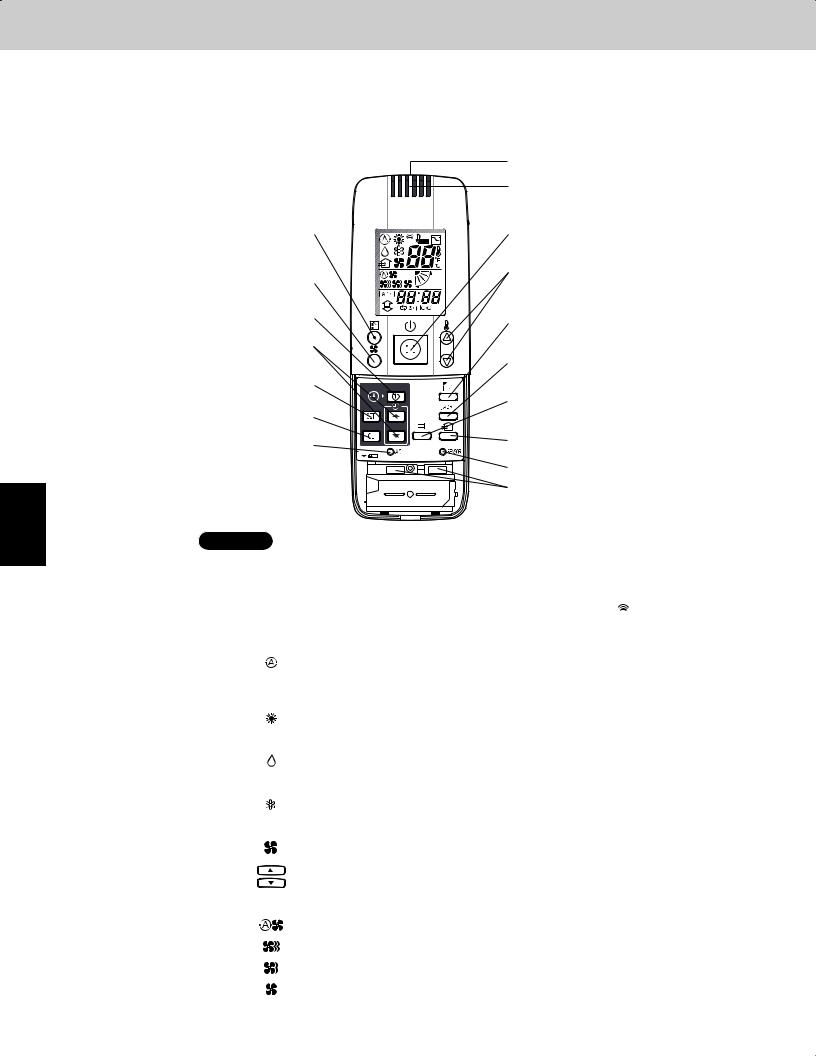
1
2
3
4
5
6
7
Remote Control Functions
2. Wireless Remote Controller
Optional Controller (Remote Controller)
Wireless Remote Controller / CZ-RWSU1U (for X Type) / CZ-RWST1U (for A, T Type) / CZ-RWSC1U (for U, D Type) / CZ-RWSK1U (for K Type) / CZ-RWSY1U
2-1. How to Use the Wireless Remote Controller |
B: Transmitter |
|
O: Remote control sensor |
C: MODE button |
A: ON/OFF operation button |
|
|
E: FAN SPEED selector button |
D: Temperature setting buttons |
|
|
J: TIMER SET button |
I: FLAP button |
|
|
K: Time setting buttons |
|
|
G: ADDRESS button |
L: SET button |
|
M: CL button |
F: FILTER button |
|
|
P: ACL button |
N: VENTILATION button |
|
|
(ALL CLEAR) |
H: A/C SENSOR button |
|
|
|
Q: Slide switch |
NOTE The illustration above pictures the wireless remote control unit after the cover has been lowered and removed.
A: ON/OFF operation button |
This button is for turning the air conditioner on and off. |
|
|||||||
|
|
|
|
|
|
|
|
|
|
B: Transmitter |
When you press the buttons on the wireless remote control unit, the mark appears in the |
||||||||
|
display to transmit the setting changes to the receiver in the air conditioner. |
|
|||||||
|
|
|
|
|
|
|
|
|
|
C: MODE button |
Use this button to select one of the following five operating modes. |
|
|||||||
(AUTO) |
|
|
|
|
|
|
|
: Used to automatically set cooling or heating operation. Only for single heat pump |
|
|
|
|
|
|
|||||
|
|
|
|
|
|
|
|
type |
|
|
|
|
|
|
|
|
|
(Temperature range: 62 ~ 80°F) |
|
(HEAT) |
|
|
|
|
|
|
|
: Used for normal heating operation. Only for heat pump type |
|
|
|
|
|
|
|
||||
|
|
|
|
|
|
|
|
(Temperature range: 60 ~ 78°F) |
|
(DRY) |
|
|
|
|
|
|
|
: Used for dehumidifying without changing the room temperature. |
|
|
|
|
|
|
|
|
|
||
|
|
|
|
|
|
|
|
(Temperature range: 64 ~ 86°F) |
|
(COOL) |
|
|
|
|
|
|
|
: Used for normal cooling operation. |
|
|
|
|
|
|
|
|
|
(Temperature range: 64 ~ 86°F) |
|
(FAN) |
|
|
|
|
|
|
|
: Used to run the fan only, without heating or cooling operation. |
|
|
|
|
|
|
|
|
|
|
|
D: Temperature setting buttons |
|
|
|
|
|
|
|
: Press this button to increase the temperature setting. |
|
|
|
|
|
|
|
|
|||
|
|
|
|
|
|
|
|
: Press this button to decrease the temperature setting. |
|
|
|
|
|
|
|
|
|
|
|
|
|
|
|
|
|
|
|
|
|
E: FAN SPEED selector button |
|
|
|
|
|
|
|
|
|
(AUTO) |
|
|
|
|
|
|
|
: The air conditioner automatically decides the fan speeds. |
|
(HI) |
|
|
|
|
|
|
|
: High fan speed |
|
(MED) |
|
|
|
|
|
|
|
: Medium fan speed |
|
(LO) |
|
|
|
|
|
|
|
: Low fan speed |
|
|
|
|
|
|
|
|
|
|
|
|
2 - 4 |
Continued |
|||||||
|
|
||||||||
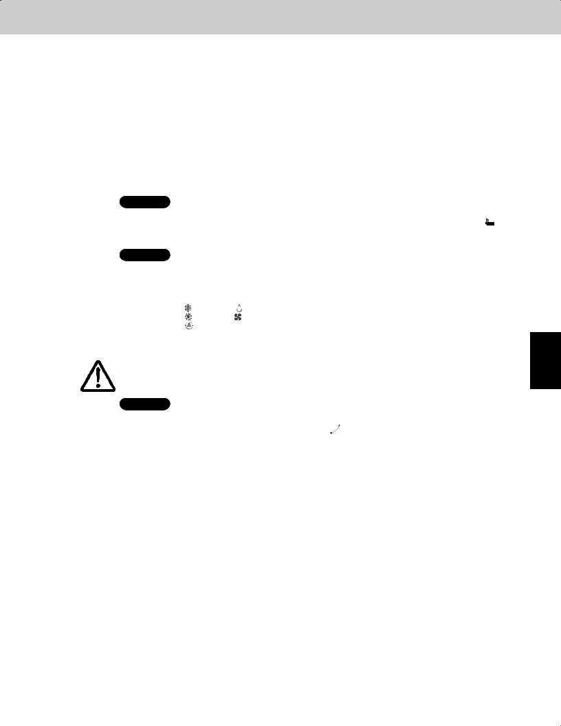
Remote Control Functions
2. Wireless Remote Controller
F: FILTER button |
If a separately installed signal receiver is being employed, this button is used to turn off its |
||||||
|
|
|
filter lamp. When the filter lamp has lighted, first clean the filter, and then press the FILTER |
||||
|
|
|
button to turn off the filter lamp. When a wired remote control unit and wireless remote |
||||
|
|
|
control unit are both used, the filter sign on the wired remote control unit will appear. When |
||||
|
|
|
this happens, first clean the filter, and then press the FILTER button on one of the remote |
||||
|
|
|
control units to turn off the filter sign. |
|
|
|
|
G: ADDRESS button |
When a multiple number of indoor units that can be operated by the wireless remote |
||||||
|
|
|
control unit have been installed in the same room with a multi-unit or single-unit installation, |
||||
|
|
|
this button enables addresses to be set in order to prevent the sending of signals to the |
||||
|
|
|
wrong indoor unit. Each of up to six indoor units can be controlled separately using its own |
||||
|
|
|
wireless remote control unit by matching the number of the address switch on the operation |
||||
|
|
|
area of the indoor unit and the number used for the address of its remote control unit. (The |
||||
|
|
|
indoor units cannot be controlled separately when they are used in a flexible combination |
||||
|
|
|
format, simultaneous operation of multi units format or any other such format since they will |
||||
|
|
|
all operate at the same time.) |
|
|
|
|
|
NOTE |
When the batteries are replaced, the address setting returns to "ALL", so you must make |
|||||
|
|
|
the setting again. |
|
|
|
|
H: A/C SENSOR button |
When you press this button (use a narrow-tipped object such as a ballpoint pen), the |
|
|
||||
|
|||||||
|
|
|
indication will disappear on the display. The room temperature is detected by the sensor |
|
|||
|
|
|
which is built into the indoor unit and the air conditioner is controlled accordingly. |
||||
|
NOTE |
If the remote control is located near a heat source, such as a space heater or in direct |
|||||
|
|
|
sunlight, press the A/C SENSOR button to switch to the sensor on the indoor unit. |
||||
I: FLAP button |
1. Use this button to set the airflow direction to a specific angle. |
||||||
|
|
|
The airflow direction is displayed on the remote control unit. |
||||
|
|
|
Operation mode |
Number of airfl ow direction settings |
|||
|
|
|
(COOL) or |
(DRY) |
3 |
|
|
|
|
|
(HEAT) or |
(FAN) |
5 |
|
|
|
|
|
(AUTO) |
|
|
|
|
|
|
|
Cooling mode: |
3 |
|
|
|
|
|
|
Heating mode: |
5 |
|
|
|
|
|
|
|||||
|
CAUTION |
|
In the Cool mode and Dry mode, if the flaps are set in a downward |
||||
|
|
|
position, condensation may form and drip around the vent. |
||||
|
|
|
Do not move the flap with your hands. |
|
|
|
|
|
NOTE |
This function is available only for models X, XM, A, T and K. |
|||||
|
(SWEEP) |
|
|
|
|||
|
2. Use this button to make the airflow direction sweep up and down automatically. |
||||||
|
|
|
Press this button several times until the |
symbol appears on the display. |
|||
|
|
|
To stop the swing operation |
|
|
|
|
|
|
|
Press the FLAP button again during the flap swing operation to stop the flap at the desired |
||||
|
|
|
position. Then, the airflow can be set from the top position by pressing the FLAP button |
||||
|
|
|
again. |
|
|
|
|
|
|
|
|
|
|
|
|
1
2
3
4
5
6
7
2 - 5

1
2
3
4
5
6
7
Remote Control Functions
2. Wireless Remote Controller
Indicator when swing operation is stopped
Fan and heating |
Cooling and drying |
||||
|
|
|
|
|
|
|
|
|
|
|
|
|
|
|
|
|
|
|
|
|
|
|
|
|
|
|
|
|
|
|
During cooling and drying, the flap does not stop at the downward position. |
|
|
Even if the flap is stopped at the downward position during the swing operation, it does not |
|
|
stop until it moves to the third position from the top. |
|
NOTE |
This function is available only for models X, XM, A, T and K. |
|
|
|
|
J: TIMER SET button |
Use this button while the unit is operating to switch between timer settings. |
|
(OFF Timer) |
|
: The air conditioner stops after a preset time elapses. |
|
|
|
(OFF Cycle Timer) |
|
: The air conditioner always stops after a preset time elapses. |
(ON Timer) |
|
: The air conditioner starts after a preset time elapses. |
|
|
|
K: Time setting buttons |
: Press this button to increase the time. |
|
|
: Press this button to decrease the time. |
|
|
|
|
L: SET button |
Use this button to set the timer. |
|
|
|
|
M: CL button |
Use this button to clear the timer setting. |
|
|
|
|
N: VENTILATION button |
This is used when a ventilation fan (available commercially) is connected. Pressing the |
|
|
VENTILATION button turns the fan on and off. The ventilation fan also turns on and off when |
|
|
the air conditioner unit is turned on and off. (The display of the remote control unit shows |
|
|
" " while the ventilation fan is running.) |
|
*If the VENTILATION button is held down for 4 or more seconds when the batteries have been replaced, " " appears on the display, and the ventilation fan can be used.
O:Remote control sensor This detects the temperature around the remote control unit when the remote control unit
position has been selected using the sensor button.
P: ACL button (ALL CLEAR) |
Puts the wireless remote control unit into pre-operation status. This is used after the batter- |
|
|
ies have been replaced or when the slide switch setting has been changed. |
|
|
|
|
Q: Slide switch |
This switch is for setting the operation mode of the indoor unit and setting the flaps. |
|
|
|
|
|
NOTE |
The wireless remote control unit sends the temperature signal to the air |
|
|
conditioner regularly at five-minute intervals. If the signal from the wireless |
|
|
remote control unit stops for more than ten minutes due to the loss of the |
|
|
wireless remote control unit or other trouble, the air conditioner will switch to |
the temperature sensor which is built into the indoor unit and control the room temperature. In these cases, the temperature around the wireless remote control unit may differ from the temperature detected at the air conditioner's position.
 When low fan speed is selected and the air conditioner is in cooling operation at a low outdoor temperature of less than 50°F, the air conditioner may automatically switch to medium fan speed to prevent freezing.
2 - 6
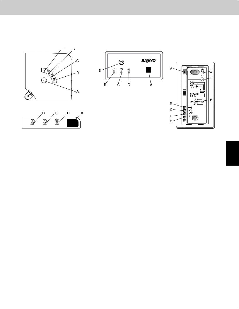
Remote Control Functions
2. Wireless Remote Controller
2-2. Receiver
The signal receivers with the exception of the separately installed signal receiver are mounted on the indoor units.
X, XM types |
A, T types |
Separately installed signal receiver
(U, D types)
K type
1
A: Receiver |
This section picks up infrared signals from the wireless remote control unit (transmitter). |
|
|
|
|
Indication lamps |
One of these lamps will blink when trouble has occurred. When an indicator lamp starts to |
|
|
|
blink, refer to “Trouble Diagnosis” on page 2-14. |
|
|
|
|
B: Operation lamp |
This lamp lights when the appliance is turned on. |
|
|
|
|
C: Timer lamp |
This lamp lights when the system is being controlled by the timer. |
|
|
|
|
D: Standby lamp |
• This lamp lights at the following times during heating operations: |
|
|
When operation has started, when the thermostat has been activated, during defrosting |
|
|
operation. |
|
|
• The lamp blinks when trouble has occurred. |
|
|
|
E: Emergency operation |
This is used when operation cannot be performed due to trouble with or loss of the wireless |
|
|
button |
remote control unit. |
|
|
|
F: ADDRESS switch |
This switch is used in order to prevent the sending of signals to the wrong indoor unit when |
|
|
|
a multiple number of indoor units that can be operated by the wireless remote control units |
|
|
have been installed in the same room. |
|
|
|
G: SWING button |
When this button is pressed, the airflow sweeps up and down automatically. |
|
|
|
|
H: FILTER lamp |
This lamp lights to indicate that it is time to clean the filter. |
|
|
|
|
•If two beeps are heard, the operation lamp among the indication lamps has lighted and the timer lamp and standby lamp blink alternately. In cases where heat pump models are used, this indicates a Cooling/Heating mode mismatch and, as such, operation in the desired mode cannot be performed.
(The same beeps will be heard and the same operation lamps will light when auto cooling/heating has been selected on a model which does not have the auto cooling/heating function.)
•When local operation has been set to disable because the centralized control mode is established, for instance, pressing the ON/OFF operation button, MODE button or temperature setting buttons results in the sounding of five beeps, and the attempted change in the operation will not be accepted.
2
3
4
5
6
7
2 - 7
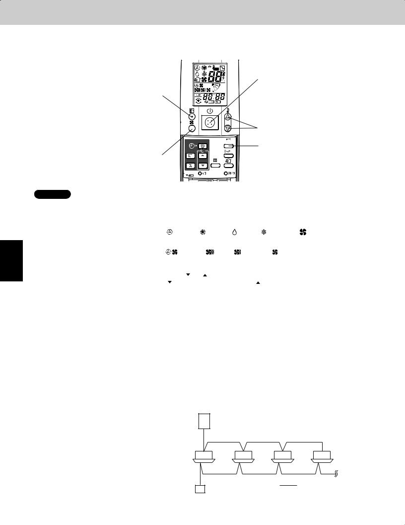
1
2
3
4
5
6
7
Remote Control Functions
2. Wireless Remote Controller
2-3. Operation
STEP 1, 6
STEP 2
STEP 4
STEP 5
STEP 3
NOTE • To warm up the system, the power mains must be turned on at least five (5) hours before operation.
STEP 1 To start the air conditioner:
STEP 2 Setting the mode:
STEP 3 Setting the fan speed:
STEP 4 Setting the temperature:
STEP 5 Setting the airflow direction:
STEP 6 To stop the air conditioner:
Automatic heating and cooling
Simultaneous operation of |
Group control is suitable for air conditioning of a large room using multiple air conditioning |
|
multiple units (Group |
units. |
|
control) |
• |
One remote control unit can control up to eight indoor units. |
|
||
|
• |
All indoor units have the same settings except for the airflow direction. |
|
• The temperature sensors at the indoor unit side are used. |
|

Remote Control Functions
2. Wireless Remote Controller
2-4. Using the Wireless Remote Control Unit
Slide switch This is used to set the operation mode of the indoor units and to set the flaps.
•Depending on the indoor unit used, the operation display and airflow direction display settings will differ as shown below.
•Use a pointed implement to change the switch position.
•When the switch position has been changed, press the ACL button.
* For details on the flap functions, refer to the operating instructions of the indoor unit used.
With the battery cover removed
How to install batteries
How to use the wireless remote control unit
Model which supports |
Swing-only model |
No-flap model |
|
different flap settings |
|||
|
|
Slide switch position
Flap display on wireless remote control unit
Heat pump (with auto |
Heat pump (without |
|
cooling/heating |
auto cooling/heating |
Cooling only |
function) |
function) |
|
Operation mode display on wireless remote control unit
Slide switch position
•Before use, check that the slide switch has been set to the position shown in the figure above. For details on how to set the slide switch, consult your dealer.
1.Slide the cover in the direction indicated by the arrow and remove it.
2.Install two AAA alkaline batteries. Make sure the batteries point in the direction marked in the battery compartment.
3.Use a pointed implement to press the ACL button.
• The batteries last about a year, depending on how much |
|
|
you use the wireless remote control unit. Replace the |
ACL |
|
batteries when the wireless remote control unit's display |
button |
|
fails to light, or when the remote control cannot be used |
Cover |
|
to change the air conditioner's settings. |
||
|
•When the batteries are to be replaced, make sure that both batteries are new and that the same kind of battery is used.
•Remove the batteries if the wireless remote control unit is not going to be used for a prolonged period.
•Dispose of the used batteries at the designated location.
•Point the wireless remote control unit's transmitter at the signal receiver. If the signal is received properly, a beep is heard. (Two beeps are heard only when operation starts up.)
•Signals can be received over a distance of approximately 26 ft. This distance is approximate: it may be slightly more or less depending on how much charge remains in the batteries and on other factors.
•Ensure that the signals will not be blocked by any objects positioned between the transmitter and signal receiver.
•Avoid placing the wireless remote control unit where it will be exposed to direct sunlight or in the direct path of the air blown out from the air conditioner, near a heating appliance, etc.
•Do not drop, throw or wash the wireless remote control unit.
•Signal reception may not be accepted in rooms with fluorescent lights that use the electronic instantaneous lighting system (rapid start system) or inverter system.
For further details, contact your dealer.
2 - 9
1
2
3
4
5
6
7

Remote Control Functions
2. Wireless Remote Controller
When mounting the wireless remote control unit on a wall for use
•Before mounting the wireless remote control unit on the wall, place the unit at the mounting position, press the ON/OFF operation button and check that the signals are received properly.
•To remove the wireless remote control unit, disengage it by pulling it toward you.
Secure the installation fitting of the wireless remote control unit using the screws.
1
Press.
2
Installation fitting of wireless remote control unit
Place here.
Procedure for installing the wireless remote control unit
Operating tips
1
2 |
2-5. Address Settings |
|
3
How to check the
addresses
4
5 |
How to set the |
matching address |
6
7 |
NOTE |
|
|
|
|
•Do not operate the wireless remote control unit too far away from the signal receiver.
Doing so may cause operational errors.
Make absolutely sure that the wireless remote control unit and signal receiver are both in the same room.
•When operating the wireless remote control unit, point it directly at the signal receiver.
A beep is heard when a signal is received properly.
•Avoid places where the wireless remote control unit will be obscured by curtains, etc.
Remove it before operation.
When a multiple number of indoor units that can be operated by the wireless remote control unit have been installed in the same room with a multi-unit or single-unit installation, this button enables addresses to be set in order to prevent the sending of signals to the wrong indoor unit. Each of up to six indoor units can be controlled separately using its own wireless remote control unit by matching the number of the address switch on the operation area of the indoor unit and the number used for the address of its wireless remote control unit. (The indoor units cannot be controlled separately when they are used in a flexible combination format, simultaneous operation of multi units format or any other such format since they will all operate at the same time.)
The signal receiver has an address switch for signal reception, and the wireless remote control unit has an address switch for signal transmission.
When the ADDRESS button on the wireless remote control unit is pressed, the current address appears on the wireless remote control unit's display. The buzzer sounds if the address displayed matches the signal receiver's address. (The buzzer always sounds if “ALL” appears as the address display.)
If “ALL” appears as the address display, operations can be performed irrespective of the signal receiver's address. Point the wireless remote control unit at the signal receiver of the unit to be operated, and send the signal.
Wireless remote control unit s address setting
1.When the ADDRESS button is held down for 4 or more seconds, “  ” lights on the wireless remote control unit's display, and the current address blinks.
2.Each time the ADDRESS button is now pressed, the address changes by one setting in the following sequence: ALL  1
1  2
2  3
3  6
6  ALL.
ALL.
Select the setting which matches the setting of the address switch in the operation area of the indoor unit to be operated.
3. When the SET button is now pressed, the address stops blinking and lights instead, and it remains on the display for 5 seconds.
The buzzer sounds if the setting matches the setting of the address switch in the operation area of the indoor unit.
When the batteries are replaced, the address setting returns to “ALL ”.
2 - 10
 Loading...