


Hardware Manual

Thank you for purchasing the Minolta Dimâge Scan Multi II. The Dimâge Scan Multi II is a multiple format film scanner capable of scanning medium format, 35mm, 16mm, and sleeved APS film. With the optional APS adapter, advanced photo system film in the cassette can also be scanned.
Your new scanner has extraordinary features, including:
•Medium-format film scanning capability. The included medium-format film holder uses antinewton glass and includes masks for 6x4.5, 6x6, 6x7, 6x9.
•12-bit AD converter, so fine detail is captured with a dynamic range.
This manual has been designed to help you understand the operation of your scanner. To realize all the benefits of your scanner, please read this manual and the accompanying software manual thoroughly.
The instructions in this manual assume you have a working knowledge of the operating system for your computer (Mac OS, Windows 95, or Windows NT) and its conventions. Familiarity with the mouse and standard operating system menus and commands is necessary before operating the Dimâge Scan Multi II software.
This manual does not instruct in the:
•basic use of personal computers.
•use of Window 95, Windows NT, or Mac OS.
•use of Adobe Photoshop, Paint Shop Pro, or Corel Draw.
Microsoft, Windows®, Windows 95®, and Windows NT® are registered trademarks of the Microsoft Corporation.
Macintosh™, Apple®, and Power Macintosh® are registered trademarks of Apple Computer, Inc.
Other corporate and product names are the trademarks and registered trademarks of their respective companies.
•Changes or modifications not approved by the party responsible for compliance could void the user’s authority to operate the equipment.
•This manual may not be copied in part or whole without prior written permission from Minolta Co., Ltd. ©1998 Minolta Co., Ltd.
•Every necessary caution has been taken to ensure the accuracy of this instruction manual. Please contact us if you have any questions, find any errors, or notice missing information.
•Minolta is not responsible for loss, damage, or other results occurring during the operation of this product.
This mark certifies that this product meets the requirements of the EU (European Union) concerning interference causing equipment regulations. CE stands for Conformité Européenne.
This device complies with Part 15 of the FCC Rules. Operation is subject to the following conditions: (1) This device may not cause harmful interference, and (2) this device must accept any interference received, including interference that may cause undesired operation.
Do not remove the ferrite cores from the SCSI cable.
This Class B digital apparatus complies with Canadian ICES-0003.
Cet appareil numérique de la classe B est conforme à la norm NMB-003 du Canada.
Tested by the Minolta Corporation
101 Williams Drive
Ramsey, New Jersey 07446
USA
FOR PROPER AND SAFE USE
Please read and understand each caution before using this product.
CAUTION
To avoid fire or electric shock:
•Only use the voltage specified for this unit.
•Do not expose this unit to liquids.
•Do not insert metal objects into this unit.
•Do not touch the cord or plug if your hands are wet.
•Unplug this unit when it is not in use.
Improper use of the power cord may result in fire or electric shock.
•Insert the plug securely into an electrical outlet.
•Do not pull on the cord. Grasp the plug when removing the power cord from an
outlet.
•Do not scratch, twist, modify, heat, or place a heavy object on the power cord.
•Do not connect the ground to a gas pipe, telephone ground, or a water pipe. Improper grounding can result in electric shock.
This product must have sufficient ventilation while in use. Blocked ventilation ducts may cause the unit to overheat, increasing the risk of fire.
• Do not use or store this product in dusty or very humid areas.
If there is smoke, a strange smell, or any other unusual conditions, shut down and unplug the unit, then contact a Minolta Service Facility.
Do not attempt to disassemble this product. It contains high-voltage circuits. Take the product to a Minolta Service facility for repairs.
Unexpected damage may occur if this unit is left unattended near young children.
1

TABLE OF CONTENTS
FOR PROPER AND SAFE USE .................................................................................. |
1 |
BEFORE YOU BEGIN |
|
Package Contents......................................................................................................... |
4 |
System Requirements .................................................................................................. |
5 |
NAMES OF PARTS |
|
Front.............................................................................................................................. |
6 |
Back .............................................................................................................................. |
7 |
Important: Locking Pin Information............................................................................... |
7 |
SETTING THE SCSI ID ................................................................................................ |
8 |
CONNECTING TO THE COMPUTER |
|
If the Scanner is the Only or Last Device in the Chain ................................................ |
9 |
If the Scanner is Inside the Chain ................................................................................ |
11 |
GETTING STARTED |
|
Film Emulsion ............................................................................................................... |
14 |
Handling Care............................................................................................................... |
14 |
LOADING 35MM FILM HOLDERS |
|
Slide Mount Holder SH-M1........................................................................................... |
15 |
35mm Film Holder FH-M1 ............................................................................................ |
16 |
LOADING THE MEDIUM FORMAT FILM HOLDER MH-M1 |
|
Using the Medium Format Film Holder MH-M1............................................................ |
18 |
Medium Format and TEM Film ..................................................................................... |
18 |
16mm and APS Sleeve Film......................................................................................... |
20 |
Rotating the Frame ....................................................................................................... |
22 |
INSERTING THE HOLDER INTO THE SCANNER...................................................... |
23 |
Ejecting ......................................................................................................................... |
23 |
APS ADAPTER AD-100 (SOLD SEPARATELY)........................................................... |
24 |
APS Adapter – Names of Parts.................................................................................... |
24 |
Loading the Cassette.................................................................................................... |
25 |
Inserting the Adapter .................................................................................................... |
26 |
Ejecting the Adapter ..................................................................................................... |
27 |
CHANGING THE FLUORESCENT LAMP.................................................................... |
28 |
IMPORTANT: BEFORE TRANSPORTING THE SCANNER ........................................ |
30 |
TROUBLESHOOTING.................................................................................................. |
31 |
2

INDICATOR LAMP........................................................................................................ |
33 |
TECHNICAL DETAILS.................................................................................................. |
34 |
CUSTOMER SERVICE................................................................................................. |
35 |
Minolta .......................................................................................................................... |
36 |
3

BEFORE YOU BEGIN
PACKAGE CONTENTS
CHECK THIS PACKING LIST BEFORE YOU BEGIN. IF SOME PARTS ARE MISSING, CONTACT YOUR DEALER OR A MINOLTA SERVICE FACILITY.
•Minolta Dimâge Scan Multi II scanner
•35mm Film Holder FH-M1
•35mm Slide Mount Holder SH-M1
•Medium Format Film Holder MH-M1
•Film Masks:
6 x 4.5 Medium Format Film Mask
6 x 6 Medium Format Film Mask
6 x 7 Medium Format Film Mask
6 x 8 Medium Format Film Mask
6 x 9 Medium Format Film Mask
APS Sleeve Film Mask
16mm Film Mask
•Power Cord PW-M2
•SCSI Cable SC-11
•Dimâge Scan Multi II CD-ROM v1.0
•Instruction Manuals (1 software, 1 hardware)
•Warranty and Software Registration card
4

SYSTEM REQUIREMENTS
MACINTOSH
CPU: Power PC, Power Macintosh G3, Blue & White Power Macintosh G3 and Power Macintosh G4 (Except for 68 K Macintosh and Mac OS compatible unit). Power Macintosh G4 is recommended when loading with 16 bit and using the Digital ROC/GEM functions.
Operation System: |
Mac OS 7.5.3 to 9.0.4 |
Memory: |
A minimum of 32 MB (megabytes) application RAM in addition to the requirements for the |
|
Mac OS. |
|
256 MB or more when loading with 16 bit and using the Digital ROC/GEM functions. |
Hard Disk Space: |
About 600 MB or more of available hard disk space. |
|
About 2 GB or more of available hard disk space when loading with 16 bit and using the |
|
Digital ROC/GEM functions. (About 3 GB or more is recommended.) |
Monitor: |
Minimum 13 (640 x 480) inch monitor capable of displaying at least 32,000 Colors. |
|
19 inch(1024 x 768) or larger is recommended. |
CD-ROM Drive: Necessary (when installing the software.)
Recommended SCSI Board:
With a Power Macintosh and Power Macintosh G3 The standard built-in SCSI board
Connecting to the extension board inserted into the PCI bus/NuBus is not available.)
With a Blue & White Power Macintosh G3*, Power Macintosh G4
Adaptec PowerDomain 2940UW/U2W, PowerDomain 2930U, SCSI Card 2906, and AVA-
|
2903B |
|
* Some models in the Blue & White Power Macintosh G3 series use the Ultra2 Wide SCSI |
|
board as the standard built-in SCSI board, however, connecting the Dimage Scan Multi II to |
|
the standard built-in SCSI board is not recommended. The connecting capacity may be |
|
limited and the full capabilities of the PC may not be usable due to the specifications of the |
|
standard built-in SCSI board. |
|
When using the model which has the standard built-in SCSI board, insert the |
|
recommended SCSI board as described above in the open slot without detaching the |
|
standard built-in SCSI board and then connect the Dimage Scan Multi II to the SCSI |
|
connctor on the inserted SCSI board. |
Other: |
Adobe PhotoShop Ver. 4.0.1, Ver. 5.0.2, Ver. 5.5 and Adobe Photoshop 5.0 LE have been |
|
fully tested for use with the plug-in software. |
MACINTOSH
CPU: |
IBM PC/AT compatible with an Intel Pentium processor 90 MHz or above. |
|
• Support cannot be provided for custom or home built machines. |
|
Pentium III Processor is recommended when loading with 16 bit or using the Digital |
|
ROC/GEM functions. |
Orerating System: |
Windows®95 (inc. OSR2), Windows®98 (inc. Second Edition), Windows®2000 |
|
Professional, Windows®NT 4.0 |
Memory: |
A minimum of 32 MB (megabytes) of RAM. |
|
A minimum of 512 MB when loading with 16 bit and using the Digital ROC/GEM functions. |
Hard Disk Space: |
About 600 MB or more of available hard disk space. |
|
About 2 GB or more of available hard disk space when loading with 16 bit and using the |
|
Digital ROC/GEM functions. (About 3 GB or more is recommended.) |
Monitor: |
Minimum VGA (640 x 480) monitor capable of displaying High Color (16 bit) is required. |
|
XGA (1024 x 768) or larger is recommended. |
CD-ROM Drive: Necessary (when installing the software.)
Recommended SCSI Board:
Adaptec AHA-1510B, AHA-1520B, AHA-1540CP, AHA-2910B, AHA-2910C, AHA-2920C, AHA-2940, AHA-2940U/W/AU/UW/U2W, SCSI Card 19160/29160/29160N, AVA2902E/2903B/2906
Other: |
Photoshop Ver. 3.0.5, Ver.4.0.1, Ver. 5.0.2, Ver. 5.5, Photoshop 5.0 LE, Paint Shop Pro Ver. |
|
6, Corel PHOTO-PAINT Ver. 9* have been fully tested for use with the TWAIN driver |
|
software. |
|
*Corel Scan is not recommended. |
5
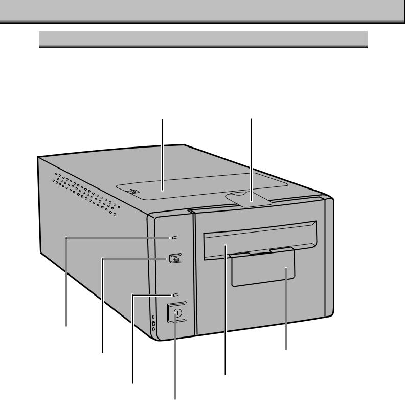
NAMES OF PARTS
FRONT
|
|
Connector cover |
Fluorescent lamp unit cover |
|
|
|
|
|
|
|
|
|
|
|
Indicator lamp
Eject button |
|
|
|
Accessory panel |
|
|
|
|
|
||
|
|
|
|
Film-slot door |
|
|
|
Power lamp |
|
||
|
|
|
|
|
|
|
|
|
|
|
|
|
|
|
Power switch |
||
|
|
|
|
|
|

BACK
|
|
|
|
|
|
|
|
|
|
|
|
|
|
|
|
|
|
|
|
|
|
|
|
|
|
|
|
|
|
|
|
|
|
|
|
|
|
|
|
|
|
|
|
|
|
|
|
|
|
|
|
|
|
|
|
|
|
|
|
|
|
|
|
|
|
|
|
|
AC socket |
||
|
|
|
|
|
|
|
|
|
|
|
|
|
|
|
|
Centronics |
|
|
|
|
|||
SCSI ID switch |
|
|
|
|
|
|
|||||
|
|
|
|
|
|
|
|
|
|
|
|
|
|
|
|
|
|
|
|
|
|
|
|
|
|
|
|
|
|
|
|||||
|
|
|
Terminator dip switch |
||||||||
|
|
|
|
D-sub-25 port |
|||||||
|
|
|
|
|
|
|
|
|
|
|
|
IMPORTANT: LOCKING PIN INFORMATION
UNLOCK THE OPTICS BEFORE
USING THE SCANNER FOR THE
FIRST TIME.
The optics inside the scanner have been parked and locked before shipment for their protection.
Before using the scanner for the first time, unlock the locking pin.
• Gently turn the scanner up-side down. Using a flat-head screwdriver, turn the locking pin counterclockwise until it pops up.
7
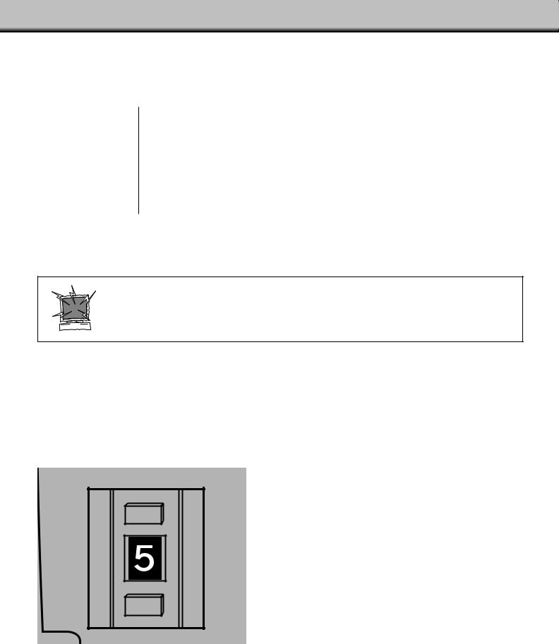
SETTING THE SCSI ID
The Dimâge Scan Multi II’s SCSI ID is factory preset to 5. If 5 is not being used by another operating SCSI device in the SCSI chain, it is not necessary to change the SCSI ID.
A SCSI ID is a unique address you assign to each SCSI device connected to your computer. The SCSI ID range of your computer is from 0 to 7, however some IDs are already occupied by your computer.
|
Occupied SCSI ID |
|
|
|
|
IBM PC/AT: |
7 |
(SCSI host adapter) |
|
|
|
Macintosh: |
0 |
(internal hard drive)* |
|
3 |
(internal CD-ROM drive)** |
7(system)
*IDE Macintosh systems do not use SCSI ID 0 for the hard drive.
**Macintosh systems with a dual bus have SCSI ID 3 available on the external bus.
TURN OFF THE COMPUTER AND ALL THE SCSI DEVICES
BEFORE CHANGING SCSI IDS, CONNECTING SCSI
CABLES, OR DISCONNECTING SCSI CABLES.
TO CHANGE THE SCSI ID:
1.Turn off the computer and all connected SCSI devices.
2.Determine which SCSI IDs are not being used.
3.Change the SCSI ID using the upper or lower SCSI buttons.
 Press the upper button to select a smaller SCSI number.
 The current SCSI ID number.
 Press the lower button to select a higher SCSI number.
8
CONNECTING TO THE COMPUTER
IF THE SCANNER IS THE ONLY OR LAST DEVICE IN THE CHAIN…
TURN OFF THE COMPUTER AND ALL THE SCSI DEVICES
BEFORE CHANGING SCSI IDS, CONNECTING SCSI
CABLES, OR DISCONNECTING SCSI CABLES.
One D-sub-25 to Centronics 50 cable is included with your scanner. Please see your dealer if you require a different cable.
1.Connect one end of the SCSI cable to either SCSI port on the back of the scanner.
• Either SCSI port can be used, there is no dedicated in or out port.
2. Connect the other end of the SCSI cable to the SCSI port on the computer or on the last SCSI device in the chain.
3.Flip the dip switch marked 1 up to turn the terminator on.
• Dip switches 2 through 4 are inactive. Their position will not affect the scanner operation.
9 |
Continued on following page. |

CONNECTING TO THE COMPUTER
4.Plug the power cord into the scanner’s AC socket.
5.Plug the other end of the power cord into a grounded outlet.
10
 Loading...