


 Loading...
Operation & Safety
Manual
Keep this manual with machine at all times.
Models
G5-19A
&
G6-23A
31200192
Revised
August 29, 2007
An Oshkosh Truck Corporation Company

CALIFORNIA PROPOSITION 65
BATTERY WARNING
Battery posts, terminals and related accessories contain lead and lead compounds, chemical known to the State of California
to cause cancer and reproductive harm.
WASH HANDS
AFTER HANDLING!
CALIFORNIA PROPOSITION 65
EXHAUST WARNING
Diesel Engine exhaust and some of its constituents are known to the State of California to cause cancer, birth defects and other reproductive harm.

Revision Log
REVISION LOG
March 24, 2006 - A - Original Issue of Manual
August 29, 2007 - B - Revised pages 2-3, 2-4, 2-5, 3-2, 3-3, 3-7, 3-8, 3-9, 3-12, 3-14, 3-19, 4-1, 4-7, 4-8, 5-11, 5-14 thru 5-17, 5-22, 7-14, 7-15, 7-16, 9-2, 9-3 and 9-4.
31200192 |
a |

Read This First
This manual is a very important tool! Keep it with the machine at all times.
The purpose of this manual is to provide owners, users, operators, lessors, and lessees with the precautions and operating procedures essential for the safe and proper machine operation for its intended purpose.
Due to continuous product improvements, JLG Industries, Inc. reserves the right to make specification changes without prior notification. Contact JLG Industries, Inc. for updated information.
Operator Qualifications
The operator of the machine must not operate the machine until this manual has been read, training is accomplished and operation of the machine has been completed under the supervision of an experienced and qualified operator. Operation within the U.S.A. requires training per OSHA 1910.178.
Operators of this equipment must possess a valid, applicable driver’s license, be in good physical and mental condition, have normal reflexes and reaction time, good vision and depth perception and normal hearing. Operator must not be using medication which could impair abilities nor be under the influence of alcohol or any other intoxicant during the work shift.
In addition, the operator must read, understand and comply with instructions contained in the following material furnished with the telehandler:
•This Operation & Safety Manual
•Telehandler Safety Manual
•All instructional decals and plates
•Any optional equipment instructions furnished
The operator must also read, understand and comply with all applicable Employer, Industry and Governmental rules, standards and regulations.
Modifications
Any modification to this machine must be approved by JLG.
b |
31200192 |

Read This First
This product must comply with all safety related bulletins. Contact JLG Industries, Inc. or the local authorized JLG representative for information regarding safetyrelated bulletins which may have been issued for this product.
JLG Industries, Inc. sends safety related bulletins to the owner of record of this machine. Contact JLG Industries, Inc. to ensure that the current owner records are updated and accurate.
JLG Industries, Inc. must be notified immediately in all instances where JLG products have been involved in an accident involving bodily injury or death of personnel or when damage has occurred to personal property or the JLG product.
FOR:
•Accident Reporting and Product Safety Publications
•Current Owner Updates
•Questions Regarding Product Applications and Safety
•Standards and Regulations Compliance Information
•Questions Regarding Product Modifications
CONTACT:
Product Safety and Reliability Department
JLG Industries, Inc.
1 JLG Drive
McConnellsburg, PA 17233
USA
or Your Local JLG Office (Addresses on back cover)
In USA:
Toll Free: 877-JLG-SAFE (877-554-7233)
Outside USA:
Phone: 717-485-5161 or 717-485-6591
E-mail: ProductSafety@JLG.com
Other Publications Available |
|
Service Manual ............................................................. |
31200193 |
Illustrated Parts Manual................................................. |
31200194 |
31200192 |
c |

Read This First
This Page Intentionally Left Blank
d |
31200192 |

|
Table of Contents |
|
|
TABLE OF CONTENTS |
|
Revision Log |
|
|
Read This First |
|
|
|
Operator Qualifications ...................................................... |
b |
|
Modifications ...................................................................... |
b |
|
Other Publications Available .............................................. |
c |
Table of Contents |
|
|
Section 1 - General Safety Practices |
|
|
1.1 |
Hazard Classification System .............................................. |
1-1 |
|
Safety Alert System and Safety Signal Words................ |
1-1 |
1.2 |
General Precautions ............................................................ |
1-1 |
1.3 |
Operation Safety.................................................................. |
1-2 |
|
Electrical Hazards ........................................................... |
1-2 |
|
Tip Over Hazard.............................................................. |
1-3 |
|
Travel Hazard ................................................................. |
1-6 |
|
Load Falling Hazard........................................................ |
1-7 |
|
Lifting Personnel ............................................................. |
1-8 |
|
Driving Hazards on Slopes ............................................. |
1-9 |
|
Pinch Points and Crush Hazards .................................. |
1-10 |
|
Fall Hazard.................................................................... |
1-12 |
|
Chemical Hazards......................................................... |
1-13 |
Section 2 - Pre-Operation and Inspection |
|
|
2.1 |
Pre-Operation Check and Inspection................................... |
2-1 |
2.2 |
Safety Decals....................................................................... |
2-3 |
2.3 |
Walk-Around Inspection....................................................... |
2-6 |
2.4 |
Warm-Up and Operational Checks...................................... |
2-8 |
|
Warm-Up Check ............................................................. |
2-8 |
|
Operational Check .......................................................... |
2-8 |
2.5 |
Operator Cab ....................................................................... |
2-9 |
2.6 |
Windows ............................................................................ |
2-10 |
|
Cab Door Window (if equipped).................................... |
2-10 |
|
Rear Window ................................................................ |
2-10 |
Section 3 - Controls and Indicators |
|
|
3.1 |
General ................................................................................ |
3-1 |
3.2 |
Controls ............................................................................... |
3-2 |
|
Instrument Panel............................................................. |
3-4 |
|
Ignition ............................................................................ |
3-6 |
|
Park Brake ...................................................................... |
3-7 |
|
Parking Procedure .......................................................... |
3-7 |
|
Transmission Control Lever ............................................ |
3-8 |
31200192 |
i |

Table of Contents
|
Gear Selection Switch .................................................... |
3-9 |
|
Accessory Control Lever (if equipped) ......................... |
3-10 |
|
Steering Column Adjuster............................................. |
3-11 |
|
Joystick......................................................................... |
3-12 |
|
Control and Indicator Console ...................................... |
3-16 |
|
Heater and Air Conditioner Controls (if equipped)........ |
3-17 |
3.3 |
Steer Modes ...................................................................... |
3-18 |
3.4 |
Operator Seat.................................................................... |
3-19 |
|
Adjustments.................................................................. |
3-19 |
|
Seat Belt ....................................................................... |
3-20 |
3.5 |
Boom Angle and Extension Indicators .............................. |
3-21 |
Section 4 - Operation
4.1 Engine ................................................................................. |
4-1 |
Starting the Engine ......................................................... |
4-1 |
Battery Boosted Starting................................................. |
4-2 |
Normal Engine Operation ............................................... |
4-3 |
Shut-Down Procedure .................................................... |
4-3 |
4.2 Operating with a Load ......................................................... |
4-4 |
Lift Load Safely............................................................... |
4-4 |
Before Picking Up a Load............................................... |
4-4 |
Transporting the Load .................................................... |
4-5 |
Leveling Procedure......................................................... |
4-5 |
Placing the Load............................................................. |
4-6 |
Disengaging the Load..................................................... |
4-6 |
4.3 Loading and Securing for Transport.................................... |
4-7 |
Tiedown .......................................................................... |
4-7 |
Lifting .............................................................................. |
4-8 |
Section 5 - Attachments
5.1 |
Approved Attachments ........................................................ |
5-1 |
5.2 |
Unapproved Attachments.................................................... |
5-1 |
5.3 |
Telehandler/Attachment/Fork Capacity ............................... |
5-2 |
5.4 |
Use of the Capacity Chart ................................................... |
5-3 |
|
Capacity Indicator Locations .......................................... |
5-3 |
|
Sample Capacity Chart................................................... |
5-4 |
|
Example.......................................................................... |
5-6 |
5.5 |
Attachment Installation ........................................................ |
5-7 |
|
Mechanical Quick-Switch Device ................................... |
5-8 |
|
Hydraulic Quick-Switch Device....................................... |
5-9 |
|
Hydraulic Operated Attachment ................................... |
5-10 |
5.6 |
Adjusting/Moving Forks ..................................................... |
5-11 |
ii |
31200192 |

|
Table of Contents |
|
5.7 |
Attachment Operation........................................................ |
5-11 |
|
Carriage w/Forks........................................................... |
5-12 |
|
Truss Boom................................................................... |
5-13 |
|
Side Shift Carriage........................................................ |
5-14 |
|
Side Tilt Carriage .......................................................... |
5-16 |
|
Bucket ........................................................................... |
5-18 |
|
Manure Bucket.............................................................. |
5-20 |
|
Fork Hook ..................................................................... |
5-22 |
|
Personnel Work Platform .............................................. |
5-23 |
Section 6 - Emergency Procedures |
|
|
6.1 |
Towing a Disabled Product.................................................. |
6-1 |
|
Moving Short Distances .................................................. |
6-1 |
|
Moving Longer Distances ............................................... |
6-1 |
6.2 |
Emergency Lowering of Boom............................................. |
6-2 |
|
Electronic Control Unit Failure ........................................ |
6-2 |
|
Engine Failure................................................................. |
6-3 |
6.3 |
Cab Emergency exit ............................................................ |
6-4 |
Section 7 - Lubrication and Maintenance |
|
|
7.1 |
Introduction .......................................................................... |
7-1 |
|
Clothing and Safety Gear................................................ |
7-1 |
7.2 |
General Maintenance Instructions ....................................... |
7-2 |
7.3 |
Service and Maintenance Schedule .................................... |
7-3 |
|
8 & 1st 50 Hour Maintenance Schedule ......................... |
7-3 |
|
50, 250 & 500 Hour Maintenance Schedule ................... |
7-4 |
|
1000 & 1500 Hour Maintenance Schedule ..................... |
7-5 |
7.4 |
Lubrication Schedules ......................................................... |
7-6 |
|
8 Hour Lubrication Schedule........................................... |
7-6 |
|
50 Hour Lubrication Schedule......................................... |
7-7 |
7.5 |
Operator Maintenance Instructions...................................... |
7-8 |
|
Fuel System .................................................................... |
7-8 |
|
Air Intake System.......................................................... |
7-10 |
|
Engine Oil ..................................................................... |
7-12 |
|
Hydraulic Oil.................................................................. |
7-13 |
|
Tires .............................................................................. |
7-14 |
|
Brake System................................................................ |
7-17 |
|
Battery........................................................................... |
7-18 |
|
Engine Cooling System................................................. |
7-19 |
Section 8 - Additional Checks
31200192 |
iii |

Table of Contents
Section 9 - Specifications
9.1 Product Specifications......................................................... |
9-1 |
Fluid and Lubrication Capacities .................................... |
9-1 |
Tires................................................................................ |
9-2 |
Performance ................................................................... |
9-2 |
Dimensions..................................................................... |
9-3 |
Index
Inspection, Maintenance and Repair Log
iv |
31200192 |
Section 1 - General Safety Practices
SECTION 1 - GENERAL SAFETY PRACTICES
1.1 HAZARD CLASSIFICATION SYSTEM
Safety Alert System and Safety Signal Words

 DANGER OW0010
DANGER indicates an imminently hazardous situation which, if not avoided, will result in death or serious injury.

 WARNING OW0020
WARNING indicates a potentially hazardous situation which, if not avoided, could result in death or serious injury.

 CAUTION OW0030
CAUTION indicates a potentiality hazardous situation which, if not avoided, may result in minor or moderate injury.
1.2GENERAL PRECAUTIONS
 WARNING
Before operation, read & understand this manual. Failure to comply with the safety precautions listed in this manual could result in machine damage, property damage, personal injury or death.
31200192 |
1-1 |
Section 1 - General Safety Practices
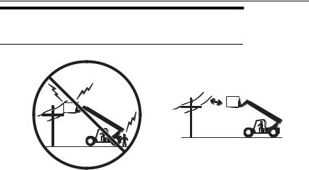
1.3 OPERATION SAFETY
Electrical Hazards
10 FT (3 M)
OW0040
•This machine is not insulated and does not provide protection from contact or being near electrical current.
•NEVER operate the telehandler in an area where overhead power lines, overhead or underground cables, or other power sources may exist without ensuring the appropriate power or utility company de-energizes the lines.
•Always check for power lines before raising the boom.
1-2 |
31200192 |
Section 1 - General Safety Practices
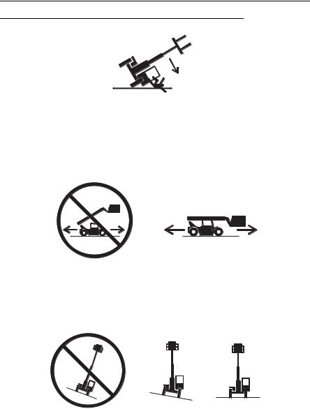
Tip Over Hazard
OW0050
•Never use an attachment without the appropriate JLG supplied capacity chart installed on the telehandler.
•DO NOT exceed rated lift capacity.
•Be sure that the ground conditions are able to support the machine.
OW0060
•DO NOT drive with boom raised.
•When driving in high speed, use only front wheel steer (if steering modes are selectable).
OW0080
• DO NOT raise boom unless frame is level (0 degrees).
31200192 |
1-3 |
Section 1 - General Safety Practices
4 FT
(1,2 M)
OW0100
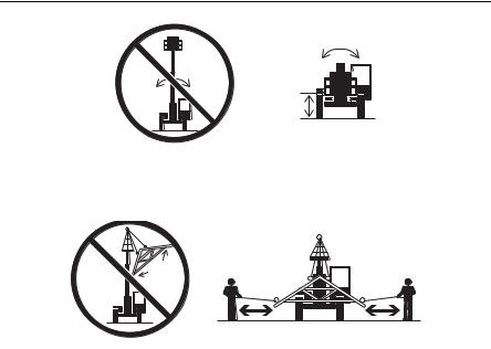
• DO NOT level machine with boom/attachment above 4 ft (1,2 m).
OW0150
•Carry load as low as possible. Tether suspended loads to restrict movement.
•Understand how to properly use the capacity charts located in cab (see page 5-3).
•Weight of all rigging (slings, etc.) must be included as part of load.
•Start, travel, turn and stop slowly to prevent load from swinging.
•Beware of wind. Wind can cause a suspended load to swing and cause dangerous side loads - even with tag lines.
•DO NOT attempt to use telehandler frame-leveling to compensate for load swing.
•Keep heavy part of load closest to attachment.
•Never drag the load; lift vertically.
1-4 |
31200192 |
Section 1 - General Safety Practices
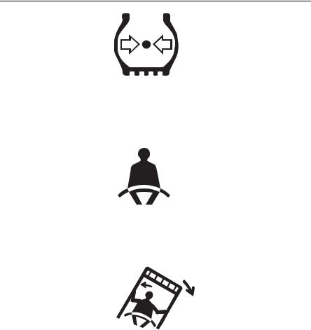
OH2291
•MAINTAIN proper tire pressure at all times. If proper tire pressures are not maintained, this machine could tip over.
•Refer to manufacturer’s specifications for proper fill ratio and pressure requirements for tires equipped with ballast.
OH20911
•Always wear the seat belt.
•Keep head, arms, hands, legs and all other body parts inside operator’s cab at all times.
OH2221
If the telehandler starts to tip over:
•DO NOT JUMP
•BRACE YOURSELF and STAY WITH THE MACHINE
•KEEP YOUR SEAT BELT FASTENED
•HOLD ON FIRMLY
•LEAN AWAY FROM THE POINT OF IMPACT
Trying to escape from a tipping machine could result in death or serious injury.
31200192 |
1-5 |
Section 1 - General Safety Practices
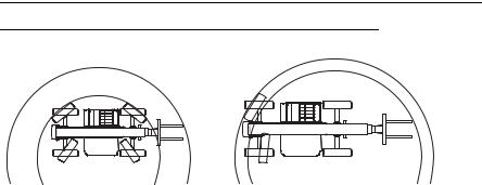
Travel Hazard
4-Wheel Steer |
Pivot Steer |
OW0120 |
•Steering characteristics differ between 4-Wheel Steer & Pivot Steer telehandlers as shown above. Identify the telehandler you are operating & others on the jobsite.
•Ensure that adequate clearance is provided between both rear tail swing and front fork swing.
•Unlike a conventional 4-wheel steer telehandler the rear wheels of a pivot steer telehandler turn a wider circle than the front wheels.
•Look out for and avoid other personnel, machinery and vehicles in the area. Use a spotter if you DO NOT have a clear view.
•Before moving be sure of a clear path and sound horn.
•When driving, retract boom and keep boom/attachment as low as possible while maintaining visibility of mirrors and maximum visibility of path of travel.
•Always look in the direction of travel.
•Always check boom clearances carefully before driving underneath overhead obstructions. Position attachment/load to clear obstacles.
1-6 |
31200192 |

Section 1 - General Safety Practices
Load Falling Hazard
OW0130
•Never suspend load from forks or other parts of carriage.
•DO NOT burn or drill holes in fork(s).
•Forks must be centered under load and spaced apart as far as possible.
31200192 |
1-7 |
Section 1 - General Safety Practices
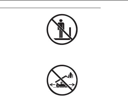
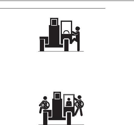
Lifting Personnel
•When lifting personnel, USE ONLY a JLG approved personnel work platform, with proper capacity chart displayed in the cab.
OW0190
• DO NOT drive machine from cab when personnel are in platform.
1-8 |
31200192 |
Section 1 - General Safety Practices
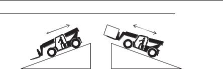
Driving Hazards on Slopes
OW0200
To maintain sufficient traction and braking capabilities, travel on slopes as follows:
•When unloaded, the rear of the machine is the “heavy end.” Drive with forks pointed downhill.
•When loaded, the front of the machine is the “heavy end.” Drive with the forks pointed uphill.
•To avoid overspeeding the engine and drivetrain when driving down slopes, downshift to a lower gear and use the service brake as necessary to maintain a slow speed. DO NOT shift into neutral and coast downhill.
•Avoid excessively steep slopes or unstable surfaces. To avoid tip over DO NOT drive across excessively steep slopes under any circumstances.
•Avoid turning on a slope. Never engage “inching” or shift to “Neutral” when going downhill.
•DO NOT park on a slope.
31200192 |
1-9 |
Section 1 - General Safety Practices
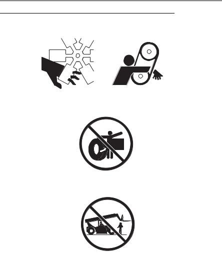
Pinch Points and Crush Hazards
Stay clear of pinch points and rotating parts on the telehandler.
OW0210
• Stay clear of moving parts while engine is running.
• Keep clear of steering tires and frame or other objects.
• Keep clear from under boom.
1-10 |
31200192 |
Section 1 - General Safety Practices
• Keep clear of boom holes.
• Keep arms and hands clear of attachment tilt cylinder.
• Keep hands and fingers clear of carriage and forks.
OW0960
• Keep others away while operating.
31200192 |
1-11 |
Section 1 - General Safety Practices
Fall Hazard
OW0280 |
•Enter using the proper hand holds and steps provided. Always maintain 3-point contact when mounting or dismounting. Never grab control levers or steering wheel when mounting or dismounting the machine.
•DO NOT get off the machine until the shutdown procedure on page 4-3 has been performed.
OW0290
•DO NOT carry riders. Riders could fall off machine causing death or serious injury.
1-12 |
31200192 |
Section 1 - General Safety Practices
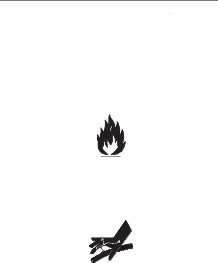
Chemical Hazards
Exhaust Fumes
•DO NOT operate machine in an enclosed area without proper ventilation.
•DO NOT operate the machine in hazardous environments unless approved for that purpose by JLG and site owner. Sparks from the electrical system and the engine exhaust can cause an explosion.
•If spark arrestors are required, ensure they are in place and in good working order.
Flammable Fuel
OW0300
•DO NOT fill the fuel tank or service the fuel system near an open flame, sparks or smoking materials. Engine fuel is flammable and can cause a fire and/or explosion.
Hydraulic Fluid
OW0950
•DO NOT attempt to repair or tighten any hydraulic hoses or fittings while the engine is running or when the hydraulic system is under pressure.
•Stop engine and relieve trapped pressure. Fluid in the hydraulic system is under enough pressure that it can penetrate the skin.
•DO NOT use your hand to check for leaks. Use a piece of cardboard or paper to search for leaks. Wear gloves to protect hands from spraying fluid.
31200192 |
1-13 |

Section 1 - General Safety Practices
This Page Intentionally Left Blank
1-14 |
31200192 |

Section 2 - Pre-Operation and Inspection
SECTION 2 - PRE-OPERATION AND INSPECTION
2.1PRE-OPERATION CHECK AND INSPECTION
Note: Complete all required maintenance before operating unit.
 WARNING
FALL HAZARD. Use extreme caution when checking items beyond your normal reach. Use an approved ladder. Failure to comply could result in death or serious injury.
The pre-operation check & inspection, performed at beginning of each work shift or at each change of operator, should include the following:
1.Cleanliness - Check all surfaces for leakage (oil, fuel or battery fluid) or foreign objects. Report any leakage to the proper maintenance personnel.
2.Structure - Inspect the machine structure for dents, damage, weld or parent metal cracks or other discrepancies.
OAH1000
PARENT METAL CRACK |
WELD CRACK |
3.Safety Decals - Ensure all safety decals are legible and in place. Clean or replace as required. See page 2-3 for details.
4.Operation and Safety Manuals - Operation & Safety Manual and AEM Safety Manual are located in cab manual holder.
5.Walk-Around Inspection - See page 2-6 for details.
6.Fluid Levels - Check fluids, including fuel, brake fluid, hydraulic oil, engine oil and coolant. When adding fluids, refer to Section 7 - Lubrication and Maintenance and Section 9 - Specifications to determine proper type and intervals. Before removing filler caps or fill plugs, wipe all dirt and grease away from the ports. If dirt enters these ports, it can severely reduce component life.
7.Attachments/Accessories - Ensure correct load charts are installed on the telehandler. If provided, reference the Operation & Safety Manual of each attachment or accessory installed for specific inspection, operation and maintenance instructions.
31200192 |
2-1 |

Section 2 - Pre-Operation and Inspection
8.Operational Check - Once the walk-around inspection is complete, perform a warm-up and operational check (see page 2-8) of all systems in an area free of overhead and ground level obstructions. See Section 3 - Controls and Indicators for more specific operating instructions.
 WARNING
If telehandler does not operate properly, immediately bring machine to a stop, lower boom and attachment to ground and stop the engine. Determine cause and correct before continued use.
2-2 |
31200192 |
Section 2 - Pre-Operation and Inspection
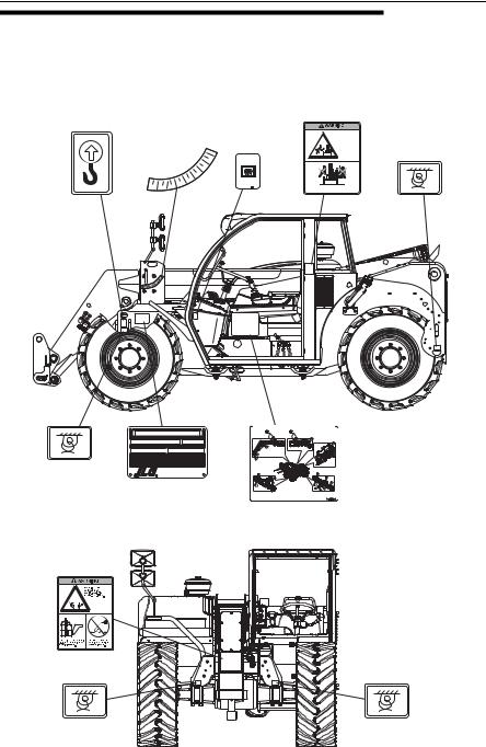
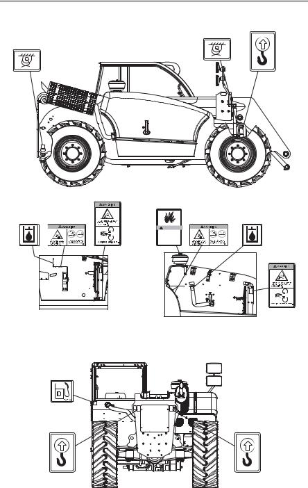
2.2SAFETY DECALS
Ensure all DANGER, WARNING, CAUTION and instructional decals and proper capacity charts are legible and in place. Clean and replace as required.
1701500
1701500
1705998 2447967
|
|
|
|
60° |
O I L |
|
|
|
|
|
50° |
|
|
|
|
|
20 |
40° |
ATF |
9672447 |
|
|
|
30° |
|||
-10° |
0° |
10° |
° |
|
|
|
|
|
D e x r o n D |
|
-10°
1706835
Riders |
|
could |
|
fall off |
|
machine |
|
causing |
1702300 |
death or |
|
serious |
|
injury. |
|
No Riders |
1702300 |
1706835A |
1702300
1702300
(S/N 116002234 & AFTER)
Model
Serial Number |
Year Of Manufacture |
Maximum Weight Without Attachments (lbs/kg) |
Maximum Capacity (lbs/kg) |
° Refer to load capacity chart for truck with attachment, and individual load ratings stamped on forks, if equipped. Use lowest capacity of all ratings.
As released from factory this truck meets specifications in ASME B56.6-2002 Part III.
One or more of the following patents may apply to this truck; U.S. Nos. 4,954,041 6,349,969 5,639,119 5,813,697 5,230,399 5,052,532. Other patents pending.
1706910 A
Manufactured by
JLG Manufacturing Europe BVBA
Industrieterrein Oude Bunders 1034, Breitwaterstraat 12 3630 Maasmechelen - Belgium
1706910
 OAH0921
1706391
1706298 |
1702300 |
1702300 |
1702300 |
1702300 |
(BEFORE |
(BEFORE |
S/N 116002234) |
S/N 116002234) |
OAH0802
31200192 |
2-3 |
Section 2 - Pre-Operation and Inspection
1702300
1702300
1706301
1701504 1706297
1701504 A |
1706297A |
1706301A |
VIEW OF ENGINE COMPARTMENT
WITH ENGINE REMOVED
(BEFORE S/N 116002380)
8009815
1701500
1701500
1704972
! WARNING
EXPLOSION/FIRE HAZARD
 Do not use starting fluid. This unit is equipped with an
air intake heater or glow plugs.
Failure to follow instructions could result in death or serious injury.
1704972 C
(S/N 116002234 |
|
& AFTER) |
1701500 |
1702300 |
|
1702300
1701500
1706297 1701504
1706297A |
1701504 A |
1706301
1706301A
VIEW OF ENGINE COMPARTMENT
WITH ENGINE REMOVED
(S/N 116002380 & AFTER)
1701500
1701500
OAH0811
2-4 |
31200192 |

Section 2 - Pre-Operation and Inspection
1706306
1706306
1706299
CONTACTING |
1706299 |
POWER LINES |
|
will result in death |
|
or serious injury. |
|
|
1706299A |
CONTACTING |
POWER LINES |
will result in death |
or serious injury. |
1706850 |
 WARNING
CRUSHING HAZARD |
Keep others |
|
|
|
1706850 |
1706850A |
|
|
|
Lowering boom or falling load could |
away while |
|
|
|
cause death or serious injury. |
operating. |
|
|
|
WARNING |
|
|
|
|
Lowering boom1706303or falling load could |
away while |
|
|
|
CRUSHING HAZARD |
Keep others |
|
|
|
cause death or serious injury. |
operating. |
|
|
|
Operator must be trained1706850Aand |
belt. |
1706303A |
||
and safety manuals. |
|
|||
must read and understand |
|
Fasten |
|
|
all capacity charts, operator |
|
seat |
|
|
1706303 |
|
|
|
|
Operator must be trained and |
belt. |
1706303A |
|
|
and safety manuals. |
|
|||
must read and understand |
Fasten |
|
|
|
all capacity charts, operator |
seat |
|
|
|
1706306A
1706306A
1706304
RUN-OVER 1706767 HAZARD
could cause
death or |
|
1706304 |
|
serious |
|
injury. |
|
could cause |
1706767 |
RUN-OVER |
|
HAZARD |
|
death or |
|
serious |
1706767A |
1706304A |
|
injury. |
|
1706944
(Standard)
 1706944
 (Standard)
1706944A
1706951
(Optional)
 1706951
 (Optional)
1706951A
1706299A |
1706767A |
|
1706851 |
1706304A |
1706944A |
1706951A |


 1706851


 1706851A


 1706851A
VIEW OF DECALS LOCATED INSIDE CAB
ON RIGHT HAND WINDOW
(BEFORE S/N 116002380)
1707078
CONTACTING POWER LINES will result in death or serious injury.
DO NOT place machine or load within 10 feet (3m) of power lines.
Operator |
|
|
|
must be trained and |
|
Fasten |
|
must read and understand |
|
||
all capacity charts, operator |
|
seat |
|
and safety manuals. |
|
belt. |
|
 WARNING
LOWERING BOOM or |
Keep others |
|
FALLING LOAD |
|
away while |
can crush causing death |
|
operating. |
or serious injury. |
|
|
RUN-OVER |
HAZARD |
could cause |
death or |
serious |
injury. |
MACHINE ROLL-AWAY could cause death or  serious injury.
JUMPING OFF of a tipping machine could result in death or serious injury.
1707078A
1706944 |
1706951 |
(Standard) |
(Optional) |
1706944A |
1706951A |
XXXXX
28'
24'
170620916'0' 40° 50°
|
|
|
|
|
|
s |
|
|
|
|
|
|
b |
|
|
|
|
|
|
l |
|
|
30° |
|
|
s |
0 |
12' |
|
|
|
|
l |
6 |
|
|
|
|
s 0 4 |
||
|
|
|
|
b 0 |
|
|
|
|
|
|
l |
0 |
|
|
20° |
s 0 |
4 |
|
||
8' |
|
|
l |
5 |
|
|
|
|
s |
0 |
3 |
|
|
|
|
b |
|
|
|
|
|
|
l |
0 |
|
|
|
|
10° |
0 |
0 |
|
|
|
4' |
0 |
3 |
|
|
|
|
|
5 |
|
|
|
|
|
|
|
2 |
|
|
|
|
0' |
0° |
|
|
|
|
|
-4'16' |
|
12' |
|
|
8' |
|
60°
s |
|
b |
|
l |
|
0 |
|
0 |
|
6 |
6600 |
5 |
|
|
4' |
 24”
24”
C
B
A
lbs
0'
LOAD |
9116-3028 |
|
|
CHARTS |
|
VIEW OF DECALS LOCATED INSIDE CAB
ON RIGHT HAND WINDOW
(S/N 1160002380 & AFTER)
VIEW OF PARK |
|
|
BRAKE LEVER |
|
|
1706463 |
8005870 |
|
1706463 |
||
8005870 |
||
|
8005870
8005870
VIEW OF REAR WINDOW
|
LOAD |
91163028 |
1706801 |
1706859 |
||||||||
|
|
|||||||||||
CHARTS |
|
|
|
|||||||||
|
XXXXX |
|
|
|
||||||||
28' |
|
|
|
|
|
|
|
|
|
|
|
|
|
|
|
|
|
|
|
|
|
24” |
|
|
|
24' |
|
|
|
|
|
|
60° |
|
|
1706801A |
1706859A |
|
|
|
|
|
|
|
|
|
|
|
|
||
|
|
|
|
|
|
|
|
|
C |
|
|
|
20' |
|
|
|
|
50° |
|
|
B |
|
|
|
|
|
|
|
|
|
|
|
b |
|
A |
|
|
|
16' |
|
|
40° |
|
|
s |
|
|
|
|
|
|
|
|
|
|
|
|
l |
6 |
|
lbs |
|
|
|
|
|
|
|
|
|
s 0 |
|
|
|
|
|
|
|
|
|
|
s 0 |
b |
0 |
6600 |
|
|
|
|
|
|
|
|
|
4 |
|
|
|
|
|
|||
|
|
30° |
|
|
s |
0 |
5 |
|
|
|
|
|
12' |
|
|
|
|
l |
6 |
|
|
|
|
|
|
|
|
|
|
b |
0 |
|
|
|
|
|
|
|
|
|
|
|
l |
0 |
|
|
|
|
|
|
|
|
20° |
s 0 |
4 |
|
|
|
|
|
|
|
||
8' |
|
|
l |
5 |
|
|
|
|
|
|
|
|
|
|
s |
0 |
3 |
|
|
|
|
|
|
|
|
|
|
b |
|
|
|
|
|
|
|
|
|
|
|
|
l |
0 |
|
|
|
|
|
|
|
|
|
|
10° |
0 |
0 |
|
|
|
|
|
|
|
|
|
4' |
|
5 |
|
|
|
|
|
|
|
|
|
|
|
|
2 |
|
|
|
|
|
|
|
|
|
|
0' |
0° |
|
|
|
|
|
|
|
|
|
|
|
-4'16' |
|
12' |
|
|
8' |
|
|
4' |
0' |
|
|
|
1706209
OAH0821
OAH0822
TOP VIEW OF DASH
31200192 |
2-5 |
Section 2 - Pre-Operation and Inspection
2.3WALK-AROUND INSPECTION
|
|
13 |
|
|
1 |
|
2 |
12 |
|
|
|
3 |
|
4 |
4 11
11
 10 5
10 5 
9
6
4 |
7 |
8 |
4 |
OAH0790 |
Begin your walk-around inspection at item 1, as noted below. Continue to your right (counterclockwise when viewed from top) checking each item in sequence.
INSPECTION NOTE: On all components, make sure there are no loose or missing parts, that they are securely fastened and no visible leaks or excessive wear exists in addition to any other criteria mentioned. Inspect all structural members including attachment for cracks, excessive corrosion and other damage.
1.Boom Sections & Lift, Tilt, Extend/Retract, Compensating (Slave) Cylinders -
•Check front, top, side & rear slider pads for adequate grease.
•Pivot pins secure; hydraulic hoses undamaged, not leaking.
2.Front Axle - Steer cylinders undamaged, not leaking; hydraulic hoses undamaged, not leaking.
2-6 |
31200192 |
Loading...