


 Loading...
Service Manual
Models G5-18A
&
2505
31200361
Original
February 28, 2008
An Oshkosh Truck Corporation Company
EFFECTIVITY PAGE
February 28, 2008 - A - Original Issue Of Manual
31200361 |
G5-18A/2505 |
a |
EFFECTIVITY PAGE
-b |
G5-18A/2505 |
31200361 |

SECTION CONTENTS
Section Subject Page
Section 1 |
|
|
Safety Practices . . . . . . . . . . . . . . . . . . . . . . . . . . . . . . . . . . . . . . . . . . . . . . . . . . . . . . . |
1.1 |
|
1.1 |
Introduction . . . . . . . . . . . . . . . . . . . . . . . . . . . . . . . . . . . . . . . . . . . . . . . . . . . . . . . . . . |
1.2 |
1.2 |
Disclaimer . . . . . . . . . . . . . . . . . . . . . . . . . . . . . . . . . . . . . . . . . . . . . . . . . . . . . . . . . . . |
1.2 |
1.3 |
Operation & Safety Manual . . . . . . . . . . . . . . . . . . . . . . . . . . . . . . . . . . . . . . . . . . . . . . |
1.2 |
1.4 |
Do Not Operate Tags . . . . . . . . . . . . . . . . . . . . . . . . . . . . . . . . . . . . . . . . . . . . . . . . . . . |
1.2 |
1.5 |
Safety Information . . . . . . . . . . . . . . . . . . . . . . . . . . . . . . . . . . . . . . . . . . . . . . . . . . . . . |
1.3 |
1.6 |
Safety Instructions . . . . . . . . . . . . . . . . . . . . . . . . . . . . . . . . . . . . . . . . . . . . . . . . . . . . . |
1.3 |
1.7 |
Safety Decals . . . . . . . . . . . . . . . . . . . . . . . . . . . . . . . . . . . . . . . . . . . . . . . . . . . . . . . . . |
1.4 |
Section 2 |
|
|
General Information and Specifications . . . . . . . . . . . . . . . . . . . . . . . . . . . . . . . . . . . . |
2.1 |
|
2.1 |
Replacement Parts and Warranty Information . . . . . . . . . . . . . . . . . . . . . . . . . . . . . . . . |
2.2 |
2.2 |
Torques . . . . . . . . . . . . . . . . . . . . . . . . . . . . . . . . . . . . . . . . . . . . . . . . . . . . . . . . . . . . . |
2.3 |
2.3 |
Specifications . . . . . . . . . . . . . . . . . . . . . . . . . . . . . . . . . . . . . . . . . . . . . . . . . . . . . . . . . |
2.6 |
2.4 |
Fluids, Lubricants and Capacities . . . . . . . . . . . . . . . . . . . . . . . . . . . . . . . . . . . . . . . . . |
2.8 |
2.5 |
Maintenance Schedules. . . . . . . . . . . . . . . . . . . . . . . . . . . . . . . . . . . . . . . . . . . . . . . . . |
2.9 |
2.6 |
Lubrication Schedule . . . . . . . . . . . . . . . . . . . . . . . . . . . . . . . . . . . . . . . . . . . . . . . . . . . |
2.10 |
Section 3 |
|
|
Boom . . |
. . . . . . . . . . . . . . . . . . . . . . . . . . . . . . . . . . . . . . . . . . . . . . . . . . . . . . . . . |
3.1 |
3.1 |
Boom System Component Terminology. . . . . . . . . . . . . . . . . . . . . . . . . . . . . . . . . . . . . |
3.2 |
3.2 |
Boom System - Two Section Boom . . . . . . . . . . . . . . . . . . . . . . . . . . . . . . . . . . . . . . . . |
3.3 |
3.3 |
Boom Assembly Maintenance . . . . . . . . . . . . . . . . . . . . . . . . . . . . . . . . . . . . . . . . . . . . |
3.3 |
3.4 |
Boom Wear Pads . . . . . . . . . . . . . . . . . . . . . . . . . . . . . . . . . . . . . . . . . . . . . . . . . . . . . . |
3.10 |
3.5 |
Quick Attach Assembly . . . . . . . . . . . . . . . . . . . . . . . . . . . . . . . . . . . . . . . . . . . . . . . . . |
3.11 |
3.6 |
Troubleshooting . . . . . . . . . . . . . . . . . . . . . . . . . . . . . . . . . . . . . . . . . . . . . . . . . . . . . . . |
3.14 |
Section 4 |
|
|
Cab and Covers . . . . . . . . . . . . . . . . . . . . . . . . . . . . . . . . . . . . . . . . . . . . . . . . . . . . . . . . |
4.1 |
|
4.1 |
Operator’s Cab and Covers Component Terminology . . . . . . . . . . . . . . . . . . . . . . . . . . |
4.2 |
4.2 |
Operator’s Cab . . . . . . . . . . . . . . . . . . . . . . . . . . . . . . . . . . . . . . . . . . . . . . . . . . . . . . . . |
4.3 |
4.3 |
Cab Components . . . . . . . . . . . . . . . . . . . . . . . . . . . . . . . . . . . . . . . . . . . . . . . . . . . . . . |
4.3 |
4.4 |
Cab Removal . . . . . . . . . . . . . . . . . . . . . . . . . . . . . . . . . . . . . . . . . . . . . . . . . . . . . . . . . |
4.8 |
4.5 |
Cab Installation . . . . . . . . . . . . . . . . . . . . . . . . . . . . . . . . . . . . . . . . . . . . . . . . . . . . . . . |
4.9 |
Section 5 |
|
|
Axles, Drive Shafts, Wheels and Tires . . . . . . . . . . . . . . . . . . . . . . . . . . . . . . . . . . . . . |
5.1 |
|
5.1 |
Axle, Drive Shaft and Wheel Component Terminology . . . . . . . . . . . . . . . . . . . . . . . . . |
5.2 |
5.2 |
General Information . . . . . . . . . . . . . . . . . . . . . . . . . . . . . . . . . . . . . . . . . . . . . . . . . . . . |
5.3 |
5.3 |
Axle Assemblies. . . . . . . . . . . . . . . . . . . . . . . . . . . . . . . . . . . . . . . . . . . . . . . . . . . . . . . |
5.3 |
5.4 |
Drive Shafts . . . . . . . . . . . . . . . . . . . . . . . . . . . . . . . . . . . . . . . . . . . . . . . . . . . . . . . . . . |
5.9 |
5.5 |
Wheels and Tires . . . . . . . . . . . . . . . . . . . . . . . . . . . . . . . . . . . . . . . . . . . . . . . . . . . . . . |
5.10 |
5.6 |
Steering Adjustment. . . . . . . . . . . . . . . . . . . . . . . . . . . . . . . . . . . . . . . . . . . . . . . . . . . . |
5.11 |
5.7 |
Brakes . . . . . . . . . . . . . . . . . . . . . . . . . . . . . . . . . . . . . . . . . . . . . . . . . . . . . . . . . . . . . . |
5.11 |
G5-18A, 2505 |
i |

Section Subject Page
Section 6 |
|
|
Transmission . |
. . . . . . . . . . . . . . . . . . . . . . . . . . . . . . . . . . . . . . . . . . . . . . . . . . . . . . . . . |
6.1 |
6.1 |
Transmission Assembly Component Terminology . . . . . . . . . . . . . . . . . . . . . . . . . . . . . |
6.2 |
6.2 |
Transmission Description . . . . . . . . . . . . . . . . . . . . . . . . . . . . . . . . . . . . . . . . . . . . . . . . |
6.3 |
6.3 |
Transmission Specifications . . . . . . . . . . . . . . . . . . . . . . . . . . . . . . . . . . . . . . . . . . . . . . |
6.3 |
6.4 |
Transmission Replacement . . . . . . . . . . . . . . . . . . . . . . . . . . . . . . . . . . . . . . . . . . . . . . |
6.3 |
6.5 |
Transmission Filter Replacement . . . . . . . . . . . . . . . . . . . . . . . . . . . . . . . . . . . . . . . . . . |
6.5 |
6.6 |
Towing a Disabled Machine . . . . . . . . . . . . . . . . . . . . . . . . . . . . . . . . . . . . . . . . . . . . . . |
6.6 |
Section 7 |
|
|
Engine: Perkins 1104D-44T . . . . . . . . . . . . . . . . . . . . . . . . . . . . . . . . . . . . . . . . . . . . . . . |
7.1 |
|
7.1 |
Introduction . . . . . . . . . . . . . . . . . . . . . . . . . . . . . . . . . . . . . . . . . . . . . . . . . . . . . . . . . . |
7.2 |
7.2 |
Engine Serial Number . . . . . . . . . . . . . . . . . . . . . . . . . . . . . . . . . . . . . . . . . . . . . . . . . . |
7.4 |
7.3 |
Specifications and Maintenance Information . . . . . . . . . . . . . . . . . . . . . . . . . . . . . . . . . |
7.4 |
7.4 |
Engine Cooling System . . . . . . . . . . . . . . . . . . . . . . . . . . . . . . . . . . . . . . . . . . . . . . . . . |
7.4 |
7.5 |
Engine Electrical System . . . . . . . . . . . . . . . . . . . . . . . . . . . . . . . . . . . . . . . . . . . . . . . . |
7.5 |
7.6 |
Fuel System . . . . . . . . . . . . . . . . . . . . . . . . . . . . . . . . . . . . . . . . . . . . . . . . . . . . . . . . . . |
7.5 |
7.7 |
Engine Exhaust and Air Cleaner System . . . . . . . . . . . . . . . . . . . . . . . . . . . . . . . . . . . . |
7.7 |
7.8 |
Engine Replacement . . . . . . . . . . . . . . . . . . . . . . . . . . . . . . . . . . . . . . . . . . . . . . . . . . . |
7.7 |
7.9 |
Engine Coupler . . . . . . . . . . . . . . . . . . . . . . . . . . . . . . . . . . . . . . . . . . . . . . . . . . . . . . . |
7.9 |
7.10 |
Troubleshooting . . . . . . . . . . . . . . . . . . . . . . . . . . . . . . . . . . . . . . . . . . . . . . . . . . . . . . . |
7.10 |
Section 8 |
|
|
Hydraulic System . . . . . . . . . . . . . . . . . . . . . . . . . . . . . . . . . . . . . . . . . . . . . . . . . . . . . . . |
8.1 |
|
8.1 |
Hydraulic Component Terminology . . . . . . . . . . . . . . . . . . . . . . . . . . . . . . . . . . . . . . . . |
8.3 |
8.2 |
Safety Information . . . . . . . . . . . . . . . . . . . . . . . . . . . . . . . . . . . . . . . . . . . . . . . . . . . . . |
8.4 |
8.3 |
Specifications . . . . . . . . . . . . . . . . . . . . . . . . . . . . . . . . . . . . . . . . . . . . . . . . . . . . . . . . . |
8.4 |
8.4 |
Hoses, Tube Lines, Fittings, Etc. . . . . . . . . . . . . . . . . . . . . . . . . . . . . . . . . . . . . . . . . . . |
8.4 |
8.5 |
Hydraulic Pressure Diagnosis . . . . . . . . . . . . . . . . . . . . . . . . . . . . . . . . . . . . . . . . . . . . |
8.5 |
8.6 |
Hydraulic Schematics. . . . . . . . . . . . . . . . . . . . . . . . . . . . . . . . . . . . . . . . . . . . . . . . . . . |
8.8 |
8.7 |
Hydraulic Reservoir . . . . . . . . . . . . . . . . . . . . . . . . . . . . . . . . . . . . . . . . . . . . . . . . . . . . |
8.11 |
8.8 |
Hydraulic System Pump. . . . . . . . . . . . . . . . . . . . . . . . . . . . . . . . . . . . . . . . . . . . . . . . . |
8.11 |
8.9 |
Front Drive Motor . . . . . . . . . . . . . . . . . . . . . . . . . . . . . . . . . . . . . . . . . . . . . . . . . . . . . . |
8.13 |
8.10 |
Valves and Manifolds . . . . . . . . . . . . . . . . . . . . . . . . . . . . . . . . . . . . . . . . . . . . . . . . . . . |
8.14 |
8.11 |
Hydraulic Cylinders . . . . . . . . . . . . . . . . . . . . . . . . . . . . . . . . . . . . . . . . . . . . . . . . . . . . |
8.23 |
Section 9 |
|
|
Electrical System . . . . . . . . . . . . . . . . . . . . . . . . . . . . . . . . . . . . . . . . . . . . . . . . . . . . . . . |
9.1 |
|
9.1 |
Electrical Component Terminology. . . . . . . . . . . . . . . . . . . . . . . . . . . . . . . . . . . . . . . . . |
9.2 |
9.2 |
Specifications . . . . . . . . . . . . . . . . . . . . . . . . . . . . . . . . . . . . . . . . . . . . . . . . . . . . . . . . . |
9.3 |
9.3 |
Fuses and Relays . . . . . . . . . . . . . . . . . . . . . . . . . . . . . . . . . . . . . . . . . . . . . . . . . . . . . |
9.3 |
9.4 |
Electrical System Schematics . . . . . . . . . . . . . . . . . . . . . . . . . . . . . . . . . . . . . . . . . . . . |
9.6 |
9.5 |
Circuit Breakdowns . . . . . . . . . . . . . . . . . . . . . . . . . . . . . . . . . . . . . . . . . . . . . . . . . . . . |
9.11 |
9.6 |
Engine Start Circuit . . . . . . . . . . . . . . . . . . . . . . . . . . . . . . . . . . . . . . . . . . . . . . . . . . . . |
9.15 |
9.7 |
Charging Circuit . . . . . . . . . . . . . . . . . . . . . . . . . . . . . . . . . . . . . . . . . . . . . . . . . . . . . . . |
9.16 |
9.8 |
Electrical System Components . . . . . . . . . . . . . . . . . . . . . . . . . . . . . . . . . . . . . . . . . . . |
9.17 |
9.9 |
Window Wiper/Washer. . . . . . . . . . . . . . . . . . . . . . . . . . . . . . . . . . . . . . . . . . . . . . . . . . |
9.19 |
9.10 |
Cab Heater and Fan. . . . . . . . . . . . . . . . . . . . . . . . . . . . . . . . . . . . . . . . . . . . . . . . . . . . |
9.20 |
9.11 |
Switches, Solenoids and Senders . . . . . . . . . . . . . . . . . . . . . . . . . . . . . . . . . . . . . . . . . |
9.21 |
ii |
G5-18A, 2505 |

Section 1
Safety Practices
Contents
PARAGRAPH |
TITLE |
PAGE |
|
1.1 |
Introduction . . . . . . . . . . . . . . . . . . . . . . . . . . . . . . . . . . . . . . . . . . . . . . . . . . . . . . . |
1.2 |
|
1.2 |
Disclaimer . . . . . . . . . . . . . . . . . . . . . . . . . . . . . . . . . . . . . . . . . . . . . . . . . . . . . . . . |
1.2 |
|
1.3 |
Operation & Safety Manual. . . . . . . . . . . . . . . . . . . . . . . . . . . . . . . . . . . . . . . . . . . |
1.2 |
|
1.4 |
Do Not Operate Tags. . . . . . . . . . . . . . . . . . . . . . . . . . . . . . . . . . . . . . . . . . . . . . . . |
1.2 |
|
1.5 |
Safety Information. . . . . . . . . . . . . . . . . . . . . . . . . . . . . . . . . . . . . . . . . . . . . . . . . . |
1.3 |
|
|
1.5.1 |
Safety Alert System and Signal Words . . . . . . . . . . . . . . . . . . . . . . . . . . . |
1.3 |
1.6 |
Safety Instructions . . . . . . . . . . . . . . . . . . . . . . . . . . . . . . . . . . . . . . . . . . . . . . . . . |
1.3 |
|
|
1.6.1 |
Personal Hazards . . . . . . . . . . . . . . . . . . . . . . . . . . . . . . . . . . . . . . . . . . . |
1.3 |
|
1.6.2 |
Equipment Hazards. . . . . . . . . . . . . . . . . . . . . . . . . . . . . . . . . . . . . . . . . . |
1.3 |
|
1.6.3 |
General Hazards . . . . . . . . . . . . . . . . . . . . . . . . . . . . . . . . . . . . . . . . . . . . |
1.4 |
|
1.6.4 |
Operational Hazards . . . . . . . . . . . . . . . . . . . . . . . . . . . . . . . . . . . . . . . . . |
1.4 |
1.7 |
Safety Decals. . . . . . . . . . . . . . . . . . . . . . . . . . . . . . . . . . . . . . . . . . . . . . . . . . . . . . |
1.4 |
|
G5-18A/2505 |
1.1 |

Safety Practices
1.1INTRODUCTION
This service manual provides general directions for accomplishing service and repair procedures. Following the procedures in this manual will help assure safety and equipment reliability.
Read, understand and follow the information in this manual, and obey all locally approved safety practices, procedures, rules, codes, regulations and laws.
These instructions cannot cover all details or variations in the equipment, procedures, or processes described, nor provide directions for meeting every possible contingency during operation, maintenance, or testing. When additional information is desired consult the local JLG distributor.
Many factors contribute to unsafe conditions: carelessness, fatigue, overload, inattentiveness, unfamiliarity, even drugs and alcohol, among others. For optimal safety, encourage everyone to think, and to act, safely.
Appropriate service methods and proper repair procedures are essential for the safety of the individual doing the work, for the safety of the operator, and for the safe, reliable operation of the machine. All references to the right side, left side, front and rear are given from the operator’s seat looking in a forward direction.
Supplementary information is available from JLG in the form of Service Bulletins, Service Campaigns, Service Training Schools, the JLG website, other literature, and through updates to the manual itself.
1.2
1.2DISCLAIMER
All information in this manual is based on the latest product information available at the time of publication. JLG reserves the right to make changes and improvements to its products, and to discontinue the manufacture of any product, at its discretion at any time without public notice or obligation.
1.3OPERATION & SAFETY MANUAL
The mechanic must not operate the machine until the Operation & Safety Manual has been read & understood, training has been accomplished and operation of the machine has been completed under the supervision of an experienced and qualified operator.
An Operation & Safety Manual is supplied with each machine and must be kept in the cab. In the event that the Operation & Safety Manual is missing, consult the local JLG distributor before proceeding.
1.4DO NOT OPERATE TAGS
Place Do Not Operate Tags on the ignition key switch and the steering wheel before attempting to perform any service or maintenance. Remove key and disconnect battery leads.
G5-18A/2505

Safety Practices
1.5SAFETY INFORMATION
To avoid possible death or injury, carefully read, understand and comply with all safety messages.
In the event of an accident, know where to obtain medical assistance and how to use a first-aid kit and fire extinguisher/fire suppression system. Keep emergency telephone numbers (fire department, ambulance, rescue squad/paramedics, police department, etc.) nearby. If working alone, check with another person routinely to help assure personal safety.
1.5.1Safety Alert System and Signal Words
 DANGER
DANGER indicates an imminently hazardous situation which, if not avoided, will result in death or serious injury.
 WARNING
WARNING indicates a potentially hazardous situation which, if not avoided, could result in death or serious injury.
 CAUTION
CAUTION indicates a potentially hazardous situation which, if not avoided, may result in minor or moderate injury.
G5-18A/2505
1.6SAFETY INSTRUCTIONS
Following are general safety statements to consider before performing maintenance procedures on the telehandler. Additional statements related to specific tasks and procedures are located throughout this manual and are listed prior to any work instructions to provide safety information before the potential of a hazard occurs.
For all safety messages, carefully read, understand and follow the instructions before proceeding.
1.6.1Personal Hazards
PERSONAL SAFETY GEAR: Wear all the protective clothing and personal safety gear necessary to perform the job safely. This might include heavy gloves, safety glasses or goggles, filter mask or respirator, safety shoes or a hard hat.
LIFTING: NEVER lift a heavy object without the help of at least one assistant or a suitable sling and hoist.
1.6.2Equipment Hazards
LIFTING OF EQUIPMENT: Before using any lifting equipment (chains, slings, brackets, hooks, etc.), verify that it is of the proper capacity, in good working order, and is properly attached.
NEVER stand or otherwise become positioned under a suspended load or under raised equipment. The load or equipment could fall or tip.
DO NOT use a hoist, jack or jack stands only to support equipment. Always support equipment with the proper capacity blocks or stands properly rated for the load.
HAND TOOLS: Always use the proper tool for the job; keep tools clean and in good working order, and use special service tools only as recommended.
1.3

Safety Practices
1.6.3General Hazards
SOLVENTS: Only use approved solvents that are known to be safe for use.
HOUSEKEEPING: Keep the work area and operator’s cab clean, and remove all hazards (debris, oil, tools, etc.).
FIRST AID: Immediately clean, dress and report all injuries (cuts, abrasions, burns, etc.), no matter how minor the injury may seem. Know the location of a First Aid Kit, and know how to use it.
CLEANLINESS: Wear eye protection, and clean all components with a high-pressure or steam cleaner before attempting service.
When removing hydraulic components, plug hose ends and connections to prevent excess leakage and contamination. Place a suitable catch basin beneath the machine to capture fluid run-off.
Check and obey all Federal, State and/or Local regulations regarding waste storage, disposal and recycling.
1.6.4Operational Hazards
ENGINE: Stop the engine before performing any service unless specifically instructed otherwise.
VENTILATION: Avoid prolonged engine operation in enclosed areas without adequate ventilation.
SOFT SURFACES AND SLOPES: NEVER work on a machine that is parked on a soft surface or slope. The machine must be on a hard level surface, with the wheels blocked before performing any service.
FLUID TEMPERATURE: NEVER work on a machine when the engine, cooling or hydraulic systems are hot. Hot components and fluids can cause severe burns. Allow systems to cool before proceeding.
FLUID PRESSURE: Before loosening any hydraulic or diesel fuel component, hose or tube, turn the engine OFF. Wear heavy, protective gloves and eye protection. NEVER check for leaks using any part of your body; use a piece of cardboard or wood instead. If injured, seek medical attention immediately. Diesel fluid leaking under pressure can explode. Hydraulic fluid and diesel fuel leaking under pressure can penetrate the skin, cause infection, gangrene and other serious personal injury.
Relieve all pressure before disconnecting any component, part, line or hose. Slowly loosen parts and allow release of residual pressure before removing any part or component. Before starting the engine or applying pressure, use components, parts, hoses and pipes that are in good condition, connected properly and are tightened to the proper torque. Capture fluid in an
appropriate container and dispose of in accordance with prevailing environmental regulations.
RADIATOR CAP: Always wear steam-resistant, heat protective gloves when opening the radiator cap. Cover the cap with a clean, thick cloth and turn slowly to the first stop to relieve pressure.
FLUID FLAMABILTITY: DO NOT service the fuel or hydraulic systems near an open flame, sparks or smoking materials.
NEVER drain or store fluids in an open container. Engine fuel and hydraulic fluid are flammable and can cause a fire and/or explosion.
DO NOT mix gasoline or alcohol with diesel fuel. The mixture can cause an explosion.
PRESSURE TESTING: When conducting any test, only use test equipment that is correctly calibrated and in good condition. Use the correct equipment in the proper manner, and make changes or repairs as indicated by the test procedure to achieve the desired result.
LEAVING MACHINE: Lower the forks or attachment to the ground before leaving the machine.
TIRES: Always keep tires inflated to the proper pressure to help prevent tipover. DO NOT over-inflate tires.
NEVER use mismatched tire types, sizes or ply ratings. Always use matched sets according to machine specifications.
MAJOR COMPONENTS: Never alter, remove, or substitute any items such as counterweights, tires, batteries or other items that may reduce or affect the overall weight or stability of the machine.
BATTERY: DO NOT charge a frozen battery.Charging a frozen battery may cause it to explode. Allow the battery to thaw before jump-starting or connecting a battery charger.
1.7SAFETY DECALS
Check that all safety decals are present and readable on the machine. Refer to the Operation & Safety Manual supplied with machine for information.
1.4 |
G5-18A/2505 |
Section 2
General Information and Specifications
Contents
PARAGRAPH |
TITLE |
PAGE |
|
2.1 |
Replacement Parts and Warranty Information . . . . . . . . . . . . . . . . . . . . . . . . . . . |
2.2 |
|
2.2 |
Torques. |
. . . . . . . . . . . . . . . . . . . . . . . . . . . . . . . . . . . . . . . . . . . . . . . . . . . . . . . . . . |
2.3 |
|
2.2.1 |
ASTM Fastener Torque Chart (English) . . . . . . . . . . . . . . . . . . . . . . . . . . |
2.3 |
|
2.2.2 |
ASTM Fastener Torque Chart (Metric) . . . . . . . . . . . . . . . . . . . . . . . . . . . |
2.4 |
|
2.2.3 |
Metric Fastener Torque Chart . . . . . . . . . . . . . . . . . . . . . . . . . . . . . . . . . . |
2.5 |
2.3 |
Specifications . . . . . . . . . . . . . . . . . . . . . . . . . . . . . . . . . . . . . . . . . . . . . . . . . . . . . |
2.6 |
|
|
2.3.1 |
Travel Speed . . . . . . . . . . . . . . . . . . . . . . . . . . . . . . . . . . . . . . . . . . . . . . . |
2.6 |
|
2.3.2 |
Hydraulic Cylinder Performance Specifications. . . . . . . . . . . . . . . . . . . . . |
2.6 |
|
2.3.3 |
Electrical System. . . . . . . . . . . . . . . . . . . . . . . . . . . . . . . . . . . . . . . . . . . . |
2.6 |
|
2.3.4 |
Engine Performance Specifications. . . . . . . . . . . . . . . . . . . . . . . . . . . . . . |
2.7 |
|
2.3.5 |
Tires . . . . . . . . . . . . . . . . . . . . . . . . . . . . . . . . . . . . . . . . . . . . . . . . . . . . . |
2.7 |
2.4 |
Fluids, Lubricants and Capacities . . . . . . . . . . . . . . . . . . . . . . . . . . . . . . . . . . . . . |
2.8 |
|
2.5 |
Maintenance Schedules . . . . . . . . . . . . . . . . . . . . . . . . . . . . . . . . . . . . . . . . . . . . . |
2.9 |
|
|
2.5.1 |
10,1st 50 & 50 Hour Maintenance Schedule. . . . . . . . . . . . . . . . . . . . . . . |
2.9 |
|
2.5.2 |
1st 250, 250, 500 & 1000 Hour Maintenance Schedule . . . . . . . . . . . . . . |
2.9 |
2.6 |
Lubrication Schedule . . . . . . . . . . . . . . . . . . . . . . . . . . . . . . . . . . . . . . . . . . . . . . . |
2.10 |
|
|
2.6.1 |
250 Hour Lubrication Schedule . . . . . . . . . . . . . . . . . . . . . . . . . . . . . . . . . |
2.10 |
G5-18A/2505 |
2.1 |
General Information and Specifications
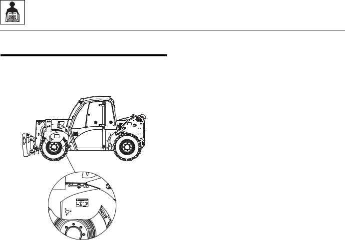
2.1REPLACEMENT PARTS AND WARRANTY INFORMATION
Before ordering parts or initiating service inquiries, make note of the machine serial number. The machine serial number plate is located as indicated in the figure.
MY2350
IMPORTANT: The replacement of any part on this machine with any other than a JLG authorized replacement part can adversely affect the performance, durability, or safety of the machine, and will void the warranty. JLG disclaims liability for any claims or damages, whether regarding property damage, personal injury or death arising out of the use of unauthorized replacement parts.
A warranty registration form must be filled out by the JLG distributor, signed by the purchaser and returned to JLG when the machine is sold and/or put into use.
Registration activates the warranty period and helps to assure that warranty claims are promptly processed. To guarantee full warranty service, verify that the distributor has returned the business reply card of the warranty registration form to JLG.
2.2 |
G5-18A/2505 |

18A/2505-G5 |
40 |
|
0.00604 |
|
|
|
|
|
|
|
|
|
|
|
|
|
|
FastenerASTM 1.2.2 |
TORQUES2.2 |
|
|
|
|
380 |
8 |
6 |
|
— |
— |
540 |
12 |
9 |
— |
— |
— |
— |
— |
|
|
||||||
|
|
|
|
|
|
VALUES FOR ZINC PLATED / YELLOW CHROMATE FASTENERS ONLY |
|
UNPLATED CAP SCREWS |
|
|
|
|
||||||||||
|
|
|
|
|
|
SAE GRADE 5 BOLTS & |
|
SAE GRADE 8 BOLTS & GRADE 8 NUTS |
UNBRAKO 1960 SERIES |
|
|
|
|
|||||||||
|
|
|
|
|
|
GRADE 2 NUTS |
|
|
& SOCKET HEAD CAP SCREWS |
SOCKET HEAD |
|
|
|
|
||||||||
|
|
|
BOLT |
TENSILE |
CLAMP |
|
TORQUE |
|
CLAMP |
|
TORQUE |
|
CLAMP |
TORQUE |
|
|
|
|
||||
|
|
THDS. |
DRY OR |
|
|
LOCTITE |
LOCTITE |
DRY OR |
|
LOCTITE |
LOCTITE |
WITHOUT |
WITH |
|
|
|
|
|||||
|
SIZE |
PER |
DIA. |
STRESS |
LOAD |
LOCTITE |
LUB |
|
242 OR |
LOAD |
LOCTITE |
LUB |
242 OR |
LOAD |
LOC-WEL |
LOC-WEL |
|
|
|
|
||
|
AREA |
|
262 |
262 |
|
|
|
|
||||||||||||||
|
|
INCH |
|
|
263 |
|
|
271 |
|
263 |
|
271 |
|
PATCH |
PATCH |
|
|
|
|
|||
|
|
|
|
|
|
|
|
|
|
|
|
|
|
|
|
|||||||
|
|
|
IN |
SQ. IN. |
LB. |
IN-LB |
IN-LB |
|
IN-LB |
IN-LB |
LB. |
IN-LB. |
IN-LB |
IN-LB |
IN-LB |
LB. |
IN-LB |
IN-LB |
|
|
|
|
|
4 |
|
0.1120 |
|
|
|
|
|
|
|
|
|
|
|
|
|
|
|
|
|
|
|
|
48 |
0.00661 |
420 |
9 |
7 |
|
— |
— |
600 |
13 |
10 |
— |
— |
— |
— |
— |
Torque |
|
|
|
||
|
|
|
|
|
|
|
||||||||||||||||
|
8 |
32 |
0.1640 |
0.00909 |
580 |
16 |
12 |
|
— |
— |
820 |
23 |
17 |
— |
— |
— |
— |
— |
|
|
|
|
|
6 |
40 |
0.1380 |
0.01015 |
610 |
18 |
13 |
|
— |
— |
920 |
25 |
19 |
— |
— |
— |
— |
— |
|
|
|
|
|
|
32 |
|
0.01400 |
900 |
30 |
22 |
|
— |
— |
1260 |
41 |
31 |
— |
— |
— |
— |
— |
|
|
|
|
|
|
36 |
|
0.01474 |
940 |
31 |
23 |
|
— |
— |
1320 |
43 |
32 |
— |
— |
— |
— |
— |
Chart |
|
|
|
|
|
20 |
|
0.0318 |
2020 |
96 |
75 |
|
— |
105 |
2860 |
144 |
108 |
— |
160 |
3180 |
160 |
168 |
|
|
|
|
|
10 |
24 |
0.1900 |
0.01750 |
1120 |
43 |
32 |
|
— |
— |
1580 |
60 |
45 |
— |
— |
— |
— |
— |
|
|
|
|
|
32 |
0.02000 |
1285 |
49 |
36 |
|
— |
— |
1800 |
68 |
51 |
— |
— |
— |
— |
— |
|
|
|
|
||
|
|
|
|
|
|
|
|
|||||||||||||||
|
1/4 |
|
0.2500 |
|
|
|
|
|
|
|
|
|
|
|
|
|
|
|
(English) |
|
|
|
|
28 |
0.0364 |
2320 |
120 |
86 |
|
— |
135 |
3280 |
168 |
120 |
— |
185 |
3640 |
168 |
178 |
|
|
|
|||
|
|
|
|
|
|
|
||||||||||||||||
|
|
|
|
|
|
|
|
|
|
|
|
|
|
|
|
|
|
|
|
|
|
|
|
5/16 |
18 |
0.3125 |
0.0524 |
3340 |
17 |
13 |
|
16 |
19 |
4720 |
25 |
18 |
22 |
30 |
5240 |
25 |
28 |
|
|
|
|
|
|
|
|
|
|
|||||||||||||||||
|
24 |
0.0580 |
3700 |
19 |
14 |
|
17 |
21 |
5220 |
25 |
20 |
25 |
30 |
5800 |
27 |
30 |
|
|
|
|
||
|
|
|
|
|
|
|
|
|||||||||||||||
|
3/8 |
16 |
0.3750 |
0.0775 |
4940 |
30 |
23 |
|
28 |
35 |
7000 |
45 |
35 |
40 |
50 |
7750 |
45 |
50 |
|
|
|
|
|
24 |
0.0878 |
5600 |
35 |
25 |
|
32 |
40 |
7900 |
50 |
35 |
45 |
55 |
8780 |
50 |
55 |
|
|
|
|
||
|
|
|
|
|
|
|
|
|||||||||||||||
|
7/16 |
14 |
0.4375 |
0.1063 |
6800 |
50 |
35 |
|
45 |
55 |
9550 |
70 |
55 |
63 |
80 |
10630 |
70 |
77 |
|
|
|
General |
|
20 |
0.1187 |
7550 |
55 |
40 |
|
50 |
60 |
10700 |
80 |
60 |
70 |
90 |
11870 |
75 |
82 |
|
|
|
|||
|
|
|
|
|
|
|
||||||||||||||||
|
|
|
|
|
|
|
|
|||||||||||||||
|
1/2 |
13 |
0.5000 |
0.1419 |
9050 |
75 |
55 |
|
68 |
85 |
12750 |
110 |
80 |
96 |
120 |
14190 |
110 |
120 |
|
|
|
|
|
20 |
0.1599 |
10700 |
90 |
65 |
|
80 |
100 |
14400 |
120 |
90 |
108 |
130 |
15990 |
115 |
127 |
|
|
|
|
||
|
|
|
|
|
|
|
|
|||||||||||||||
|
9/16 |
12 |
0.5625 |
0.1820 |
11600 |
110 |
80 |
|
98 |
120 |
16400 |
150 |
110 |
139 |
165 |
18200 |
155 |
170 |
|
|
|
|
|
18 |
0.2030 |
12950 |
120 |
90 |
|
109 |
135 |
18250 |
170 |
130 |
154 |
190 |
20300 |
165 |
182 |
|
|
|
Information |
||
|
|
|
|
|
|
|
||||||||||||||||
|
5/8 |
11 |
0.6250 |
0.2260 |
14400 |
150 |
110 |
|
135 |
165 |
20350 |
220 |
170 |
180 |
240 |
22600 |
210 |
231 |
|
|
|
|
|
|
|
|
|
|
|||||||||||||||||
|
18 |
0.2560 |
16300 |
170 |
130 |
|
153 |
190 |
23000 |
240 |
180 |
204 |
265 |
25600 |
220 |
242 |
|
|
|
|
||
|
|
|
|
|
|
|
|
|||||||||||||||
|
3/4 |
10 |
0.7500 |
0.3340 |
21300 |
260 |
200 |
|
240 |
285 |
30100 |
380 |
280 |
301 |
420 |
33400 |
365 |
400 |
|
|
|
|
|
16 |
0.3730 |
23800 |
300 |
220 |
|
268 |
330 |
33600 |
420 |
320 |
336 |
465 |
37300 |
400 |
440 |
|
|
|
|
||
|
|
|
|
|
|
|
|
|||||||||||||||
|
7/8 |
9 |
0.8750 |
0.4620 |
29400 |
430 |
320 |
|
386 |
475 |
41600 |
600 |
460 |
485 |
660 |
46200 |
585 |
645 |
|
|
|
|
|
14 |
0.5090 |
32400 |
470 |
350 |
|
425 |
520 |
45800 |
660 |
500 |
534 |
725 |
50900 |
635 |
700 |
|
|
|
|
||
|
|
|
|
|
|
|
|
|||||||||||||||
|
1 |
8 |
1.0000 |
0.6060 |
38600 |
640 |
480 |
|
579 |
675 |
51500 |
900 |
680 |
687 |
990 |
60600 |
865 |
950 |
|
|
|
and |
|
12 |
0.6630 |
42200 |
700 |
530 |
|
633 |
735 |
59700 |
1000 |
740 |
796 |
1100 |
66300 |
915 |
1000 |
|
|
|
|||
|
|
|
|
|
|
|
||||||||||||||||
|
|
|
|
|
|
|
|
|||||||||||||||
|
1-1/8 |
7 |
1.1250 |
0.7630 |
42300 |
800 |
600 |
|
714 |
840 |
68700 |
1280 |
960 |
1030 |
1400 |
76300 |
1240 |
1365 |
|
|
|
|
|
12 |
0.8560 |
47500 |
880 |
660 |
|
802 |
925 |
77000 |
1440 |
1080 |
1155 |
1575 |
85600 |
1380 |
1520 |
|
|
|
Specifications |
||
|
|
|
|
|
|
|
||||||||||||||||
|
ote: |
These torque values |
do not apply to cadmium plated |
fasteners. |
|
1009 |
1175 |
87200 |
1820 |
1360 |
1453 |
2000 |
96900 |
1750 |
1925 |
|
|
|
||||
|
1-1/4 |
7 |
1.2500 |
0.9690 |
53800 |
1120 |
840 |
|
|
|
|
|
||||||||||
|
|
12 |
|
1.0730 |
59600 |
1240 |
920 |
|
1118 |
1300 |
96600 |
2000 |
1500 |
1610 |
2200 |
107300 |
1880 |
2070 |
|
|
|
|
|
1-3/8 |
6 |
1.3750 |
1.1550 |
64100 |
1460 |
1100 |
|
1322 |
1525 |
104000 |
2380 |
1780 |
1907 |
2625 |
115500 |
2320 |
2550 |
|
|
|
|
|
|
12 |
|
1.3150 |
73000 |
1680 |
1260 |
|
1506 |
1750 |
118100 |
2720 |
2040 |
2165 |
3000 |
131500 |
2440 |
2685 |
|
|
|
|
|
1-1/2 |
6 |
1.5000 |
1.4050 |
78000 |
1940 |
1460 |
|
1755 |
2025 |
126500 |
3160 |
2360 |
2530 |
3475 |
140500 |
3040 |
3345 |
|
|
|
|
|
12 |
1.5800 |
87700 |
2200 |
1640 |
|
1974 |
2300 |
142200 |
3560 |
2660 |
2844 |
3925 |
158000 |
3270 |
3600 |
|
|
|
|
||
|
|
|
|
|
|
|
|
|||||||||||||||
3.2 |
|
|
|
|
|
|
|
|
|
|
|
|
|
|
|
|
|
|
|
|
|
|
|
|
|
|
|
|
|
|
|
|
|
|
|
|
|
|
|
|
|
|
|
|
|
|
|
|
|
|
|
|
|
|
|
|
|
|
|
|
|
|
|
|
|
|
|
|

4.2 |
|
|
|
|
|
|
|
|
|
|
|
|
|
|
|
|
|
|
2.2 |
|
|
|
|
|
|
|
|
|
|
|
|
|
|
|
|
|
|
|
|
|
2. |
|
|
|
|
|
|
|
|
|
VALUES FOR ZINC PLATED / YELLOW CHROMATE FASTENERS ONLY |
|
|
UNPLATED CAP SCREWS |
|
|
|||||||||
|
|
|
|
|
|
|
|
|
|
|
|
||||||||||
|
|
|
|
|
|
SAE GRADE 5 BOLTS & |
|
SAE GRADE 8 BOLTS & GRADE 8 NUTS |
UNBRAKO 1960 SERIES |
|
|
|
|||||||||
|
|
|
|
|
|
|
|
|
|
||||||||||||
|
|
|
|
|
|
GRADE 2 NUTS |
|
|
& SOCKET HEAD CAP SCREWS |
SOCKET HEAD |
(Metric)ChartTorqueFastenerASTM |
|
SpecificationsandInformationGeneral |
||||||||
|
|
|
|
TENSILE |
|
|
TORQUE |
|
|
|
TORQUE |
|
|
TORQUE |
|
||||||
|
|
THDS. |
BOLT |
CLAMP |
DRY OR |
|
|
|
LOCTITE |
CLAMP |
DRY OR |
|
|
LOCTITE |
CLAMP |
WITHOUT |
WITH |
|
|||
|
|
STRESS |
|
|
LOCTITE |
|
LOCTITE |
|
|||||||||||||
|
SIZE |
PER |
DIA. |
LOAD |
LOCTITE |
LUB |
|
242 OR |
LOAD |
LOCTITE |
LUB |
242 OR |
LOAD |
LOC-WEL |
LOC-WEL |
|
|||||
|
AREA |
|
262 |
262 |
|
||||||||||||||||
|
|
INCH |
|
|
263 |
|
|
271 |
|
263 |
|
271 |
|
PATCH |
PATCH |
|
|||||
|
|
|
|
|
|
|
|
|
|
|
|
|
|||||||||
|
|
|
IN |
SQ. IN. |
LB. |
N, m |
N, m |
|
N, m |
N, m |
LB. |
N, m |
N, m |
N, m |
N, m |
LB. |
N, m |
N, m |
|
|
|
|
|
|
|
|
|
|
|
|
|
|
|
|
|
|
|
|
|
|
|
|
|
|
|
|
|
|
|
|
|
|
|
|
|
|
|
|
|
|
|
|
|
|
|
|
|
|
|
|
|
|
|
|
|
|
|
|
|
|
|
|
|
|
|
|
|
|
|
|
|
|
|
|
|
|
|
|
|
|
|
|
|
|
|
|
|
|
|
|
|
|
|
|
|
|
|
|
|
|
|
|
|
|
|
|
|
|
|
|
|
|
|
|
|
|
|
|
|
|
|
|
|
|
|
|
|
|
|
|
|
|
|
|
|
|
|
|
|
|
|
|
|
|
|
|
|
|
|
|
|
|
|
|
|
|
|
|
|
|
|
|
|
|
|
|
|
|
|
|
|
|
|
|
|
|
|
|
|
|
|
|
|
|
|
|
|
|
|
|
|
|
|
|
|
|
|
|
|
|
|
|
|
|
|
|
|
|
|
|
|
|
|
|
|
|
|
|
|
|
|
|
|
|
|
|
|
|
|
|
|
|
|
|
|
|
|
|
|
|
|
|
|
|
|
|
|
|
|
|
|
|
|
|
|
|
|
|
|
|
|
|
|
|
|
|
|
|
|
|
|
|
|
|
|
|
|
|
|
|
|
|
|
|
|
|
|
|
|
|
|
|
|
|
|
|
|
|
|
|
|
|
|
|
|
|
|
|
|
|
|
|
|
|
|
|
|
|
|
|
|
|
|
|
|
|
|
|
|
|
|
|
|
|
|
|
|
|
|
|
|
|
|
|
|
|
|
|
|
|
|
|
|
|
|
|
|
|
|
|
|
|
|
|
|
|
|
|
|
|
|
|
|
|
|
|
|
|
|
|
|
|
|
|
|
|
|
|
|
|
|
|
|
|
|
|
|
|
|
|
|
|
|
|
|
|
|
|
|
|
|
|
|
|
|
|
|
|
|
|
|
|
|
|
|
|
|
|
|
|
|
|
|
|
|
|
|
|
|
|
|
|
|
|
|
|
|
|
|
|
|
|
|
|
|
|
|
|
|
|
|
|
|
|
|
|
|
|
|
|
|
|
|
|
|
|
|
|
|
|
|
|
|
|
|
|
|
|
|
|
|
|
|
|
|
|
|
|
|
|
|
|
|
|
|
|
|
|
|
|
|
|
|
|
|
|
|
|
|
|
|
|
|
|
|
|
|
|
|
|
|
|
|
|
|
|
|
|
|
|
|
|
|
|
|
|
|
|
|
|
|
|
|
|
|
|
|
|
|
|
|
|
|
|
|
|
|
|
|
|
|
|
|
|
Note: These torque values do not apply to cadmium plated fasteners. |
|
|
|
|
|
|
|
|
|
|
|
|
|
|||||||
18A/2505-G5 |
|
|
|
|
|
|
|
|
|
|
|
|
|
|
|
|
|
|
|
|
|
|
|
|
|
|
|
|
|
|
|
|
|
|
|
|
|
|
|
|
|
|
|
General Information and Specifications
2.2.3Metric Fastener Torque Chart
VALUES FOR ZINC PLATED / YELLOW CHROMATE FASTENERS ONLY
|
|
|
|
CLASS 8.8 METRIC BOLTS & |
|
|
CLASS 10.9 METRIC BOLTS & |
|
|||||
|
|
|
|
CLASS 8 METRIC NUTS |
|
|
CLASS 10 METRIC NUTS |
|
|||||
|
|
|
|
|
|
|
|
|
|
|
|
|
|
|
|
TENSILE |
|
|
TORQUE |
|
|
|
TORQUE |
|
|||
|
|
CLAMP |
DRY OR |
|
|
LOCTITE |
CLAMP |
DRY OR |
|
|
|
LOCTITE |
|
|
|
STRESS |
|
LOCTITE |
|
LOCTITE |
|
||||||
SIZE |
PITCH |
LOAD |
|
LOAD |
|
|
|||||||
AREA |
LOCTITE |
LUB |
242 OR |
LOCTITE |
LUB |
|
242 OR |
||||||
262 |
262 |
|
|||||||||||
|
|
|
263 |
|
271 |
|
263 |
|
|
271 |
|||
|
|
|
|
|
|
|
|
|
|
||||
|
|
sq. mm |
KN |
N, m |
N, m |
N, m |
N, m |
KN |
N, m |
N, m |
N, m |
|
N, m |
3 |
.5 |
5.03 |
2.19 |
1.3 |
1.0 |
1.2 |
1.4 |
3.13 |
1.9 |
1.4 |
1.5 |
|
2.1 |
|
|
|
|
|
|
|
|
|
|
|
|
|
|
3.5 |
.6 |
6.78 |
2.95 |
2.1 |
1.6 |
1.9 |
2.3 |
4.22 |
3.0 |
2.2 |
2.4 |
|
3.3 |
|
|
|
|
|
|
|
|
|
|
|
|
|
|
4 |
.7 |
8.78 |
3.82 |
3.1 |
2.3 |
2.8 |
3.4 |
5.47 |
4.4 |
3.3 |
3.5 |
|
4.8 |
|
|
|
|
|
|
|
|
|
|
|
|
|
|
5 |
.8 |
14.2 |
6.18 |
6.2 |
4.6 |
5.6 |
6.8 |
8.85 |
8.9 |
6.6 |
7.1 |
|
9.7 |
|
|
|
|
|
|
|
|
|
|
|
|
|
|
6 |
1 |
20.1 |
8.74 |
11 |
7.9 |
9.4 |
12 |
12.5 |
15 |
11 |
12 |
|
17 |
|
|
|
|
|
|
|
|
|
|
|
|
|
|
7 |
1 |
28.9 |
12.6 |
18 |
13 |
16 |
19 |
18 |
25 |
19 |
20 |
|
28 |
|
|
|
|
|
|
|
|
|
|
|
|
|
|
8 |
1.25 |
36.6 |
15.9 |
25 |
19 |
23 |
28 |
22.8 |
37 |
27 |
29 |
|
40 |
|
|
|
|
|
|
|
|
|
|
|
|
|
|
10 |
1.5 |
58.0 |
25.2 |
50 |
38 |
45 |
55 |
36.1 |
72 |
54 |
58 |
|
79 |
|
|
|
|
|
|
|
|
|
|
|
|
|
|
12 |
1.75 |
84.3 |
36.7 |
88 |
66 |
79 |
97 |
52.5 |
126 |
95 |
101 |
|
139 |
|
|
|
|
|
|
|
|
|
|
|
|
|
|
14 |
2 |
115 |
50.0 |
140 |
105 |
126 |
154 |
71.6 |
200 |
150 |
160 |
|
220 |
|
|
|
|
|
|
|
|
|
|
|
|
|
|
16 |
2 |
157 |
68.3 |
219 |
164 |
197 |
241 |
97.8 |
313 |
235 |
250 |
|
344 |
|
|
|
|
|
|
|
|
|
|
|
|
|
|
18 |
2.5 |
192 |
83.5 |
301 |
226 |
271 |
331 |
119.5 |
430 |
323 |
344 |
|
473 |
|
|
|
|
|
|
|
|
|
|
|
|
|
|
20 |
2.5 |
245 |
106.5 |
426 |
320 |
383 |
469 |
152.5 |
610 |
458 |
488 |
|
671 |
|
|
|
|
|
|
|
|
|
|
|
|
|
|
22 |
2.5 |
303 |
132.0 |
581 |
436 |
523 |
639 |
189.0 |
832 |
624 |
665 |
|
915 |
|
|
|
|
|
|
|
|
|
|
|
|
|
|
24 |
3 |
353 |
153.5 |
737 |
553 |
663 |
811 |
220.0 |
1060 |
792 |
845 |
|
1170 |
|
|
|
|
|
|
|
|
|
|
|
|
|
|
27 |
3 |
459 |
199.5 |
1080 |
810 |
970 |
1130 |
286.0 |
1540 |
1160 |
1240 |
|
1690 |
|
|
|
|
|
|
|
|
|
|
|
|
|
|
30 |
3.5 |
561 |
244.0 |
1460 |
1100 |
1320 |
1530 |
349.5 |
2100 |
1570 |
1680 |
|
2310 |
|
|
|
|
|
|
|
|
|
|
|
|
|
|
33 |
3.5 |
694 |
302.0 |
1990 |
1490 |
1790 |
2090 |
432.5 |
2600 |
2140 |
2280 |
|
2860 |
|
|
|
|
|
|
|
|
|
|
|
|
|
|
36 |
4 |
817 |
355.0 |
2560 |
1920 |
2300 |
2690 |
509.0 |
3660 |
2750 |
2930 |
|
4020 |
|
|
|
|
|
|
|
|
|
|
|
|
|
|
42 |
4.5 |
1120 |
487.0 |
4090 |
3070 |
3680 |
4290 |
698.0 |
5860 |
4400 |
4690 |
|
6440 |
|
|
|
|
|
|
|
|
|
|
|
|
|
|
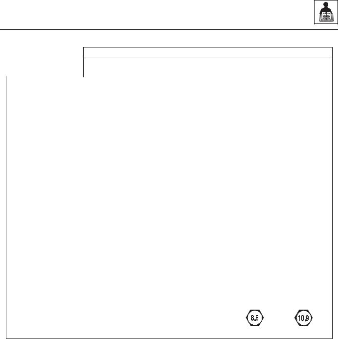
Note: These torque values do not apply to cadmium plated fasteners.
METRIC CLASS 8.8 METRIC CLASS 10.9
G5-18A/2505 |
2.5 |

General Information and Specifications
2.3SPECIFICATIONS
2.3.1 |
Travel Speed |
|
|
|
|
12 x 16.5 Tires (Standard) |
16 mph (26 kmph) |
|
|
|
|
14 x 17.5 Tires |
18 mph (29 kmph) |
|
|
|
|
2.3.2Hydraulic Cylinder Performance Specifications
Note: Machine with no load, engine at full throttle, hydraulic oil above 130° F (54° C) minimum, engine at operating temperature.
Function |
Approximate Times (sec.) |
|
|
Boom Extend |
6 |
|
|
Boom Retract |
4 |
|
|
Boom Lift |
6 |
|
|
Boom Lower |
4 |
|
|
Attachment Tilt - UP |
2 |
|
|
Attachment Tilt - DOWN |
2 |
|
|
2.3.3Electrical System
Note: Refer to Section 9.3, “Fuses and Relays,” for more information.
Battery:
Type, Rating |
12V DC, Negative (-) Ground, Limited Maintenance, |
|
Wet Charged |
|
|
Quantity |
1 (100 Ah) (C20) |
Reserve Capacity |
CCA @ -.4° F: 880 EN |
|
|
Group/Series |
DIN 600,44 |
|
|
Alternator |
12V, 75 Amps |
|
|
Starter |
12V, 3,0 KW Type EV (Gear Reduction) |
|
|
2.6 |
G5-18A/2505 |

|
|
General Information and Specifications |
|
|
|
|
|
|
|
|
|
2.3.4 |
Engine Performance Specifications |
|
|
|
|
|
|
|
Description |
|
|
|
|
||
Engine Make/Model |
Perkins 1104D-44T |
||
|
|
|
|
Low Idle |
|
900 ±50 rpm |
|
|
|
|
|
High Idle |
|
2150 ±50 rpm |
|
|
|
||
Horsepower |
84 BHP/ 64,5 kW @ 2200 rpm |
||
|
|
||
Fuel Delivery |
Fuel Injection |
||
|
|
||
Air Cleaner |
Dry Type, Replaceable Primary and Safety Elements |
||
|
|
||
Average Fuel Consumption (dependant on load/duty) |
1.6 gal/hr (6,1 I/hr) |
||
|
|
|
|
2.3.5Tires
Size |
Tire Type |
Minimum Ply/ |
Fill Type |
Pressure |
|
|
Star Rating |
|
|
|
|
|
|
|
12 x 16.5 |
NHS |
12 Ply |
Pneumatic |
80 psi (5,5 bar) |
|
|
|
|
|
|
|
|
Approx. 220 lb foam |
|
|
|
|
|
|
14 x 17.5 |
NHS |
12 Ply |
Pneumatic |
70 psi (4,8 bar) |
|
|
|
|
|
|
|
|
Approx. 220 lb foam |
|
|
|
|
|
|
Note: Standard wheel lug nut torque is 210-230 lb-ft (285 - 312 Nm). |
|
|
||
G5-18A/2505 |
2.7 |

General Information and Specifications
2.4FLUIDS, LUBRICANTS AND CAPACITIES
Engine Crankcase Oil
Capacity w/Filter Change |
9.6 quarts (9,0 liters) |
|
|
Filter Capacity |
1.05 quarts (1,0 liter) |
|
|
Oil Type |
15W-40 CE |
|
|
Fuel Tank |
|
|
|
Capacity |
24 gallons (90,8 liters) |
|
|
Type of Fuel |
U.S.A. #2 Diesel |
|
|
Cooling System |
|
|
|
System Capacity w/o Heater |
14.6 quarts (13,8 liters) |
|
|
Type of Fluid |
50/50 mix of ethylene glycol & water |
|
|
Axles |
|
|
|
Differential Housing Capacity - Front |
3.6 quarts (3,4 liters) |
|
|
Axle Drop Box - Front |
21 ounces (0,6 liters) |
|
|
Differential Housing Capacity - Rear |
3.6 quarts (3,4 liters) |
|
|
Wheel End Capacity |
10 ounces (0,3 liters) |
|
|
Type of Fluid |
Mobilfluid® 424 Tractor Hydraulic Fluid (ISO 46) |
Brakes |
|
|
|
Master Cylinder Capacity |
0.7 quarts (0,7 liters) |
|
|
Type of Fluid |
Mobilfluid® 424 Tractor Hydraulic Fluid (ISO 46) |
Hydraulic System |
|
|
|
System Capacity |
23.5 gallons (89 liters) |
|
|
Reservoir Capacity to FULL Mark |
16 gallons (60,6 liters) |
|
|
Type of Fluid |
Mobilfluid® 424 Tractor Hydraulic Fluid (ISO 46) |
Auxiliary Hydraulic Circuit Max Flow |
20 GPM (75,7 LPM) |
|
|
2.8 |
G5-18A/2505 |
General Information and Specifications
2.5 MAINTENANCE SCHEDULES |
2.5.2 |
1st 250, 250, 500 & 1000 Hour |
|
|
Maintenance Schedule |
|
|
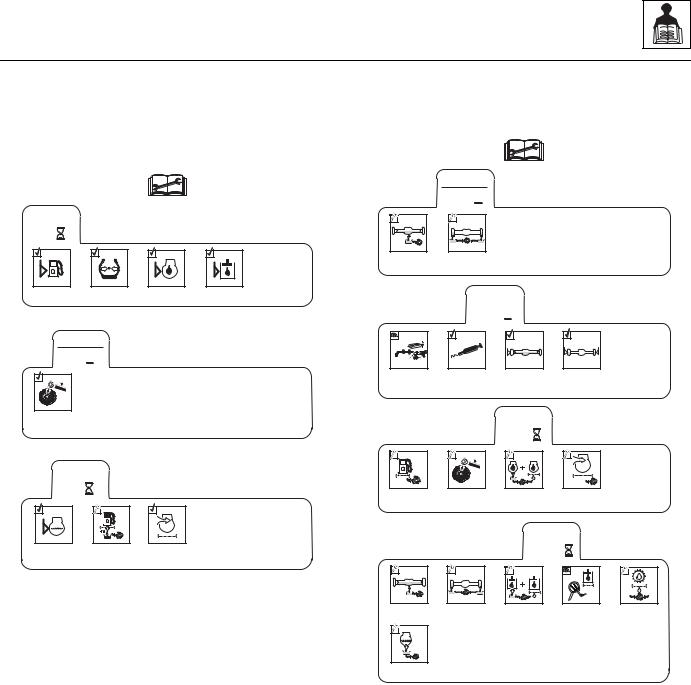
2.5.110,1st 50 & 50 Hour Maintenance Schedule
1st
250 
EVERY |
|
|
|
10 |
|
|
|
Check Fuel |
Check Tire |
Check Engine |
Check Hydraulic |
Level |
Pressure |
Oil Level |
Oil Level |
Change |
Axle Oil |
Change Wheel |
End Oil |
EVERY
250 
1st
50 
LB/FT |
(Nm) |
Check Wheel |
Lug Nut |
Torque |
EVERY |
|
|
50 |
|
|
Check Engine |
Drain Fuel/ |
Check |
Coolant Level |
Water |
Air Filter |
|
Separator |
|
Check Boom |
Bearing |
Pads |
Change Fuel |
Filter |
MY2560
Change
Axle Oil
Lubrication |
Check Axle |
Check Wheel |
Schedule |
Oil Level |
End Oil Levels |
LB/FT ( |
Nm) |
Check Wheel |
Lug Nut |
Torque |
EVERY |
|
500 |
|
Change Engine |
Change |
Oil and |
Air Filter |
Filter |
|
Change Wheel |
End Oil |
EVERY |
|
|
1000 |
|
|
Change |
Check |
Change |
Hydraulic |
Hydraulic Tank |
Transmission |
Fluid & Filters |
Cap |
Filter |
Change
Engine Coolant
MY2570
G5-18A/2505 |
2.9 |

General Information and Specifications
2.6LUBRICATION SCHEDULE
2.6.1250 Hour Lubrication Schedule
EVERY
250 
MYSTIK TETRIMOLY
(NLGI 2 GC-LB)
MY2580
2.10 |
G5-18A/2505 |
Section 3
Boom
Contents
PARAGRAPH |
TITLE |
PAGE |
|
3.1 |
Boom System Component Terminology . . . . . . . . . . . . . . . . . . . . . . . . . . . . . . . . |
3.2 |
|
3.2 |
Boom System - Two Section Boom . . . . . . . . . . . . . . . . . . . . . . . . . . . . . . . . . . . . |
3.3 |
|
|
3.2.1 |
Boom System Description. . . . . . . . . . . . . . . . . . . . . . . . . . . . . . . . . . . . . |
3.3 |
3.3 |
Boom Assembly Maintenance . . . . . . . . . . . . . . . . . . . . . . . . . . . . . . . . . . . . . . . . |
3.3 |
|
|
3.3.1 |
Second Section Boom Removal . . . . . . . . . . . . . . . . . . . . . . . . . . . . . . . . |
3.3 |
|
3.3.2 |
First Boom Section Removal. . . . . . . . . . . . . . . . . . . . . . . . . . . . . . . . . . . |
3.4 |
|
3.3.3 |
First Boom Section Installation . . . . . . . . . . . . . . . . . . . . . . . . . . . . . . . . . |
3.5 |
|
3.3.4 |
Second Boom Section Installation . . . . . . . . . . . . . . . . . . . . . . . . . . . . . . |
3.5 |
|
3.3.5 |
Complete Boom Removal . . . . . . . . . . . . . . . . . . . . . . . . . . . . . . . . . . . . . |
3.5 |
|
3.3.6 |
Second Section Boom Removal . . . . . . . . . . . . . . . . . . . . . . . . . . . . . . . . |
3.6 |
|
3.3.7 |
Second Section Boom Installation . . . . . . . . . . . . . . . . . . . . . . . . . . . . . . |
3.7 |
|
3.3.8 |
Boom Installation. . . . . . . . . . . . . . . . . . . . . . . . . . . . . . . . . . . . . . . . . . . . |
3.7 |
|
3.3.9 |
Extend/Retract Cylinder Removal . . . . . . . . . . . . . . . . . . . . . . . . . . . . . . . |
3.8 |
|
3.3.10 |
Extend/Retract Cylinder Installation . . . . . . . . . . . . . . . . . . . . . . . . . . . . . |
3.9 |
3.4 |
Boom Wear Pads. . . . . . . . . . . . . . . . . . . . . . . . . . . . . . . . . . . . . . . . . . . . . . . . . . . |
3.10 |
|
|
3.4.1 |
Wear Pad Inspection . . . . . . . . . . . . . . . . . . . . . . . . . . . . . . . . . . . . . . . . . |
3.10 |
|
3.4.2 |
Boom Wear Pad Replacement . . . . . . . . . . . . . . . . . . . . . . . . . . . . . . . . . |
3.10 |
|
3.4.3 |
Boom Wear Pad Lubrication . . . . . . . . . . . . . . . . . . . . . . . . . . . . . . . . . . . |
3.11 |
3.5 |
Quick Attach Assembly . . . . . . . . . . . . . . . . . . . . . . . . . . . . . . . . . . . . . . . . . . . . . |
3.11 |
|
|
3.5.1 |
Connecting with a Mechanical JLG Quick Attach . . . . . . . . . . . . . . . . . . . |
3.11 |
|
3.5.2 |
Connecting with a Hydraulic JLG Quick Attach. . . . . . . . . . . . . . . . . . . . . |
3.11 |
|
3.5.3 |
Connecting with a Universal Quick Attach . . . . . . . . . . . . . . . . . . . . . . . . |
3.12 |
|
3.5.4 |
Connecting a Hydraulic Operated Attachment . . . . . . . . . . . . . . . . . . . . . |
3.12 |
|
3.5.5 |
Quick Attach Removal. . . . . . . . . . . . . . . . . . . . . . . . . . . . . . . . . . . . . . . . |
3.13 |
|
3.5.6 |
Quick Attach Installation . . . . . . . . . . . . . . . . . . . . . . . . . . . . . . . . . . . . . . |
3.13 |
3.6 |
Troubleshooting . . . . . . . . . . . . . . . . . . . . . . . . . . . . . . . . . . . . . . . . . . . . . . . . . . . |
3.14 |
|
G5-18A/2505 |
3.1 |
Boom
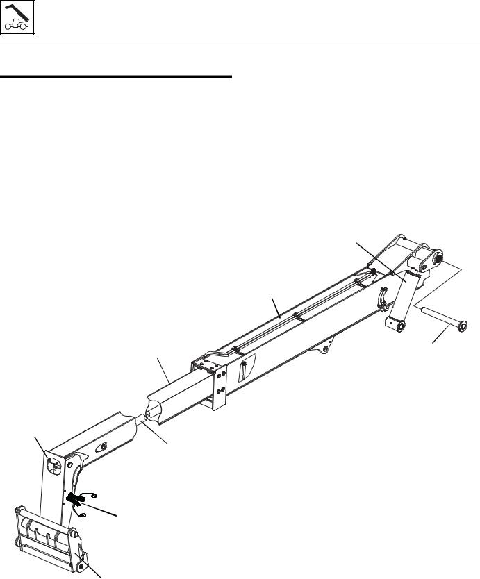
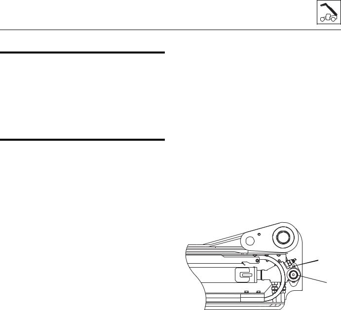
3.1BOOM SYSTEM COMPONENT TERMINOLOGY
To understand the safety, operation and maintenance information presented in this section, it is necessary that the operator/mechanic be familiar with the names and locations of the major assemblies of the boom system. The following illustration identifies the components that are referred to throughout this section.
COMPENSATING
CYLINDER
FIRST
BOOM
SECTION
SECOND |
|
|
BOOM |
PIVOT PIN |
|
SECTION |
||
|
TILT
CYLINDER
EXTEND/RETRACT
CYLINDER
AUXILIARY HYDRAULIC
QUICK CONNECTS
MY1940
QUICK
ATTACH
3.2 |
G5-18A/2505 |
Boom
3.2BOOM SYSTEM - TWO SECTION BOOM
3.2.1Boom System Description
The boom operates via an interchange among the electrical, hydraulic and mechanical systems. Components involved include the joystick, tilt cylinder, extend/retract cylinder, lift/lower cylinder, compensating cylinder, electronic sensors, various pivots, supporting hardware and other components.
3.3BOOM ASSEMBLY MAINTENANCE
The boom assembly consists of the first and second section booms and supporting hardware.
Note: Before removing the boom or boom section, the carriage or any other attachment must be removed from the quick attach.
Before beginning, conduct a visual inspection of the machine and work area, and review the task about to be undertaken. Read, understand and follow these instructions.
During service of the boom, perform the following:
1.Check wear pads. (Refer to Section 3.4.1, “Wear Pad Inspection.”)
2.Apply grease at all lubrication points (grease fittings). (Refer to Section 2.6, “Lubrication Schedule.”)
3.Check for proper operation by operating all boom functions through their full ranges of motion several times.
Depending on your particular circumstance, the following procedures explain the removal/installation of individual boom sections or removal/installation of the complete boom.
3.3.1Second Section Boom Removal
1.Remove any attachment from the quick switch assembly.
2.Be sure there is enough room in front of the machine to allow the boom sections to be removed. Park the machine on a hard, level surface, fully retract the boom, lower the boom, place the transmission control lever in (N) NEUTRAL, engage the park brake and shut the engine OFF.
3.Place an Do Not Operate Tag on both the ignition key switch and the steering wheel, stating that the machine should not be operated.
4.Remove the battery negative (-) cable from the battery negative (-) terminal.
5.Open the engine cover. Allow the system fluids to cool.
6.Remove the quick switch assembly. Refer to Section 3.5.5, “Quick Attach Removal.”
7.Label and disconnect the tilt hoses and (if equipped) auxiliary hydraulic hoses attached to the machine at the boom head. Plug and cap the hose ends to prevent dirt and debris from entering the hydraulic system.
8.Label and disconnect the extend/retract hydraulic tubes on the extend/retract cylinder at the rear of the boom.
9.Tag or identify each hose to the corresponding fitting it was removed from.
10.Remove the top and side wear pads from the rear of the second boom section.
Note: Tag each pad, backing plate, shim and bolts from each location.
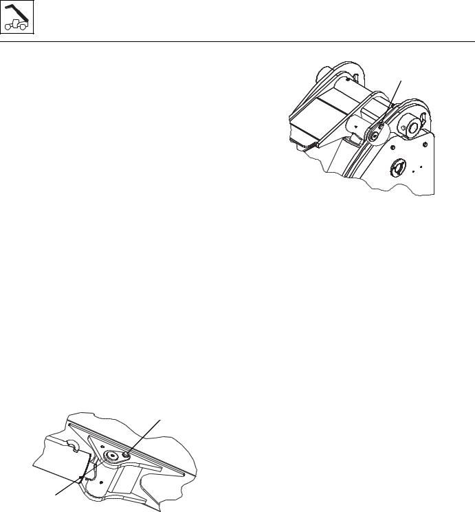
 1
1
 2
2
MY1960
11.Remove the lock bolt and nut (1) from the rear of the extend/retract cylinder.
12.Remove the extend/retract cylinder mounting pin (2).
13.Support the front of the boom by placing a sling behind the boom head. Pull the second boom section out of the first boom section approximately 6 in to 8 in (15 cm to 20 cm).
14.Pull the tilt hoses and (if equipped) auxiliary hydraulic hoses through the rear of the boom.
15.Remove the top, side and bottom wear pads from the front of the first boom section.
Note: Tag each pad, backing plate, shim and bolts from each location.
G5-18A/2505 |
3.3 |
Boom
16.Pull the second boom section halfway out of the first boom section, reposition the sling, balancing the second boom section and remove from the first boom section.
17.Set the second boom section on level ground. Set the complete boom on suitable stands to begin tear down.
18.Inspect the boom and welds. Consult your local JLG distributor if structural damage is detected.
19.Inspect hoses, hardware, wear pads, mounting points and other components visible with the first boom section. Replace any item if damaged.
20.Inspect all wear pads for wear. (Refer to Section 3.4.1, “Wear Pad Inspection.”)
3.3.2First Boom Section Removal
1.Temporarily install the battery negative (-) cable to the battery negative (-) terminal.
2.Start the machine and raise the first boom section to gain access to the lift cylinder pin and the comp cylinder pin.
Note: DO NOT activate ANY boom function other than the boom lift function. Activating the extend/retract, tilt or auxiliary function could cause hydraulic oil to spray onto the machine and/or surrounding areas.
3.Remove the battery negative (-) cable from the battery negative (-) terminal.
4.Support the first boom section by placing a sling at the balance point of the section.
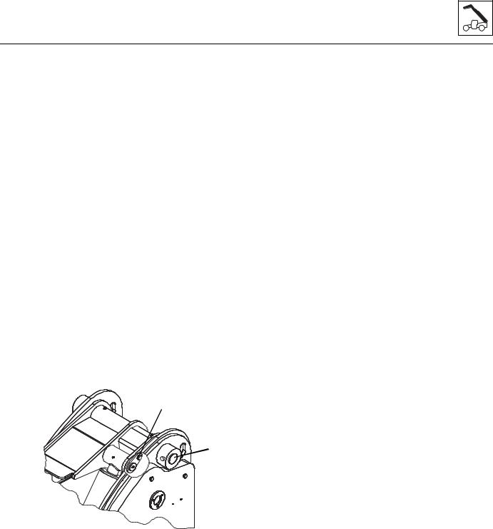
1
2 
MY1970
3
 4
4
MY1980
6.Remove the lock bolt and pin (3) from the rod end of the compensating cylinder on the first boom section. Rest the cylinder on the machine frame.
7.Remove the lock bolt and pivot pin (4) from rear of first boom section.
8.Lift the first boom section off machine and set on level ground or supports being careful not to damage the tubes on the bottom of the boom.
9.Inspect the boom and welds. Consult your local JLG distributor if structural damage is detected.
10.Inspect hoses, hardware, wear pads, mounting points and other components visible with the first boom section. Replace any item if damaged.
11.Inspect all wear pads for wear. (Refer to Section 3.4.1, “Wear Pad Inspection.”)
5.Support the lift/lower cylinder and remove the lock bolt (1) and then the rod end pin (2). Lower the lift/ lower cylinder onto the frame rails.
3.4 |
G5-18A/2505 |
Boom
3.3.3First Boom Section Installation
Note: Light lubrication of the boom wear surfaces with a factory authorized grease is recommended to keep the boom wear surfaces lubricated properly. Light lubrication of the boom wear surfaces is also recommended when the machine is stored, to help prevent rusting.
1.Park the machine on a hard, level surface, place the transmission control lever in (N) NEUTRAL, engage the park brake and shut the engine OFF.
2.Place an Do Not Operate Tag on both the ignition key switch and the steering wheel, stating that the machine should not be operated.
3.Open the engine cover. Allow the system fluids to cool.
Note: Grease the boom pivot bore, compensating cylinder rod ends, lift/lower cylinder rod end and pins before installing.
4.Using suitable slings, balance the first boom section, lift and carefully guide the boom into place. Align the frame pivot bore with the boom assembly pivot bore. Install boom pivot pin (5) and lock bolt. Apply Loctite® #242 and torque to 66 lb-ft (90 Nm).
5.With the sling still in place, install the compensating cylinder, pin (6) and lock bolt. Apply Loctite® #242 and torque to 66 lb-ft (90 Nm).
6
 5
5
MY1980
3.3.4Second Boom Section Installation
Note: Light lubrication of the boom wear surfaces with a factory authorized grease is recommended to keep the boom wear surfaces lubricated properly. Light lubrication of the boom wear surfaces is also recommended when the machine is stored, to help prevent rusting.
1.If previously removed, install the extend/retract cylinder into the rear of the second boom section. Pin and clip the barrel end of the cylinder in place.
2.Using suitable slings, balance the second boom section, lift and carefully guide the boom into place.
3.Install the wear pads, shims and bolts to their proper location at the front inside of the first boom section. DO NOT tighten the wear pads at this time.
4.Feed the tilt cylinder hoses and if equipped, the auxiliary hoses through the channel above the extend/retract cylinder.
5.Install the wear pads, shims and bolts previously removed from the rear of the second boom section. DO NOT tighten the wear pads at this time.
6.Uncap and reconnect the extend/retract cylinder fittings and plugs from extend/retract cylinder tubes. Attach each tube to the extend/retract cylinder fittings and tighten until wrench-tight. Mark the fitting, then tighten each tube firmly 1 to 1,5 flats.
7.Uncap and reconnect the tilt hoses and (if equipped) auxiliary hoses. Attach both sets to their appropriate fittings until wrench-tight. Mark the fitting, then tighten each hose firmly 1 to 1,5 flats.
8.Adjust and shim each wear pad as needed.
9.Start the engine and operate all boom functions several times to bleed any air out of the hydraulic system. Check for fluid leaks. Check the hydraulic fluid level in the tank and add fluid as required.
10.Clean up all debris, hydraulic fluid, etc., in, on, near and around the machine.
11.Close and secure the engine cover.
6.With the sling still in place, install the rod end of the lift/lower cylinder, pin and lock bolt. Apply Loctite® #242 and torque to 66 lb-ft (90 Nm).
Note: Raising the boom up or down with the sling may be necessary so the boom, compensating and lift/lower cylinder bores can be aligned for easier pin installation.
7. Make sure boom section is level, then remove sling.
3.3.5Complete Boom Removal
1.Remove any attachment from the quick switch assembly.
2.Be sure there is enough room in front of the machine to allow the boom sections to be removed. Park the machine on a hard, level surface, fully retract the boom, Raise the boom to allow access to the lift cylinder and the comp cylinder pivot pins, place the transmission control lever in (N) NEUTRAL, engage the park brake and shut the engine OFF.
G5-18A/2505 |
3.5 |
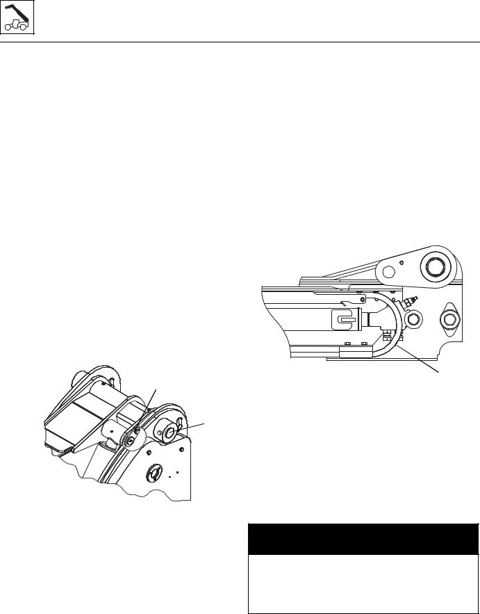
Boom
3.Place an Do Not Operate Tag on both the ignition key switch and the steering wheel, stating that the machine should not be operated.
4.Remove the battery negative (-) cable from the battery negative (-) terminal.
5.Open the engine cover. Allow the system fluids to cool.
6.Remove the quick switch assembly. Refer to Section 3.5.5, “Quick Attach Removal.”
7.Support the boom by placing a sling around the boom head. Support the lift/lower cylinder and remove the lock bolt and then the rod end pin. Lower the lift/lower cylinder onto the frame rails.
8.Label and disconnect the tilt and auxiliary hydraulic hoses attached to the machine at the tubes on top of the boom. Plug and cap the hose ends to prevent dirt and debris from entering the hydraulic system.
9.Label and disconnect the extend/retract hydraulic hoses at the tubes on the side of the boom.
Note: Tag or identify each hose to the corresponding fitting it was removed from.
10.Remove the lock bolt and pin (1) from the rod end of the compensating cylinder on the first boom section. Rest the cylinder on the machine frame.
3.3.6Second Section Boom Removal
1.At the boom head, attach a sling around the tilt cylinder. Remove both hoses from tilt cylinder. Plug the hose ends and cap the tilt cylinder fittings to prevent dirt and debris from entering the hydraulic system. Remove the clip from barrel end of tilt cylinder pin. Remove the tilt cylinder pin and lower the tilt cylinder out of the boomhead.
2.Remove the extend /retract tubes from the extend / retract cylinder from the rear of the boom.
3.If equipped, unscrew the auxiliary hoses. Plug the hose ends to prevent dirt and debris from entering the hydraulic system.
Note: Tag or identify each hose to the corresponding fitting it was removed from.
MY1990
1
2
MY1980
11.Lower the boom to a level position and place a suitable support under the rear of the boom. Reposition the slings to each end of the boom.
12.Remove the lock bolt and pivot pin (2) from rear of first boom section.
13.Lift the complete boom off machine and set on level ground or supports being careful not to damage the tubes on the bottom of the boom.
 3
3
4.Remove the lock nut, bolt and pin from rod end of the extend/retract cylinder.
5.Pull the second boom section out 6 in to 8 in
(15 cm to 20 cm) to be able to loosen and remove all the bolts and remove all the wear pads, backing plates and shims from the rear outside of the second section boom and the front inside of the first section boom. Tag each pad, backing plate, shim and bolts from each location.
6.Carefully pull the tilt and auxiliary hydraulic hoses (3) through the rear of the first boom section.
 WARNING
NEVER weld or drill the boom unless approved in writing by JLG. The structural integrity of the boom will be impaired if subjected to any repair involving welding or drilling. Failure to comply could result in death or severe personal injury.
7. Pull out the remainder of the second boom section.
3.6 |
G5-18A/2505 |
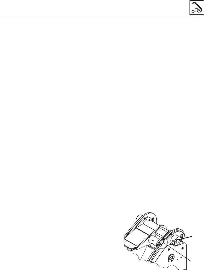
Boom
8.Inspect the boom and welds. Consult your local JLG distributor if structural damage is detected.
9.Inspect hoses, hardware, wear pads, mounting points and other components visible with the first boom section. Replace any item if damaged.
10.Inspect all wear pads for wear. (Refer to Section 3.4.1, “Wear Pad Inspection.”)
3.3.7Second Section Boom Installation
1.If previously removed, insert the extend/retract cylinder through the rear of the second boom section and attach the pin and clip to the barrel end.
2.Install the bottom rear wear pads, washers and bolts into the second boom section. Apply Loctite® #242 and torque to 66 lb-ft (90 Nm).
Note: Apply Loctite® #242 to all wear pad bolts prior to installing wear pads.
3.Grease the inside of the first boom section on areas where the second boom section wear pads will slide.
4.Using a suitable sling, carefully slide the second boom section 3 ft to 4 ft (1 m to 1.5 m) into the front of the first boom section. Set the second boom section head onto suitable supports and reset sling under the boom head of the second section. Carefully slide the second section into the first section. Leave 6 in to 8 in (15 cm to 20 cm) of the second section out to be able to install wear pads in front of the first boom section.
5.With the sling still under the boom head, install the top wear pads, washers and bolts in the front of the first boom section. Apply Loctite ® #242 and torque to 66 lb-ft (90 Nm). Raise the second boom section and install the bottom wear pads, backing plates, shims and bolts in the front of the first boom section Apply Loctite ® #242 and torque to 66 lb-ft (90 Nm). Install the left and right side front wear pads, backing plates, shims and bolts in the front of the first boom section. Apply Loctite® #242 and torque to 66 lb-ft (90 Nm).
6.Install the top rear left and right side wear pads, backing plate and bolts (do not shim or tighten bolts). Install the left and right side rear wear pads, backing plates and bolts, do not shim or tighten bolts).
Note: Light lubrication of the boom wear surfaces with a factory authorized grease is recommended to keep the boom wear surfaces lubricated properly.
7.Tighten all rear wear pad bolts after ensuring the minimum gap requirements have been met. Refer to Section 3.4.1, “Wear Pad Inspection.”
G5-18A/2505
8.Slide the tilt and auxiliary hoses between the boom sections.
9.Insert the pin and secure the rod end of the extend/ retract cylinder in place with the bolt and locknut.
10.Install both tubes to the rear of the extend/retract cylinder.
11.Lift the tilt cylinder into place and insert the pins and clips to secure the cylinder to the boomhead.
12.Uncap and reconnect the tilt and auxiliary hoses and attach to their appropriate locations.
3.3.8Boom Installation
Note: Light lubrication of the boom wear surfaces with a factory authorized grease is recommended to keep the boom wear surfaces lubricated properly. Light lubrication of the boom wear surfaces is also recommended when the machine is stored, to help prevent rusting.
1.Park the machine on a hard, level surface, place the transmission control lever in (N) NEUTRAL, engage the park brake and shut the engine OFF.
2.Place an Do Not Operate Tag on both the ignition key switch and the steering wheel, stating that the machine should not be operated.
3.Open the engine cover. Allow the system fluids to cool.
Note: Grease the boom pivot bore, compensating cylinder rod ends, lift/lower cylinder rod end and pins before installing.
4.Using suitable slings, balance the boom assembly, lift and carefully guide the boom into place. Align the frame pivot bore with the boom assembly pivot bore. Install boom pivot pin (4) and lock bolt. Apply Loctite® #242 and torque to 66 lb-ft (90 Nm).
5.With the sling still in place, install the compensating cylinder, pin (5) and lock bolt. Apply Loctite® #242 and torque to 66 lb-ft (90 Nm).
 4
4
5
MY1980
3.7
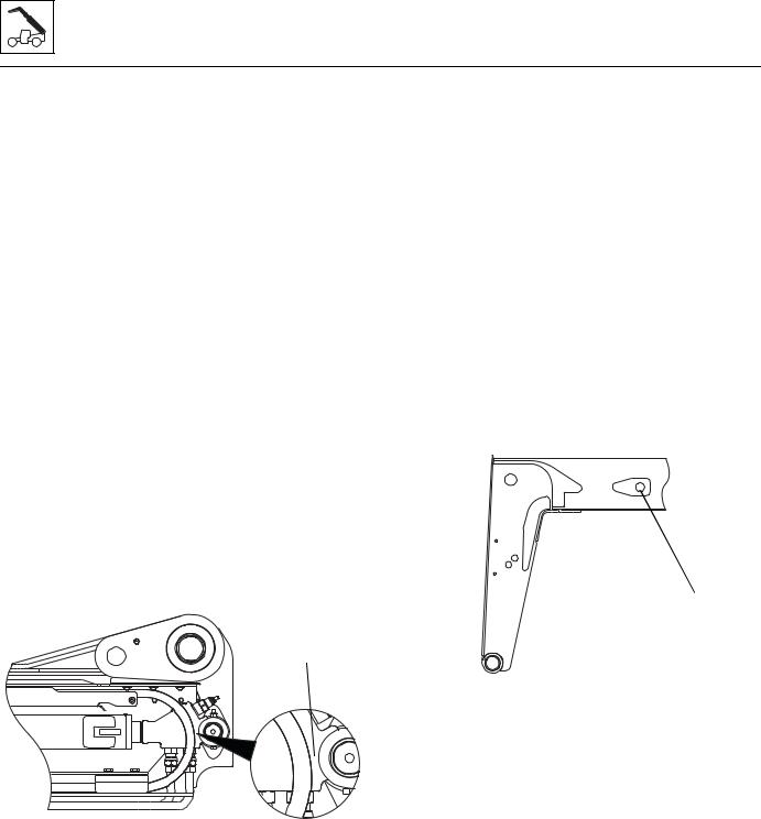
Boom
6.With the sling still in place, install the rod end of the lift/lower cylinder, pin and lock bolt. Apply Loctite® #242 and torque to 66 lb-ft (90 Nm).
Note: Raising the boom up or down with the sling may be necessary so the boom, compensating and lift/lower cylinder bores can be aligned for easier pin installation.
7.Uncap and reconnect the extend/retract cylinder fittings and plugs from extend/retract cylinder tubes. Attach each tube to the extend/retract cylinder fittings and tighten until wrench-tight. Mark the fitting, then tighten each tube firmly 1 to 1,5 flats.
8.Uncap and reconnect the tilt hoses and (if equipped) auxiliary hoses. Attach both sets to their appropriate fittings until wrench-tight. Mark the fitting, then tighten each hose firmly 1 to 1,5 flats.
9.Start the engine and operate all boom functions several times to bleed any air out of the hydraulic system. Check for fluid leaks. Check the hydraulic fluid level in the tank and add fluid as required.
10.Check clearance (1) between the tilt hoses (and if equipped) auxiliary hoses and the front of the extend/retract cylinder trunnion. There should be approximately 1/2 in. (12,7 mm) of clearance.
11.If adjustment is needed, loosen the tilt tubes (and if equipped) auxiliary tubes. Move tubes to achieve the proper clearance.
3.3.9Extend/Retract Cylinder Removal
1.Remove any attachment from the quick attach assembly. Refer to Section 3.5, “Quick Attach Assembly.”
2.Park the machine on a hard, level surface, extend the boom to gain access to the extend/retract cylinder pin in the second boom section (approximately 3 ft (1 m), level the boom assembly, place the transmission control lever in (N) NEUTRAL, engage the park brake and shut the engine OFF.
Note: The boom must be properly aligned (level) with the access hole at the rear of the frame to allow removal of the extend/retract cylinder barrel mounting pin.
3.Place a Do Not Operate Tag on both the ignition key switch and the steering wheel, stating that the machine should not be operated.
4.Open the engine cover. Allow the system fluids to cool.
1
MY2000
12.Clean up all debris, hydraulic fluid, etc., in, on, near and around the machine.
13.Close and secure the engine cover.
2
MY2680
5.Remove the battery negative (-) cable from the battery negative (-) terminal.
6.Remove the cylinder rod eye retaining clips and mounting pin (2) at the side of the second boom section.
7.Loosen and remove the hose clamps and cover plate (3) from the rear of the boom assembly.
8.Label and disconnect the tilt and auxiliary hydraulic hoses attached to the machine at the tubes on top of the boom (4). Plug and cap the hose ends to prevent dirt and debris from entering the hydraulic system.
9.Loosen and remove the extend/retract cylinder tubes at the rear of the first boom section. Plug the tube ends to prevent dirt and debris from entering the hydraulic system.
3.8 |
G5-18A/2505 |
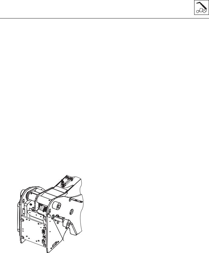
Boom
10.Loosen and remove both fittings from the bottom of the extend/retract cylinder barrel. Plug the openings in the extend/retract cylinder barrel.
11.Loosen and remove the locking bolt on the cylinder barrel mounting pin.
12.Remove the cylinder barrel pin (5). Note the location of the spacers and washers.
13.Attach a sling or other suitable lifting device to the extend/retract cylinder and carefully pull the extend/ retract cylinder free of the machine through the rear of the boom/chassis assembly.
Note: The tilt hoses and if equipped, the auxiliary hoses may need to be moved during removal of the extend/ retract cylinder.
14.Place the extend/retract cylinder in a designated area for the next operation.
3.3.10Extend/Retract Cylinder Installation
1.Carefully install the extend/retract cylinder into the rear of the boom and line up the barrel end of the cylinder with the pin bores on the first boom section.
Note: The tilt hoses and if equipped, the auxiliary hoses may need to be moved during installation of the extend/ retract cylinder.
2.Install the mounting pin (5), spacers and washers through the frame access hole on the chassis and the first boom section bore and cylinder barrel.
Secure with retaining clips.
4 


3
5
MY2670
3.Remove the plugs in the bottom of the extend/retract cylinder and install the previously removed fittings.
4.Uncap and connect the tubes to the previously labeled fittings at the extend/retract cylinder. Apply Loctite 545® to the fittings.
G5-18A/2505
5.Uncap and reconnect the tilt hoses and (if equipped) auxiliary hoses (4). Attach both sets to their appropriate fittings until wrench-tight. Mark the fitting, then tighten each hose firmly 1 to 1,5 flats.
6.Install the cover plate and hose clamps (3) at the rear of the boom assembly.
7.Install the battery negative (-) cable to the battery negative (-) terminal.
8.Start the machine and extend the extend/retract cylinder until the rod eye of the cylinder aligns with the pin bore in the second boom section.
9.Shut the engine OFF.
10.Install the mounting pin through the side of the second boom section (2) and secure with the retaining clips.
11.Start the machine and cycle the extend/retract cylinder checking for leaks or any alignment problems.
3.9
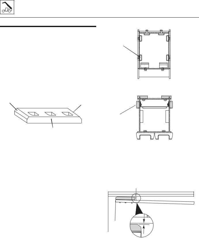
Boom
3.4BOOM WEAR PADS
On the G5-18A a total of 14 wear pads are installed on the boom.
Twelve of the fourteen wear pads on this boom are flat rectangular wear pads with metal inserts. Two wear pads on the bottom of the second section boom are channeled for tilt hose and auxiliary hose clearance.
3.4.1Wear Pad Inspection
Inspect all wear pads (2) for wear. If the angle indicators (3) on the ends of the wear pads are visible, the wear pads can be reused. If the pads show uneven wear (front to back), they should be replaced. Replace pads as a set if worn or damaged.
3 |
3 |
|
2 |
MA2070 |
3.4.2Boom Wear Pad Replacement
When replacing a wear pad on the boom, replace both wear pads on that side of the boom; e.g.: replace top front left and top front right wear pads at the same time.
Usually, shimming will remain the same when installing new wear pads. All wear pads are secured to the boom using different capscrews and washers. When installing new wear pads, apply Loctite® #242 to all wear pad mounting capscrews M10 x 1,5 and torque to 23 lb-ft (31Nm). On 5/16 x 18 capscrews, apply Loctite® #242 to and torque to 17 lb-ft (23 Nm). Grease the new pads and surrounding area.
The boom wear pads are mounted on the inside of the first boom section (4) and the outside of the second boom section (5).
3.10
4
MY2010
5
MY2020
Use shims under the wear pads as required to maintain a maximum gap of 0.06 in (1,5 mm) (6) between the wear pad on the front and sides of the boom. The gap at the rear of the boom should be no more than 0.12 in (3 mm).
Shims are available in four thicknesses, 0.02 in (0,5mm), 0.04 in (1 mm), 0.06 in (1,5mm) and 0.08 in (2,0mm).
6 |
MU4080 |
G5-18A/2505
Loading...