


ANSI
®
Operation and Safety Manual
Original Instructions - Keep this manual with the machine at all times.
Model(s)
X550AJ
P/N - 3128791
September 26, 2011

NOTES:

SECTION - FOREWORD
FOREWORD
This manual is a very important tool! Keep it with the machine at all times.
The purpose of this manual is to provide owners, users, operators, lessors, and lessees with the precautions and
operating procedures essential for the safe and proper machine operation for its intended purpose.
Due to continuous product improvements, JLG Industries, Inc. reserves the right to make specification changes
without prior notification. Contact JLG Industries, Inc. for updated information.
3128791 – JLG Lift – a

SECTION - SAFETY ALERT SYMBOLS AND SAFETY SIGNAL WORDS
SAFETY ALERT SYMBOLS AND SAFETY SIGNAL WORDS
This is the Safety Alert Symbol. It is used to alert you to the potential personal injury hazards. Obey all safety messages
that follow this symbol to avoid possible injury or death.
INDICATES AN IMMINENTLY HAZARDOUS SITUATION. IF NOT
AVOIDED, WILL
DECAL WILL HAVE A RED BACKGROUND.
INDICATES A POTENTIALITY HAZARDOUS SITUATION. IF NOT
AVOIDED, COULD RESULT IN SERIOUS INJURY OR DEATH. THIS
DECAL WILL HAVE AN ORANGE BACKGROUND.
RESULT IN SERIOUS INJURY OR DEATH. THIS
INDICATES A POTENTIALITY HAZARDOUS SITUATION. IF NOT
AVOIDED, MAY
ALSO ALERT AGAINST UNSAFE PRACTICES. THIS DECAL WILL
HAVE A YELLOW BACKGROUND.
INDICATES INFORMATION OR A COMPANY POLICY THAT RELATES
DIRECTLY OR INDIRECTLY TO THE SAFETY OF PERSONNEL OR
PROTECTION OF PROPERTY.
RESULT IN MINOR OR MODERATE INJURY. IT MAY
b – JLG Lift – 3128791

SECTION - SAFETY ALERT SYMBOLS AND SAFETY SIGNAL WORDS
THIS PRODUCT MUST COMPLY WITH ALL SAFETY RELATED BULLETINS. CONTACT JLG INDUSTRIES, INC. OR THE LOCAL AUTHORIZED JLG REPRESENTATIVE FOR INFORMATION REGARDING
SAFETY RELATED BULLETINS WHICH MAY HAVE BEEN ISSUED
FOR THIS PRODUCT.
For :
• Accident Reporting
• Product Safety Publications
• Current Owner Updates
• Questions Regarding
Product Safety
• Standards and Regulations
Compliance Information
• Questions Regarding Special Product Applications
• Questions Regarding Product Modifications
JLG INDUSTRIES, INC. SENDS SAFETY RELATED BULLETINS TO
THE OWNER OF RECORD OF THIS MACHINE. CONTACT JLG
INDUSTRIES, INC. TO ENSURE THAT THE CURRENT OWNER
RECORDS ARE UPDATED AND ACCURATE.
JLG INDUSTRIES, INC. MUST BE NOTIFIED IMMEDIATELY IN ALL
INSTANCES WHERE JLG PRODUCTS HAVE BEEN INVOLVED IN AN
ACCIDENT INVOLVING BODILY INJURY OR DEATH OF PERSONNEL
OR WHEN SUBSTANTIAL DAMAGE HAS OCCURRED TO PERSONAL
PROPERTY OR THE JLG PRODUCT.
Contact :
Product Safety and Reliability Department
JLG Industries, Inc.
13224 Fountainhead Plaza
Hagerstown, MD 21742
USA
or Your Local JLG Office
(See addresses on inside of manual cover)
In USA:
Toll Free: 877-JLG-SAFE (877-554-7233)
Outside USA:
3128791 – JLG Lift – c
Phone: 240-420-2661
E-mail: ProductSafety@JLG.com

SECTION - REVISION LOG
Original Issue of Manual . . . . . . . . . . . . . . . . . July 22, 2011
Manual Revised . . . . . . . . . . . . . . . . . . September 26, 2011
REVISION LOG
d – JLG Lift – 3128791

TABLE OF CONTENTS
SECTION - PARAGRAPH, SUBJECT PAGE SECTION - PARAGRAPH, SUBJECT PAGE
FOREWORD. . . . . . . . . . . . . . . . . . . . . . . . . . . . . . . . A
SAFETY ALERT SYMBOLS AND SAFETY SIGNAL
WORDS . . . . . . . . . . . . . . . . . . . . . . . . . . . . . . . . . . . B
Contact : . . . . . . . . . . . . . . . . . . . . . . . . . . . . . . . . . C
In USA: . . . . . . . . . . . . . . . . . . . . . . . . . . . . . . . . . . C
Outside USA: . . . . . . . . . . . . . . . . . . . . . . . . . . . . . C
REVISION LOG . . . . . . . . . . . . . . . . . . . . . . . . . . . . . D
SECTION - 1 - SAFETY PRECAUTIONS
1.1 GENERAL. . . . . . . . . . . . . . . . . . . . . . . . . . . . . . . . . 1-1
Operator Training and Knowledge . . . . . . . . . . . . 1-1
1.2 BEFORE OPERATING THE LIFT . . . . . . . . . . . . . . . 1-2
Workplace Inspection . . . . . . . . . . . . . . . . . . . . . . 1-2
Machine Inspection. . . . . . . . . . . . . . . . . . . . . . . . 1-3
1.3 OPERATION. . . . . . . . . . . . . . . . . . . . . . . . . . . . . . . 1-3
General . . . . . . . . . . . . . . . . . . . . . . . . . . . . . . . . . 1-3
Trip and Fall Hazards . . . . . . . . . . . . . . . . . . . . . . 1-4
Electrocution Hazards . . . . . . . . . . . . . . . . . . . . . 1-5
Tipping Hazards . . . . . . . . . . . . . . . . . . . . . . . . . . 1-6
Crushing and Collision Hazards. . . . . . . . . . . . . . 1-8
1.4 LIFTING, AND HAULING . . . . . . . . . . . . . . . . . . . . . 1-9
1.5 ADDITIONAL HAZARDS / SAFETY . . . . . . . . . . . . . 1-9
SECTION - 2 - PREPARATION AND INSPECTION
2.1 PERSONNEL TRAINING . . . . . . . . . . . . . . . . . . . . . 2-1
Operator Training . . . . . . . . . . . . . . . . . . . . . . . . . 2-1
Training Supervision . . . . . . . . . . . . . . . . . . . . . . . 2-1
Operator Responsibility . . . . . . . . . . . . . . . . . . . . 2-1
2.2 PREPARATION, INSPECTION, AND
MAINTENANCE. . . . . . . . . . . . . . . . . . . . . . . . . . . . 2-2
Pre-Start Inspection . . . . . . . . . . . . . . . . . . . . . . . 2-4
Function Check . . . . . . . . . . . . . . . . . . . . . . . . . . 2-5
General. . . . . . . . . . . . . . . . . . . . . . . . . . . . . . . . . 2-9
SECTION - 3 - MACHINE CONTROLS, INDICATORS AND
OPERATION
3.1 GROUND CONTROL STATION . . . . . . . . . . . . . . . 3-1
3.2 PLATFORM/REMOTE CONTROL STATION. . . . . . 3-4
Control Position On The Ground: . . . . . . . . . . . . 3-4
Control Position From In The Platform: . . . . . . . . 3-5
Platform/Remote Control Station Functions . . . . 3-6
Platform/Remote Control Station LCD Display . 3-10
SECTION - 4 - MACHINE OPERATION
4.1 DESCRIPTION. . . . . . . . . . . . . . . . . . . . . . . . . . . . . 4-1
4.2 BOOM OPERATING CHARACTERISTICS AND
LIMITATIONS. . . . . . . . . . . . . . . . . . . . . . . . . . . . . . 4-1
Capacities. . . . . . . . . . . . . . . . . . . . . . . . . . . . . . . 4-1
Stability . . . . . . . . . . . . . . . . . . . . . . . . . . . . . . . . . 4-1
4.3 ENGINE OPERATION . . . . . . . . . . . . . . . . . . . . . . . 4-2
Gas/Diesel Starting Procedure . . . . . . . . . . . . . . 4-2
Gas/Diesel Engine Shutdown Procedure . . . . . . 4-3
Electric Engine Starting Procedure -
AC Voltage Machine. . . . . . . . . . . . . . . . . . . . . . . 4-3
3128791 – JLG Lift – i

TABLE OF CONTENTS
SECTION - PARAGRAPH, SUBJECT PAGE SECTION - PARAGRAPH, SUBJECT PAGE
Electric Engine Starting Procedure -
LITHIUM-ION Machine . . . . . . . . . . . . . . . . . . . . . 4-4
4.4 BASE AND BOOM/JIB ALIGNMENT . . . . . . . . . . . .4-5
4.5 TRACKS - DRIVING, STEERING AND
TRACK WIDTH ADJUST . . . . . . . . . . . . . . . . . . . . .4-6
Track width adjust. . . . . . . . . . . . . . . . . . . . . . . . . 4-6
Travelling (Drive and Steer) . . . . . . . . . . . . . . . . .4-6
Travelling (Grades and Side Slopes) . . . . . . . . . . 4-7
Jib Position for Travelling . . . . . . . . . . . . . . . . . . . 4-9
4.6 OUTRIGGER OPERATION. . . . . . . . . . . . . . . . . . . 4-10
Setting Outriggers From the Platform/
Remote Console . . . . . . . . . . . . . . . . . . . . . . . . .4-12
Retracting The Outriggers . . . . . . . . . . . . . . . . . 4-13
4.7 BOOM/PLATFORM OPERATION. . . . . . . . . . . . . . 4-14
Overload Alarm . . . . . . . . . . . . . . . . . . . . . . . . . .4-14
Platform Level Adjustment . . . . . . . . . . . . . . . . .4-14
Raise And Lower The Tower Boom . . . . . . . . . .4-16
Raise And Lower The Main Boom . . . . . . . . . . .4-16
Telescope The Main Boom. . . . . . . . . . . . . . . . . 4-16
Platform Rotation . . . . . . . . . . . . . . . . . . . . . . . . 4-16
Raise And Lower The Jib . . . . . . . . . . . . . . . . . . 4-16
Emergency Lowering . . . . . . . . . . . . . . . . . . . . . 4-18
Platform Removal/Installation . . . . . . . . . . . . . . .4-18
4.8 BATTERY CHARGING -
GAS/DIESEL/AC-ELECTRIC . . . . . . . . . . . . . . . . . 4-19
Battery Charging - Daily . . . . . . . . . . . . . . . . . . . 4-19
4.9 BATTERY CHARGING - LITHIUM-ION MACHINE .4-20
Charging the Battery Pack . . . . . . . . . . . . . . . . . 4-20
Charge Curve . . . . . . . . . . . . . . . . . . . . . . . . . . . 4-22
4.10 SHUT DOWN AND PARK . . . . . . . . . . . . . . . . . . . 4-22
4.11 LIFTING AND TIE DOWN . . . . . . . . . . . . . . . . . . . 4-24
Lifting . . . . . . . . . . . . . . . . . . . . . . . . . . . . . . . . . 4-24
Tie Down. . . . . . . . . . . . . . . . . . . . . . . . . . . . . . . 4-25
4.12 MACHINE DECALS . . . . . . . . . . . . . . . . . . . . . . . . 4-27
SECTION - 5 - EMERGENCY PROCEDURES
5.1 GENERAL . . . . . . . . . . . . . . . . . . . . . . . . . . . . . . . . 5-1
5.2 INCIDENT NOTIFICATION . . . . . . . . . . . . . . . . . . . 5-1
5.3 EMERGENCY OPERATION . . . . . . . . . . . . . . . . . . 5-1
Power Main Cut-Off Switch Location . . . . . . . . . . 5-1
Operator Unable to Control Machine. . . . . . . . . . 5-2
Platform or Boom Caught Overhead . . . . . . . . . . 5-2
Manual Descent with Engine Running and
Electrical Power . . . . . . . . . . . . . . . . . . . . . . . . . . 5-2
Manual Descent with Engine Running but without
Electrical Power (Combustion Engines Only) . . . 5-6
Manual Descent without Engine and
Electrical Power . . . . . . . . . . . . . . . . . . . . . . . . . . 5-7
Outrigger/Track Movement
Emergency Procedure . . . . . . . . . . . . . . . . . . . . . 5-9
5.4 SAFETY DEVICES BYPASS KEY USE . . . . . . . . . 5-13
Using The Emergency Descent In The Case Of
An Outrigger Losing Contact With The Ground. 5-14
Machine Realignment Emergency Procedure. . 5-15
ii – JLG Lift – 3128791

TABLE OF CONTENTS
SECTION - PARAGRAPH, SUBJECT PAGE SECTION - PARAGRAPH, SUBJECT PAGE
5.5 LITHIUM-ION BATTERY PACK -
HANDLING IN DANGEROUS CONDITIONS . . . . . 5-16
Procedure For Handling Hot Cells . . . . . . . . . . . 5-16
Procedure For Handling Vented Cells . . . . . . . . 5-17
Procedure For Exploded Cells . . . . . . . . . . . . . . 5-19
Lithium Battery Fire . . . . . . . . . . . . . . . . . . . . . . . 5-20
SECTION - 6 - GENERAL SPECIFICATIONS AND
OPERATOR MAINTENANCE
6.1 INTRODUCTION . . . . . . . . . . . . . . . . . . . . . . . . . . .6-1
6.2 OPERATING SPECIFICATIONS . . . . . . . . . . . . . . .6-2
Dimensional Data . . . . . . . . . . . . . . . . . . . . . . . . . 6-2
Chassis . . . . . . . . . . . . . . . . . . . . . . . . . . . . . . . . . 6-2
Capacities . . . . . . . . . . . . . . . . . . . . . . . . . . . . . . . 6-3
Engine Data . . . . . . . . . . . . . . . . . . . . . . . . . . . . . 6-3
Lithium-Ion Specifications. . . . . . . . . . . . . . . . . . . 6-4
Machine Major Component Weights . . . . . . . . . . 6-4
6.3 SERVICE/MAINTENANCE . . . . . . . . . . . . . . . . . . . . 6-5
Lubrication . . . . . . . . . . . . . . . . . . . . . . . . . . . . . .6-6
Rubber Track Maintenance/Replacement . . . . . 6-13
Wear Pad Inspection. . . . . . . . . . . . . . . . . . . . . . 6-16
Turntable Attach Bolts . . . . . . . . . . . . . . . . . . . . 6-16
Battery Maintenance and Charging -
Gas/Diesel/AC-Electric . . . . . . . . . . . . . . . . . . . . 6-16
6.4 ELECTRIC MOTOR MAINTENANCE . . . . . . . . . . . 6-17
Electric Motor . . . . . . . . . . . . . . . . . . . . . . . . . . . 6-17
6.5 PLATFORM/REMOTE CONTROL
SERVICE MENU . . . . . . . . . . . . . . . . . . . . . . . . . . 6-17
Service Button . . . . . . . . . . . . . . . . . . . . . . . . . . 6-17
Menu Input . . . . . . . . . . . . . . . . . . . . . . . . . . . . . 6-18
Errors Menu . . . . . . . . . . . . . . . . . . . . . . . . . . . . 6-20
Working Hours Menu . . . . . . . . . . . . . . . . . . . . . 6-20
Set-up Menu. . . . . . . . . . . . . . . . . . . . . . . . . . . . 6-20
Joystick Menu . . . . . . . . . . . . . . . . . . . . . . . . . . 6-20
6.6 LITHIUM-ION MACHINE - MAINTAINANCE . . . . . 6-21
Cleaning the Machine . . . . . . . . . . . . . . . . . . . . 6-21
Battery Pack System Components and
Maintenance. . . . . . . . . . . . . . . . . . . . . . . . . . . . 6-22
Lithium-Ion Machine Fault Codes . . . . . . . . . . . 6-24
BMS Fault Codes -
(Battery Management System) . . . . . . . . . . . . . 6-27
Battery Charger Fault Codes . . . . . . . . . . . . . . . 6-28
SECTION - 7 - INSPECTION AND REPAIR LOG
3128791 – JLG Lift – iii

TABLE OF CONTENTS
SECTION - PARAGRAPH, SUBJECT PAGE SECTION - PARAGRAPH, SUBJECT PAGE
LIST OF FIGURES
2-1. Basic Machine Nomenclature . . . . . . . . . . . . . .2-6
2-2. Daily Walk-Around Inspection . . . . . . . . . . . . . .2-8
3-1. Swing Control Valve . . . . . . . . . . . . . . . . . . . . . .3-2
3-2. Ground Control Station . . . . . . . . . . . . . . . . . . .3-3
3-3. Platform/Remote Control Station . . . . . . . . . . . .3-9
4-1. Ground/Emergency Control Box . . . . . . . . . . . . 4-2
4-2. Grade and Side Slope Definition . . . . . . . . . . . .4-8
4-3. Platform/Remote Control Box. . . . . . . . . . . . . . 4-15
4-4. Platform - Load/Reach Chart . . . . . . . . . . . . . . 4-17
4-5. Lifting Machine - Attach Points . . . . . . . . . . . . . 4-24
4-6. Machine Tie-Down Points. . . . . . . . . . . . . . . . .4-26
4-7. Decal installation - Standard - Right Side . . . .4-27
4-8. Decal Installation - Standard - Left Side. . . . . . 4-28
4-9. Decal installation - Lithium-Ion - Left Side . . . .4-33
4-10. Decal Installation - Lithium-Ion - Right Side . . .4-34
5-1. Platform/Remote Control Station . . . . . . . . . . . .5-3
5-2. Ground Control Station - Boom Control Valves. 5-5
5-3. Main Flow Control Valve Location . . . . . . . . . . .5-6
5-4. Hand Pump - On Top Of Hydraulic Tank . . . . . . 5-7
5-5. Ground Component Valves -
Outriggers/Steer/Tracks - Location . . . . . . . . .5-12
6-1. Lubrication and Maintenance Point Locations. .6-5
6-2. Component Maintenance Intervals -
X550AJ - with Honda Engine . . . . . . . . . . . . . . . 6-7
6-3. Component Maintenance Intervals -
X550AJ - with Hatz Diesel Engine . . . . . . . . . . . 6-8
6-4. Component Maintenance Intervals -
X550AJ - Lithium-ION Machine . . . . . . . . . . . . . 6-9
6-5. Lithium-Ion Battery Pack Components . . . . . . 6-22
LIST OF TABLES
1-1 Minimum Approach Distances (M.A.D.) . . . . . . . 1-5
1-2 Beaufort Scale (For Reference Only) . . . . . . . . . 1-7
2-1 Inspection and Maintenance Table. . . . . . . . . . . 2-3
3-1 LCD Display Icon Descriptions . . . . . . . . . . . . . 3-12
3-2 LCD Display Error Descriptions . . . . . . . . . . . . 3-14
4-1 X550AJ - Decal Installation - Standard . . . . . . . 4-29
4-2 X550AJ - Decal Installation -
Lithium-ION Machine . . . . . . . . . . . . . . . . . . . . 4-35
6-1 Operating Specifications. . . . . . . . . . . . . . . . . . . 6-2
6-2 Dimensional Data . . . . . . . . . . . . . . . . . . . . . . . . 6-2
6-3 Chassis Data . . . . . . . . . . . . . . . . . . . . . . . . . . . . 6-2
6-4 Capacities . . . . . . . . . . . . . . . . . . . . . . . . . . . . . . 6-3
6-5 Honda iGX440 Specifications . . . . . . . . . . . . . . . 6-3
6-6 Hatz 1B40 Specifications . . . . . . . . . . . . . . . . . . 6-3
6-7 Lithium Ion Specifications. . . . . . . . . . . . . . . . . . 6-4
6-8 Major Component Weights. . . . . . . . . . . . . . . . . 6-4
6-9 Hydraulic Oil Specifications . . . . . . . . . . . . . . . . 6-6
6-10 Inverter Fault Codes . . . . . . . . . . . . . . . . . . . . . 6-24
6-11 Battery Charger Fault Codes . . . . . . . . . . . . . . 6-28
iv – JLG Lift – 3128791

SECTION 1 - SAFETY PRECAUTIONS
SECTION 1. SAFETY PRECAUTIONS
1.1 GENERAL
This section outlines the necessary precautions for towing and also proper and safe machine operation and
maintenance. For proper machine use, it is mandatory
that a daily routine is established based on the content of
this manual. A maintenance program, using the information provided in this manual and the Service and Maintenance Manual, must also be established by a qualified
person and followed to ensure the machine is safe to
operate.
The owner/user/operator/lessor/lessee of the machine
should not operate the machine until this manual has
been read, training is accomplished, and operation of the
machine has been completed under the supervision of
an experienced and qualified operator.
If there are any questions with regard to safety, training,
inspection, maintenance, application, and operation,
please contact JLG Industries, Inc. (“JLG”).
FAILURE TO COMPLY WITH THE SAFETY PRECAUTIONS LISTED IN
THIS MANUAL COULD RESULT IN MACHINE DAMAGE, PROPERTY
DAMAGE, PERSONAL INJURY OR DEATH.
Operator Training and Knowledge
• Read and understand this manual before towing or
operating the machine.
• Do not operate this machine until complete training is
performed by authorized persons.
• Only authorized and qualified personnel can operate
the machine.
• Read, understand, and obey all DANGERS, WARNINGS, CAUTIONS, and operating instructions on the
machine and in this manual.
• Use the machine in a manner which is within the
scope of its intended application set by JLG.
3128791 – JLG Lift – 1-1

SECTION 1 - SAFETY PRECAUTIONS
• All operating personnel must be familiar with the emergency controls and emergency operation of the
machine as specified in this manual.
• Read, understand, and obey all applicable employer,
local, and governmental regulations as they pertain to
towing and operation of the machine.
1.2 BEFORE OPERATING THE LIFT
Workplace Inspection
• The operator is to take safety measures to avoid all
hazards in the work area prior to machine operation.
• Do not operate or raise the platform while on trucks,
trailers, railway cars, floating vessels, scaffolds or
other equipment unless approved in writing by JLG.
• Before operation, check work area for overhead hazards such as electric lines, bridge cranes, and other
potential hazards.
• Check floor surfaces for holes, bumps, drop-offs,
obstructions, debris, concealed holes, and other
potential hazards.
• Do not operate the machine in hazardous environments unless approved for that purpose by JLG.
• Be sure that the ground conditions are able to support
the maximum load shown on the decals located on
the machine.
• This machine can be operated in temperatures of 14
F to 104o F (-10o C to 40o C). Consult JLG for operation outside this range.
o
1-2 – JLG Lift – 3128791

SECTION 1 - SAFETY PRECAUTIONS
Machine Inspection
• Before machine operation, perform inspections and
functional checks. Refer to Section 2 of this manual for
detailed instructions.
• Do not operate this machine until it has been serviced
and maintained according to requirements specified
in the Service and Maintenance Manual.
• Be sure all safety devices are operating properly. Modification of these devices is a safety violation.
MODIFICATION OR ALTERATION OF AN AERIAL WORK PLATFORM
SHALL BE MADE ONLY WITH WRITTEN PERMISSION FROM THE
MANUFACTURER.
• Do not operate any machine on which safety or
instruction placards or decals are missing or illegible.
• Check the machine for modifications to original components. Ensure that any modifications have been
approved by JLG.
• Avoid any buildup of debris on the platform floor. Keep
mud, oil, grease, and other slippery substances from
footwear and platform floor.
1.3 OPERATION
General
• Do not use the machine for any purpose other than
positioning personnel, their tools, and equipment.
• Never operate a machine that is not working properly.
If a malfunctions occurs, shut down the machine.
• Never slam a control switch or lever through neutral to
an opposite direction. Always return switch to neutral
and stop before moving the switch to the next function. Operate controls with slow and even pressure.
• Do not allow personnel to tamper with or operate the
machine from the ground with personnel in the platform, except in an emergency.
• Do not carry materials directly on platform railing
unless approved by JLG.
• When two or more persons are in the platform, the
operator shall be responsible for all machine operations.
• Always ensure that power tools are properly stowed
and never left hanging by their cord from the platform
work area.
• Supplies or tools which extend outside the platform
are prohibited unless approved by JLG.
3128791 – JLG Lift – 1-3

SECTION 1 - SAFETY PRECAUTIONS
• Do not assist a stuck or disabled machine by pushing,
pulling, or by using extending structure functions.
• Do not place boom or platform against any structure
to steady the platform or to support the structure.
• Stow boom and shut off all power before leaving
machine.
Trip and Fall Hazards
During operation, occupants in the platform must wear a
full body harness with a lanyard attached to an authorized lanyard anchorage point. Attach only one (1) lanyard per lanyard anchorage point.
• Before operating the machine, make sure all gates are
closed and fastened in their proper position.
• Keep both feet firmly positioned on the platform floor
at all times. Do not climb on platform rails. Never use
ladders, boxes, steps, planks, or similar items on platform to provide additional reach.
• Never use the boom assembly to enter or leave the
platform.
• Always use the intended access gate to enter or leave
the platform.
• Use extreme caution when entering or leaving platform. Be sure that the platform is fully lowered. Face
the machine, maintain “three point contact” with the
machine, using two hands and one foot or two feet
and one hand during entry and exit.
1-4 – JLG Lift – 3128791

SECTION 1 - SAFETY PRECAUTIONS
Electrocution Hazards
• This machine is not insulated and does not provide
protection from contact or proximity to electrical current.
• Maintain safe distance from electrical lines, apparatus,
or any energized (exposed or insulated) parts according to the Minimum Approach Distance (MAD) as
shown in Table 1-1.
• Allow for machine movement and electrical line swaying.
Table 1-1. Minimum Approach Distances (M.A.D.)
Voltage Range
(Phase to Phase)
0 to 50 KV 10 (3)
Over 50KV to 200 KV 15 (5)
Over 200 KV to 350 KV 20 (6)
Over 350 KV to 500 KV 25 (8)
Over 500 KV to 750 KV 35 (11)
Over 750 KV to 1000 KV 45 (14)
NOTE: This requirement shall apply except where
employer, local or governmental regulations
are more stringent.
• Maintain a clearance of at least 10 ft. (3m) between any
part of the machine and its occupants, their tools, and
their equipment from any electrical line or apparatus carrying up to 50,000 volts. One foot additional clearance is
required for every additional 30,000 volts or less.
MINIMUM APPROACH DISTANCE
in Feet (Meters)
3128791 – JLG Lift – 1-5

SECTION 1 - SAFETY PRECAUTIONS
• The minimum approach distance may be reduced if insulating barriers are installed to prevent contact, and the
barriers are rated for the voltage of the line being
guarded. These barriers shall not be part of (or attached
to) the machine. The minimum approach distance shall
be reduced to a distance within the designed working
dimensions of the insulating barrier. This determination
shall be made by a qualified person in accordance with
the employer, local, or governmental requirements for
work practices near energized equipment.
DO NOT MANEUVER MACHINE OR PERSONNEL INSIDE PROHIBITED ZONE (MAD). ASSUME ALL ELECTRICAL PARTS AND WIRING
ARE ENERGIZED UNLESS KNOWN OTHERWISE.
Tipping Hazards
• The user should be familiar with the surface before
operating. Do not exceed the allowable sideslope and
grade while operating.
•
• Do not elevate platform while on a soft surface.
• Before operating on floors, bridges, trucks, and other
surfaces, check allowable capacity of the surfaces.
• Never exceed the maximum platform capacity. Distribute loads evenly on platform floor.
• Do not raise the platform unless the machine is on firm
surfaces and outriggers are properly set.
• Keep the chassis and outriggers of the machine at
least 2 ft. (0.6m) from holes, bumps, drop-offs,
1-6 – JLG Lift – 3128791

obstructions, debris, concealed holes, and other
potential hazards on the floor/surface.
• Do not push or pull any object with the boom.
• Never attempt to use the machine as a crane. Do not
tie-off machine to any adjacent structure. Never attach
wire, cable, or any similar items to platform.
Table 1-2. Beaufort Scale (For Reference Only)
SECTION 1 - SAFETY PRECAUTIONS
DO NOT OPERATE THE MACHINE WHEN WIND CONDITIONS
EXCEED 28 MPH (12.5 M/S).
Beaufort
Number
0 0 0-0.2 Calm Calm. Smoke rises ver tically.
1 1-3 0.3-1.5 Light air Wind motion visible in smoke.
2 4-7 1.6-3.3 Light breeze Wind felt on exposed skin. Leaves rustle.
3 8-12 3.4-5.4 Gentle breeze Leaves and smaller twigs in constant motion.
4 13-18 5.5-7.9 Moderate breeze Dust and loose paper raised. Small branches begin to move.
5 19-24 8.0-10.7 Fresh breeze Smaller trees sway.
6 25-31 10.8-13.8 Strong breeze Large branches in motion. Whistling heard in overhead wires.
7 32-38 13.9-17.1 Near Gale/Moderate Gale Whole trees in motion. Effort needed to walk against the wind.
8 39-46 17.2-20.7 Fresh Gale Twigs broken from trees. Cars veer on road.
9 47-54 20.8-24.4 Strong Gale Light structure damage.
Wind Speed
Description Land Conditions
mph m/s
Umbrella use becomes difficult.
3128791 – JLG Lift – 1-7

SECTION 1 - SAFETY PRECAUTIONS
• Do not increase the surface area of the platform or the
load. Increase of the area exposed to the wind will
decrease stability and could result in a tip-over.
• Do not increase the platform size with unauthorized
platform extensions or attachments.
• If boom assembly or platform is in a position that one
or more outriggers are off the ground, all persons
must be removed before attempting to stabilize the
machine. Use cranes, forklift trucks, or other appropriate equipment to stabilize machine.
Crushing and Collision Hazards
• Approved head gear must be worn by all operating
and ground personnel.
• Check work area for clearances overhead, on sides,
and bottom of platform when lifting or lowering platform, and driving.
• During operation, keep all body parts inside platform
railing.
• Always post a lookout when driving in areas where
vision is obstructed.
• Keep non-operating personnel at least 6 ft. (1.8m)
away from machine during all operations.
1-8 – JLG Lift – 3128791

SECTION 1 - SAFETY PRECAUTIONS
• Be aware of stopping distances in all drive speeds.
When driving in high speed, slow down the machine
using the controllers before stopping.
• Do not use high speed drive in restricted or close
quarters or when driving in reverse.
• Under all travel conditions, the operator must limit
travel speed according to conditions of ground surface, congestion, visibility, slope, location of personnel, and other factors causing hazards of collision or
injury to personnel.
• Exercise extreme caution at all times to prevent obstacles from striking or interfering with operating controls
and persons in the platform.
• Be sure that operators of other overhead and floor
level machines are aware of the aerial work platform’s
presence. Disconnect power to overhead cranes.
• Warn personnel not to work, stand, or walk under a
raised boom or platform. Position barricades on floor if
necessary.
1.4 LIFTING, AND HAULING
• Never allow personnel in platform while lifting or hauling the machine.
• Ensure boom is in the stowed position prior to lifting or
hauling. The platform must be completely empty.
• When lifting machine, lift only at designated areas of
the machine. Lift the unit with equipment of adequate
capacity.
• Refer to the Machine Operation section of this manual
for lifting information.
1.5 ADDITIONAL HAZARDS / SAFETY
• Do not use machine as a ground for welding.
• When performing welding or metal cutting operations,
precautions must be taken to protect the chassis from
direct exposure to weld and metal cutting spatter.
• Do not refuel the machine with the engine running.
• Battery fluid is highly corrosive. Avoid contact with
skin and clothing at all times.
• Charge batteries only in a well ventilated area.
3128791 – JLG Lift – 1-9

SECTION 1 - SAFETY PRECAUTIONS
NOTES:
1-10 – JLG Lift – 3128791

SECTION 2 - PREPARATION AND INSPECTION
SECTION 2. PREPARATION AND INSPECTION
2.1 PERSONNEL TRAINING
The aerial platform is a personnel handling device; so it is
necessary that it be operated and maintained only by
trained personnel.
Persons under the influence of drugs or alcohol or who
are subject to seizures, dizziness or loss of physical control must not operate this machine.
Operator Training
Operator training must cover:
1. Use and limitations of the controls in the platform
and at the ground, emergency controls and safety
systems.
2. Control labels, instructions, and warnings on the
machine.
3. Rules of the employer and government regulations.
4. Use of approved fall protection device.
5. Enough knowledge of the mechanical operation of
the machine to recognize a malfunction or potential
malfunction.
6. The safest means to operate the machine where
overhead obstructions, other moving equipment,
obstacles, depressions, holes, and drop-offs exist.
7. Means to avoid the hazards of unprotected electrical
conductors.
8. Specific job requirements or machine application.
Training Supervision
Training must be done under the supervision of a qualified person in an open area free of obstructions until the
trainee has developed the ability to safely control and
operate the machine.
Operator Responsibility
The operator must be instructed that he/she has the
responsibility and authority to shut down the machine in
case of a malfunction or other unsafe condition of either
the machine or the job site.
3128791 – JLG Lift – 2-1

SECTION 2 - PREPARATION AND INSPECTION
2.2 PREPARATION, INSPECTION, AND MAINTENANCE
The following table covers the periodic machine inspections and maintenance required by JLG Industries, Inc.
Consult local regulations for further requirements for
aerial work platforms. The frequency of inspections and
maintenance must be increased as necessary when the
machine is used in a harsh or hostile environment, if the
machine is used with increased frequency, or if the
machine is used in a severe manner.
JLG INDUSTRIES, INC. RECOGNIZES A FACTORY TRAINED SERVICE TECHNICIAN AS A PERSON WHO HAS SUCCESSFULLY COMPLETED THE JLG SERVICE TRAINING SCHOOL FOR THE SPECIFIC
JLG PRODUCT MODEL.
2-2 – JLG Lift – 3128791

SECTION 2 - PREPARATION AND INSPECTION
Table 2-1.Inspection and Maintenance Table
Type Frequency
Pre-Start Inspection Before using each day; or
whenever there’s an Operator change.
Pre-Delivery Inspection
(See Note)
Frequent Inspection In service for 3 months or 150 ho urs, whichever
Annual Machine Inspection Annually, no later than 13 months from the date
Preventative Maintenance At intervals as specified in the Service and Main-
NOTE: Inspection forms are available from JLG. Refer to Section 6 - Operators Maintenance when performing inspections.
Before each sale, lease, or rental delivery. Owner, Dealer, or
comes first;
o r
Out of service for a p eriod of more than 3
months;
o r
Purchased used.
of prior inspection.
tenance Manual.
Primary
Responsibility
User or Operator User or Operator Operation and Safety Manual
User
Owner, Dealer, or
User
Owner, Dealer, or
User
Owner, Dealer, or
User
Service
Qualification
Qualified JLG
Mechanic
Qualified JLG
Mechanic
Fact ory Train ed
Service Technician
(Recommended)
Qualified JLG
Mechanic
Reference
Service and Maintenance
Manual and applicable JLG
inspection form
Service and Maintenance
Manual and applicable JLG
inspection form
Service and Maintenance
Manual and applicable JLG
inspection form
Service and Maintenance
Manual
3128791 – JLG Lift – 2-3

SECTION 2 - PREPARATION AND INSPECTION
Pare nt Met al Cra ck
Weld Crack
Pre-Start Inspection
The Pre-Start Inspection should include each of the following:
1. Cleanliness – Check all surfaces for leakage (oil,
fuel, or battery fluid) or foreign objects. Report any
leakage to the proper maintenance personnel.
2. Structure - Inspect the machine structure for dents,
damage, weld or parent metal cracks or other discrepancies.
3. Decals and Placards – Check all for cleanliness
and legibility. Make sure none of the decals and
placards are missing. Make sure all illegible decals
and placards are cleaned or replaced.
4. Operation and Safety Manuals – Make sure a copy
of the Operation and Safety Manual, AEM Safety
Manual (ANSI markets only), and ANSI Manual of
Responsibilities (ANSI markets only) is enclosed in
the weather resistant storage container.
5. Walk-Around Inspection – Refer to Figure 2-2.
6. Battery – Charge as required.
7. Fuel (Combustion Engine Powered Machines) – Add
the proper fuel as necessary.
8. Engine Oil Supply (Combustion Engine Powered
Machines) - Ensure the engine oil level is at the Full
mark on the dipstick and the filler cap is secure.
9. Hydraulic Oil – Check the hydraulic oil level. Ensure
hydraulic oil is added as required.
10. Accessories/Attachments - Reference the Opera-
tion and Safety Manual of each attachment or accessory installed upon the machine for specific
inspection, operation, and maintenance instructions.
11. Function Check – Once the “Walk-Around” Inspec-
tion is complete, perform a functional check of all
systems in an area free of overhead and ground
level obstructions. Refer to Section 4 for more specific operating instructions.
IF THE MACHINE DOES NOT OPERATE PROPERLY, TURN OFF THE
MACHINE IMMEDIATELY! REPORT THE PROBLEM TO THE PROPER
MAINTENANCE PERSONNEL. DO NOT OPERATE THE MACHINE
UNTIL IT IS DECLARED SAFE FOR OPERATION.
2-4 – JLG Lift – 3128791

MAKE SURE THE ENGINE KEY SWITCH IS ON, THE BATTERY DISCONNECT SWITCH IS TURNED ON, AND THE POWER/EMERGENCY
STOP BUTTONS AT THE GROUND AND PLATFORM CONTROL BOX
IS TURNED CLOCKWISE (ON).
Function Check
MAKE SURE NO FUNCTIONS (EXCEPT TRACK FUNCTIONS) OPERATE WHEN THE OUTRIGGERS ARE NOT PROPERLY SET.
After properly setting up on outriggers, perform the function check as follows:
1. From the ground control console with no load in the
platform:
a. Check that all guards protecting the function
control switches and controllers are in place.
b. Operate all functions.
c. Ensure that all machine functions are disabled
when the Emergency Stop Button is pushed in.
d. Ensure all boom functions stop when the func-
tion enable switch is released.
SECTION 2 - PREPARATION AND INSPECTION
2. From the platform control console:
a. Ensure that the control console is firmly secured
in the proper location.
b. Check that all guards protecting the function
control switches and controllers are in place;
c. Operate all functions.
d. Ensure all boom functions stop when the foot
switch is released.
e. Ensure that all machine functions are disabled
when the Emergency Stop Button is pushed in.
f. Ensure main lift down, tower lift down, and jib lift
down, work properly when using the emergency lowering controls.
3128791 – JLG Lift – 2-5

SECTION 2 - PREPARATION AND INSPECTION
1
2
3
4
5
6
15
78
9
10
11
12
13
16
14
17
4
18
19
Figure 2-1. Basic Machine Nomenclature (Right Side View)
2-6 – JLG Lift – 3128791

SECTION 2 - PREPARATION AND INSPECTION
Basic Machine Nomenclature
1. Main Boom
2. Tower Boom Assembly
3. Gas or Diesel Engine
4. Outrigger
5. Electric Components Compartment -
(Left Side of Machine)
6. Ground/Emergency controls
7. Tracked Undercarriage
8. Tur nt ab le
9. Hand Pump - (Right Side of Machine)
10. Hydraulic Oil tank - (Right Side of Machine)
11. Electric Engine
12. Track and Outrigger Valves/Manual Controls -
(Under Cover)
13. Jib
14. Ladder
15. Platform
16. Manuals Compartment
17. Platform/Remote Control Station
18. Lithium ION - Battery Charger LED Indicator
19. Lithium ION - Battery Pack, Inverter, and Battery
Charger Compartment
3128791 – JLG Lift – 2-7

SECTION 2 - PREPARATION AND INSPECTION
1
2
4
4
4
4
10
6
7
8
9
5
3
11
Figure 2-2. Daily Walk-Around Inspection
2-8 – JLG Lift – 3128791

SECTION 2 - PREPARATION AND INSPECTION
General
Begin the "Walk-Around Inspection" at Item 1, as noted
on the diagram. Continue checking each item in
sequence for the conditions listed in the following checklist.
TO AVOID POSSIBLE INJURY, BE SURE MACHINE POWER IS OFF.
DO NOT OPERATE MACHINE UNTIL ALL MALFUNCTIONS HAVE
BEEN CORRECTED.
INSPECTION NOTE: On all components, make sure
there are no loose or missing parts, that they are securely
fastened, and no visible damage, leaks or excessive wear
exists in addition to any other criteria mentioned.
1. Platform Assembly, Footswitch, Ladder and Gate
- Footswitch in good working order, not modified,
disabled or blocked. Manuals in storage container,
access bar slides up and down properly, platform
properly installed and with both caps screwed on.
See Inspection Note.
2. Platform/Remote Control Station - Switches and
levers return to neutral, decals/placards secure and
legible, control markings legible.
3. Platform Rotator & Machine Bubble Level - See
Inspection Note.
4. Outriggers - See Inspection Note; pads pivot freely.
5. Electrical Components/Cover Assembly - See
Inspection Note.
6. Boom Sections & Ground Control Station - See
Inspection Note.
7. Drive Tracks - Properly Adjusted. See Inspection
Note.
8. Gas/Diesel Engine & Main Hydraulic Pump, Lithium ION Battery Pack - Free of debris and See
Inspection Note.
9. Swing Drive & Turntable Bearing- Check for
proper lubrication. See Inspection Note.
10. Hydraulic Tank and Hand Pump Assembly -
Hydraulic oil level correct and See Inspection Note.
11. Electric Engine and Ground Components Hydraulic Valve Sets - See Inspection Note.
3128791 – JLG Lift – 2-9

SECTION 2 - PREPARATION AND INSPECTION
NOTES:
2-10 – JLG Lift – 3128791

SECTION 3 - MACHINE CONTROLS, INDICATORS AND OPERATION
SECTION 3. MACHINE CONTROLS, INDICATORS AND OPERATION
TO AVOID SERIOUS INJURY, DO NOT OPERATE MACHINE IF ANY
CONTROL LEVERS OR SWITCHES CONTROLLING PLATFORM
MOVEMENT DO NOT RETURN TO THE OFF POSITION WHEN
RELEASED.
3.1 Ground Control Station
See Figure 3-2., Ground Control Station
WHEN THE MACHINE IS SHUT DOWN BOTH EMERGENCY STOP
SWITCHES AND THE KEY SWITCH ON THE ENGINE MUST BE SET
TO THE OFF POSITION TO PREVENT DRAINING THE BATTERY. FOR
PROLONGED SHUTDOWN OR WHILE PERFORMING MAINTENANCE/REPAIRS, TURN OFF THE BATTERY DISCONNECT SWITCH.
1. Power/Emergency Stop Switch
A two-position red switch supplies power to PLATFORM/
GROUND/REMOTE SELECT switch when twisted clockwise to be in the out (on) position. When pushed in (off),
power is shut off to the PLATFORM and GROUND controls.
2. Platform/Ground/Remote Select Key Switch
A three position, key operated switch that provides
power to the platform when in the center (neutral) posi-
tion.
With the key switch turned clockwise and held, only the
ground controls are operational.
With the key switch turned counter clockwise, the platform (remote) control box may be removed from the platform and connected to the cable located in the electrical
components compartment, located below the ground
controls and operated from the ground.
3. Engine Start Buttons (see Figure 3-2.)
To start the engine at the ground control, the select key
switch (item 2) must be in place and in the center (neutral) position. The engine start button (item 3) must be
pushed in until the engine starts. The button on the
RIGHT is for ELECTRIC MOTOR start, the button on the
LEFT is for GAS/DIESEL ENGINE start.
NOTE: When the machine is not stabilized and the engine is
not running, an alarm will sound to indicate that the
key switch on the engine is ON. Turn OFF the key
switch on the engine when not in operation.
4. Function Enable (see Figure 3-2.)
The key switch must be turned clockwise and held in that
position in order to operate the boom functions from the
ground controls, item 5 through 10. A green light will illuminate to indicate if operation is possible (machine stabi-
lized) from these controls.
3128791 – JLG Lift – 3-1

SECTION 3 - MACHINE CONTROLS, INDICATORS AND OPERATION
5. Tower Boom Lift Control (located up under cover)
Provides raising and lowering of the tower boom.
6. Main Boom Lift Control (located up under cover)
Provides raising and lowering of the main boom.
7. Tel es c o p e C on tr ol (located up under cover)
Provides extension and retraction of the main boom.
8. Jib Lift (located up under cover)
Provides raising and lowering of the jib.
9. Platform Rotate Control
Provides rotating the platform to the right or left.
ONLY USE THE PLATFORM LEVELING OVERRIDE FUNCTION FOR
SLIGHT LEVELING OF THE PLATFORM. INCORRECT USE COULD
CAUSE THE LOAD/OCCUPANT TO SHIFT OR FALL. FAILURE TO DO
SO COULD RESULT IN DEATH OR SERIOUS INJURY.
10. Platform Level Control
Provides for positioning the platform up and down to
adjust the level of the platform.
11. Swing Control (See Figure 3-1.)
Provides swing to the left or right of the boom assembly.
Located on the valve set mounted in front of the electric
motor at the platform end of the machine.
Figure 3-1. Swing Control Valve
3-2 – JLG Lift – 3128791

SECTION 3 - MACHINE CONTROLS, INDICATORS AND OPERATION
Figure 3-2. Ground Control Station
3128791 – JLG Lift – 3-3

SECTION 3 - MACHINE CONTROLS, INDICATORS AND OPERATION
1
2
3.2 Platform/Remote Control Station
Control Position On The Ground:
This control position is for function check and maintenance
only.
Do not operate the machine from this position if anyone is in
the platform.
WHEN OPERATING THE MACHINE FROM THE GROUND POSITION
KEEP AT A DISTANCE OF AT LEAST 3 FT. (1M) FROM THE TRACKS.
Ground control position for the platform/remote control is possible by connecting the platform/remote control station to the
ground/remote control cable connector (item 1) located near
the battery in the rear of the electrical components box.
Machine electrical panel cover removed - See photo below.
NOTE: Before removing or connecting the special adapter
plug, depress the emergency stop buttons and the
key on the engine must be in the OFF position.
Unscrew the special adapter plug (item 2) from the ground/
remote cable connector (item 1) and attach to the platform/
remote flex cable in the platform when operating the platform/
remote control station at the ground position.
To enable this position it is necessary to have the key at the
ground controls (Item 2 - Figure 3-2.) turned counterclockwise
after connecting the platform/remote control box to the
ground/remote cable connector. This key switch overrides the
footswitch in the platform.
TO AVOID SERIOUS INJURY, DO NOT OPERATE MACHINE IF ANY
CONTROL LEVERS OR CONTROL SWITCHES CONTROLLING PLATFORM MOVEMENT DO NOT RETURN TO THE OFF OR NEUTRAL
POSITION WHEN RELEASED.
NOTE: Before removing or connecting the special adapter
plug, depress the emergency stop buttons and the
key on the engine must be in the OFF position. Before
connecting the special adapter plug ensure there is
no moisture in the electrical connectors at any time.
Re-connect the special adapter plug (item 2) on the ground/
remote cable connector (item 1) as shown in photo, when
using the platform/remote control station at the platform.
3-4 – JLG Lift – 3128791

SECTION 3 - MACHINE CONTROLS, INDICATORS AND OPERATION
Control Position From In The Platform:
The platform/remote control is connected to the machine at
the platform using a flexible cable.
Always remember to close the platform/remote control station
lid when not in use.
NOTE: Before removing or connecting the flex cable, the
machine must be turned OFF and the key on the
engine must be in the OFF position.
Installing the Platform/Remote Control Station At The Platform
1. Connect the flexible control cable at the platform to the
Platform/Remote Control Station box connector on the
right side of the control box.
.
3. Lower the control station assembly into the storage box,
on the right side of the control station ensure the
attached flexible cable slides into the slot in the box.
Secure this side of the control station by turning the
thumbscrew on the locking tab counterclockwise locking
the rib of the control station under the rotating metal tab
of the thumbscrew.
2. In the platform, slide the control station assembly into the
storage box and place the rib on the left side of the control station assembly under the metal tab attached to the
storage box assembly.
3128791 – JLG Lift – 3-5

SECTION 3 - MACHINE CONTROLS, INDICATORS AND OPERATION
4. To remove the control station assembly, reverse the three
steps above.
NOTE: The Platform/Remote control box may also be used to
operate the tracks, outriggers and track widening (if
equipped) by removing it from the platform while still
connected to the flex cable. All boom functions will be
disabled when the platform/remote box is operated in
this manner.
Platform/Remote Control Station Functions
Footswitch (see photo below)
To operate any function, the footswitch must be
depressed and a function selected within seven seconds. If a function is not selected within seven seconds,
or if a seven second lapse between ending one function
and beginning the next function, the footswitch must be
released and depressed again to enable the controls.
3-6 – JLG Lift – 3128791

SECTION 3 - MACHINE CONTROLS, INDICATORS AND OPERATION
See Figure 3-3., Platform Control Console for remaining items.
NOTE: Buttons 1, 2, 3, 4, 5, 6, 7, 8, 9, serve a double func-
tion, they can be used to operate a machine function
(icon on button) or used as numerical keys (per number below the button) when the SERVICE button 6
(item 6) sub-menus is activated on the LCD display.
1. Outrigger - Automatic Retract
This control allows the operator to control the retraction
of all 4 outriggers at one time.
2. Outrigger - Manual
This control allows the operator to control the extension
or retraction of one outrigger at a time.
3. Tra c k W id t h A d j u s t
This control allows the operator to widen the track.
4. Emergency Lowering
This button allows the operator to lower the boom if
engine power is not working.
NOTE: Buttons 5 and 6 when pressed simultaneously also
activate the horn.
5. Speed Selector/Horn
This button allows the operator to select the desired
engine speed for operation.
6. Service Menu/Horn
This button allows the operator to access the Service
Menu.
7. Outrigger - Automatic Set And Level
This control allows the operator to control the extension
of all 4 outriggers at one time.
8. Selector
Used only for selecting an item when in the Service Menu
(item 6).
9. Track Width Adjust
This control allows the operator to narrow the track.
10. Power/Emergency Stop
A two-position red switch supplies power to PLATFORM
Controls when turned counterclockwise (on). When
pushed in (off), power is shut off to the platform and
ground controls.
11. Gas/Diesel Engine Starter
This button allows the operator to start or stop the gas/
diesel engine.
12. Electric Engine Start
This button allows the operator to start or stop the electric engine.
3128791 – JLG Lift – 3-7

SECTION 3 - MACHINE CONTROLS, INDICATORS AND OPERATION
13. Platform Level Key Switch
The control allows the operator to adjust the level of the
platform up or down.
14. Display
The display shows the status of the machine and operating information. Wait until a display screen appears
before beginning operation.
NOTE: Controllers (16 through 23), the speed of component
movement is proportional to the controller distance
from the center neutral position.
The movement of a controller without first
pressing the platform footswitch is indicated by the depress footswitch error icon
on the platform/remote LCD display.
15. Left Side Track Drive And Steer
This control when moved forward or rearward simultaneously with the right side track control (24), allows the
operator to move the machine in a straight forward or
reverse direction. If each control is moved individually,
different amounts or in opposite directions steering the
machine occurs.
16. Tower Boom Lift
This control allows the operator to raise and lower the
tower boom.
17. Main Boom Lift
This control allows the operator to raise and lower the
main boom.
18. Main Boom Telescope
This switch allows the operator to extend and retract the
main boom.
19. Platform Rotate
This switch allows the operator to rotate the platform to
the right or left.
20. Jib
This control allows the operator to raise and lower the jib.
21. Swing
This control allows the operator to swing the boom
assembly to the right or left.
22. Right Side Track Drive And Steer
This control when moved forward or rearward simultaneously with the left side track control (17), allows the
operator to move the machine in a straight forward or
reverse direction or, if each control is moved individually
or in opposite directions, to steer the machine.
3-8 – JLG Lift – 3128791

SECTION 3 - MACHINE CONTROLS, INDICATORS AND OPERATION
Figure 3-3. Platform/Remote Control Station
3128791 – JLG Lift – 3-9

SECTION 3 - MACHINE CONTROLS, INDICATORS AND OPERATION
1
2
3
4
5
6
7
8
12
3
4
5
6
7
8
12
3
4
5
6
7
8
MAX
300
LB.
MAX
440
LB.
12
3
4
5
6
7
8
12
3
4
5
6
7
8
Platform/Remote Control Station LCD Display
At machine start-up and during machine operation the main
LCD display screen (item 15 - Figure 3-3.) is activated. There
are eight (8) display positions which indicate machine status
during various stages of operation.
Position 1 Not Used.
Position 2 Displays the capacity based on jib position.
Position 3 Displays the selected engine (gas/diesel or
electric) and whether it is on or off. The X on
the icon indicates the engine is off.
Position 4 Displays the selected engine speed.
3-10 – JLG Lift – 3128791

SECTION 3 - MACHINE CONTROLS, INDICATORS AND OPERATION
12
3
4
5
6
7
8
MAX
300
LB.
MAX
440
LB.
12
3
4
5
6
7
8
12
3
4
5
6
7
8
CAN
BUS
?
CARD
?
12
3
4
5
6
7
8
Position 5 Displays that the outriggers are properly set
and boom functions are allowed. No display
indicates that the outriggers are not properly
set and boom functions are not allowed.
If an overload occurs the main screen goes
blank for 3 seconds followed by the overload
error display and an alarm.
Position 6 Indicates that boom, jib, turntable and base
are aligned. Drive, steer, track width adjustment and outrigger functions are operational
if this symbol below is present. No symbol
indicates these functions are not operational. Drive and steer are operational if all 4
outriggers are not contacting the ground.
Position 7 Can indicate any of the following situations:
• An emergency stop is pushed in (off).
• A low battery. The batteries need
charged by running the gas/diesel
engine or connecting to a power
source.
• CANBUS communication is faulty.
• Electronic fault.
• Lithium ION - Signals an error in the
BMS - Battery Management System
Position 8 • Indicates that emergency lowering has
been selected.
• Lithium ION - Battery Charge Status
• Lithium ION - Battery Charger Plugged
In.
3128791 – JLG Lift – 3-11

SECTION 3 - MACHINE CONTROLS, INDICATORS AND OPERATION
Table 3-1. LCD Display Icon Descriptions
3-12 – JLG Lift – 3128791

SECTION 3 - MACHINE CONTROLS, INDICATORS AND OPERATION
Table 3-1. LCD Display Icon Descriptions (Continued)
3128791 – JLG Lift – 3-13

SECTION 3 - MACHINE CONTROLS, INDICATORS AND OPERATION
Table 3-2. LCD Display Error Descriptions
3-14 – JLG Lift – 3128791

SECTION 4 - MACHINE OPERATION
SECTION 4. MACHINE OPERATION
4.1 DESCRIPTION
This machine is a hydraulic personnel lift equipped with a work
platform on the end of an elevating and rotating boom.
The primary operator control station is in the platform. The
operator can control drive, steer, boom/platform functions and
outriggers. The machine has a Ground Control Station which
will override the Platform Control Station. Ground Controls
operate boom and platform functions. They are to be used in
an emergency to lower the platform to the ground should the
operator in the platform be unable to do so. The ground control station is to be used for a Pre-Start Inspection too.
This machine is equipped with an ALL MOTION alarm warning
system to alert other personnel in the work area of any
machine movement during operation. The motion alarm system is activated during machine function movement such as
track, boom, or outrigger operation.
4.2 BOOM OPERATING CHARACTERISTICS AND LIMITATIONS
Capacities
The boom can be raised from the transport position with or
without any load in platform, if:
• Machine is positioned on a firm surface and outriggers
set properly with the outrigger pads on horizontal surfaces.
• Load is within manufacturer's rated capacity.
• All machine systems are functioning properly.
Stability
In addition to the conditions listed above under Capacities,
machine stability also depends on the following:
• A work surface capable of supporting the machine and a
slope within machine leveling specifications.
• Platform is only operated within its work area specification for rated load and boom reach. (See Figure 4-4.)
3128791 – JLG Lift – 4-1

SECTION 4 - MACHINE OPERATION
4.3 ENGINE OPERATION
NOTE: Initial starting must always be performed from the
ground controls.
The gas/diesel engine key switch on the engine must be
switched to ON, the battery disconnect switch must be ON
(see Section 4.10 on page 4-22) and power/emergency stop
buttons at the platform and ground controls must be ON
(turned clockwise) to start the engine.
Gas/Diesel Starting Procedure
NOTE: If gas/diesel engine fails to start promptly, do not
crank for an extended time. Should engine fail to start
again, allow starter to cool off for 2-3 minutes. If
engine fails after several attempts, refer to manufacturers engine maintenance manual.
NOTE: If engine is diesel, when starting from ground, turn the
start key at the engine to the HEAT (glow plug) position for 10 to 15 seconds before attempting to start.
Release the key and start the engine.
1. Set the key at the Ground/Emergency Control box in
the neutral (vertical) position, then push the appropriate ENGINE START switch until engine starts.
NOTE: Allow gas/diesel engine to warm-up for a few minutes
at low speed before applying any load.
Figure 4-1. Ground/Emergency Control Box
1. Platform/Remote (Center)
Platform Position
2. Ground Control Position (Turn ClockWise and Hold)
3. Platform/Remote Ground
Maintenance Position (Turned CounterClockWise)
NOTE: (1) Switch at engine must be set to ON, battery disconnect
switch must be ON, and both the ground and platform emergency stop switches must be set to ON.
4. Gas/Diesel Engine Start
5. Electric Engine Start Button
6. Enable Light
Button
(1)
(if equipped)
4-2 – JLG Lift – 3128791
(1)

SECTION 4 - MACHINE OPERATION
NOTE: At low temperatures start the motor and let it run for a
few minutes, so that the hydraulic oil circulates and
reaches at least 50°F (10°C) before operating the platform.
Gas/Diesel Engine Shutdown Procedure
1. Remove all load and allow engine to operate at low
speed for 3-5 minutes; this allows further reduction
of internal engine temperature.
2. Turn off the gas/diesel engine by using the gas/die-
sel engine button (item 11, Figure 4-3.) on the plat-
form/remote control box.
3. The shutdown procedure takes about 1 minute, wait
for complete shut-off (display off).
4. Push POWER/EMERGENCY STOP switches at the
platform and ground in, to the off position.
5. Turn engine key to off.
Electric Engine Starting Procedure - AC Voltage Machine
ENSURE THE ELECTRICAL CIRCUIT BEING USED IS THE SAME
VOLTAGE AND FREQUENCY INDICATED ON THE ELECTRIC
ENGINE PLATE. USE AN AC EXTENSION CORD WITH SUFFICIENT
AMPERAGE CAPACITY TO PROPERLY POWER THE MACHINE.
CHECK THE EFFICIENCY OF THE GROUND ON THE AC CIRCUIT, IF
THE CIRCUIT IS NOT GROUNDED, INSERT A GROUND DISCHARGER TO GROUND AND CONNECT IT TO THE GROUND CLAMP
ON THE MACHINE (ITEM 3 – SEE PHOTO).
1. Before connecting the machine to the electrical cir-
cuit, ensure the key on the gas/diesel engine is in
the OFF position.
2. Power the machine using a heavy duty AC power
cord with sufficient amperage capacity, through the
connector (item 2) positioned near the electric
engine.
3. Turn on the circuit breaker switch (item 1) positioned
behind the clear cover near the electric engine (—
symbol is ON - O symbol is OFF).
4. Start the electric engine using the engine start button at the ground/emergency control box. (item 5 -
Figure 4-1.) and operate machine.
3128791 – JLG Lift – 4-3

SECTION 4 - MACHINE OPERATION
2
3
1
5. When finished operating with the electric engine,
turn off switch (item 1 - opposite side of machine),
unhook the electric AC cord from receptacle (item
2), and disconnect ground discharger cable (item 3),
if it was required.
NOTE: At low temperatures start the motor and let it run for a
few minutes, so that the hydraulic oil circulates and
reaches at least 50°F (10°C) before operating the platform.
Electric Engine Starting Procedure - LITHIUMION Machine
1. Set the ON/OFF switch on the lithium-ion battery
pack to the ON position, (0 symbol is OFF, 1 is ON).
2. Turn ON the circuit breaker switch (item 1) posi-
tioned behind the clear cover near the electric
engine, (— symbol is ON - O symbol is OFF).
3. Start the electric engine using the engine start but-
ton at the ground/emergency control box. (item 5 -
Figure 4-1. on page 4-2) and operate machine.
4. When finished operating the electric engine turn off
the electric engine at either the platform or ground
control station.
5. Switch the circuit breaker switch (item 1) positioned
behind the clear cover on the breaker box, opposite
4-4 – JLG Lift – 3128791

side of machine, near the electric engine to the OFF
position. (— symbol is ON - O symbol is OFF).
6. Switch the ON/OFF switch on the lithium-ion battery
pack to the OFF position when shutting down at the
end of a work period. (0 symbol is OFF, 1 is ON)
NOTE: At low temperatures start the motor and let it run for a
few minutes, so that the hydraulic oil circulates and
reaches at least 50°F (10°C) before operating the platform.
SECTION 4 - MACHINE OPERATION
4.4 BASE AND BOOM/JIB ALIGNMENT
The machine has two reflectors/photocells that check if the
boom assembly is completely lowered and retracted, the jib is
lowered, and the turntable is aligned with the base. (see pho-
tos)
When these conditions are met this symbol will
display in position (6) on the Platform/Remote
Control LCD display.
UNLESS THESE CONDITIONS ARE MET, DRIVE, STEER,
TRACK WIDTH ADJUSTMENT, AND OUTRIGGER MOVEMENT IS PREVENTED.
Base/Boom Alignment - Visual Indicator
Boom/Jib and Base Alignment - Reflectors/Photocells
3128791 – JLG Lift – 4-5

SECTION 4 - MACHINE OPERATION
3
9
4.5 TRACKS - DRIVING, STEERING AND TRACK WIDTH ADJUST
KEEP EVERYONE A DISTANCE OF AT LEAST 3 FT. (1M) FROM THE
MACHINE WHEN OPERATING THE TRACKS.
NOTE: The base and boom/jib must be aligned and retracted
before this function will operate, see Section 4.4,
BASE AND BOOM/JIB ALIGNMENT.
Track width adjust
DO NOT WIDEN OR NARROW THE TRACKS WIDTH WHEN PARKED
WITH THE TRACKS ON THE GROUND. THE MACHINE MUST BE
TRAVELLING OR RAISED ON ITS OUTRIGGERS WHEN OPERATING
THIS FUNCTION.
Press and hold button 3 for widening or button 9 for narrowing
the track.
Travelling (Drive and Steer)
USE EXTREME CAUTION WHEN APPROACHING A CREST OF ANY
TERRAIN OBSTACLE. CHECK FOR CURBS, LARGE STONES, OR
OTHER TERRAIN OBSTACLES INCLUDING OVERHEAD OBSTACLES
AS THE MACHINE WILL MAKE UNCONTROLLED PIVOTING
MOTIONS WHEN THE CENTER OF GRAVITY (CENTER OF TRACK
FRAME) SHIFTS OVER AN EDGE. SLOW DOWN TO MINIMIZE
ACCELERATION DURING PIVOTING MOVEMENT.
USE EXTREME CAUTION WHEN DRIVING IN REVERSE.
• To drive straight forward or reverse, move the controllers
for both tracks at the same time, direction and position.
• Always fully widen the track prior to driving, if possible,
for easier steering and increased stability.
• Always travel in the slow speed setting unless the travel
path is firm, level and uniform.
4-6 – JLG Lift – 3128791

Travelling (Grades and Side Slopes)
DO NOT DRIVE MACHINE ON GRADES EXCEEDING 21 DEGREES
(38.4%).
USE RAMPS WHEN TRAVELLING ON STEPS OR OTHER SURFACES
THAT ARE NOT SMOOTH OR HAVE GOOD TRACTION.
WHEN DRIVING ON SIDE-SLOPES, EXTEND THE LOW SIDE OUTRIGGERS UNTIL THEY ARE CLOSE TO THE GROUND TO HELP PEVENT A
TIP-OVER IF A CHANGE IN SURFACE OCCURS. (SEE FIGURE 4-2.)
DRIVE ON SIDE-SLOPES WITH THE BOOM STOWED. DO NOT DRIVE
ON SIDESLOPES WHICH EXCEED 11 DEGREES.
SECTION 4 - MACHINE OPERATION
3128791 – JLG Lift – 4-7

SECTION 4 - MACHINE OPERATION
Figure 4-2. Grade and Side Slope Definition
4-8 – JLG Lift – 3128791

SECTION 4 - MACHINE OPERATION
Jib Position for Travelling
It is necessary to raise the JIB arm when driving up or down
slopes that exceed 10° and but less than the max. 21° to prevent the jib from contacting the ground.
ONLY PERFORM THIS OPERATION WHEN IT IS NECESSARY. IN ALL
OTHER SITUATIONS, DRIVE WITH THE BOOM AND JIB FULLY LOWERED AND ALIGNED.
The permission to use the JIB is indicated by
the icon in position 5 on the remote control
display panel.
Before lifting the jib arm in the traversing
phase, the following conditions must be verified:
• All outriggers must be lifted from the ground
• There must be no operator in the basket
• The platform/remote control box must be removed from
the platform and used from the ground.
NOTE: The aerial part safety device by-pass key must not
have been activated after the machine has been
closed and aligned.
If any of these conditions have not been met, the use of the JIB
is not possible and one of the following error displays appears.
3128791 – JLG Lift – 4-9

SECTION 4 - MACHINE OPERATION
After these conditions have been met, make sure that there are
no obstacles in the Jib working area and operate as follows:
• Activate the joystick for moving the JIB arm. If a different
joystick is activated an error message will appear on the
display.
• After the slope has been passed, for which the jib had to
be raised, fully lower the jib and continue travelling.
• With the JIB raised, ALWAYS travel at minimum speed
and keep the JIB as near as possible to the ground.
4.6 OUTRIGGER OPERATION
BE CERTAIN THAT THE OUTRIGGER PADS ARE SET ON A FIRM AND
HORIZONTAL SURFACE. DO NOT SET THE OUTRIGGER PADS ON
INCLINED, VERTICAL, OR SLIPPERY SURFACES.
THE OUTRIGGERS WILL NOT OPERATE UNLESS THE BOOM AND JIB
ARE COMPLETELY LOWERED, RETRACTED AND ALIGNED WITH THE
BASE.
NOTE: The base and boom/jib must be aligned and stowed
before this function will operate, see Section 4.4,
BASE AND BOOM/JIB ALIGNMENT.
If one of the outriggers does not come into contact with the
ground while being set, the engine will turn off or, the self-levelling attempt will stop. This situation may be due to the slope
on which the outriggers are being set up on exceeds the
allowed slope for proper set up at the end of the stabilization
phase. If the machine is to be lifted even further from the
ground after the outriggers are properly set, push and hold the
outrigger automatic set and level button.
4-10 – JLG Lift – 3128791

SECTION 4 - MACHINE OPERATION
If the functions are selected when one of the above listed conditions is missing, an error message will appear on the platform/remote control display indicating which of the conditions
are OK and which are not. If the condition is that an outrigger
is not set properly, the message will also indicate which outrigger is not set properly.
ST1: if OK outrigger 1 is set properly.
ST2: if OK outrigger 2 is set properly.
ST3: if OK outrigger 3 is set properly.
ST4: if OK outrigger 4 is set properly.
INCL: if OK the machine is set up on an accepted slope.
LOAD: if OK the load in the platform is acceptable.
PLATFORM: if OK the platform/remote control box is in the
proper location in the platform.
PEDAL: If OK the footswitch is correctly depressed.
3128791 – JLG Lift – 4-11

SECTION 4 - MACHINE OPERATION
AUTO
7
MANUAL
SELECT
2
Setting Outriggers From the Platform/Remote Console
(Reference Figure 4-3. for item numbers)
Either - Press and hold the outrigger autoset and level button 7 (item 7) until OK
appears on the platform LCD display.
or
Operate each outrigger separately by
pressing button 2 (item 2) to select which
outrigger to control (each outrigger is num-
bered 1 thru 4, see decal, each press of button 2 displays the outrigger selected on the
LCD display). Press button 1 (item 1) to
retract or button 7 (item 7) to set that outrigger. The OK will appear on the display when
the outriggers are set properly and the unit
is level.
Note: To cycle back to outrigger auto-set
mode, press button 2 (item 2) until the LCD
display shows the normal operating icons.
CHECK THE BUBBLE LEVEL TO CONFIRM UNIT IS LEVEL (BUBBLE
IS IN THE 1° GREEN (CENTER) AREA) AND THAT THE TRACKS ARE
OFF THE GROUND BEFORE OPERATING THE BOOM FUNCTIONS. IF
THE BUBBLE IN THE LEVEL IS NOT IN THE GREEN AREA, AFTER
USING THE AUTO-LEVEL FUNCTION, SHUT DOWN THE MACHINE
AND HAVE THE MACHINE REPAIRED BY A QUALIFIED SERVICE
TECHNICIAN.
Each outrigger has a yellow light installed. All lights will be on
steady if the outriggers are positioned to the full operation
area. No lights will be on if the outriggers are not set properly.
4-12 – JLG Lift – 3128791

IF ONE OF THE ORANGE LIGHTS LOCATED ON EACH OUTRIGGER
AUTO
1
MANUAL
SELECT
2
SHOULD REMAIN ON WHEN THAT OUTRIGGER IS LIFTED FROM
THE GROUND, STOP THE MACHINE IMMEDIATELY AND CALL A
QUALIFIED JLG SERVICE TECHNICIAN AS THIS INDICATES A PROBLEM WITH THE CORRESPONDING OUTRIGGER MICRO SWITCH.
SECTION 4 - MACHINE OPERATION
Retracting The Outriggers
(Reference Figure 4-3. for item numbers)
Either - Press and hold button no. 1 (item 1)
of the remote control.
The 4 outriggers will all retract at the same
time and lower the machine.
IF THE SLOPE EXCEEDS 11°, THE MACHINE IS NOT CAPABLE OF
or
PROPERLY SETTING THE OUTRIGGERS AND LEVELING ITSELF.
OPERATION OF THE BOOM AND PLATFORM FUNCTIONS WILL NOT
BE ALLOWED IN THIS CONDITION. THE MACHINE IS CONSIDERED
STABILIZED WHEN LEVELED TO LESS THAN 1° AND THE TRACKS
ARE LIFTED AT LEAST 2 IN. (5 CM) FROM THE GROUND.
STABILIZING THE MACHINE WITH AN INCLINATION DEGREE
HIGHER THAN THE ONE ALLOWED COULD CAUSE INSTABILITY OF
THE MACHINE
If the platform ladder is higher than 16 in. (40 cm) off the
ground when the ladder is lowered, when setting the machine
on outriggers from the ground position, lower the outriggers
until the ladder is less than 16 in. (40 cm) off the ground. Then
enter the platform to properly set the machine up on outriggers.
3128791 – JLG Lift – 4-13
Operate each outrigger separately by
pressing button 2 (item 2) to select which
outrigger to control (each outrigger is num-
bered 1 thru 4, see decal at each outrigger,
each press of button 2 displays the outrigger selected on the LCD display). Press but-
ton 1 (item 1) to retract or button 7 (item 7)
to set that outrigger.
Note: To cycle back to outrigger auto-retract
mode, press button 2 (item 2) until the LCD
display shows the normal operating icons.

SECTION 4 - MACHINE OPERATION
4.7 BOOM/PLATFORM OPERATION
THE BOOM WILL NOT OPERATE UNTIL THE OUTRIGGERS ARE
PROPERLY SET AND MACHINE IS LEVELED.
AT PLATFORM/REMOTE CONTROL STATION, TWIST THE EMERGENCY STOP BUTTON CLOCKWISE TO BE IN THE OUT POSITION,
START ENGINE AND ACTIVATE FOOTSWITCH FOR ALL PLATFORM/
REMOTE CONTROL FUNCTIONS.
ALWAYS STOW (RAISE) THE LADDER AFTER ENTERING OR EXITING THE PLATFORM TO PREVENT IT BEING DAMAGED WHEN OPERATING THE MACHINE.
If the operator attempts to raise the JIB with more than the
allowed capacity in the platform a maximum weight reminder
icon appears in the middle of the platform/remote LCD display
and the function stops.
NOTE: At low temperatures start the motor and let it run for a
few minutes, so that the hydraulic oil circulates and
reaches at least 50°F (10°C) before operating the platform.
Overload Alarm
If the platform is overloaded all the boom functions are
stopped, "Overload in Platform" error message appears on the
platform/remote display and the alarm sounds. To restore the
boom functions it is necessary to remove the extra load.
TO AVOID SERIOUS INJURY, DO NOT OPERATE MACHINE IF ANY
CONTROL LEVER OR SWITCH CONTROLLING PLATFORM MOVEMENT DOES NOT RETURN TO THE 'OFF' OR NEUTRAL POSITION
WHEN RELEASED.
IF THE PLATFORM DOES NOT STOP WHEN A CONTROL SWITCH OR
LEVER IS RELEASED, REMOVE YOUR FOOT FROM THE FOOT
SWITCH AND/OR USE EMERGENCY STOP SWITCH TO STOP THE
MACHINE.
If the platform is lifted from the proper mounting position during the use of the machine, an alarm will sound and all the
movements of the machine will stop. An error message will
appear on the LCD display of the platform/remote control.
Platform Level Adjustment
(Item 13, Figure 4-3.)
NOTE: During normal operation of the machine, the platform
will automatically maintain its position.
• To manually Level Up, turn the select switch clockwise
and hold until desired position is reached.
4-14 – JLG Lift – 3128791

SECTION 4 - MACHINE OPERATION
Figure 4-3. Platform/Remote Control Box
3128791 – JLG Lift – 4-15
SECTION 4 - MACHINE OPERATION
• To manually Level Down, turn the select switch counter
clockwise and hold until desired position is reached.
ONLY USE THE PLATFORM LEVELING OVERRIDE FUNCTION FOR
SLIGHT LEVELING OF THE PLATFORM. INCORRECT USE COULD
CAUSE THE LOAD/OCCUPANT TO SHIFT OR FALL. FAILURE TO DO
SO COULD RESULT IN DEATH OR SERIOUS INJURY.
Raise And Lower The Tower Boom
(Item 16, Figure 4-3.)
• To raise the tower boom, depress the foot switch and
move the controller forward.
• To lower the tower boom, depress the foot switch and
move the controller backwards.
Raise And Lower The Main Boom
(Item 17, Figure 4-3.)
• To raise the main boom, depress the foot switch and
move the controller forward.
• To lower the main boom, depress the foot switch and
move the controller backwards.
Te l e s c o p e T h e M a i n B o o m
(Item 18, Figure 4-3.)
• To extend the main boom, depress the foot switch and
move the controller backward.
• To retract the main boom, depress the foot switch and
move the controller forward.
Platform Rotation (Item 19, Figure 4-3.)
• To rotate the platform to the right, depress the footswitch
and move the controller forward.
• To rotate the platform to the left, depress the footswitch
and move the controller backwards.
Raise And Lower The Jib (Item 20, Figure 4-3.)
• To raise the jib, depress the foot switch and move the
controller forward.
• To lower the jib, depress the foot switch and move the
controller backwards.
Swinging The Boom (Item 21, Figure 4-3.)
WHEN SWINGING THE BOOM MAKE SURE THERE IS AMPLE ROOM
FOR THE BOOM AND UPRIGHT TO CLEAR SURROUNDING WALLS,
PARTITIONS AND EQUIPMENT.
ALSO WHEN SWINGING THE BOOM WITH WHEN THE BOOM IS
LOWERED BE CERTAIN THE BOOM/JIB/PLATFORM ARE HIGH
ENOUGH TO AVOID CONTACT WITH THE OUTRIGGERS.
• To swing the boom to the right, depress the foot switch
and move the controller forward.
• To swing the boom to the left, depress the foot switch
and move the controller backwards.
4-16 – JLG Lift – 3128791

SECTION 4 - MACHINE OPERATION
(
Figure 4-4. Platform - Load/Reach Chart
3128791 – JLG Lift – 4-17

SECTION 4 - MACHINE OPERATION
Emergency Lowering
The main function of the emergency lowering is to lower the
platform in the event of primary power failure.
Some functions will not operate since this is a gravity lowering
system and a symbol will appear on the display if one of those
functions are selected.
Operate as follows:
1. Ensure the emergency stop button is in the ON posi-
tion by turning it clockwise.
2. Depress the foot switch.
3. Push and hold down button 4 (item 4) on
the platform/remote control box. The LCD
display will show the symbol shown on
button 4 in position 8 on the LCD display.
(Items 4 and 15, Figure 4-3.)
4. Select a boom function to operate by moving the
paddle controller in the direction for lowering - (items
18, and 21 in Figure 4-3.)
5. When finished, release the emergency lowering
switch, controller and foot switch.
6. Position the emergency stop switch to the off posi-
tion.
Determine the reason for the primary power failure and have
the problem corrected by a qualified JLG service technician.
Platform Removal/Installation
The platform may only be removed to allow passage through
areas measuring a minimum of 39 in. (99cm).
NOTE: If the platform is removed only track movement is
allowed.
Platform Removal
1. Remove the platform/remote control box from the
mounting support.
2. Loosen and remove the aluminum caps that secure
the platform to the jib platform mounting posts.
3. Lift the platform off the mounting posts in an upward
direction. Place platform aside for later installation.
Platform Installation
1. Lift the platform and align the platform mounts with
the jib mounting posts and lower until seated.
4-18 – JLG Lift – 3128791

SECTION 4 - MACHINE OPERATION
2. Secure the platform to the jib mounting posts with
the aluminum threaded caps. Do not overtighten.
3. Re-install the platform/remote control box into the
mounting support on the platform.
4.8 BATTERY CHARGING - GAS/DIESEL/ACELECTRIC
NOTE: Be sure that the machine is parked in a well ventilated
area free of flames and sparks.
• Only plug the charger into a properly grounded outlet.
• Do not use ground adaptors or modify plug. Do not
touch non-insulated portion of output connector or noninsulated battery terminal.
• Always disconnect the AC supply before making or
breaking the connections to the battery.
• Do not open or disassemble charger.
• Do not operate charger if the AC supply cord is damaged or if the charger has been damaged in any way.
Battery Charging - Daily
BEFORE CONNECTING THE BUILT-IN CHARGER TO THE RECEPTACLE, ENSURE THE KEY ON THE ENGINE IS POSITIONED TO OFF.
The machine has a built-in battery charger. To activate this
feature connect the machine to an appropriately grounded
AC receptacle and activate the charging switch behind the
clear plastic door. (See photo) Verify the battery disconnect
switch is on.
3128791 – JLG Lift – 4-19

SECTION 4 - MACHINE OPERATION
4.9 BATTERY CHARGING - LITHIUM-ION MACHINE
To check the battery condition on the lithium
ION equipped machine, power up the machine
and use the special indicator shown at position
8 on the platform control station LCD display.
or;
Check the charge indicator (item 2) on the
side of the Lithium-Ion battery pack. This
indicator shows the current charge state of
the lithium-ion battery pack as follows;
Red Steady: first phase of recharging.
Red flashing: second phase of recharging.
Orange/yellow steady: third phase of recharging.
Orange/yellow flashing (4s ON - 1s OFF): equalization/standby
phase. When you're in this phase, batteries can be considered
charged. The charger is doing the batteries voltage equalization at first and then it's in standby maintaining batteries at max
charge. The time for equalization can be of some hours but it's
not necessary to complete it in order to consider the recharge
phase completed.
If the machine is powered on while charging,
the LCD display on the platform control station
also shows the machine charge indicator.
Charging the Battery Pack
Approximate time required to fully recharge the battery pack:
• Full Recharge -8 hrs. - 120V AC
4 hrs. - 220V AC
• 80% Recharge - 4 hrs. - 120V AC
2 hrs. - 220V AC
• The batteries can be charged during machine operation,
(obviously the charging times in this case will be longer).
• The batteries can be charged when they are not fully
depleted.
• If the charge is less than 20% an audible warning signal
will be activated whenever the electric motor is started,
to alert the user to charge the machine.
• If the charge is less than 10%, in addition to the audible
warning signal, reduced speed is activated and an icon
comes on in position 4 on the platform station LCD display.
To start charging the battery connect the main AC power supply to the AC socket (item 1 - photo) located on the right rear
of the machine next to the electric engine.
After a few seconds the charge indicator (item 2 - photo)
located on the righthand side of the machine on the lithium-ion
battery pack turns red, meaning the battery has started charging.
4-20 – JLG Lift – 3128791

SECTION 4 - MACHINE OPERATION
1
2
THE BATTERY CHARGER SUPPLIED WITH THE LIFT WAS DESIGNED
TO ENSURE SAFE AND RELIABLE PERFORMANCE. IT IS ALREADY
FITTED ON THE MACHINE AND DOES NOT NEED ANY ADJUSTMENT
OR CONFIGURATION BY THE USER; NONETHELESS, TO AVOID
INJURY AND DAMAGE TO THE BATTERY CHARGER, THE FOLLOWING ESSENTIAL PRECAUTIONS MUST BE OBSERVED:
• Carefully read the installation instructions contained in
this manual. For future reference, keep the manual in a
safe place.
• Do not place the battery charger near sources of heat.
• As the battery charger is sealed and without forced ventilation, its performance depends on the ambient temperature and the type of installation.
• Be certain the type of power supply available corresponds to the voltage specified and indicated on the battery charger rating plate or in this Operation/
Maintenance Manual. If any questions, contact your
local JLG Service Center or the local electrical company.
• An AC class circuit breaker can be used as protection
device for the battery charger power supply, however it
is recommended to use a class A or even better class B
device.
• In regard to safety and electromagnetic compatibility, the
battery charger features a three pin plug with ground,
which can only be plugged into an grounded socket. If
the plug does not go into the socket, most probably the
3128791 – JLG Lift – 4-21

SECTION 4 - MACHINE OPERATION
socket is old and not grounded. In this case, contact an
electrician to have the socket replaced. Do not use
adapters to resolve ungrounded circuit plug problems.
• Ensure the power cable is undamaged. If the cable is
worn or damaged, have it replaced immediately.
• If extensions or multiple sockets are used, make sure
that these support the total rated current.
• Disconnect the power supply before connecting or disconnecting the battery.
• Do not use the battery charger to charge the batteries of
other vehicles; the battery charger installed was specially designed to charge the type of lithium batteries
used on this machine. Do not attempt to charge any
other type of batteries.
• Do not attempt to repair the battery charger. Opening the
cover may expose the user to the risk of electric shock.
• Do not open the battery charger, opening it may affect
the index of protection (IP) even after it has been closed
again.
• If the battery charger is not working correctly or is damaged, disconnect it immediately from the power outlet
and the battery socket and contact your local JLG Service Center.
Charge Curve
The battery charger features just one charge curve (IUIa) plus
balancing and maintenance, designed specifically for charging the lithium-ion battery pack on this machine.
4.10 SHUT DOWN AND PARK
WHEN PARKING THE MACHINE ON A SLOPE OR UNEVEN GROUND
WITH THE OUTRIGGERS RETRACTED, PARK WITH THE TRACKS IN
THE FULLY WIDENED POSITION AND BLOCK THE TRACKS USING
WEDGES TO PREVENT MACHINE MOVEMENTS.
1. Drive machine to a reasonably well protected area.
2. Ensure the boom and jib are in the stowed (aligned)
position.
3. Remove all load and allow engine to operate 3-5
minutes at LOW setting to permit reduction of internal engine temperatures.
4. Shut down the gas/diesel/electric engine with the
same button on the platform/remote control station
used to start it. Complete machine shut down will
take approximately 1 minute, LCD display OFF.
5. At ground and platform controls, push in the emer-
gency stop buttons. remove the key at the ground
controls, and turn off the key at the engine.
6. Close the platform control console lid. If necessary
to protect instruction placards, warning decals and
operating controls from hostile environment, place a
cover over this area.
4-22 – JLG Lift – 3128791
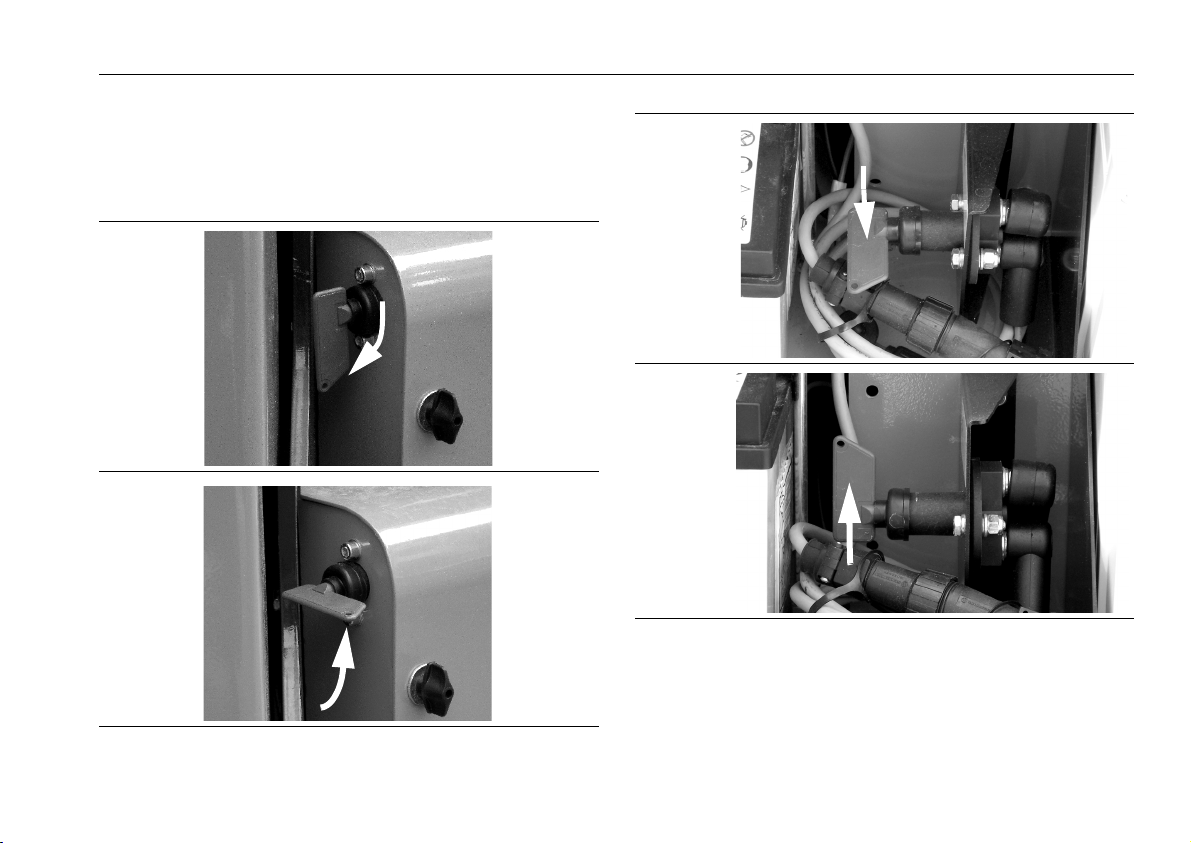
SECTION 4 - MACHINE OPERATION
7. If machine is to be shut down for long periods of
time, turn the battery disconnect switch, RED handle
located on the electrical/battery tray housing, to the
POWER OFF position. (photos below and next page)
POWER ON
Clockwise
POWER OFF
CounterClockwise
POWER ON
Clockwise
POWER OFF
CounterClockwise
BATTERY DISCONNECT - LITHIUM-ION - ELECTRIC
(Mounted Inside Left-Side Electrical Component Compartment)
BATTERY DISCONNECT - GAS/DIESEL/AC-ELECTRIC
3128791 – JLG Lift – 4-23

SECTION 4 - MACHINE OPERATION
1
1
4.11 LIFTING AND TIE DOWN
Lifting
1. Determine gross weight of machine, refer to the
serial number tag, or weigh the individual unit to find
out the gross vehicle weight.
2. Place the booms in the stowed position and properly
aligned. All outriggers are fully retracted and the
tracks are fully widened.
3. Remove all loose items from the machine.
4. Properly adjust the rigging to prevent damage to the
machine and so the machine remains level.
5. The width of the slings must not exceed 2.36 in. (60
mm), the width of the chains must not exceed .984
in. (25 mm), the diameter of the ropes must not
exceed .984 in. (25 mm) in order not to exert a pressure in an abnormal direction on the outrigger plate.
THE USE OF ROPES, CHAINS OR SLINGS WITH LENGTH LESS THAN
10 ft. (3m) COULD CAUSE PERMANENT DAMAGE TO THE MACHINE
OUTRIGGERS.
To lift the machine a separate sling must be attached to each
outrigger using the appropriate lifting points as indicated in the
photo.
As the weight of the machine is not spread equally over the
four outriggers, the minimum required capacity of the four
ropes, chains or slings used must be: no less than 4,409 lb.
(2000 kg) and their length no less than 10 ft. (3m) and all iden-
tical.
Figure 4-5. Lifting Machine - Attach Points
1. Lifting Slings
4-24 – JLG Lift – 3128791

SECTION 4 - MACHINE OPERATION
Tie Down
(See Figure 4-6.)
WHEN TRANSPORTING THE MACHINE, THE BOOM MUST BE FULLY
LOWERED INTO THE BOOM REST.
• Travel up ramps with the platform behind the machine.
• Do not contact the ground with the jib or bottom of platform when loading/unloading. Operate the machine
from the ground remote position and raise the jib to prevent contact with the ground. See “Jib Position for Travelling” on page 4-9.
• ALWAYS load/unload the machine with the track fully
widened.
1. Place the booms in the stowed position.
2. Remove all loose items from the machine.
3. Secure the chassis using straps or chains of ade-
quate strength.
DO NOT MAKE CONNECTIONS AT POINTS DIFFERENT THAN
THOSE IDENTIFIED BY THE TIE DOWN LOCATION DECAL SHOWN.
THIS COULD CAUSE PERMANENT DAMAGE RESULTING IN THE
COLLAPSE OF THE PRODUCT.
3128791 – JLG Lift – 4-25

SECTION 4 - MACHINE OPERATION
1
2
2
1
Figure 4-6. Machine Tie-Down Points (both sides of machine)
1. Tie-Down Loop 2. Tie-Down Decal
4-26 – JLG Lift – 3128791

4.12 MACHINE DECALS
SECTION 4 - MACHINE OPERATION
Figure 4-7. Decal installation - Standard - Right Side
3128791 – JLG Lift – 4-27

SECTION 4 - MACHINE OPERATION
Figure 4-8. Decal Installation - Standard - Left Side
4-28 – JLG Lift – 3128791

SECTION 4 - MACHINE OPERATION
Table 4-1. X550AJ - Decal Installation - Standard (See Figure 4-7. and Figure 4-8.)
ITEM # PART NUMBER DESCRIPTION
DECAL INSTALLATION
1 1706128 Decal, Danger - Electrocution Hazard - Maintain Distance From Electric Lines
2 1001125483 Decal, No Pressure Washing At This Location
3 07050300 Decal, Machine Maximum Capacity/Side Force - Jib Extended/Retracted
4 WIP Decal, Hand Pump Manual Descent Instructions
5 07042000 Decal, Machine Gross Weight
6 07042400 Decal, Outrigger Pad - Ground Pressure
7 07042600 Decal, 1m/3.3 ft. - Safe Working Distance When Operating M ach ine From Ground
8 06942200 Decal, Ground Key Switch Mode Selector
9 07045200 Decal, Ground Control Station - Control Valve - Manual Operation
10 07045100 Decal, Left Side - Outrigger/Drive/Steer - Manual Control Valve Operation
11 07045000 Decal, Right Side - Outrigger/Drive/Steer/Track Width - Manual Control Valve Operation
12 — Not Used
13 06555500 Decal, Outrigger Number 1
14 06555600 Decal, Outrigger Number 2
15 1701640 Decal, Manual
16 07056100 Decal, Warning - Boom Crushing Hazard
17 1702901 Decal, Manual Descent Instructions Inside
18 07056200 Decal, Warning - Crushing Hazard - Outrigge Pad
19 07056400 Decal, 120V - 50/60HZ - Electrical
20 07071200 Decal, Machine Lifting Point
21 06040500 Decal, Forward Travel Direction
22 1704277 Decal, Lanyard Attach Point
3128791 – JLG Lift – 4-29

SECTION 4 - MACHINE OPERATION
Table 4-1. X550AJ - Decal Installation - Standard (See Figure 4-7. and Figure 4-8.)
ITEM # PART NUMBER DESCRIPTION
23 — Not Used
24 1702155 Decal, Batter y Disconnect
25 06555700 Decal, Outrigger Number 3
26 06555800 Decal, Outrigger Number 4
27 — Not Used
28 — Not Used
29 07061900 Decal, X550AJ - Model Designation
30 06039700 Decal, Outrigger - Hazard Stripe
31 06086700 Decal, Platform Hazard Stripe
32 06039900 Decal, Outrigger - Hazard Stripe
33 06087400 Decal, Platform Hazard Stripe
1701505 Decal, Diesel Fuel Only
34 07060500 Decal, JLG Logo
35 — Not Used
36 06040200 Decal, Hydraulic Pump - Left/Right Side - Diverter Valve
37 — Not Used
38 06087700 Decal, Tower Boom End - Hazard Stripe
39 06087600 Decal, Tower Boom End - Hazard Stripe
40 06087500 Decal, Tower Boom End - Hazard Stripe
41 06087900 Decal, Tower Boom End - Hazard Stripe
42 1701504 Decal, Warning - Hydraulic Fluid Under Pressure
43 07042100 Decal, Boom Functions Safety System Bypass (Key Switch)
44 07042200 Decal, Drive Functions Safety System Bypass (Key Switch)
45 1703814 Decal, Machine Tie Down Location
4-30 – JLG Lift – 3128791

SECTION 4 - MACHINE OPERATION
Table 4-1. X550AJ - Decal Installation - Standard (See Figure 4-7. and Figure 4-8.)
ITEM # PART NUMBER DESCRIPTION
46 — Not Used
47 1701499 Decal, Not A Machine Lif ting Point
48 07060700 Decal, JLG Lift Logo
49 — Not Used
50 — Not Used
51 1701499 Decal, Not A Machine Lif ting Point
52 — Not Used
53 06706500 Decals, Boom/Base Alignment Arrow
54 — Not Used
55 — Not Used
56 07051100 Decal, Warning - Fall Hazard - Platform Mounting Caps
57 07051000 Decal, Warning - Fall Hazard - Platform Mounting Caps
58 06165000 Decal, Hydraulic Oil Tank - Fluid Level Check
59 06056300 Decal, Danger - Hot Surface
60 — Not Used
61 — Not Used
62 1706898 Decal, Ground Control Emergency Stop Button
63 07045300 Decal, Ground Control Key Switch
64 — Not Used
65 1701542 Decal, Gasoline Fuel Only
1701505 Decal, Diesel Fuel Only
66 06232100 Decal, Warning - Gasoline - Flammable/Explosive
67 06060000 Decal, Check Motor Oil Level
68 — Not Used
3128791 – JLG Lift – 4-31

SECTION 4 - MACHINE OPERATION
Table 4-1. X550AJ - Decal Installation - Standard (See Figure 4-7. and Figure 4-8.)
ITEM # PART NUMBER DESCRIPTION
69 1706386 Decal, Warning - Fall Hazard - Platform
70 1706387 Decal, Warning - Crushing Hazard - Platform
71 1706133 Decal, Warning - Tip-Over Hazard - Platform
72 07058600 Decal, Warning - Tip-Over Hazard - Platfor m
73 1706385 Decal, Warning - Fall Hazard - Platform Gate
74 1706135 Decal, Warning - Ground Control Instructions
75 706099 Decal, Warning - Boom Crushing Hazard - Ground Controls
76 3252347 Decal, Warning - Platform Foot Switch
77 1702868 Decal, Caution - No Hands or Lanyard - Platform Rail
78 1703813 Decal, Warning - Battery Charging Ventilation - Explosion/Fire Hazard
79 1704972 Decal, Warning - Diesel Engine - Explosion/Fire Hazard - Glow Plugs/Star ting Fluid
80 1702961 Decal, Warning - Engine Exhaust Hazard
1702962 Decal, Califor nia Prop 65 Warning
81 1705514 Decal, CSA B354.4-02
82 07050700 Decal, NOT A Lanyard Attach Point
83 07071000 Decal, Platform Horn
4-32 – JLG Lift – 3128791

SECTION 4 - MACHINE OPERATION
Figure 4-9. Decal installation - Lithium-Ion - Left Side
3128791 – JLG Lift – 4-33

SECTION 4 - MACHINE OPERATION
Figure 4-10. Decal Installation - Lithium-Ion - Right Side
4-34 – JLG Lift – 3128791

SECTION 4 - MACHINE OPERATION
Table 4-2. X550AJ - Decal Installation - Lithium Machine (See Figure 4-9. and Figure 4-10.)
ITEM # PART NUMBER DESCRIPTION
DECAL INSTALLATION
1 06520600 Decal, Operating Decibel Level
2 07110200 Decal, Emergency Descent Instructions
3 07107200 Decal, Warning - Batter y Hazard
4 1001125483 Decal, Do Not Pressure Wash
5 06506400 Decal, Power ON/OFF Key Switch
6 07107100 Decal, Recharge Batteries After Each Use or At Least Every 3 Months
3128791 – JLG Lift – 4-35

SECTION 4 - MACHINE OPERATION
NOTES:
4-36 – JLG Lift – 3128791

SECTION 5 - EMERGENCY PROCEDURES
SECTION 5. EMERGENCY PROCEDURES
5.1 GENERAL
This section explains the steps to be taken in case of an
emergency situation while operating.
5.2 INCIDENT NOTIFICATION
JLG Industries, Inc. must be notified immediately of any
incident involving a JLG product. Even if no injury or
property damage is evident, the factory should be contacted by telephone and provided with all necessary
details.
In USA JLG Phone: 877-JLG-SAFE (554-7233)
(8am till 4:45pm EST)
Outside USA: 240-420-2661
E-mail: ProductSafety@JLG.com
Failure to notify the manufacturer of an incident involving
a JLG Industries product within 48 hours of such an
occurrence may void any warranty consideration on that
particular machine.
FOLLOWING ANY ACCIDENT, THOROUGHLY INSPECT THE
MACHINE AND TEST ALL FUNCTIONS FIRST FROM THE GROUND
CONTROLS, THEN FROM THE PLATFORM CONTROLS. DO NOT LIFT
ABOVE 10 FT. (3M) UNTIL YOU ARE SURE THAT ALL DAMAGE HAS
BEEN REPAIRED, IF REQUIRED, AND THAT ALL CONTROLS ARE
OPERATING CORRECTLY.
5.3 EMERGENCY OPERATION
Power Main Cut-Off Switch Location
A battery cut-off switch - RED handle (photo shows power
OFF) is located on the outside of the battery/electrical box
tray at the left front of the machine just behind the outrigger
mount. When switched off - handle turn all the way in direction of arrow - all electrical power to the machine is shut
down.
Gas/Diesel/AC-Electric Lithium-Ion-Electric
3128791 – JLG Lift – 5-1

SECTION 5 - EMERGENCY PROCEDURES
Operator Unable to Control Machine
IF THE PLATFORM OPERATOR IS PINNED, TRAPPED
OR UNABLE TO OPERATE OR CONTROL MACHINE:
1. Other personnel should operate the machine from
ground controls only as required.
2. Other qualified personnel on the platform may use the
platform controls. DO NOT CONTINUE OPERATION IF
CONTROLS DO NOT FUNCTION PROPERLY.
3. Cranes, forklift trucks or other equipment can be used
to remove platform occupants and stabilize motion of
the machine.
Platform or Boom Caught Overhead
If the platform or boom becomes jammed or snagged in
overhead structures or equipment, rescue platform occupants prior to freeing the machine.
NOTE: The engine runs the hydraulic pump which provides
the hydraulic pressure for the hydraulic system.
The electric power provides power for the hydraulic
proportional valve solenoids to open and close which
operate various solenoids and relays on the hydraulic
system. In the event either/or both are not operating
properly, the following procedures will allow the lowering of the boom and platform.
Manual Descent with Engine Running and Electrical Power
ENSURE BOOM IS NOT POSITIONED OVER THE OUTRIGGERS OR
OVERHEAD OF PERSONNEL BEFORE LOWERING.
Using Platform/Remote Control Box from Platform
(See Figure 5-1.)
The manual descent system is provided as an emergency
means to lower personnel in the platform.
1. Check that the emergency stop button is in the ON posi-
tion by turning it clockwise.
2. Depress the platform foot switch.
3. Press and hold down button 4 (item 4) with
the hazard symbol on the platform/remote
control box. The LCD display (item 14) will
indicate the triangle symbol seen on the button in LCD position 8.
4. Select a boom function to operate by moving it’s con-
troller in the direction for lowering. (items 16, 17, and 20)
5. When finished, release the emergency lowering switch
(item 4), and foot switch.
6. Position (press) the emergency stop switch to the OFF
position.
5-2 – JLG Lift – 3128791
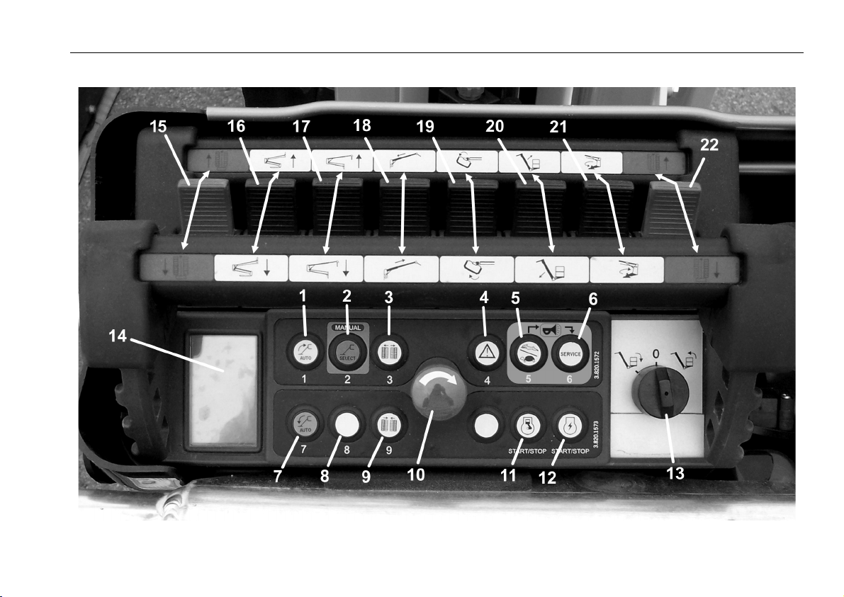
SECTION 5 - EMERGENCY PROCEDURES
Figure 5-1. Platform/Remote Control Station
3128791 – JLG Lift – 5-3

SECTION 5 - EMERGENCY PROCEDURES
Using Emergency/Ground Controls from Ground
(See Figure 5-2.)
ENSURE BOOM IS NOT POSITIONED OVER THE OUTRIGGERS OR
OVERHEAD OF PERSONNEL BEFORE LOWERING.
1. Be certain the emergency stop button (item 1) is in the
ON position by turning it clockwise.
2. Start the engine, if not already running.
3. At the Emergency/Ground Control box, turn the key
switch (item 2) all the way clockwise and hold.
4. Check that the green (machine stabilized) indicator light
(item 4) on the Emergency/Ground Control box is on.
5. Operate the appropriate manual control lever (item 5, 6,
7, or 8) next to it’s proportional valve under the cover of
the valve distributor. See decal on valve distributor cover
for boom component and direction to operate lever for
desired movement.
6. When finished, release the key switch (item 2) back to
the neutral position.
7. Position (press) the emergency stop switch (item 1) to
the OFF position.
5-4 – JLG Lift – 3128791

SECTION 5 - EMERGENCY PROCEDURES
Figure 5-2. Ground Control Station - Boom Control Valves
3128791 – JLG Lift – 5-5

SECTION 5 - EMERGENCY PROCEDURES
1
Manual Descent with Engine Running but without Electrical Power (Combustion Engines Only)
(See Figure 5-3.)
ENSURE BOOM IS NOT POSITIONED OVER THE OUTRIGGERS OR
OVERHEAD OF PERSONNEL BEFORE LOWERING.
1. Remove the cover from the electrical components tray
on the left side of the machine.
2. Locate and remove the proportional valve adjustment
knob from the protective plastic bag,
3. Slide the adjustment knob assembly onto the propor-
tional valve stem (item 1) located next to the electric
engine.
NOTE: The proportional valve adjusts the speed of the boom
movements (pressure flow) when using the boom
control valves at the valve distributor on the left side of
the machine in Figure 5-2. Without electrical power
you must manually open this valve with the adjustment
knob before operating the boom controls.
4. Turn the proportional valve adjustment knob clockwise
approximately four turns, the more turns the valve is
open the faster the movement of the boom component.
Always carry out movement at the slowest possible
speed.
5. Operate the boom control valves at the ground control
valve distributor. (see Figure 5-2.)
6. Make boom movements in the following sequence:
• fully retract main boom
• fully lower jib
• fully lower tower boom
• fully lower main boom
Figure 5-3. Main Flow Control Valve Location
7. When emergency operation is complete, loosen knob
on the proportional valve completely, remove it and
place it back in the protective bag.
5-6 – JLG Lift – 3128791

Manual Descent without Engine and Electrical
1
2
Power
Using Hand Pump in Hydraulic Compartment on Right
side of Machine
1. Platform retrieval sequence.
Ensure the machine is level and all outriggers are properly deployed on a firm surface.
a. Remove the cover from the electrical components
tray on the left side of the machine.
b. Locate and remove the proportional valve adjust-
ment knob from the protective plastic bag,
c. Slide the adjustment knob assembly onto the pro-
portional valve stem (item 1 - Figure 5-3.) located
next to the electric engine.
d. Open the flow valve by turning the thumbwheel in
the clockwise direction until it stops.
e. Locate the pump handle secured to the side of the
boom assembly directly behind the hand pump.
f. Install the pump handle on the pump (item 1 - Figure
5-4.) and secure in place with the provided screw.
The lever (item 2 - Figure 5-4.) on the pump must be
set to the left.
SECTION 5 - EMERGENCY PROCEDURES
Figure 5-4. Hand Pump - On Top Of Hydraulic Tank
NEVER WORK UNDER AN ELEVATED PLATFORM UNTIL PLATFORM
HAS BEEN SAFELY RESTRAINED FROM ANY MOVEMENT BY
BLOCKING OR OVERHEAD SLING.
NEVER REACH THROUGH, UNDER, OR OVER THE BOOM' S PATH
OF TRAVEL TO THE GROUND CONTROL PANEL. IF NO ASSISTANT
IS AVAILABLE, PROCEED WITH THE FOLLOWING STEPS.
3128791 – JLG Lift – 5-7

SECTION 5 - EMERGENCY PROCEDURES
1
TO AVOID CONTACT BETWEEN THE JIB AND OUTRIGERS, DO NOT
ATTEMPT TO MANUAL SWING WITH THE BOOMS AND JIB FULLY
LOWERED.
2. Swing turntable inline with the chassis so that the turnta-
ble and base indicator arrows are aligned.
NOTE: This will eliminate the possibility of an elevated or
extended boom being positioned overhead of personnel at the pump and eliminate the risk of lowering the
jib onto an outrigger.
a. Activate the swing control lever located next to the
main flow control valve (see photo below - item 1), in
the desired direction of travel while pumping the
hand pump until the turntable is aligned with the
chassis.
b. Activating the lever rearward while pumping will
swing the platform to the left.
Activating the lever forward while pumping will swing
the platform to the right.
3. Retract the main boom (if necessary).
With the aid of an assistant, while pumping the hand
pump, activate the telescope function lever (Item 7, Fig-
ure 5-2.) at the ground controls, to retract the main
boom.
4. Lower the jib.
While pumping the handpump, activate the jib lift function lever (item 8, Figure 5-2.) in the appropriate direction to lower the jib.
5. Lower the Tower Boom
While pumping the handpump, activate the tower boom
lift function lever (item 5, Figure 5-2.) in the appropriate
direction to lower the tower boom.
6. Lower the Main Boom
With the aid of an assistant, activate the main boom lift
function lever (item 6, Figure 5-2.) in the appropriate
direction to lower the main boom.
7. Rotate the platform (if necessary).
Activate the appropriate platform rotate function button
to rotate the platform.
5-8 – JLG Lift – 3128791

SECTION 5 - EMERGENCY PROCEDURES
8. Level the platform (if necessary).
Activate the appropriate platform level function button to
level the platform.
9. Completely unscrew (counterclockwise) the black thum-
bwheel from the diverter valve until it stops. Remove the
thumbwheel from the shaft of the diverter valve.
10. Remove the manual pump handle from the pump and
secure to turntable in its original position.
Outrigger/Track Movement Emergency Procedure:
Outrigger/Track Movement Using the Hand Pump on
Right Side of Machine
PLACE THE MACHINE INTO TRANSPORT CONFIGURATION ONLY
AFTER HAVING ALIGNED AND FULLY LOWERED AND RETRACTED
THE BOOM AND JIB.
WHEN RETRACTING THE OUTRIGGERS, THE MACHINE CAN
BECOME UNBALANCED IF ONE OR MORE OUTRIGGERS ARE OFF
OF THE GROUND AT ANY ONE TIME. RETRACT OUTRIGGERS
EQUALLY, TO KEEP MACHINE BALANCED.
Outrigger Functions:
1. At the rear of the chassis, locate the three valve and four
valve group of manual override buttons. The manual
override buttons on these valves provide access to the
right and left side outrigger and right and left track functions.
2. Locate the pump handle secured to the side of the
boom assembly directly behind the hand pump.
3. Install the pump handle on the pump and secure in
place with the provided screw. (item 3 - Figure 5-4.)
The lever on the pump must be set to the right to manually operate right side outrigger and track functions.
3128791 – JLG Lift – 5-9

SECTION 5 - EMERGENCY PROCEDURES
For right side (operator's perspective) Outrigger
and Track Functions:
4. Locate the proportional flow valve on the right side of
the chassis attached to the group of four valves (item 1 Figure 5-5.). Turn the black knob on the valve clockwise
(tighten) until it stops.
5. With the aid of an assistant, activate the pushbutton for
the desired direction on the appropriate valve solenoid
(valve description below) while pumping the pump handle to achieve the desired function movement.
NOTE: If no assistant is available, the black pushbuttons on
the solenoids may be unscrewed to allow installation
of the valve tool on the solenoids.
•1st valve (item 2 - Figure 5-5.) (far right - right side of
machine in the group of four) operates Right Rear
Outrigger
• 2nd valve (item 3 - Figure 5-5.) from the right in the
group of four operates Right Front Outrigger
•3rd valve (item 4 - Figure 5-5.) from the right in the
group operates the Right Track Drive functions.
•4th valve (item 5 - Figure 5-5.) from right in the group
of four, operates track extension and retraction.
For left side (operator's perspective) Outrigger and
Track Functions
6. Locate the proportional flow valve on the left side of the
chassis attached to the group of three valves (item 6 Figure 5-5.). Turn the black knob on the valve clockwise
(tighten) until it stops.
7. Install valve tool on diverter solenoid on left side near
rear outrigger.
8. The lever on the pump (item 2 - Figure 5-4.) must be set
to the left to manually operate left side outrigger and
track functions.
9. With the aid of an assistant, activate the pushbutton for
the desired direction on the appropriate valve solenoid
5-10 – JLG Lift – 3128791

SECTION 5 - EMERGENCY PROCEDURES
while pumping the handle to achieve the desired function movement.
NOTE: If no assistant is available, the black thumbscrews on
the solenoids may be unscrewed to allow installation
of a second valve tool on the solenoids.
•1st valve (item 7 - Figure 5-5.) (far right (at rear of
machine) in the group of three) operates Left Front
Outrigger.
• 2nd valve (item 8 - Figure 5-5.) from the right in the
group of three operates Left Rear Outrigger.
•3rd valve (item 9 - Figure 5-5.) from the right in the
group of three valves operates the Left Track Drive
functions.
1. When manual operation is complete, remove (if neces-
sary) the valve tool(s), unscrew the proportional flow
valve black knob and reinstall any valve solenoid retaining thumbscrews or pushbuttons.
2. Remove the manual pump handle from the pump and
secure it in its original position.
3128791 – JLG Lift – 5-11

SECTION 5 - EMERGENCY PROCEDURES
1
2
3
5-12 – JLG Lift – 3128791
Figure 5-5. Ground Component Valves - Outriggers/Steer/Tracks - Location

SECTION 5 - EMERGENCY PROCEDURES
1
2
5.4 SAFETY DEVICES BYPASS KEY USE
THIS FEATURE MUST ONLY BE USED AS DESCRIBED BELOW. THE
MACHINE COULD TIP OVER IF THESE DIRECTIONS ARE NOT FOLLOWED.
The machine has a key for bypassing the platform safety
systems. The key used to activate the safety device bypass
switch (item 2 - photo), is fastened to the cover attach screw
mounting tab from the factory (item 1 - photo), on the left
side of the electrical components compartment near the battery.
Remove the key and insert it into the bypass
key switch (item 2 - photo). After using the
safety device bypass, a qualified JLG mechanic
must be contacted to determine the reason for
needing to use this feature. Return the key to the where you
found it and secure it in that location.
The safety device circuit board records every time the safety
device bypass key is activated along with the movements
made during these operations.
THE SAFETY DEVICE BYPASS ALLOWS OPERATION OF THE
MACHINE WITH AN OVERLOAD IN THE PLATFORM. THE OVERLOAD ALARM WILL SOUND AND THE OVERLOAD ICON WILL BE
ON THE PLATFORM/REMOTE CONTROL BOX DISPLAY. REMOVE
THE OVERLOAD FROM THE PLATFORM BEFORE OPERATION.
3128791 – JLG Lift – 5-13

SECTION 5 - EMERGENCY PROCEDURES
Using The Emergency Descent In The Case Of An Outrigger Losing Contact With The Ground
One or more of the outriggers may loose contact with the
ground which will result in the platform/remote control box
functions being inoperable except for emergency lowering.
To restore platform/remote control box functions, lower and
retract the booms and then reposition the machine and
properly set the outriggers.
Use the emergency descent from the platform if possible by
using the following sequence, fully retract main boom, fully
lower jib, fully lower tower boom, and fully lower main boom.
If this is not possible, have a properly trained person on the
ground bypass the platform safety devices and allow the
operator in the platform to lower and retract the booms or
allow emergency manual operations to bring the platform
back to the ground.
1. Locate and use the safety device bypass key as stated
above.
2. Activate the safety device bypass by turning the key in a
counterclockwise direction and hold it in position (see
decal).
3. The safety devices BYPASS icon will appear
on the platform/remote control box display.
4. Operate the machine from the platform/remote control
ONLY carrying out operations that allow the tower boom
lowering, main boom retract and jib lowering. The main
boom must be fully retracted prior to operating swing
and main boom lowering functions.
NEVER PERFORM OPERATIONS DIFFERENT TO THOSE LISTED OR
THAT CAN IN SOME WAY REDUCE THE STABILITY OF THE
MACHINE. THE ORDER OF THE BOOM MOVEMENTS MUST BE
DONE IN A WAY TO PREVENT ANY OPERATION THAT REDUCES
THE STABILITY OF THE MACHINE.
5. Once the booms and jib are fully lowered and aligned,
release the key and follow the instructions above to
secure the key.
5-14 – JLG Lift – 3128791

SECTION 5 - EMERGENCY PROCEDURES
Machine Realignment Emergency Procedure
THIS OPERATION MUST ONLY BE PERFORMED WITH
THE BOOMS AND JIB FULLY LOWERED AND
RETRACTED.
During transport, the turntable may swing and become out
of alignment with the base. If this occurs, one of the two
EMERGENCY PROCEDURES given below can be used:
Machine Realignment:
1. Open the electric components compartment;
2. Locate and use the safety device bypass key as
described above;
3. Activate the safety device bypass by turning the key in a
counterclockwise direction and holding it in position
(see decal beside keyswitch);
4. The safety devices BYPASS icon will appear
on the platform/remote control box LCD
display.
5. Realign the machine while operating the
swing function from the platform/remote control box.
6. Once the machine is aligned, release the key and store
it as stated above.
Movement Of The Tracks With The Machine Not Aligned:
OPERATION ONLY ALLOWED TO GO TO A CONDITION
SUITABLE TO CARRY OUT THE PROCEDURE INDICATED IN "MACHINE REALIGNMENT" ABOVE. ALL
OTHER USE IS PROHIBITED.
1. Open the electric components compartment;
2. Locate and use the safety device bypass key as
described above;
3. Activate the safety device bypass key by turning it in a
clockwise direction and holding it in position (see
decal);
4. The safety devices BYPASS icon will appear
on the platform/remote control box display.
5. Operate the drive/steer controls with
extreme caution.
6. Move the machine to a proper location to perform
"Machine Realignment" procedure to realign the
machine.
7. At the end of the operation release the key and store it
as is described above.
The control circuit board records every activation of the
safety device bypass key.
3128791 – JLG Lift – 5-15

SECTION 5 - EMERGENCY PROCEDURES
5.5 LITHIUM-ION BATTERY PACK - HANDLING IN DANGEROUS CONDITIONS
The battery cells must be handled correctly in order to ensure
proper and safe use. However, if mistakes are made in handling the cells, causing explosion or venting, the user has to
be equipped so as to be able to face this emergency. The aim
of this section is to adequately train the user on safe handling
of the cells that have been subjected to extreme conditions.
These Conditions Are As Follows:
1. Hot cells
2. Cells that have released substances or vented
3. Exploded cells
4. Fire enveloping the lithium batteries
Procedure For Handling Hot Cells
As soon as it has been established that the temperature of a
cell has risen considerably, the first action is the evacuation of
personnel from the affected area. The area has to be isolated
and nobody can enter if not strictly necessary.
If possible, before leaving the area, the person who first identified the problem has to check if there is an external short-circuit and resolve it as soon as possible. After the short-circuit
has been resolved, the cell will start to cool down. However,
the area has to remain isolated until the cell reaches ambient
temperature and is removed from the area. The temperature
of the cell has to be checked periodically using a remote sensor such as an infrared sensor. If the cell remains hot the following actions must be assessed.
Minimum Equipment Required:
• Infrared temperature probe
• Safety glasses
• Hard hat with impact resistant face visor
• Non-conductive pliers
• Hand, arm and body protection
5-16 – JLG Lift – 3128791

SECTION 5 - EMERGENCY PROCEDURES
Start Procedure;
1. Evacuate the area as soon as abnormal cell temperature
has been established.
2. Periodically check the temperature of the cell using a
remote sensor for the first two hours or until one of the
following cases occur:
• The cell starts to cool down
• The cell vents
• The cell explodes
3. If the cell starts cooling, check the temperature every
hour until ambient temperature has been reached.
4. If a temperature sensor is not available, do not handle
the cell for a minimum of 24 hours.
5. Remove the cell from the work area when ambient tem-
perature has been reached and return to normal operations.
6. Dispose of the cell in accordance with existing legislation
(in the country in question) on hazardous materials.
The procedures in cases of venting or explosion are examined
in the following paragraphs.
Procedure For Handling Vented Cells
In normal conditions a cell does not show leaks or venting,
however a cell may vent or release substances if the critical
temperature is reached or if the protective glass.metal seal
breaks due to severe mechanical conditions.
The severity of the leak consequent to venting ranges from
slight leak around the seal to a violent leak of substances
through the vent. In some cases, if the cell is not plugged, it
may behave as a projectile.
The electrolyte inside the cell may cause very serious irritation to the respiratory tract, eyes and skin. In addition, venting
may cause the emission of highly corrosive vapors in the
work environment. In this case, all protective equipment
suited to limit exposure to toxic fumes must be available.
Minimum Equipment Required;
• Class D fire extinguisher
• Eye protection or face shield
• Respirator with filter for hydrochloric acid and sulphur
dioxide
• Neoprene gloves
• Acid.resistant lab coats
• Baking soda, calcium oxide or acid absorbent in kit form
•Vermiculite
•Plastic bags
3128791 – JLG Lift – 5-17

SECTION 5 - EMERGENCY PROCEDURES
Start Procedure;
In the event of electrolyte release from the cells, proceed as
follows:
1. Evacuate the people exposed to fumes from the area.
2. Air the environment until the complete removal of the cell
and until the characteristic pungent odour has disappeared.
3. If the cell is too hot, allow it to cool to ambient tempera-
ture before handling it (see “Procedure For Handling Hot
Cells” on page 16).
4. Wear safety equipment: coat, gloves, mask and filters,
and move the cell to a well-ventilated area.
5. Place every cell in a sealable plastic bag and remove the
excess air, then seal the bag.
6. Place a cup of vermiculite in a second bag, place the first
bag in the second and seal it.
7. Place everything in a third bag with some baking soda
and seal the bag.
8. Absorb and collect the leaked electrolyte with absorbent
material or baking soda.
9. Place the absorbent material in a bag and seal it.
10. Clean the area with plenty of water.
11. Dispose of the hazardous material in accordance with
the local legislation in force.
First Aid In The Event Of Contact With The Electrolyte
EYES
Immediately wash the eyes in abundant running water for at
least 15 minutes, keeping the eyelids open and flushing the
eye and back of the eyelid. Immediately seek medical help.
SKIN
Wash in cold water under a shower, remove contaminated
garments. Continue washing for at least 15 minutes. Seek
medical help where necessary.
RESPIRATORY TRACT
Move the person(s) outdoors into the open air. If the person(s) has difficulty breathing, have oxygen administered by
trained personnel. If breathing stops, apply mouth-to-mouth
resuscitation and immediately seek emergency medical help.
5-18 – JLG Lift – 3128791

SECTION 5 - EMERGENCY PROCEDURES
Procedure For Exploded Cells
The explosion of lithium batteries is not likely, it is a rare event
that only occurs when an abnormal condition causes the temperature to rise and reach a critical point. However, in the
event of lithium battery explosion the environment will quickly
be filled with dense white smoke which will cause serious irritation to the respiratory tract, eyes and skin. Precautions
must be taken to limit exposure to these fumes.
Minimum Equipment Required;
• Class D fire extinguisher
• Class ABC extinguisher for any secondary fires
• Eye protection or face shield
• Respirator with filter for hydrochloric acid and sulphur
dioxide
• Neoprene gloves
• Acid.resistant lab coats
• Baking soda, calcium oxide or acid absorbent in kit form
•Vermiculite
•Plastic bags
Start Procedure;
In the event of cell explosion, proceed as follows:
1. Evacuate personnel from the areas contaminated by
smoke.
2. Ventilate the rooms until the cell has been removed from
the area and until the characteristic pungent odour has
disappeared.
3. Even if this is quite unlikely, there may be fires as a con-
sequence of the explosion. The ways these emergencies
are faced are described in the following paragraph.
4. The exploded cell may be hot. Allow it to cool down to
ambient temperature before handling it (see Procedure
for handling hot cells).
5. Wear safety equipment: coat, gloves, mask and filters.
6. In case of explosion the area around the cell will be cov-
ered by a black carbonaceous material which contains
metallic parts of the cell. Cover the carbonaceous residues with a 50/50 mixture of baking soda and vermiculite
or other absorbent material. Avoid contact between the
metallic residues and charged cells, as this condition
may cause a short.circuit.
7. Place the contaminated material in a sealable plastic bag
and remove the excess air.
8. Seal the bag.
3128791 – JLG Lift – 5-19

SECTION 5 - EMERGENCY PROCEDURES
9. Place a cup of vermiculite in a second bag, place the first
bag in the second and seal it.
10. Clean the area with plenty of water and keep cleaning
with water and soap.
11. Dispose of the hazardous material in accordance with
the local legislation in force.
First Aid In The Event Of Contact With The Electrolyte;
EYES
Immediately wash the eyes in abundant running water for at
least 15 minutes, keeping the eyelids open and flushing the
eye and back of the eyelid. Immediately seek medical help.
SKIN
Wash in cold water under a shower, remove contaminated
garments. Continue washing for at least 15 minutes. Seek
medical help where necessary.
RESPIRATORY TRACT
Move the casualty outdoors into the open air. If the person(s)
has difficulty breathing, have oxygen administered by trained
personnel. If breathing stops, apply mouth-to-mouth resuscitation and immediately seek emergency medical help.
Lithium Battery Fire
All metals may burn in certain conditions, which depend on
certain factors such as: physical state, presence of oxidising
atmospheres and severity of the source of ignition. Alkali metals such as lithium may burn in normal atmospheres. In addition, lithium reacts explosively with water to form hydrogen
and the presence of small quantities of water may set fire to
the material and the hydrogen gas that is released. Once
metal fires start they are very hard to extinguish with ordinary
equipment. This is partly due to the strong heat produced by
the burning metal, whose temperature may reach 1832° F
(1000° C). In addition, lithium may react with certain materials
commonly used in fire extinguishers, like water and CO2.
Special extinguishers are required, designed for controlling
and extinguishing lithium fires.
In particular, graphite-based extinguishers (Lith-x) are used.
Usually these extinguishers work by forming a crust or a layer
of material on the surface of the burning metal. Lith-x, which
is a common graphite-based agent, may be used with an
extinguisher or spread over the fire. In the event of lithium fire,
the room may fill with a dense white smoke, mostly formed by
lithium oxide and other metal oxides. This condition may
cause serious damage to the respiratory tract, skin and eyes.
All precautions needed to limit exposure to these fumes must
be adopted. It should be noted that this procedure is applicable only to fires on individual cells. Larger fires have to be
managed only by professionally trained personnel.
5-20 – JLG Lift – 3128791
 Loading...