


 Loading...
GE Fanuc Automation
Computer Numerical Control Products
Laser C1000 / C2000 / C4000―Model E
Maintenance Manual
GFZ-70265EN/01 |
February 2001 |

GFL-001
Warnings, Cautions, and Notes as Used in this Publication
Warning
Warning notices are used in this publication to emphasize that hazardous voltages, currents, temperatures, or other conditions that could cause personal injury exist in this equipment or may be associated with its use.
In situations where inattention could cause either personal injury or damage to equipment, a Warning notice is used.
Caution
Caution notices are used where equipment might be damaged if care is not taken.
Note
Notes merely call attention to information that is especially significant to understanding and operating the equipment.
This document is based on information available at the time of its publication. While efforts have been made to be accurate, the information contained herein does not purport to cover all details or variations in hardware or software, nor to provide for every possible contingency in connection with installation, operation, or maintenance. Features may be described herein which are not present in all hardware and software systems. GE Fanuc Automation assumes no obligation of notice to holders of this document with respect to changes subsequently made.
GE Fanuc Automation makes no representation or warranty, expressed, implied, or statutory with respect to, and assumes no responsibility for the accuracy, completeness, sufficiency, or usefulness of the information contained herein. No warranties of merchantability or fitness for purpose shall apply.
©Copyright 2001 GE Fanuc Automation North America, Inc.
All Rights Reserved.

B-70265EN/01 TABLE OF CONTENTS
TABLE OF CONTENTS
1 OVERVIEW......................................................................................................................................... |
1 |
|
1.1 |
ORGANIZATION OF THE MANUAL ............................................................................................. |
2 |
1.2 |
APPLICABLE MODELS................................................................................................................... |
3 |
1.3 |
RELATED MANUALS...................................................................................................................... |
4 |
1.4 |
TO USE THE LASER OSCILLATOR SAFETY .............................................................................. |
5 |
2 SAFETY .............................................................................................................................................. |
6 |
|
2.1 |
WARNING ......................................................................................................................................... |
7 |
2.2 |
CAUTION ........................................................................................................................................ |
10 |
2.3 |
NOTE ............................................................................................................................................... |
11 |
2.4 |
WARNING LABELS ....................................................................................................................... |
12 |
2.5 |
OPTICAL PATHS IN THE OSCILLATOR.................................................................................... |
19 |
3 |
INTERNAL STRUCTURE................................................................................................................ |
21 |
||
|
3.1 |
OUTLINE ........................................................................................................................................ |
22 |
|
|
3.2 |
COMPONENT DETAILS................................................................................................................ |
25 |
|
4 |
INSTALLATION............................................................................................................................... |
31 |
||
|
4.1 |
INSTALLATION PROCEDURE .................................................................................................... |
32 |
|
|
4.2 |
PREPARATION PRIOR TO SHIPMENT...................................................................................... |
40 |
|
|
4.2.1 |
Packing for Transportation ..................................................................................................... |
41 |
|
|
4.2.2 |
Removing Cooling Water......................................................................................................... |
42 |
|
|
4.3 |
DETAILS OF CHECKING ............................................................................................................. |
43 |
|
|
4.3.1 External Gas Piping Leakage Check (Clamp Test) ............................................................... |
43 |
||
|
4.3.2 |
Parameter Check ..................................................................................................................... |
45 |
|
|
4.3.3 Check for Leakage within the Oscillator................................................................................ |
46 |
||
|
4.3.4 |
Locating a Leakage.................................................................................................................. |
47 |
|
|
4.3.5 |
Oscillation Characteristics...................................................................................................... |
48 |
|
|
4.3.6 |
Discharge Margin Check......................................................................................................... |
49 |
|
|
4.3.7 Power Supply Margin Check (Pulse Check)........................................................................... |
50 |
||
|
4.3.8 |
Beam Mode Check ................................................................................................................... |
51 |
|
|
4.3.9 |
Discharge Aging....................................................................................................................... |
52 |
|
|
4.4 |
OSCILLATOR CONNECTIONS .................................................................................................... |
54 |
|
|
4.4.1 |
Cooling Water .......................................................................................................................... |
54 |
|
|
4.4.2 |
Laser Gas.................................................................................................................................. |
57 |
|
|
4.4.3 |
Electrical Connections............................................................................................................. |
58 |
|
c - 1
TABLE OF CONTENTS |
B-70265EN/01 |
|||
|
4.4.4 |
Inter-unit Connections ............................................................................................................ |
58 |
|
5 |
MAINTENANCE .............................................................................................................................. |
59 |
||
|
5.1 |
DAILY INSPECTION ..................................................................................................................... |
60 |
|
|
5.2 |
PERIODIC MAINTENANCE ......................................................................................................... |
61 |
|
|
5.3 |
DETAILS OF MAINTENANCE ..................................................................................................... |
62 |
|
|
5.3.1 Changing the Turbo Blower Oil.............................................................................................. |
62 |
||
|
5.3.2 Changing the Exhaust Pump Oil............................................................................................ |
64 |
||
|
5.3.3 Replacing the Exhaust Pump Filter ....................................................................................... |
66 |
||
|
5.4 |
MAINTENANCE PARTS................................................................................................................ |
67 |
|
6 |
TROUBLESHOOTING..................................................................................................................... |
71 |
||
|
6.1 |
TROUBLESHOOTING PROCEDURE .......................................................................................... |
72 |
|
|
6.2 |
ERROR MESSAGES AND COUNTERMEASURES .................................................................... |
73 |
|
|
6.3 |
RESPONDING TO ALARM MESSAGES ON THE SCREEN ..................................................... |
74 |
|
|
6.4 |
MAJOR FAULTS............................................................................................................................. |
97 |
|
|
6.4.1 Laser Power Supply Alarm Display ....................................................................................... |
97 |
||
|
6.4.2 Power Supply Cannot Be Switched Off Using CRT/MDI Switch ......................................... |
98 |
||
|
6.4.3 Power Supply Cannot Be Switched On Using CRT/MDI Switch.......................................... |
98 |
||
|
6.4.4 Laser Output Just After Switch On Is Low ........................................................................... |
98 |
||
|
6.4.5 Display of Fluctuating Laser Output On CRT....................................................................... |
98 |
||
|
6.4.6 Electromagnetic Contactor of Exhaust Pump Trips Thermally ........................................... |
99 |
||
|
6.4.7 |
Main Breaker Trips ................................................................................................................. |
99 |
|
|
6.4.8 Excessive Laser Gas Consumption....................................................................................... |
100 |
||
|
6.4.9 |
Inverter Alarm Display ......................................................................................................... |
101 |
|
|
6.5 |
OBSERVING VOLTAGE OF POWER LINE .............................................................................. |
104 |
|
|
6.5.1 |
Measurement of Voltage........................................................................................................ |
104 |
|
|
6.5.2 |
Phase Relation ....................................................................................................................... |
104 |
|
|
6.5.3 Measurement of Voltage of DC Power Supply Unit ............................................................ |
104 |
||
|
6.5.4 Checking the IF PCB Signals................................................................................................ |
106 |
||
|
6.5.5 Checking the Jumper Pins.................................................................................................... |
106 |
||
|
6.6 |
INDICATION OF STATE BY MEANS OF SELF DIAGNOSTIC FUNCTION ........................ |
107 |
|
|
6.6.1 Data Items Displayed on the Diagnosis Screen................................................................... |
107 |
||
|
6.6.2 Laser Oscillator Status Display ............................................................................................ |
108 |
||
7 |
OSCILLATOR CONNECTIONS .................................................................................................... |
116 |
||
|
7.1 |
ELECTRICAL CONNECTIONS .................................................................................................. |
117 |
|
|
7.2 |
COOLING WATER PIPING......................................................................................................... |
123 |
|
c - 2
B-70265EN/01 |
|
TABLE OF CONTENTS |
||
|
7.3 |
VACUUM GAS CONNECTION ................................................................................................... |
125 |
|
8 |
OSCILLATOR CONNECTIONS .................................................................................................... |
128 |
||
|
8.1 |
UNIT CONFIGURATION ............................................................................................................ |
129 |
|
|
8.2 |
RELAY PCB B ............................................................................................................................... |
136 |
|
|
8.3 |
GAS CONTROLLER (C1000-E).................................................................................................... |
137 |
|
|
8.4 |
PRESSURE CONTROL UNIT (C2000-E, C4000-E) ................................................................... |
140 |
|
9 |
SETTING AND ADJUSTMENT .................................................................................................... |
143 |
||
|
9.1 |
LASER POWER SUPPLY UNIT.................................................................................................. |
144 |
|
|
9.1.1 Preparatory Settings and Checks......................................................................................... |
144 |
||
|
9.1.2 |
Base Discharge Adjustment.................................................................................................. |
145 |
|
|
9.1.3 |
Maximum Output Adjustment.............................................................................................. |
146 |
|
|
9.1.4 |
Check ...................................................................................................................................... |
146 |
|
|
9.1.5 RFI and DCV Value Recording and Adjustment................................................................. |
147 |
||
9.1.6Alarm Processing after Modification of Intra-tube Pressure at Oscillation Time and
|
Bias Command Setting.......................................................................................................... |
147 |
9.1.7 Checking of Electric Shutter Operation ............................................................................... |
148 |
|
9.2 |
TURBO PCB .................................................................................................................................. |
149 |
9.3 |
INVERTER .................................................................................................................................... |
151 |
9.3.1 Adjusting the Inverter (A90L-0001-0500/8LF : C1000-E)................................................... |
151 |
|
9.3.2 Adjusting the Inverter (A90L-0001-0465 Model Name JH300 : C2000-E, C4000-E) ..... |
161 |
|
9.4 |
GAS CONTROLLER (C1000-E) ................................................................................................... |
168 |
9.4.1 Setting the Gas Supply Pressure Sensor ............................................................................. |
168 |
|
9.4.2 Setting the Atmospheric Pressure Sensor............................................................................ |
168 |
|
9.4.3 Adjusting the Exhaust Unit (Adjusting the Laser Gas Consumption) .............................. |
170 |
|
9.5SETTING THE GAS SUPPLY PRESSURE SENSOR AND ATMOSPHERIC
PRESSURE SENSOR (C1000-E).................................................................................................. |
172 |
|
9.5.1 |
Names of Components........................................................................................................... |
172 |
9.5.2 |
Setting Procedure .................................................................................................................. |
174 |
9.6 PRESSURE CONTROL UNIT (C2000-E, C4000-E) ................................................................... |
177 |
|
9.6.1 Setting the Gas Supply Pressure Sensor ............................................................................. |
177 |
|
9.6.2 Setting the Atmospheric Pressure Sensor............................................................................ |
177 |
|
9.7ADJUSTING THE EXHAUST CONTROL UNIT
|
(ADJUSTING THE LASER GAS CONSUMPTION) (C2000-E, C4000-E) ................................ |
179 |
9.8 |
SETTING THE POWER INPUT COMPENSATION COEFFICIENT ...................................... |
180 |
9.9 |
WATER FLOW SENSOR.............................................................................................................. |
182 |
9.9.1 Adjusting the Water Flow Sensor (C1000-E)....................................................................... |
182 |
|
c - 3
TABLE OF CONTENTS |
B-70265EN/01 |
||
9.9.2 Adjusting the Flow Sensor (C2000-E, C4000-E).................................................................. |
184 |
||
10 |
REPLACEMENT PROCEDURES .............................................................................................. |
185 |
|
10.1 |
|
INPUT UNIT ................................................................................................................................. |
186 |
10.1.1 Replacing the Stabilized Power Supply................................................................................ |
186 |
||
10.1.2 Replacing the Input Unit Control PCB ................................................................................ |
186 |
||
10.1.3 Replacing the IF PCB on the Oscillator Side....................................................................... |
187 |
||
10.2 |
|
REPLACING THE LASER POWER SUPPLY ............................................................................ |
188 |
10.3 |
|
REPLACING THE MATCHING BOX ......................................................................................... |
193 |
10.4 |
|
REPLACING THE TURBO BLOWER......................................................................................... |
194 |
10.5 |
|
REPLACING THE TURBO PCB.................................................................................................. |
196 |
10.6 |
|
REPLACING RELAY PCB B........................................................................................................ |
197 |
10.7 |
|
REPLACING THE EXHAUST PUMP ......................................................................................... |
198 |
10.8 |
|
REPLACING THE INTAKE UNIT AND PRESSURE CONTROL UNIT................................. |
200 |
10.9 |
|
REPLACING THE EXHAUST UNIT AND EXHAUST CONTROL UNIT................................ |
203 |
10.10 |
REPLACING A DISCHARGE TUBE....................................................................................... |
204 |
|
10.11 |
REPLACING A FAN UNIT ...................................................................................................... |
205 |
|
10.11.1 Replacing a Fan Unit......................................................................................................... |
205 |
||
10.11.2 Attaching and Detaching a Cable To and From the Terminal Block ............................. |
206 |
||
10.11.3 Replacing a Fan-assisted Radiator ................................................................................... |
207 |
||
10.12 |
REPLACING THE POWER SENSOR UNIT........................................................................... |
208 |
|
10.13 |
REPLACING THE SHUTTER SECTION ............................................................................... |
209 |
|
10.13.1 Replacing the Shutter Unit ............................................................................................... |
210 |
||
10.13.2 Replacing the Shutter Mirror............................................................................................ |
210 |
||
10.13.3 Replacing the Shutter Switch (Thermal and Photoelectric Switches) ........................... |
210 |
||
10.13.4 REPLACING THE BEAM ABSORBER ........................................................................... |
212 |
||
10.14 |
REPLACING THE INVERTER................................................................................................ |
214 |
|
10.15 |
REPLACING THE WATER DISTRIBUTION UNIT.............................................................. |
215 |
|
10.16 |
REPLACING THE CONDENSATION SENSOR.................................................................... |
218 |
|
10.17 |
REPLACING THE GUIDE LASER.......................................................................................... |
219 |
|
10.18 |
REPLACING THE TRIGGER ELECTRODE.......................................................................... |
220 |
|
11 |
LASER OPTICAL SYSTEM........................................................................................................ |
222 |
|
11.1 |
|
CLEANING AND REPLACING THE OPTICAL PARTS ........................................................... |
223 |
11.1.1 Cleaning and Replacing the Output Mirror......................................................................... |
224 |
||
11.1.2 Cleaning and Replacing the Rear Mirror............................................................................. |
229 |
||
11.1.3 Cleaning and Replacing the Folding Mirrors....................................................................... |
232 |
||
11.2 |
|
ALIGNMENT OF THE RESONATOR......................................................................................... |
235 |
c - 4
B-70265EN/01 |
TABLE OF CONTENTS |
||
|
11.2.1 Method of Obtaining a Maximum Power by Adjusting All Mirrors ................................... |
239 |
|
|
11.2.2 Alignment Procedure during Installation after Transportation |
241 |
|
|
11.2.3 Alignment Procedure at Mirror Cleaning Time................................................................... |
242 |
|
|
11.2.4 Obtaining a Maximum Power ............................................................................................... |
243 |
|
|
11.2.5 Burn pattern Collection and Beam Mode Evaluation ......................................................... |
244 |
|
|
11.3 |
ALIGNMENT OF THE GUIDE LASER ...................................................................................... |
246 |
|
11.4 |
ALIGNMENT OF THE BEAM FOLDING UNIT........................................................................ |
248 |
APPENDIX |
|
||
A EXTERNAL VIEW OF LASER OSCILLATOR.............................................................................. |
253 |
||
B |
SPECIFICATIONS ......................................................................................................................... |
256 |
|
C |
ERROR CODE LIST ....................................................................................................................... |
258 |
|
D |
PARAMTER LIST........................................................................................................................... |
260 |
|
|
D.1 |
PARAMETERS FOR ENABLING/DISABLING VARIOUS FUNCTIONS ............................... |
261 |
|
D.2 |
PARAMETERS FOR POWER SUPPLY SELECTION ............................................................... |
268 |
|
D.3 |
PARAMETERS FOR CONTOURING CONDITIONS ................................................................ |
269 |
|
D.4 |
PARAMETERS FOR EDGE MACHINING CONDITIONS ....................................................... |
270 |
|
D.5 |
PARAMETERS FOR PIERCING CONDITIONS........................................................................ |
272 |
|
D.6 |
PARAMETERS FOR POWER CONTROL................................................................................... |
274 |
|
D.7 |
PARAMETERS FOR ASSIST GAS PRESSURE AND TIME SETTING................................... |
277 |
|
D.8 |
PARAMETERS FOR LASER MAINTENANCE TIMING INDICATION ..........FUNCTIONS |
280 |
|
D.9 |
PARAMETERS FOR THE OSCILLATOR................................................................................... |
282 |
|
D.10 |
PARAMETERS FOR DISCHARGE.......................................................................................... |
285 |
|
D.11 PARAMETERS FOR GAS CONTROL (1)................................................................................ |
286 |
|
|
D.12 PARAMETERS FOR HIGHLY REFLECTIVE MATERIAL ALARMS.................................. |
289 |
|
|
D.13 PARAMETERS FOR LASER POWER/VOLTAGE DROP...................................................... |
290 |
|
|
D.14 PARAMETERS FOR POWER TABLE SETTING................................................................... |
291 |
|
|
D.15 |
AUTOMATIC AGING FUNCTION.......................................................................................... |
293 |
|
D.16 |
POWER CONTROL (2) ............................................................................................................. |
296 |
|
D.17 LASER GAS MIXER FUNCTION............................................................................................ |
297 |
|
|
D.18 PARAMETERS FOR GAS PRESSURE CONTROL (2) .......................................................... |
299 |
|
E CONTROL SEQUENCES IN LASER OSCILLATOR ................................................................... |
300 |
||
|
E.1 |
OUTLINE OF LASER OSCILLATION SEQUENCES............................................................... |
301 |
|
E.2 |
INTRA-TUBE GAS PRESSURE CONTROL SEQUENCES...................................................... |
303 |
c - 5

TABLE OF CONTENTS |
B-70265EN/01 |
||
|
E.3 |
TUBE VOLTAGE CONTROL SEQUENCES.............................................................................. |
305 |
|
E.4 |
OSCILLATION SEQUENCES FLOW CHART........................................................................... |
307 |
F |
REFIXING AND REPLACING GAS TUBE................................................................................... |
313 |
|
G |
REFIXING AND REPLACING WATER TUBE............................................................................. |
315 |
|
H |
GLOSSARY ..................................................................................................................................... |
317 |
|
c - 6

B-70265EN/01 |
1.OVERVIEW |
1 OVERVIEW
This manual describes the maintenance of the FANUC LASER C1000/C2000/C4000-MODEL E, as well as the structure, configuration, and operation of the laser oscillator. This manual is aimed at those personnel responsible for laser oscillator maintenance.
- 1 -

1.OVERVIEW |
B-70265EN/01 |
1.1 ORGANIZATION OF THE MANUAL
This manual is organized as described below.
1.Overview
This chapter describes the organization of this manual, applicable models, related manuals, and notes on reading this manual.
2.Safety
This chapter describes the handling of lasers, and provides warnings, cautions and notes on high voltages, high temperatures, and toxicity. All users must read this chapter carefully to ensure safety.
3.Internal Structure
This chapter describes the structure and operation of the laser oscillator.
4.Installation
This chapter describes the installation and checking of the laser oscillator.
5.Maintenance
This chapter provides information on when and how the consumable parts of the laser oscillator must be replaced.
6.Troubleshooting
This chapter describes the actions to be applied in the event of a fault occurring in the laser oscillator.
7.Oscillator Connections
This chapter describes the internal connections of the electrical system, cooling system, and gas system.
8.Unit Configuration
This chapter describes the internal units of the laser oscillator.
9.Setting and Adjustment
This chapter describes how to set and adjust the controls of the laser oscillator.
10.Replacement Procedures
This chapter describes how to replace the individual units and parts of the laser oscillator.
11.Laser Optical System
This chapter describes how to clean, replace, and align the optical components of the laser oscillator.
Appendix
A.External View of Laser Oscillator
B.Specifications
C.Error Code List
D.Parameter List
E.Control Sequences in Laser Oscillator
F.Refixing and Replacing Gas Tube
G.Refixing and Replacing Water Tube
H.Glossary
- 2 -
B-70265EN/01 1.OVERVIEW
1.2 |
APPLICABLE MODELS |
|
|
|
|
|
This manual covers the following models: |
|
|
|
|
|
|
|
|
|
Model |
Abbreviation |
|
|
|
FANUC LASER C1000-MODEL E |
C1000-E |
|
|
|
FANUC LASER C2000-MODEL E |
C2000-E |
|
|
|
FANUC LASER C4000-MODEL E |
C4000-E |
|
- 3 -

1.OVERVIEW |
B-70265EN/01 |
1.3 RELATED MANUALS
The following manuals are available for the FANUC LASER C1000/
C2000/C4000-MODEL E :
|
DESCRIPTIONS |
B-63192EN |
FANUC Series 16i-LA |
CONNECTION MANUAL |
B-63193EN |
OPERATOR’S MANUAL |
B-63194EN |
|
|
MAINTENANCE MANUAL |
B-63195EN |
|
PARAMETER MANUAL |
B-63200EN |
FANUC LASER |
OPERATOR’S MANUAL |
B-70264EN |
|
|
|
C1000/C2000/C4000-MODEL E |
MAINTENANCE MANUAL |
B-70265EN |
|
(This manual) |
|
- 4 -

B-70265EN/01 |
1.OVERVIEW |
1.4 TO USE THE LASER OSCILLATOR SAFETY
This manual contains precautions which must be observed during operation of the laser oscillator, to ensure the operator's safety and prevent damage to the oscillator. Each precaution is indicated by "Warning" or "Caution" according to its severity.
Supplementary information is indicated by "Note".
Read the contents of each "Warning", "Caution", and "Note" before attempting to use the oscillator.
WARNING
Precautions to be applied in those situations where there is a danger of the operator being killed or seriously injured.
CAUTION
Precautions to be applied in those situations where there is a danger of the operator being slightly injured or the oscillator being damaged.
NOTE
Supplementary information other than precautions.
The functions of a laser machining system depend not only on the laser oscillator, but also on the machine, power magnetics cabinet, servo system, CNC, and operator's panel. This manual describes only the laser oscillator. For a description of the other components, refer to the corresponding manuals, supplied by the machine tool builder.
- Read this manual thoroughly and store it in a safe place.
- 5 -

2.SAFETY |
B-70265EN/01 |
2 SAFETY
This chapter describes precautions to be observed to ensure the safe operation of the laser oscillator.
Read this chapter thoroughly before attempting to use the laser oscillator.
Also, read the safety precautions in the operator's manual supplied by the machine tool builder.
The laser oscillator may present a danger not only to the operator but also to other people working around the oscillator, up to a considerable distance away. The laser oscillator must, therefore, be operated only by a person who has received appropriate training.
Only persons who have understood the internal structure of the laser oscillator and have received appropriate training can maintain the laser oscillator.
A warning label is put on each dangerous position of the laser oscillator. Be extremely careful about the labeled positions.
- 6 -

B-70265EN/01 |
2.SAFETY |
2.1 WARNING
(1)It is extremely dangerous to expose your eyes to direct, scattered,
or reflected CO2 laser light. Always wear protective glasses while the laser is operating.
Exposure to laser light can cause blindness. If your eyes are accidentally exposed, seek medical advice immediately.
(2)Do not turn on the laser oscillator while a panel is removed or a door is open.
Operating the laser with a door open or panel removed may
result in the operator being directly exposed to CO2 laser radiation. Exposure to laser light can cause blindness and/or severe burns. If your eyes are accidentally exposed to laser light, seek medical advice immediately.
Before turning on the power during maintenance if absolutely necessary, wear protective glasses and clothing to prevent accidents.
(3)If the laser oscillator is operated with a panel open, ultraviolet radiation is emitted from the high-frequency discharge section. Gazing the discharge section for a long time can cause visual disturbances such as impaired eyesight.
Always wear protective glasses during work. If you feel trouble with your eyes, seek medical advice immediately.
(4)Surround the laser machining tool with a fence made of a material which absorbs laser light well (such as acrylic). Place appropriate warning notices on the fence.
The door in the safety fence shall be fitted with an interlock switch such that opening the door stops the laser.
Failure to provide such a fence exposes persons in the vicinity of
the machine tool to the danger of being exposed to CO2 laser radiation and the associated risk of blindness. If a person is accidentally exposed to laser light, seek medical advice immediately.
(5)The laser beam shall be no higher than average eye height. Enclose the path of the laser beam with covers. Do not leave the end of the beam path open. Place laserabsorbing material at the end of the beam path to absorb the beam's energy.
A CO2 laser beam is directional and has a high energy density. Exposure to laser light can cause blindness. Flammable material may burn or explode if exposed to the laser beam. If your eyes are accidentally exposed to laser light, seek medical advice immediately.
- 7 -
2.SAFETY |
B-70265EN/01 |
(6)A high voltage of 3 to 4 kV0-p is applied to some places in the laser oscillator cabinet. Therefore, do not turn the power to the oscillator on or operate the oscillator when an oscillator panel is open. Operating the laser oscillator with a panel open can cause a touch on a high-voltage place, resulting in electric shock. Before turning on the power during maintenance if absolutely necessary, take measures against accidents.
(7)Before daily inspection, the replacement of a maintenance part or maintenance, open the main circuit breaker and turn the power supply off (double power-off).
To prevent the power from being inadvertently turned on, lock the circuit breaker open, and affix an indication of work in progress.
Failure to turn off the power during inspection or replacement exposes the operator to the danger of electric shock.
Before turning on the power during maintenance if absolutely necessary, take measures against accidents.
(8)The oscillator output mirror and focusing lens on the machining head both have a substrate made of ZnSe (zinc selenide), a toxic substance. Therefore, do not touch the mirror or lens with your bare hands.
Inhaling ZnSe dust may cause difficulty in breathing, completely stopping the breathing of the victim in the worst case.
If you accidentally touch the mirror or lens with your bare hands, wash your hands well under running water.
If you accidentally inhale ZnSe dust or debris, seek medical advice immediately.
(9)Do not look at the machining point without eye protection. Otherwise, your eyes may be exposed to reflected laser light, resulting in blindness.
If your eyes are accidentally exposed to laser light, seek medical advice immediately.
(10)Before attempting to machine any material for the first time, consult with the manufacturer of the material.
Some materials generate toxic gases when cut or drilled by a laser beam.
Should you accidentally inhale any toxic gas, seek medical advice immediately.
(11)If the laser oscillator must be moved, entrust the work to the machine tool builder whenever possible. If performed by inexperienced personnel, the oscillator may topple or be dropped, resulting in a potentially fatal accident.
When the machine tool builder is not available to move the oscillator, follow the procedure described on the hanging method label. While moving the oscillator, stand well clear and never pass under the oscillator.
-8 -
B-70265EN/01 |
2.SAFETY |
(12)Do not allow any dangerous or high-pressure gas to get into the oscillator housing. The oscillator cabinet has a hermetic structure (dustproof and dripproof), it cannot be ventilated easily.
Flammable gases such as oxygen can cause a fire or explosion. Toxic gases can harm operators during maintenance. Organic gases can degrade machining performance. High-pressure gases can damage a panel or the cabinet, resulting in injury from flying matters.
If such a gas accidentally gets into the oscillator housing, remove a panel for ventilation. The installation room must be also well ventilated.
To purge the oscillator housing, use purified, low-pressure air or nitrogen.
- 9 -

2.SAFETY |
B-70265EN/01 |
2.2 CAUTION
(1)If there is a possibility of being exposed to CO2 laser radiation exceeding the maximum permissible exposure (MPE) level for skin, wear protective clothing.
Otherwise, there is a danger of being burnt.
(2)Oscillator is fitted with a red semiconductor laser to indicate the
approximate position of invisible CO2 laser beam. Do not look directly at the semiconductor laser beam. Otherwise, your eyes may be injured.
(3)The gas circulating system in the oscillator becomes very hot. Do not touch the gas pipes, turbo blower, heat exchanger, or exhaust pump, until they have cooled down sufficiently after the oscillator has been turned off. Otherwise, you may be burnt.
(4)Do not pass your hand in the optical path of the laser machine or under the laser head when the shutter of the oscillator is open. When the shutter is open, a laser beam may be emitted from the oscillator accidentally. Before work in the optical path or under the laser head, confirm that the shutter is closed.
(5)The workpiece becomes very hot during machining. Never touch the workpiece with your bare hands. Otherwise, you may be burnt.
(6)During machining, extremely hot chips are likely to be generated.
Unless sufficient caution is exercised, there is a danger of the operator being burnt, or of a fire being started.
(7)Some materials may burn or explode when laser machined. Before attempting to machine any material for the first time, consult with the manufacturer of the material, to prevent the danger of fire of or the possibility of operator injury.
(8)The oscillator contains cooling fan units. Although the fan units are fitted with a finger guard, to prevent injury, keep your hands well away from the fans.
(9)The oscillator is controlled according to the CNC internal parameter settings. If a numeric value different from a setting is entered and the oscillator is operated, the oscillator may malfunction. In the worst case, the oscillator may be damaged.
- 10 -

B-70265EN/01 |
2.SAFETY |
2.3 NOTE
(1)During installation or maintenance necessitating the opening of an oscillator door or the removal of a panel, only persons who have undergone maintenance training should operate the laser. In such a case, extreme caution must be exercised.
(2)Warning labels are affixed to those parts of the oscillator where there is a danger of exposure to laser radiation. Observe the precautions given on the labels. (Section 2.4 shows the warning labels.)
(3)Laser products shall conform to the regulations laid down in the laser safety standard, including that stipulating control using a key.
The oscillator start signal (RUN ON) shall be controlled with a key switch such that the oscillator cannot be turned on without a specific key.
Control using a key ensures that other than the authorized personnel cannot operate the laser oscillator. It is extremely dangerous if a person who is unfamiliar with the equipment attempts to operate the laser oscillator.
(4)The shutter shall be unlocked only while a beam is being output. Otherwise, keep the shutter locked to provide protection should the laser accidentally be turned on.
(5)Do not discard a used output mirror or focusing lens together with regular waste. If the output mirror or focusing lens is replaced, return the original to the supplier or entrust it to a specialized disposal company.
(6)Do not place any flammable material (such as paper, cloth, or wood) near the workpiece table.
(7)Keep a fire extinguisher beside the unit.
(8)Oscillator is equipped with an alarm lamp. The alarm lamp blinks while discharge is in progress or whenever laser radiation is possible.
While the alarm lamp is blinking, pay careful attention to laser radiation and high voltages.
- 11 -
2.SAFETY |
B-70265EN/01 |
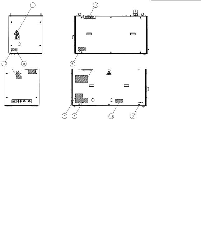
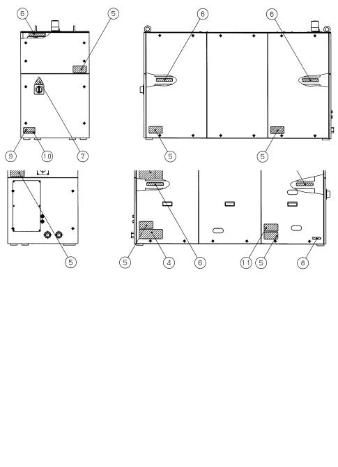
2.4 WARNING LABELS
The oscillator uses high voltages and laser beam radiation. Such hazards are indicated with warning labels attached to the positions shown in Fig.2.4 (a) to (f).
Fig.2.4(a) Warning label positions (C1000-E : front view)
Fig.2.4(b) Warning label positions (C1000-E : rear view)
- 12 -
B-70265EN/01 |
2.SAFETY |
Fig.2.4(c) Warning label positions (C2000-E : front view)
Fig.2.4(d) Warning label positions (C2000-E : rear view)
- 13 -
2.SAFETY |
B-70265EN/01 |
Fig.2.4(e) Warning label positions (C4000-E : front view)
Fig.2.4(f) Warning label positions (C4000-E : rear view)
- 14 -
B-70265EN/01 |
2.SAFETY |
(1) Class indication label (JPN)
|
MAXIMUM OUTPUT |
C1000-E |
2000W |
C2000-E |
5000W |
C4000-E |
8000W |
(1) Class indication label (FDA)
|
MAXIMUM OUTPUT |
C1000-E |
2000W |
C2000-E |
5000W |
C4000-E |
8000W |
- 15 -
2.SAFETY |
B-70265EN/01 |
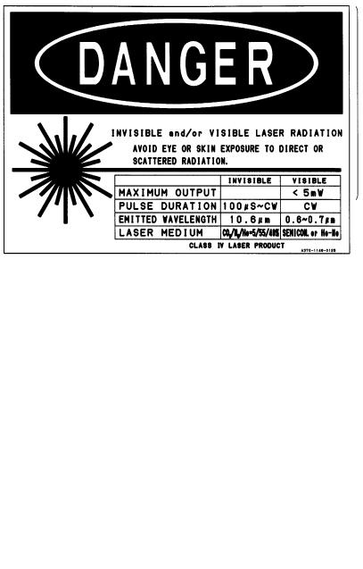
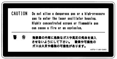
(2) Warning label
(3) Aperture label
(4) Suspension method label
(5) Access panel
- 16 -
B-70265EN/01 |
2.SAFETY |
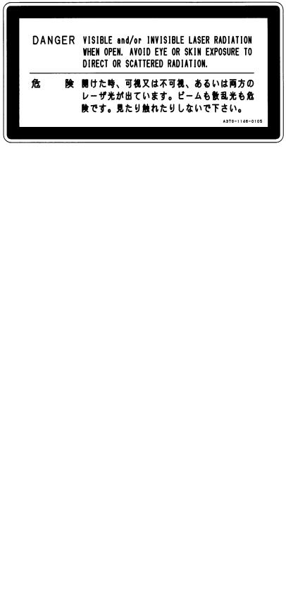
(6)Label inside the access panel
(7)Discharge section label
(8)Certification label
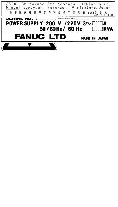
(9)Equipment nameplate
(10) Manufacturer's address label
- 17 -
2.SAFETY |
B-70265EN/01 |
(11)Label for regulating the atmospheric gases in the oscillator housing
- 18 -
B-70265EN/01 |
2.SAFETY |
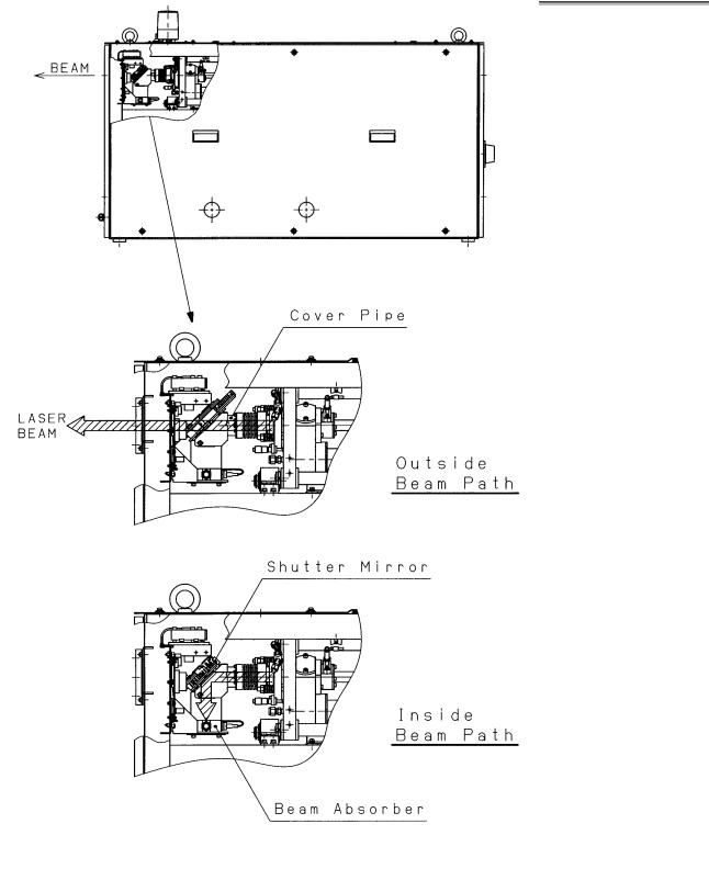
2.5 OPTICAL PATHS IN THE OSCILLATOR
The figures below show the laser optical paths inside the oscillator.
Fig.2.5(a) Optical paths in the C1000-E
- 19 -

2.SAFETY |
B-70265EN/01 |
Fig.2.5(b) Optical paths in the C2000-E
Fig.2.5(c) Optical paths in the C4000-E
- 20 -

B-70265EN/01 |
3.INTERNAL STRUCTURE |
3 INTERNAL STRUCTURE
- 21 -
3.INTERNAL STRUCTURE |
B-70265EN/01 |
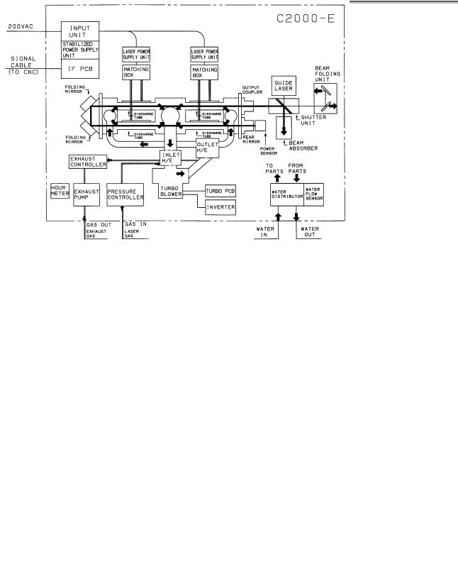
3.1 OUTLINE
Figs.3.1(a) to (c) show the internal structure of the laser oscillator. The oscillator consists of a laser resonator, discharge drive unit, forced gas circulating system, pressure controller, CNC interface, and a protective housing.
Fig.3.1(a) C1000-E internal structure
Fig.3.1(b) C2000-E internal structure
- 22 -
Loading...