


 Loading...
ADDENDUM INSTALLATION MANUAL
System air conditioner
RXYCQ24
RXYCQ28
RXYCQ32
RXYCQ38
RXYCQ40
RXYCQ24
RXYCQ28
RXYCQ32 VRV Classic System air conditioner
RXYCQ38
RXYCQ40
Addendum Installation manual
CONTENTS |
Page |
|
1. |
Introduction................................................................................ |
1 |
|
1.1. Combination................................................................................. |
1 |
|
1.2. Optional accessories ................................................................... |
1 |
2. |
Refrigerant piping ...................................................................... |
1 |
3. |
Leak test and vacuum drying..................................................... |
5 |
4. |
Field wiring ................................................................................ |
5 |
|
4.1. Power circuit and cable requirements .......................................... |
5 |
|
4.2. System examples5 |
|
|
4.3. Field line connection: transmission wiring and |
|
|
cool/heat selection ....................................................................... |
6 |
5. |
Additional refrigerant charge ..................................................... |
6 |
6. |
Before operation ........................................................................ |
7 |
|
6.1. Field setting ................................................................................. |
7 |
1.INTRODUCTION
This manual contains additional instructions for the installation of a VRV Classic multiple outdoor unit system. For general instructions regarding the installation of the outdoor units, refer to the VRV classic installation manual.
1.1.Combination
Refer to chapter "1.1.Combination" of the installation manual.
1.2.Optional accessories
Refer to chapter "1.3.Optional accessories" of the installation manual.
■Refrigerant branching kit (for R410A only: Always use an appropriate kit dedicated for your system.)
Refnet header |
|
Refnet joint |
KHRQ22M29H |
|
KHRQ22M20T |
|
|
|
KHRQ22M64H |
|
KHRQ22M29T9 |
|
|
|
KHRQ22M75H |
|
KHRQ22M64T |
|
|
|
|
|
KHRQ22M75T |
|
|
|
■Outdoor unit multi connection piping kit (For R410A only: Always use an appropriate kit dedicated for your system.)
Number of outdoor units connected
2
BHFQ22P1007
■Pipe size reducer (For R410A only: Always use an appropriate kit dedicated for your system.)
RXYCQ22~40
KHRQ22M75T |
KHRQ22M75H |
|
|
2.REFRIGERANT PIPING
■Total capacity/quantity of indoor units
|
|
|
|
|
|
|
Total capacity of indoor |
|
Standard combination of outdoor units |
units |
|||||
|
RXYCQ24 |
= |
RXYCQ10 |
+ |
RXYCQ14 |
300~670 |
|
|
RXYCQ28 |
= |
RXYCQ10 |
+ |
RXYCQ18 |
350~790 |
|
|
RXYCQ32 |
= |
RXYCQ14 |
+ |
RXYCQ18 |
400~960 |
|
|
RXYCQ38 |
= |
RXYCQ18 |
+ |
RXYCQ20 |
475~1140 |
|
|
RXYCQ40 |
= |
RXYCQ20 |
+ |
RXYCQ20 |
500~1200 |
|
|
|
|
|
|
|||
NOTE |
■ |
There are restrictions on |
the refrigerant pipe |
||||
connection order between outdoor units during installation in case of a multiple outdoor unit system.
Install according to the following restrictions.
The capacities of outdoor units A and B must fulfill the following restriction conditions: A≥B.
■For RXYCQ Multi only 2 outside units can be connected.
A B
1 2
1To indoor units
2Outdoor unit multi connection piping kit (first branch)
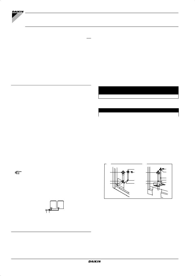
Refer to chapter "6.Refrigerant piping" of the installation manual.
1Outdoor units installed in a multiple outdoor unit system: RXCYQ24~40
■Front connection:
Remove the stop valve cover to connect (A).
■Bottom connection:
Remove the knock holes on the bottom frame and route the piping under the bottom frame (B).
A |
|
B |
|
|
2 |
|
3 |
1 |
3 |
1 |
2 |
|
|
|
8 |
8 |
8 |
8 |
7 |
4 |
6 |
5 |
8 |
|
1.1Precautions when connecting piping between outdoor units (multiple outdoor unit system)
■The 8 Hp unit type can not be used as an independent unit in a multi system.
■To connect the piping between outdoor units, an optional multi connection piping kit BHFQ22P1007 is always required. When installing the piping, follow the instructions in the installation manual that comes with the kit.
■Only proceed with piping work after considering the limitations on installing listed in the RXYCQ installation manual, always referring to the installation manual delivered with the kit.
Addendum Installation manual |
RXYCQ24~40 |
1 |
VRV Classic System air conditioner |
4P378497-1 – 2014.07 |

1.2Possible installation patterns and configurations
■The piping between the outdoor units must be routed level or slightly upward to avoid the risk of oil retention into the piping side.
Pattern 1
1
1
1 To indoor unit
Pattern 2
1 


1
1 To indoor unit
Prohibited patterns: change to pattern 1 or 2.
1 
1
2 |
2 |
1To indoor unit
2Piping between outdoor units
■To avoid the risk of oil retention to the outmost outdoor unit, always connect the stop valve and the piping between outdoor units as shown in the 4 correct possibilities of the figure below.
Prohibited patterns: change to pattern 1 or 2.
1 |
|
1 |
|
2 |
2 |
2 |
2 |
1To indoor unit
2Oil collects to the outmost outdoor unit.
Change to configuration as in figures below
Correct configuration
<![if ! IE]><![endif]>≥200 mm
1 |
1 |
1To indoor unit
■If the piping length between the outdoor units exceeds 2 m, create a rise of 200 mm or more in the gas line within a length of 2 m from the kit.
- If ≤2 m
1 |
|
|
|
|
≤2 m |
|
2 |
|
|||
|
|
|
|||
1To indoor unit
2Piping between outdoor units
-If ≥2 m
<![if ! IE]><![endif]>≥200 mm
1 |
|
|
|
≤2 m |
|
|
|
|
|
|
|
|
|
|
|
|
|
||
|
2 |
|
|
|
|
|
|||
|
|
≥2 m |
|||||||
|
|
|
|
||||||
1To indoor unit
2Piping between outdoor units
1 |
1 |
2 |
2 |
1To indoor unit
2Oil collects to the outmost outdoor unit when the system stops.
RXYCQ24~40 |
Addendum Installation manual |
VRV Classic System air conditioner |
2 |
4P378497-1 – 2014.07 |
<![endif]>manual Installation Addendum 3
<![if ! IE]><![endif]>RXYCQ24~40 conditioner air System Classic VRV 07.2014 – 1-4P378497
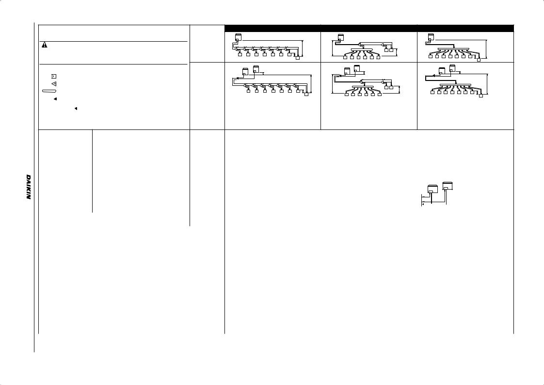
Example of connection |
|
|
|
|
Branch with refnet joint |
|
Branch with refnet joint and refnet header |
|
|
Branch with refnet header |
<![if ! IE]> <![endif]>.2 |
|||||||||||||||||||
|
|
|
|
|
|
|
<![if ! IE]> <![endif]>.1 |
|||||||||||||||||||||||
(Connection of 8 indoor units Heat pump system) |
One outdoor unit |
|
|
|
|
|
|
|
|
|
|
|
|
|
|
|
|
|
|
|
|
|
|
|
|
|
|
|
||
|
|
|
|
|
|
|
|
|
|
|
|
|
|
|
|
|
|
|
|
|
|
|
|
|
|
|
|
|
|
|
• Use the outdoor unit multi connection piping kit that is sold separately as an option |
installed |
|
|
|
|
|
|
|
|
|
|
a |
|
|
|
i |
|
|
|
a |
|
|
|
|
|
|
|
|
<![if ! IE]> <![endif]>Example |
|
(RXYCQ8~20) |
|
|
|
|
|
|
g |
|
|
|
|
A |
|
|
B |
|
|
|
|
|
|
|
|
|
|
|||||
a |
b |
c |
d |
e |
f |
|
|
H1 |
|
|
|
|
k |
|
|
|
|
|
|
|
|
|
|
|||||||
(BHFQ22P1007) for the multi installation of outdoor units. Selection method is as |
|
|
|
|
H1 |
|
|
b |
|
j |
|
|
|
|
|
|
|
|
|
|
|
|||||||||
|
A |
B |
|
C |
D |
E |
F |
G |
|
|
|
|
|
|
|
|
|
|
|
|
|
|
|
H1 |
|
|||||
shown in the right table. |
|
h |
i |
|
j |
k |
l |
m |
n |
|
p |
|
|
|
|
|
7 |
8 |
|
|
|
|
|
|
|
|
|
|
||
|
|
|
|
c |
d |
e |
f |
g |
h |
H2 |
b |
c |
d |
e |
f |
g |
|
h |
|
i |
|
|||||||||
• Do not use the outdoor unit multi connection piping kit (BHFQ22M909+1359) that |
|
|
1 |
2 |
3 |
4 |
5 |
6 |
7 H2 |
|
|
|
|
|
||||||||||||||||
|
|
|
|
|
|
|
|
|
8 |
|
1 |
2 |
3 |
4 |
5 |
6 |
|
1 |
2 |
3 |
4 |
5 |
6 |
7 |
H2 |
|
|
|||
are sold separately as an option of the M-type series and do not use T-joints. |
|
|
|
|
|
|
|
|
|
|
|
|
|
|
|
|
|
|
|
|
8 |
|
||||||||
|
|
|
|
|
|
|
|
|
|
|
|
|
|
|
|
|
|
|
|
|
|
|
|
|
|
|
|
|||
|
|
|
|
|
|
|
|
|
|
|
|
|
|
|
|
|
|
|
|
|
|
|
|
|
|
|
|
|
||
|
|
Outdoor units |
|
|
|
|
|
|
|
|
|
|
|
|
|
|
|
|
|
|
|
|
|
|
|
|
|
|
|
<![if ! IE]> <![endif]>of |
|
|
installed in a |
|
|
|
|
H3 |
|
|
|
|
|
|
|
|
H3 |
|
|
|
|
|
|
|
|
H3 |
|
|
|
|
|
indoor unit |
multiple outdoor |
|
|
|
|
|
|
|
|
|
|
|
|
|
|
|
|
|
|
|
|
|
|
|
|
|||||
|
|
|
|
|
|
|
|
|
|
|
|
|
|
|
i |
|
|
|
|
|
|
|
|
|
|
|
<![if ! IE]> <![endif]>connection |
|||
|
|
unit system |
|
|
|
|
|
|
|
|
|
H1 |
a |
|
|
|
|
|
|
|
a |
|
|
|
|
|
|
|
||
refnet joint |
a |
|
b |
c |
d |
e |
f |
|
g |
|
|
A |
|
B |
|
|
|
|
|
|
|
|
|
|
|
|
||||
(RXYCQ24~40) |
A |
F |
p |
H1 |
|
|
|
k |
|
|
|
|
|
|
|
|
|
H1 |
|
|||||||||||
|
|
B |
C |
D |
E |
G |
|
|
b |
|
j |
|
|
|
|
|
|
|
|
|
|
|||||||||
|
|
|
|
h |
|
i |
j |
k |
l |
m |
n |
|
|
|
|
|
|
7 |
8 |
|
|
|
|
|
|
|
|
|
|
|
refnet header |
|
|
|
|
|
|
|
|
|
|
H2 |
b |
c |
d |
e |
f |
g |
|
|
h |
i |
|
||||||||
|
|
|
1 |
2 |
3 |
4 |
5 |
6 |
7 |
H2 |
c |
d |
e |
f |
g |
h |
|
|
|
|||||||||||
|
|
|
|
1 |
2 |
3 |
4 |
5 |
6 |
|
7 |
H2 |
|
|
||||||||||||||||
outdoor multi connection piping kit |
|
|
|
|
|
|
|
|
|
|
8 |
1 |
2 |
3 |
4 |
5 |
6 |
|
|
|
|
|
|
|
|
|
|
8 |
|
|
|
|
|
|
|
|
|
|
|
|
|
|
|
|
|
|
|
|
|
|
|
|
|
|
|
|
|
|
|||
|
|
|
|
|
|
|
|
|
|
|
|
|
|
|
|
|
|
|
|
|
|
|
|
|
|
|
|
|
||
Install the joint part ( |
part in the figure) of the outdoor unit multi connection piping kit |
|
|
|
|
|
|
|
|
|
|
|
|
|
|
|
|
|
|
|
|
|
|
|
|
|
|
|
|
|
horizontally with attention to the installation restrictions described in "connecting the |
|
|
|
|
|
|
|
|
|
|
|
|
|
|
|
|
|
|
|
|
|
|
|
|
|
|
|
|
|
|
refrigerant piping". |
|
|
|
|
|
|
|
|
|
|
|
|
|
|
|
|
|
|
|
|
|
|
|
|
|
|
|
|
|
|
(*) If the system capacity is 24 or more, re-read to the first outdoor branch as seen from |
|
|
|
|
|
|
|
|
|
|
|
|
|
|
|
|
|
|
|
|
|
|
|
|
|
|
|
|
|
|
the indoor unit. |
|
|
|
|
|
|
|
|
|
|
|
|
|
|
|
|
|
|
|
|
|
|
|
|
|
|
|
|
|
|
|
|
Actual pipe length |
Pipe length between outdoor(*) and indoor units ≤135 m |
|
|
|
|
|
|
|
|
|
|||
|
|
[Example] unit 8: a+b+c+d+e+f+g+p≤135 m |
[Example] unit 6: a+b+h≤135 m, unit 8: a+i+k≤135 m |
[Example] unit 8: a+i≤135 m |
|||||||||||
|
|
|
|||||||||||||
|
|
|
|
|
|
|
|
|
|
|
|
|
|||
|
Between outdoor and indoor units |
Equivalent length |
Equivalent pipe length between outdoor(*) and indoor units ≤155 m (Assume equivalent pipe length of refnet joint to be 0.5 m and of the refnet header to be 1.0 m. (for |
||||||||||||
|
calculation purposes)) |
|
|
|
|
|
|
|
|
|
|
||||
|
|
|
|
|
|
|
|
|
|
|
|
||||
Maximum allowable length |
|
|
|
|
|
|
|
|
|
|
|
|
|||
|
|
Total extension |
Total piping length from outdoor unit* to all indoor units ≤300 m |
|
|
|
|
|
|
|
|||||
|
|
length |
|
|
|
|
|
|
|
||||||
|
|
|
|
|
|
|
|
|
|
|
|
|
|
||
|
|
|
|
|
|
|
|
|
|
|
|
|
|
|
|
|
Between outdoor branch and outdoor unit (Only for |
Actual pipe length Piping length from outdoor branch to outdoor unit ≤10 m. Approximate length: max. 13 m |
|
|
|
|
|
||||||||
|
RXYCQ24 or more) |
|
|
|
|
|
|||||||||
|
|
|
|
|
|
|
|
|
|
|
|
|
|
||
|
|
|
|
|
|
|
|
|
|
|
|
|
|
|
|
|
Between outdoor and indoor units |
Difference in |
Difference in height between outdoor and indoor units (H1)≤30 m. |
|
|
|
|
|
r≤10 m (Approximate length: |
||||||
|
|
|
|
|
|
||||||||||
|
height |
|
|
|
|
|
|||||||||
|
|
|
|
|
|
|
|
|
|
|
|
max. 13 m) |
|||
Allowable height |
Between indoor and indoor units |
Difference in |
Difference in height between adjacent indoor units (H2)≤15 m |
|
|
|
|
|
t≤10 m (Approximate length: |
||||||
height |
|
|
|
r |
t |
max: 13 m) |
|||||||||
|
|
|
|
|
|
|
|
|
|
|
|||||
|
|
|
|
|
|
|
|
|
|
|
|
|
|
|
|
|
Between outdoor and outdoor units |
Difference in |
Difference in height between outdoor unit (main) and outdoor unit (sub) (H3)≤5 m |
|
|
|
|
|
|
|
|||||
|
height |
|
|
|
|
|
|
|
|||||||
|
|
|
|
|
|
|
|
|
|
|
|
|
|
||
|
|
|
|
|
|
|
|
|
|
|
|
|
|||
Allowable length after the branch |
Actual pipe length |
Pipe length from first refrigerant branch kit (either refnet joint or refnet header) to indoor unit ≤40 m (See note 1 on next page) |
|
|
|||||||||||
|
|
|
|
|
|
|
|
|
|
|
|
||||
[Example] unit 8: b+c+d+e+f+g+p≤40 m |
[Example] unit 6: b+h≤40 m, unit 8: i+k≤40 m |
[Example] unit 8: i≤40 m |
|||||||||||||
|
|
|
|||||||||||||
|
|
|
|
|
|
|
|
|
|
|
|
|
|
|
|
Refrigerant branch kit selection |
|
How to select the refnet joint |
|
|
|
How to select the refnet header |
|
|
|
||||||
|
|
|
|
• When using refnet joints at the first branch counted from the outdoor unit side. |
|
• Choose from the following table in accordance with the total capacity of all the indoor |
|||||||||
Refrigerant branch kits can only be used with R410A. |
|
|
Choose from the following table in accordance with the capacity of the outdoor unit. |
|
units connected below the refnet header. |
|
|
||||||||
|
|
|
|
|
|
|
|
|
• Note: 250 type cannot be connected below the refnet header. |
||||||
|
|
|
|
Outdoor unit capacity type |
Refrigerant branch kit name |
|
|
|
|
|
|
|
|
||
|
|
|
|
|
|
Indoor capacity type |
|
|
Refrigerant branch kit name |
|
|||||
|
|
|
|
RXYCQ8 |
KHRQ22M20T |
|
|
|
<290 |
|
|
KHRQ22M29H (Max. 8 branch) |
|
||
|
|
|
|
RXYCQ10~12 |
KHRQ22M29T9 |
|
|
|
|
|
|
||||
|
|
|
|
|
|
|
|
|
|
|
|
|
|||
|
|
|
|
|
|
|
290≤x<640 |
|
|
KHRQ22M64H (Max. 8 branch)(a) |
|
||||
|
|
|
|
RXYCQ14~20, 24 |
KHRQ22M64T |
|
|
|
|
|
|
||||
|
|
|
|
|
|
|
≥640 |
|
|
KHRQ22M75H (Max. 8 branch) |
|
||||
|
|
|
|
RXYCQ28, 32, 38, 40 |
KHRQ22M75T |
|
|
|
|
|
|
||||
|
|
|
|
|
|
|
(a) See note 2 on next page |
|
|
|
|||||
|
|
|
|
|
|
|
|
|
|
|
|
||||
|
|
|
|
• For refnet joints other than the first branch, select the proper branch kit model based on |
How to choose an outdoor multi connection piping kit (needed if the outdoor |
||||||||||
|
|
|
|
the total capacity index. |
|
|
|
unit capacity type is RXYCQ24 or more.) |
|
|
|||||
|
|
|
|
|
|
|
|
|
• Choose from the following table in accordance with the number of outdoor units. |
||||||
|
|
|
|
Indoor capacity type |
Refrigerant branch kit name |
|
|||||||||
|
|
|
|
|
|
|
|
|
|
|
|
||||
|
|
|
|
<200 |
KHRQ22M20T |
|
|
|
Number of outdoor units |
Branch kit name |
|
||||
|
|
|
|
|
|
|
|
|
2 |
|
|
BHFQ22P1007 |
|
||
|
|
|
|
200≤x<290 |
KHRQ22M29T9 |
|
|
|
|
||||||
|
|
|
|
|
|
|
|
|
|
|
|
|
|||
|
|
|
|
|
|
|
|
|
|
|
|
|
|
|
|
|
|
|
|
290≤x<640 |
KHRQ22M64T |
|
|
|
|
|
|
|
|
|
|
|
|
|
|
|
|
|
|
|
|
|
|
|
|
|
|
|
|
|
|
≥640 |
KHRQ22M75T |
|
|
|
|
|
|
|
|
|
|
|
|
|
|
|
|
|
|
|
|
|
|
|
|
|
|
|
|
|
|
|
|
|
|
|
|
|
|
|
|
|
|
|
|
|
[Example] |
|
[Example] |
|
|
[Example] |
|
|
|
||||
|
Example of downstream indoor units |
|
in case of refnet joint C; indoor units 3+4+5+6+7+8 |
in case of refnet joint B; indoor units 7+8, |
in case of refnet header; |
||||||||||
|
|
|
|
|
|
in case of refnet header; indoor units 1+2+3+4+5+6 |
indoor units 1+2+3+4+5+6+7+8 |
||||||||
|
|
|
|
|
|
|
|
|
|
|
|
|
|
|
|
Loading...