


 Loading...
Installer reference guide
Split system air conditioners
RZQG71L9V1L |
|
|
RZQG71L8Y1L |
|
|
RZQG100L8Y1L |
Installer reference guide |
|
RZQG125L8Y1L |
English |
|
RZQG140L7Y1L |
Split system air conditioners |
|

Table of contents
Table of contents
1 General safety precautions |
2 |
||
1.1 |
About the documentation .......................................................... |
2 |
|
|
1.1.1 Meaning of warnings and symbols.............................. |
3 |
|
1.2 |
For the installer.......................................................................... |
3 |
|
|
1.2.1 |
General ....................................................................... |
3 |
|
1.2.2 |
Installation site ............................................................ |
3 |
|
1.2.3 |
Refrigerant .................................................................. |
4 |
|
1.2.4 |
Brine............................................................................ |
4 |
|
1.2.5 |
Water .......................................................................... |
4 |
|
1.2.6 |
Electrical ..................................................................... |
5 |
2 |
About the documentation |
5 |
||
|
2.1 |
About this document.................................................................. |
5 |
|
|
2.2 |
Installer reference guide at a glance ......................................... |
6 |
|
3 |
About the box |
6 |
||
|
3.1 |
Overview: About the box ........................................................... |
6 |
|
|
3.2 |
Outdoor unit............................................................................... |
6 |
|
|
|
3.2.1 |
To unpack the outdoor unit ......................................... |
6 |
|
|
3.2.2 |
To handle the outdoor unit .......................................... |
6 |
|
|
3.2.3 |
To remove the accessories from the outdoor unit....... |
7 |
4 About the units and options |
7 |
|||
|
4.1 |
Overview: About the units and options...................................... |
7 |
|
|
4.2 |
Identification .............................................................................. |
7 |
|
|
|
4.2.1 |
Identification label: Outdoor unit ................................. |
7 |
|
4.3 |
Combining units and options ..................................................... |
7 |
|
|
|
4.3.1 |
Possible options for the outdoor unit........................... |
7 |
5 |
Preparation |
7 |
||
|
5.1 |
Overview: Preparation............................................................... |
7 |
|
|
5.2 |
Preparing installation site .......................................................... |
7 |
|
|
|
5.2.1 |
Installation site requirements of the outdoor unit ........ |
7 |
|
|
5.2.2 |
Additional installation site requirements of the |
|
|
|
|
outdoor unit in cold climates ....................................... |
8 |
|
5.3 |
Preparing refrigerant piping....................................................... |
8 |
|
|
|
5.3.1 |
About reusing existing piping ...................................... |
8 |
|
|
5.3.2 |
Refrigerant piping requirements.................................. |
9 |
|
|
5.3.3 |
Refrigerant piping insulation ....................................... |
10 |
|
5.4 |
Preparing electrical wiring ......................................................... |
10 |
|
|
|
5.4.1 |
About preparing electrical wiring................................. |
10 |
|
6.5.2 |
Precautions when checking the refrigerant piping ....... |
15 |
|
6.5.3 |
Checking refrigerant piping: Setup............................... |
16 |
|
6.5.4 |
To check for leaks........................................................ |
16 |
|
6.5.5 |
To perform vacuum drying ........................................... |
16 |
6.6 |
Charging refrigerant ................................................................... |
16 |
|
|
6.6.1 |
About charging refrigerant ........................................... |
16 |
|
6.6.2 |
Precautions when charging refrigerant ........................ |
17 |
|
6.6.3 |
To determine the additional refrigerant amount ........... |
17 |
|
6.6.4 |
To determine the complete recharge amount .............. |
17 |
|
6.6.5 |
Charging refrigerant: Setup.......................................... |
18 |
|
6.6.6 |
To charge refrigerant ................................................... |
18 |
|
6.6.7 |
To fix the fluorinated greenhouse gases label ............. |
18 |
6.7 |
Connecting the electrical wiring.................................................. |
18 |
|
|
6.7.1 |
About connecting the electrical wiring.......................... |
18 |
|
6.7.2 |
About electrical compliance ......................................... |
18 |
|
6.7.3 |
Precautions when connecting the electrical wiring ...... |
18 |
|
6.7.4 |
Guidelines when connecting the electrical wiring ........ |
19 |
|
6.7.5 |
Specifications of standard wiring components............. |
19 |
|
6.7.6 |
To connect the electrical wiring on the outdoor unit..... |
19 |
6.8 |
Finishing the outdoor unit installation ......................................... |
20 |
|
|
6.8.1 |
To finish the outdoor unit installation ........................... |
20 |
|
6.8.2 |
To close the outdoor unit ............................................. |
20 |
6.8.3To check the insulation resistance of the compressor . 21
7 |
Commissioning |
21 |
|
|
7.1 |
Overview: Commissioning.......................................................... |
21 |
|
7.2 |
Precautions when commissioning .............................................. |
21 |
|
7.3 |
Checklist before commissioning................................................. |
21 |
|
7.4 |
To perform a test run.................................................................. |
22 |
|
7.5 |
Error codes when performing a test run ..................................... |
22 |
8 |
Hand-over to the user |
23 |
|
9 |
Maintenance and service |
23 |
|
|
9.1 |
Overview: Maintenance and service .......................................... |
23 |
|
9.2 |
Maintenance safety precautions................................................. |
23 |
|
9.3 |
Checklist for yearly maintenance of the outdoor unit ................. |
23 |
10 |
Troubleshooting |
23 |
|
|
10.1 |
Overview: Troubleshooting......................................................... |
23 |
|
10.2 |
Precautions when troubleshooting ............................................. |
23 |
11 |
Disposal |
24 |
|
|
11.1 |
Overview: Disposal..................................................................... |
24 |
|
11.2 |
About pump down ...................................................................... |
24 |
|
11.3 |
To pump down............................................................................ |
24 |
6 Installation |
10 |
12 Technical data |
25 |
6.1 |
Overview: Installation ................................................................ |
10 |
||
6.2 |
Opening the units ...................................................................... |
10 |
||
|
|
6.2.1 |
About opening the units .............................................. |
10 |
|
|
6.2.2 |
To open the outdoor unit............................................. |
10 |
6.3 |
Mounting the outdoor unit.......................................................... |
11 |
||
|
|
6.3.1 |
About mounting the outdoor unit................................. |
11 |
|
|
6.3.2 |
Precautions when mounting the outdoor unit.............. |
11 |
|
|
6.3.3 |
To provide the installation structure ............................ |
11 |
|
|
6.3.4 |
To install the outdoor unit............................................ |
11 |
|
|
6.3.5 |
To provide drainage .................................................... |
11 |
|
|
6.3.6 |
To prevent the outdoor unit from falling over .............. |
12 |
6.4 |
Connecting the refrigerant piping .............................................. |
12 |
||
|
|
6.4.1 |
About connecting the refrigerant piping ...................... |
12 |
|
|
6.4.2 |
Precautions when connecting the refrigerant piping ... |
12 |
|
|
6.4.3 |
Guidelines when connecting the refrigerant piping ..... |
13 |
|
|
6.4.4 |
Pipe bending guidelines.............................................. |
13 |
|
|
6.4.5 |
To flare the pipe end ................................................... |
13 |
|
|
6.4.6 |
To braze the pipe end ................................................. |
13 |
|
|
6.4.7 |
Using the stop valve and service port ......................... |
13 |
|
|
6.4.8 |
To connect the refrigerant piping to the outdoor unit .. |
14 |
|
|
6.4.9 |
To determine if oil traps are required |
15 |
|
|
|||
|
6.5 |
Checking the refrigerant piping ................................................. |
15 |
|
|
|
6.5.1 |
About checking the refrigerant piping ......................... |
15 |
|
|
|
|
|
12.1 |
Service space: Outdoor unit ....................................................... |
25 |
12.2 |
Piping diagram: Outdoor unit...................................................... |
26 |
12.3 |
Wiring diagram: Outdoor unit ..................................................... |
27 |
13 Glossary |
28 |
|
1 General safety precautions
1.1About the documentation
▪The original documentation is written in English. All other languages are translations.
▪The precautions described in this document cover very important topics, follow them carefully.
▪The installation of the system, and all activities described in the installation manual and the installer reference guide must be performed by an authorized installer.
Installer reference guide |
RZQG71L9V1L + RZQG71~125L8Y1L + RZQG140L7Y1L |
2 |
Split system air conditioners |
4P473074-1 – 2017.03 |
1 General safety precautions
1.1.1Meaning of warnings and symbols
DANGER
Indicates a situation that results in death or serious injury.
DANGER: RISK OF ELECTROCUTION
Indicates a situation that could result in electrocution.
DANGER: RISK OF BURNING
Indicates a situation that could result in burning because of extreme hot or cold temperatures.
DANGER: RISK OF EXPLOSION
Indicates a situation that could result in explosion.
WARNING
Indicates a situation that could result in death or serious injury.
WARNING: FLAMMABLE MATERIAL
CAUTION
Indicates a situation that could result in minor or moderate injury.
WARNING
Tear apart and throw away plastic packaging bags so that nobody, especially children, can play with them. Possible risk: suffocation.
DANGER: RISK OF BURNING
▪Do NOT touch the refrigerant piping, water piping or internal parts during and immediately after operation. It could be too hot or too cold. Give it time to return to normal temperature. If you must touch it, wear protective gloves.
▪Do NOT touch any accidental leaking refrigerant.
WARNING
Provide adequate measures to prevent that the unit can be used as a shelter by small animals. Small animals that make contact with electrical parts can cause malfunctions, smoke or fire.
CAUTION
Do NOT touch the air inlet or aluminium fins of the unit.
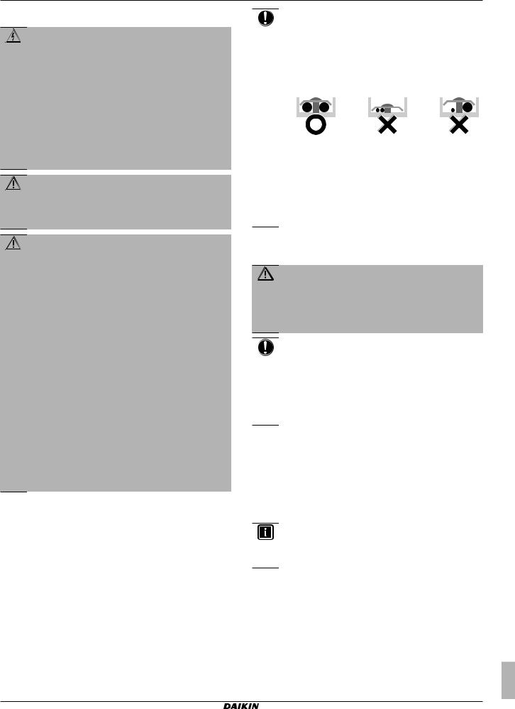
NOTICE
▪Do NOT place any objects or equipment on top of the unit.
NOTICE
Indicates a situation that could result in equipment or property damage.
INFORMATION
Indicates useful tips or additional information.
Symbol |
Explanation |
Before installation, read the installation and operation manual, and the wiring instruction sheet.
Before performing maintenance and service tasks, read the service manual.
For more information, see the installer and user reference guide.
1.2For the installer
1.2.1General
If you are not sure how to install or operate the unit, contact your dealer.
NOTICE
Improper installation or attachment of equipment or accessories could result in electric shock, short-circuit, leaks, fire or other damage to the equipment. Only use accessories, optional equipment and spare parts made or approved by Daikin.
▪ Do NOT sit, climb or stand on the unit.
NOTICE
Works executed on the outdoor unit are best done under dry weather conditions to avoid water ingress.
In accordance with the applicable legislation, it might be necessary to provide a logbook with the product containing at least: information on maintenance, repair work, results of tests, stand-by periods,…
Also, at least, following information must be provided at an accessible place at the product:
▪Instructions for shutting down the system in case of an emergency
▪Name and address of fire department, police and hospital
▪Name, address and day and night telephone numbers for obtaining service
In Europe, EN378 provides the necessary guidance for this logbook.
1.2.2Installation site
▪Provide sufficient space around the unit for servicing and air circulation.
▪Make sure the installation site withstands the unit's weight and vibration.
▪Make sure the area is well ventilated. Do NOT block any ventilation openings.
▪Make sure the unit is level.
Do NOT install the unit in the following places:
WARNING
Make sure installation, testing and applied materials comply with applicable legislation (on top of the instructions described in the Daikin documentation).
CAUTION
Wear adequate personal protective equipment (protective gloves, safety glasses,…) when installing, maintaining or servicing the system.
▪In potentially explosive atmospheres.
▪In places where there is machinery that emits electromagnetic waves. Electromagnetic waves may disturb the control system, and cause malfunction of the equipment.
▪In places where there is a risk of fire due to the leakage of flammable gases (example: thinner or gasoline), carbon fibre, ignitable dust.
▪In places where corrosive gas (example: sulphurous acid gas) is produced. Corrosion of copper pipes or soldered parts may cause the refrigerant to leak.
RZQG71L9V1L + RZQG71~125L8Y1L + RZQG140L7Y1L |
Installer reference guide |
Split system air conditioners |
3 |
4P473074-1 – 2017.03 |
1 General safety precautions
1.2.3Refrigerant
If applicable. See the installation manual or installer reference guide of your application for more information.
NOTICE
Make sure refrigerant piping installation complies with applicable legislation. In Europe, EN378 is the applicable standard.
NOTICE
Make sure the field piping and connections are not subjected to stress.
WARNING
During tests, NEVER pressurize the product with a pressure higher than the maximum allowable pressure (as indicated on the nameplate of the unit).
WARNING
Take sufficient precautions in case of refrigerant leakage. If refrigerant gas leaks, ventilate the area immediately. Possible risks:
▪Excessive refrigerant concentrations in a closed room can lead to oxygen deficiency.
▪Toxic gas may be produced if refrigerant gas comes into contact with fire.
DANGER: RISK OF EXPLOSION
Pump down – Refrigerant leakage. If you want to pump down the system, and there is a leakage in the refrigerant circuit:
▪Do NOT use the unit's automatic pump down function, with which you can collect all refrigerant from the system into the outdoor unit. Possible consequence:
Self-combustion and explosion of the compressor because of air going into the operating compressor.
▪Use a separate recovery system so that the unit's compressor does NOT have to operate.
WARNING
Always recover the refrigerant. Do NOT release them directly into the environment. Use a vacuum pump to evacuate the installation.
NOTICE
After all the piping has been connected, make sure there is no gas leak. Use nitrogen to perform a gas leak detection.
NOTICE
▪To avoid compressor breakdown, do NOT charge more than the specified amount of refrigerant.
▪When the refrigerant system is to be opened, refrigerant must be treated according to the applicable legislation.
▪Only use tools exclusively for the refrigerant type used in the system, this to ensure pressure resistance and prevent foreign materials from entering into the system.
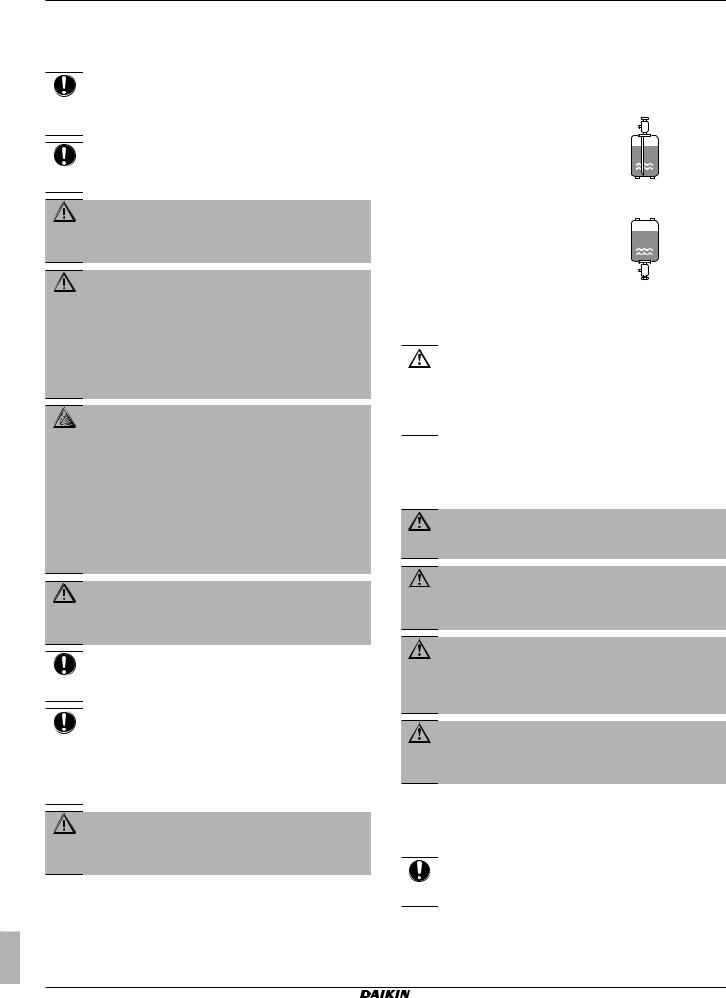
▪Charge the liquid refrigerant as follows:
If |
Then |
||
A siphon tube is present |
Charge with the cylinder upright. |
||
(i.e., the cylinder is marked with |
|
|
|
"Liquid filling siphon attached") |
|
|
|
|
|
|
|
|
|
||
A siphon tube is NOT present |
Charge with the cylinder upside |
||
|
down. |
||
|
|
|
|
|
|
|
|
▪Open refrigerant cylinders slowly.
▪Charge the refrigerant in liquid form. Adding it in gas form may prevent normal operation.
CAUTION
When the refrigerant charging procedure is done or when pausing, close the valve of the refrigerant tank immediately. If the valve is not closed immediately, remaining pressure might charge additional refrigerant.
Possible consequence: Incorrect refrigerant amount.
1.2.4Brine
If applicable. See the installation manual or installer reference guide of your application for more information.
WARNING
The selection of the brine MUST be in accordance with the applicable legislation.
WARNING
Take sufficient precautions in case of brine leakage. If brine leaks, ventilate the area immediately and contact your local dealer.
WARNING
The ambient temperature inside the unit can get much higher than that of the room, e.g. 70°C. In case of a brine leak, hot parts inside the unit can create a hazardous situation.
WARNING
The use and installation of the application MUST comply with the safety and environmental precautions specified in the applicable legislation.
1.2.5Water
WARNING
Make sure there is no oxygen in the system. Refrigerant may only be charged after performing the leak test and the vacuum drying.
▪In case re-charge is required, refer to the nameplate of the unit. It states the type of refrigerant and necessary amount.
▪The unit is factory charged with refrigerant and depending on pipe sizes and pipe lengths some systems require additional charging of refrigerant.
If applicable. See the installation manual or installer reference guide of your application for more information.
NOTICE
Make sure water quality complies with EU directive 98/83 EC.
Installer reference guide |
RZQG71L9V1L + RZQG71~125L8Y1L + RZQG140L7Y1L |
4 |
Split system air conditioners |
4P473074-1 – 2017.03 |
2 About the documentation
1.2.6Electrical
DANGER: RISK OF ELECTROCUTION
▪Turn OFF all power supply before removing the switch box cover, connecting electrical wiring or touching electrical parts.
▪Disconnect the power supply for more than 1 minute, and measure the voltage at the terminals of main circuit capacitors or electrical components before servicing. The voltage MUST be less than 50 V DC before you can touch electrical components. For the location of the terminals, see the wiring diagram.
▪Do NOT touch electrical components with wet hands.
▪Do NOT leave the unit unattended when the service cover is removed.
WARNING
If NOT factory installed, a main switch or other means for disconnection, having a contact separation in all poles providing full disconnection under overvoltage category III condition, MUST be installed in the fixed wiring.
WARNING
▪ONLY use copper wires.
▪Make sure the field wiring complies with the applicable legislation.
▪All field wiring must be performed in accordance with the wiring diagram supplied with the product.
▪NEVER squeeze bundled cables and make sure they do not come in contact with the piping and sharp edges. Make sure no external pressure is applied to the terminal connections.
▪Make sure to install earth wiring. Do NOT earth the unit to a utility pipe, surge absorber, or telephone earth. Incomplete earth may cause electrical shock.
▪Make sure to use a dedicated power circuit. NEVER use a power supply shared by another appliance.
▪Make sure to install the required fuses or circuit breakers.
▪Make sure to install an earth leakage protector. Failure to do so may cause electric shock or fire.
▪When installing the earth leakage protector, make sure it is compatible with the inverter (resistant to high frequency electric noise) to avoid unnecessary opening of the earth leakage protector.
NOTICE
Precautions when laying power wiring:
▪Do not connect wiring of different thicknesses to the power terminal block (slack in the power wiring may cause abnormal heat).
▪When connecting wiring which is the same thickness, do as shown in the figure below.
▪For wiring, use the designated power wire and connect firmly, then secure to prevent outside pressure being exerted on the terminal board.
▪Use an appropriate screwdriver for tightening the terminal screws. A screwdriver with a small head will damage the head and make proper tightening impossible.
▪Over-tightening the terminal screws may break them.
Install power cables at least 1 metre away from televisions or radios to prevent interference. Depending on the radio waves, a distance of 1 metre may not be sufficient.
WARNING
▪After finishing the electrical work, confirm that each electrical component and terminal inside the electrical components box is connected securely.
▪Make sure all covers are closed before starting up the unit.
NOTICE
Only applicable if the power supply is three phase, and the compressor has an ON/OFF starting method.
If there exists the possibility of reversed phase after a momentary black out and the power goes on and off while the product is operating, attach a reversed phase protection circuit locally. Running the product in reversed phase can break the compressor and other parts.
2 About the documentation
2.1About this document
Target audience
Authorised installers
INFORMATION
This appliance is intended to be used by expert or trained users in shops, in light industry and on farms, or for commercial use by lay persons.
Documentation set
This document is part of a documentation set. The complete set consists of:
▪General safety precautions:
▪Safety instructions that you must read before installing
▪Format: Paper (in the box of the outdoor unit)
▪Outdoor unit installation manual:
▪Installation instructions
▪Format: Paper (in the box of the outdoor unit)
RZQG71L9V1L + RZQG71~125L8Y1L + RZQG140L7Y1L |
Installer reference guide |
Split system air conditioners |
5 |
4P473074-1 – 2017.03 |
3 About the box
▪Installer reference guide:
▪ Preparation of the installation, reference data,…
3.2Outdoor unit
▪Format: Digital files on http://www.daikineurope.com/support- and-manuals/product-information/
Latest revisions of the supplied documentation may be available on the regional Daikin website or via your dealer.
The original documentation is written in English. All other languages are translations.
Technical engineering data
▪A subset of the latest technical data is available on the regional Daikin website (publicly accessible).
▪The full set of latest technical data is available on the Daikin extranet (authentication required).
2.2Installer reference guide at a glance
Chapter |
Description |
General safety |
Safety instructions that you must read |
precautions |
before installing |
About the documentation |
What documentation exists for the |
|
installer |
About the box |
How to unpack the units and remove |
|
their accessories |
About the units and |
▪ How to identify the units |
options |
▪ Possible combinations of units and |
|
|
|
options |
|
|
Preparation |
What to do and know before going |
|
on site |
Installation |
What to do and know to install the |
|
system |
Commissioning |
What to do and know to commission the |
|
system after it is installed |
Hand over to the user |
What to give and explain to the user |
Maintenance and service |
How to maintain and service the units |
Troubleshooting |
What to do in case of problems |
|
|
Disposal |
How to dispose of the system |
Technical data |
Specifications of the system |
|
|
Glossary |
Definition of terms |
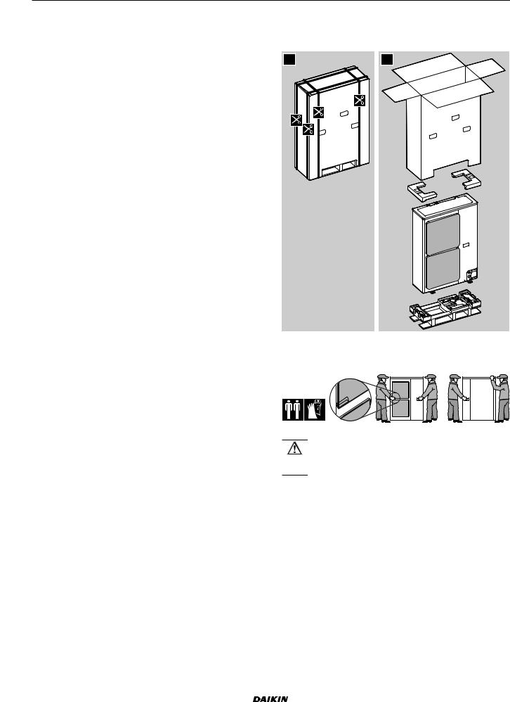
3.2.1To unpack the outdoor unit
1 |
2 |
3.2.2To handle the outdoor unit
Carry the unit slowly as shown:
CAUTION
To avoid injury, do NOT touch the air inlet or aluminium fins of the unit.
3 About the box
3.1Overview: About the box
This chapter describes what you have to do after the box with the outdoor unit is delivered on-site.
It contains information about:
▪Unpacking and handling the units
▪Removing the accessories from the units Keep the following in mind:
▪At delivery, the unit must be checked for damage. Any damage must be reported immediately to the carrier's claims agent.
▪Bring the packed unit as close as possible to its final installation position to prevent damage during transport.
|
|
|
|
|
|
|
|
|
|
Installer reference guide |
RZQG71L9V1L + RZQG71~125L8Y1L + RZQG140L7Y1L |
6 |
Split system air conditioners |
||
4P473074-1 – 2017.03 |
|||
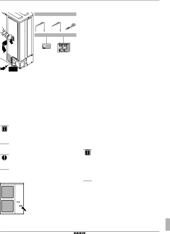
3.2.3To remove the accessories from the outdoor unit
a |
b |
c |
|||
|
1× |
|
1× |
|
2× |
|
|
|
|
|
|
|
|
|
|
|
|
|
|
|
|
|
|
d |
e |
1× |
1× |
2 |
|
3 |
|
ENERG |
ENERG |
1 |
1× |
|
aGeneral safety precautions
bOutdoor unit installation manual
cCable tie
dFluorinated greenhouse gases label
eEnergy label
4 About the units and options
4.1Overview: About the units and options
This chapter contains information about:
▪Identifying the outdoor unit
▪Combining the outdoor unit with options
INFORMATION
For year round cooling applications with low indoor humidity conditions, such as Electronic Data Processing rooms, contact your dealer or see the engineering databook or the service manual.
4.2Identification
NOTICE
When installing or servicing several units at the same time, make sure NOT to switch the service panels between different models.
4.2.1Identification label: Outdoor unit
Location
RZQG71L9V1L + RZQG71~125L8Y1L + RZQG140L7Y1L Split system air conditioners
4P473074-1 – 2017.03
4 About the units and options
4.3Combining units and options
4.3.1Possible options for the outdoor unit
Demand adaptor kit
Can be used for the following:
▪Low noise: To lower the operation sound of the outdoor unit.
▪I-demand function: To limit the power consumption from the system (example: budget control, limit power consumption during peak moments…).
Model |
Demand adaptor kit |
RZQG_Y1 |
KRP58M51 |
|
|
RZQG_V1 |
SB.KRP58M51 |
For installation instructions, see the installation manual of the demand adaptor kit.
5 Preparation
5.1Overview: Preparation
This chapter describes what you have to do and know before going on-site.
It contains information about:
▪Preparing the installation site
▪Preparing the refrigerant piping
▪Preparing the electrical wiring
5.2Preparing installation site
Do NOT install the unit in places often used as work place. In case of construction works (e.g. grinding works) where a lot of dust is created, the unit must be covered.
Choose the installation location with sufficient place for carrying the unit in and out of the site.
5.2.1Installation site requirements of the outdoor unit
INFORMATION
Also read the following requirements:
▪General installation site requirements. See the "General safety precautions" chapter.
▪Service space requirements. See the "Technical data" chapter.
▪Refrigerant piping requirements (length, height difference). See further in this "Preparation" chapter.
▪Select a place where rain can be avoided as much as possible.
▪Take care that in the event of a water leak, water cannot cause any damage to the installation space and surroundings.
▪Choose a location where the hot/cold air discharged from the unit or the operation noise, will NOT disturb anyone.
▪Heat exchanger fins are sharp and injury is possible. Choose an installation location where there is no risk for injury (especially in areas where children play).
Do NOT install the unit in the following places:
Installer reference guide
7

5 Preparation
▪Sound sensitive areas (e.g. near a bedroom), so that the operation noise will cause no trouble.
Note: If the sound is measured under actual installation conditions, the measured value might be higher than the sound pressure level mentioned in Sound spectrum in the data book due to environmental noise and sound reflections.
INFORMATION
The sound pressure level is less than 70 dBA.
▪In places where a mineral oil mist, spray or vapour may be present in the atmosphere. Plastic parts may deteriorate and fall off or cause water leakage.
It is NOT recommended to install the unit in the following places because it may shorten the life of the unit:
▪Where the voltage fluctuates a lot
▪In vehicles or vessels
▪Where acidic or alkaline vapour is present
Seaside installation. Make sure the outdoor unit is NOT directly exposed to sea winds. This is to prevent corrosion caused by high levels of salt in the air, which might shorten the life of the unit.
Install the outdoor unit away from direct sea winds.
Example: Behind the building.
b
a
c
If the outdoor unit is exposed to direct sea winds, install a windbreaker.
▪Height of windbreaker≥1.5×height of outdoor unit
▪Mind the service space requirements when installing the windbreaker.
d c
b
a
d c
aSea wind
bBuilding
cOutdoor unit
dWindbreaker
Strong winds (≥18 km/h) blowing against the outdoor unit’s air outlet causes short circuit (suction of discharge air). This may result in:
▪deterioration of the operational capacity;
▪frequent frost acceleration in heating operation;
▪disruption of operation due to decrease of low pressure or increase of high pressure;
▪a broken fan (if a strong wind blows continuously on the fan, it may start rotating very fast, until it breaks).
It is recommended to install a baffle plate when the air outlet is exposed to wind.
Installer reference guide
8
It is recommended to install the outdoor unit with the air inlet facing the wall and NOT directly exposed to the wind.


 b
b
a
b |
c |
|
aBaffle plate
bPrevailing wind direction
cAir outlet
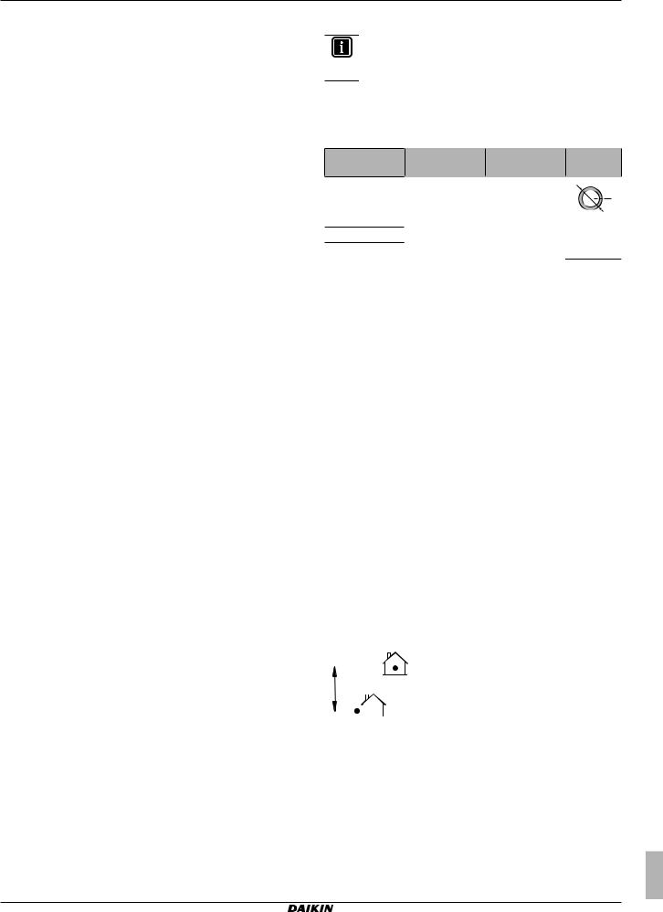
The outdoor unit is designed for outdoor installation only, and for ambient temperatures ranging:
Model |
Cooling |
Heating |
RZQG |
–15~50°C |
–20~15.5°C |
|
|
|
5.2.2Additional installation site requirements of the outdoor unit in cold climates
Protect the outdoor unit against direct snowfall and take care that the
outdoor unit is NEVER snowed up.
a


 c
c
|
d |
c |
b |
|
aSnow cover or shed
bPedestal (minimum height = 150 mm)
cPrevailing wind direction
dAir outlet
5.3Preparing refrigerant piping
5.3.1About reusing existing piping
In some cases you may reuse existing piping, in other cases not.
RZQG71L9V1L + RZQG71~125L8Y1L + RZQG140L7Y1L Split system air conditioners 4P473074-1 – 2017.03
Reuse not allowed
You may not reuse existing piping in the following cases:
▪When the compressor in the old installation had problems (example: breakdown). Possible consequence: oxidised coolant oil, scale residue and other adverse effects.
▪When the indoor and outdoor units were disconnected from the piping for a long time. Possible consequence: water and dirt in the piping.
▪When the copper piping is corroded.
Reuse allowed
In other cases than above, you may reuse existing piping but keep the following in mind:
Item |
Description |
|
Piping diameter |
Must comply with requirements. See |
|
Piping material |
"5.3.2 Refrigerant piping requirements" on |
|
page 9. |
||
|
||
Piping length and |
||
|
||
height difference |
|
|
|
|
|
Piping insulation |
If deteriorated, must be replaced. |
|
|
Must comply with requirements. See |
|
|
"5.3.3 Refrigerant piping insulation" on |
|
|
page 10. |
|
Flare connections |
May not be reused. Make new ones to |
|
|
prevent leaks. See "6.4.3 Guidelines when |
|
|
connecting the refrigerant piping" on |
|
|
page 13 and "6.4.5 To flare the pipe |
|
|
end" on page 13. |
|
Welded connections |
Must be checked for gas leaks. |
|
|
|
|
Cleaning pipes |
If the following conditions are met, you do |
|
|
not have to clean the pipes. Otherwise, you |
|
|
must clean the pipes, or install new ones. |
|
|
Conditions: |
|
|
▪ The total one way piping length is <50 m |
|
|
(i.e. L1<50 m). |
|
|
▪ You pumped down the old system |
|
|
correctly. This means: |
|
|
▪ Operated the unit continuously for |
|
|
30 minutes in cooling mode. |
|
|
▪ Pumped down the system. |
|
|
▪ Removed the old units. |
|
|
▪ Piping is not contaminated (see below). |
|
|
|
To check if piping is contaminated
You must check if existing piping is contaminated because using piping with deteriorated oil will cause compressor breakdown.
Prerequisite: You need an oil checking reference card. This is available from your dealer.
1Put some residual oil from the piping on a piece of white paper.
2Compare the colours:
If the oil colour is… |
Then… |
Identical to or darker than the |
You must clean the existing |
circled colour on the reference |
piping, or install new piping. |
card |
|
Lighter than the circled colour |
You can reuse the piping |
on the reference card |
without cleaning. |
RZQG71L9V1L + RZQG71~125L8Y1L + RZQG140L7Y1L Split system air conditioners
4P473074-1 – 2017.03
5 Preparation
5.3.2Refrigerant piping requirements
INFORMATION
Also read the precautions and requirements in the "General safety precautions" chapter.
Refrigerant piping material
▪Piping material: Phosphoric acid deoxidised seamless copper.
▪Piping temper grade and thickness:
Outer diameter |
Temper grade |
Thickness (t)(a) |
|
(Ø) |
|
|
|
6.4 mm (1/4") |
Annealed (O) |
≥0.8 mm |
Ø |
9.5 mm (3/8") |
|
|
t |
|
|
|
|
12.7 mm (1/2") |
|
|
|
15.9 mm (5/8") |
Annealed (O) |
≥1.0 mm |
|
19.1 mm (3/4") |
Half hard (1/2H) |
|
|
(a)Depending on the applicable legislation and the unit's maximum working pressure (see "PS High" on the unit name plate), larger piping thickness might be required.
▪Flare connections: Only use annealed material.
Refrigerant piping diameter
The refrigerant piping diameters (for L1) must comply with the
following:
Model |
New(a)/ |
L1 liquid |
L1 gas piping |
|
Existing(b) |
piping |
|
RZQG71 |
Size down |
Ø6.4 mm |
Ø12.7 mm |
|
|
|
|
|
Standard |
Ø9.5 mm |
Ø15.9 mm |
|
Size up |
Ø12.7 mm |
— |
RZQG100~140 |
Size down |
Ø6.4 mm |
— |
|
|
|
|
|
Standard |
Ø9.5 mm |
Ø15.9 mm |
|
Size up |
Ø12.7 mm |
Ø19.1 mm |
|
|
|
|
(a)When installing new piping, use the same diameters as the connections on the outdoor units (i.e. standard diameters for liquid and gas piping).
(b)When reusing existing piping, you may use the size up or size down diameters, but then capacity might decrease, and stricter piping length requirements are applicable. Assess these limitations in relation to the complete installation.
Refrigerant piping length and height difference
The piping length and height difference must comply with the
following requirements:
|
|
|
|
|
L1 |
|
|
|
|
|
| <![if ! IE]> <![endif]>H1 |
|
|
|
|
|
|
||||
|
|
|
|
|
|
|
|
|
|
|
|
|
|
|
|
|
|
|
|
||
|
|
|
|
|
Requirement |
RZQG71 |
RZQG100~140 |
|||
Total one way |
Ø size-down |
3 m≤L1≤10 m (10 m)(a) |
||||||||
piping length |
|
|
|
|||||||
Ø standard |
3 m≤L1≤50 m |
3 m≤L1≤75 m |
||||||||
|
|
|
|
|
|
|
||||
|
|
|
|
|
|
|
|
(70 m)(a) |
(90 m)(a) |
|
|
|
|
|
|
|
|
Ø size-up |
3 m≤L1≤25 m |
3 m≤L1≤35 m |
|
|
|
|
|
|
|
|
|
(35 m)(a) |
(45 m)(a) |
|
|
|
|
|
|||||||
Height difference between the |
H1≤30 m |
|||||||||
indoor unit and the outdoor unit |
|
|
||||||||
(a)When piping length is <5 m, a complete recharge of the unit is required.
Parenthesised figure represents the equivalent length.
Installer reference guide
9
6 Installation
5.3.3Refrigerant piping insulation
▪Use polyethylene foam as insulation material:
▪with a heat transfer rate between 0.041 and 0.052 W/mK (0.035 and 0.045 kcal/mh°C)
▪with a heat resistance of at least 120°C
▪Insulation thickness
Ambient |
Humidity |
Minimum thickness |
temperature |
|
|
≤30°C |
75% to 80% RH |
15 mm |
>30°C |
≥80% RH |
20 mm |
5.4Preparing electrical wiring
5.4.1About preparing electrical wiring
INFORMATION
Also read the precautions and requirements in the
"General safety precautions" chapter.
INFORMATION
Also read "6.7.5 Specifications of standard wiring components" on page 19.
WARNING
▪If the power supply has a missing or wrong N-phase, equipment might break down.
▪Establish proper earthing. Do NOT earth the unit to a utility pipe, surge absorber, or telephone earth.
Incomplete earthing may cause electrical shock.
▪Install the required fuses or circuit breakers.
▪Secure the electrical wiring with cable ties so that the cables do NOT come in contact with sharp edges or piping, particularly on the high-pressure side.
▪Do NOT use taped wires, stranded conductor wires, extension cords, or connections from a star system. They can cause overheating, electrical shock or fire.
▪Do NOT install a phase advancing capacitor, because this unit is equipped with an inverter. A phase advancing capacitor will reduce performance and may cause accidents.
WARNING
▪All wiring must be performed by an authorized electrician and must comply with the applicable legislation.
▪Make electrical connections to the fixed wiring.
▪All components procured on the site and all electrical construction must comply with the applicable legislation.
WARNING
ALWAYS use multicore cable for power supply cables.
Typical workflow
Installation typically consists of the following stages:
▪Mounting the outdoor unit.
▪Mounting the indoor units.
▪Connecting the refrigerant piping.
▪Checking the refrigerant piping.
▪Charging refrigerant.
▪Connecting the electrical wiring.
▪Finishing the outdoor installation.
▪Finishing the indoor installation.
INFORMATION
For installation of the indoor unit (mounting the indoor unit, connecting the refrigerant piping to the indoor unit, connecting the electrical wiring to the indoor unit …), see the installation manual of the indoor unit.
6.2Opening the units
6.2.1About opening the units
At certain times, you have to open the unit. Example:
▪When connecting the refrigerant piping
▪When connecting the electrical wiring
▪When maintaining or servicing the unit
DANGER: RISK OF ELECTROCUTION
Do NOT leave the unit unattended when the service cover is removed.
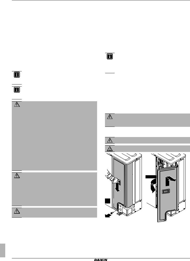
6.2.2To open the outdoor unit
DANGER: RISK OF ELECTROCUTION
DANGER: RISK OF BURNING


 2
2


1× 
45°~90°
3 


(4)


1
6 Installation
6.1Overview: Installation
This chapter describes what you have to do and know on-site to install the system.
Installer reference guide |
RZQG71L9V1L + RZQG71~125L8Y1L + RZQG140L7Y1L |
10 |
Split system air conditioners |
4P473074-1 – 2017.03 |
Loading...