


Daikin RZQ20KCVJK, RZQ24KCVJK, RZQ45LUYAK, RZQ48LUYAK, RZQ36KCVJK Installation manuals [ar]
...00_CV_3P281953-1B.fm Page 1 Frid ay, December 24, 2010 6:37 PM
INSTALLATION MANUAL
ﺐﻴﻛﺮﺘﻟﺍ ﻞﻴﻟﺩ
SPLIT SYSTEM |
Air Conditioner |
ﻢﺴﻘﻨﻤﻟﺍ ﻡﺎﻈﻨﻟﺍ |
ءﺍﻮﻬﻟﺍ ﻒﻴﻴﻜﺗ ﺯﺎﻬﺟ |
|
|
MODELS ﺯﺮﻄﻟﺍ
RZQ20KCVJK RZQ45LUYAK
RZQ24KCVJK RZQ48LUYAK
RZQ36KCVJK
RZQ45KCVJK
English
ﺔﻴﺑﺮﻌﻟﺍ
READ THESE INSTRUCTIONS CAREFULLY BEFORE INSTALLATION. KEEP THIS MANUAL IN A HANDY PLACE FOR FUTURE REFERENCE.
.ﺐﻴﻛﺮﺘﻟﺍ ﻞﺒﻗ ﺔﻳﺎﻨﻌﺑ ﺕﺍﺩﺎﺷﺭﻹﺍ ﻩﺬﻫ ﺃﺮﻗﺍ
.ﺪﻌﺑ ﺎﻤﻴﻓ ﻪﻴﻟﺇ ﻉﻮﺟﺮﻠﻟ ﻪﻴﻟﺇ ﻝﻮﺻﻮﻟﺍ ﻞﻬﺴﻳ ﻥﺎﻜﻣ ﻲﻓ ﻞﻴﻟﺪﻟﺍ ﺍﺬﻬﺑ ﻆﻔﺘﺣﺍ
01_EN_3P281953-1B.fm Page 1 Tuesday, January 25, 2011 3:35 PM
RZQ20KCVJK |
RZQ45LUYAK |
|
||
RZQ24KCVJK |
RZQ48LUYAK |
|
||
RZQ36KCVJK |
SPLIT SYSTEM Air Conditioner |
Installation manual |
||
RZQ45KCVJK |
||||
|
|
|||
|
|
|
|
|
|
CONTENTS |
|
1. |
SAFETY PRECAUTIONS............................................................................................... |
2 |
2. |
BEFORE INSTALLATION .............................................................................................. |
4 |
3. |
SELECTING INSTALLATION SITE................................................................................ |
5 |
4. |
INSTALLATION SERVICING SPACE ............................................................................ |
6 |
5. |
PRECAUTIONS ON INSTALLATION........................................................................... |
10 |
6. |
REFRIGERANT PIPING WORK .................................................................................. |
12 |
7. |
EVACUATING .............................................................................................................. |
19 |
8. |
REFILLING THE REFRIGERANT ................................................................................ |
20 |
9. |
ELECTRICAL WIRING WORK..................................................................................... |
22 |
10. |
ON SITE SETTING AND CHECK ITEMS BEFORE TEST RUN.................................. |
26 |
11. |
ON SITE SETTINGS .................................................................................................... |
27 |
12. |
TEST RUNS ................................................................................................................. |
28 |
IMPORTANT: INSULATION RESISTANCE OF THE COMPRESSOR
If, after installation, refrigerant accumulates in the compressor, the insulation resistance can drop, but if it is at least 1 MΩ, then the machine will not break down.
•Turn on the power and leave it on for six hours. Then, check to see if the insulation resistance of the compressor has risen or not.
The compressor will heat up and evaporate any refrigerant in the compressor.
Check the following items if the earth leakage breaker is triggered.
•Make sure that the interrupter is compatible with harmonics.
This unit has an inverter, so an interrupter capable of handling harmonics is needed to prevent malfunction of the interrupter itself.
1.This unit uses R410A as a refrigerant. For R410A refrigerant, the entry of any impurities (mineral oils such as SUNISO oil and liquids) must be prevented more strictly. Be sure to follow the precautions in chapter
6-1 PRECAUTIONS ON REFRIGERANT PIPING.
2.The design pressure of this unit high pressure area is 4.00 MPa, and the low pressure area is 2.21 MPa. The local inter-unit piping is a high pressure area. Use a local inter-unit piping which supports the design pressure. For the piping specifications, please refer to chapter 6. REFRIGERANT PIPING WORK.
3.R410A is a mixed refrigerant. Be sure to charge additional refrigerant as liquid.
(Charging the additional refrigerant as gas will change the refrigerant composition and prevent normal operation.)
Be sure to connect a R410A indoor unit.
See the catalog for indoor unit models which can be connected. (Normal operation is not possible when connected to other units.)
1 |
|
|
English |
||
|
|
|
|
|
|
|
|
|
|
|
|
|
|
|
|
|
|
01_EN_3P281953-1B.fm Page 2 Tuesday, January 25, 2011 3:35 PM
1. SAFETY PRECAUTIONS
Please read the these "SAFETY CONSIDERATIONS" carefully before installing air conditioning unit and be sure to install it correctly. After completing the installation, make sure that the unit operates properly during the start-up operation.
Please instruct the customer on how to operate the unit and keep it maintained.
Also, inform customers that they should store this installation manual along with the operation manual for future reference.
Meaning of WARNING and CAUTION notices.
Both are important notices for safety. Be sure to follow them.
 WARNING ........Failure to follow these instructions properly may result in personal injury or loss of life.
CAUTION ..........Failure to observe these instructions properly may result in property damage or personal injury, which may be serious depending on the circumstances.
After completing installation, conduct a trial operation to check for faults and explain to the customer how to operate the air conditioner and take care of it with the aid of the operation manual. Ask the customer to store the installation manual along with the operation manual for future reference.
This air conditioner comes under the term “appliances not accessible to the general public”.  WARNING
•Ask your dealer or qualified personnel to carry out installation work.
Do not attempt to install the air conditioner yourself. Improper installation may result in water leakage, electric shocks or fire.
•Install the air conditioner in accordance with the instructions in this installation manual. Improper installation may result in water leakage, electric shocks or fire.
•When installing the unit in a small room, take measures against to keep refrigerant concentration from exceeding allowable safety limits in the event of refrigerant leakage.
Contact the place of purchase for more information. Excessive refrigerant in a closed ambient can lead to oxygen deficiency
•Be sure to use only the specified accessories and parts for installation work.
Failure to use the specified parts may result in the unit falling, water leakage, electric shocks or fire.
•Install the air conditioner on a foundation strong enough to withstand the weight of the unit. A foundation of insufficient strength may result in the equipment falling and causing injury.
•Carry out the specified installation work after taking into account strong winds, typhoons or earthquakes. Failure to do so during installation work may result in the unit falling and causing accidents.
•Make sure that a separate power supply circuit is provided for this unit and that all electrical work is carried out by qualified personnel according to local laws and regulations and this installation manual.
An insufficient power supply capacity or improper electrical construction may lead to electric shocks or fire.
•Be sure to earth the air conditioner.
Do not earth the unit to a utility pipe, lightning conductor or telephone earth lead. Imperfect earthing may result in electric shocks or fire.
A high surge current from lightning or other sources may cause damage to the air conditioner.
•Be sure to install an earth leakage breaker.
Failure to install an earth leakage breaker may result in electric shocks or fire.
•Be sure to switch off the unit before touching any electrical parts. Touching a live part may result in electric shock.
•Make sure that all wiring is secured, the specified wires are used, and that there is no strain on the terminal connections or wires.
Improper connections or securing of wires may result in abnormal heat build-up or fire.
•When wiring the power supply and connecting the wiring between the indoor and outdoor units, position the wires so that the control box lid can be securely fastened.
Improper positioning of the control box lid may result in electric shocks, fire or overheating terminals.
•If refrigerant gas leaks during installation, ventilate the area immediately. Toxic gas may be produced if the refrigerant comes into contact with fire.
•After completing installation, check for refrigerant gas leakage.
Toxic gas may be produced if the refrigerant gas leaks into the room and comes into contact with a source of fire, such as a fan heater, stove or cooker.
•Do not touch any refrigerant that leaks out of refrigerant piping joints or connections. Touching it may cause frostbite.
|
English |
2 |
|||
|
|
|
|
|
|
|
|
|
|
|
|
|
|
|
|
|
|
01_EN_3P281953-1B.fm Page 3 Tuesday, January 25, 2011 3:35 PM
•Do not stand on the outdoor unit or put things on it. This may result in an accident caused by falling or dropping of items.
•Consult your local dealer regarding what to do in case of refrigerant leakage, when the air coditioner is to be installed in a small room, it is necessary to take proper measures so that the amount of any leaked refrigerant does not exceed the concentration limit in the event of leakage. Otherwise, this may lead to an accident due to oxygen depletion.

 CAUTION
•While following the instructions in this installation manual, install drain piping to ensure proper drainage and insulate piping to prevent condensation.
Improper drain piping may result in indoor water leakage and property damage.
•Install the indoor and outdoor units, power cord and connecting wires at least 1 meter away from televisions or radios to prevent picture interference and noise.
(Depending on the incoming signal strength, a distance of 1 meter may not be sufficient to eliminate noise.)
•Install the indoor unit as far away from fluorescent lamps as possible.
Remote controller (wireless kit) transmitting distance can be shorter than expected in rooms with electronic fluorescent lamps (inverter or rapid start types).
•In a domestic environment this product may cause radio interference in which case the user may be required to take adequate measures.
•Do not allow children to climb on the outdoor unit and avoid placing objects on the unit. Injury may result if the unit becomes loose and falls.
•Make sure to provide for adequate measure in order to prevent that the outdoor unit be used as a shelter by small animals.
Small animals making contact with electrical parts can cause malfunctions, smoke or fire. Please instruct the customer to keep the area around the unit clean.
•Install in a machine room that is free of moisture. The unit is designed for indoor use.
•Disposal requirements
Dismantling of the unit, treatment of the refrigerant, of oil and of other parts must be done in accordance with relevant local and national legislation.
•Do not install the air conditioner in the following locations:
1.Where there is a high concentration of mineral oil spray or vapour (e.g. a kitchen). Plastic parts will deteriorate, parts may fall off and water leakage could result.
2.Where corrosive gas, such as sulphurous acid gas, is produced. Also areas that are rich in sodium such as seashores. Corroding of copper pipes or soldered parts may result in refrigerant leakage.
3.Near machinery emitting electromagnetic radiation.
Electromagnetic radiation may disturb the operation of the control system and result in a malfunction of the unit.
4.Where flammable gas may leak, where there is carbon fibre or ignitable dust suspensions in the air, or where volatile flammables such as paint thinner or gasoline are handled.
Operating the unit in such conditions may result in fire.
5.Where small animals may be housed, fallen leaves are accumulated, or weeds are overgrown. If small animals touch the electrical parts inside, this may cause malfunction, smoke or fire.
SPECIAL NOTICE OF PRODUCT
•Refrigerant
•The refrigerant R410A requires that strict Precautions be observed for keeping the system clean, dry and tightly sealed.
A. Clean and Dry
Strict measure must be taken to keep impurities (including SUNISO oil and other mineral oils as well as moisture) out of the system.
B. Tightly sealed
R410A contains no chlorine, does not destroy the ozone layer and so does not reduce the earth’s protcetion against harmful ultraviolet radiation. R410A will contribute only slightly to the greenhouse effect if released into the almosphere
•Since design pressure is 4.0 MPa or 40 bar (for R407C units: 3.3MPa or 33bar), the thickness of pipes must be greater than previously. Since R410A is a mixed refrigerant, the required additional refrigerant must be charged in its liquid state. (If the system is charged with refrigerant in its gaseous state, due to composition change, the system will not function normally). The indoor units is designed for R410A use. See the catalogue for indoor unit models that can be connected. (Normal operation is not possible when connecting units that are originally designed for other refrigerants)
3 |
|
|
English |
||
|
|
|
|
|
|
|
|
|
|
|
|
|
|
|
|
|
|

01_EN_3P281953-1B.fm Page 4 Tuesday, January 25, 2011 3:35 PM
2. BEFORE INSTALLATION
<Do not throw away accessories that are required for installation.>
2-1 READ THESE INSTRUCTIONS CAREFULLY BEFORE INSTALLATION
•See the indoor unit’s installation manual for indoor unit installation.
•The illustration shows a 48 type. Other models also comply with this.
2-2 ACCESSORIES
Make sure that the accessories shown in Fig. 1 are all present. (The accessories can be found behind the front panel.)
Name |
Installation |
Clamp |
Drain socket |
Drain cap |
Drain receiver |
Seal |
|
manual |
|||||||
|
|
|
|
|
|
||
Quantity |
1 |
2 pcs. |
1 |
2 |
3 |
1 |
|
Shape |
|
|
|
|
|
|
Fig. 1
Front panel
Accessories
Screw for front panel
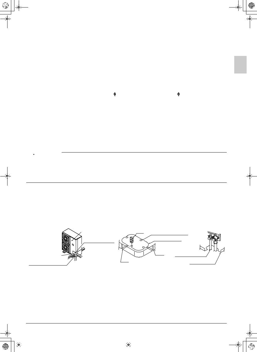
Transporting the Unit
As shown in Fig. 3, bring the unit slowly. (Take care not to let hands or things come in contact with rear fins.)
Intake hole
Air outlet grille
Corner |
|
Outdoor unit |
Handle |
|
|
|
Fig. 2 |
Fig. 3
Do not holding the suction inlet in the side of the casing, otherwise the casing could be deformed. (Place your hands on the corner in the case of 71 class model.)
Take care not to let hands or objects
come in contact with rear fins.
Work in a team of at least two people when carrying the unit.
Only hold the unit at the specified positions when carrying it using PP bands or other items.
Installation Parts
Always use accessory parts or those of designated specification as parts required for installation.
|
English |
4 |
|||
|
|
|
|
|
|
|
|
|
|
|
|
|
|
|
|
|
|
01_EN_3P281953-1B.fm Page 5 Tuesday, January 25, 2011 3:35 PM
3. SELECTING INSTALLATION SITE
(1)Select an installation site where the following conditions are satisfied and that meets with your customer’s approval.
•Places where there is no possibility of flammable gas leak.
•Places where the unit does not bother next-door neighbors.
•Safe places which can withstand the unit’s weight and vibration and where the unit can be installed level.
•Places which are well-ventilated.
•Places where servicing space can be well ensured.
The minimum required space is shown in chapter 4. INSTALLATION SERVICING SPACE.
•Places where the indoor and outdoor unit’s piping and wiring lengths come within the allowable ranges. (Please refer to chapter 6. REFRIGERANT PIPING WORK.)
CAUTION
•Inverter air conditioners may cause noise to occur in electrical appliances.
As shown in the right drawing, select an installation site well away from radios, PCs, and stereos.
•Especially in the areas where the incoming signal strength is weak, keep the indoor remote controller 3 m or more from electrical appliances. Put the power cord and connecting wires in a metal pipe and ground the metal pipe.
|
Branch switch, |
|
over current |
Indoor unit |
breaker |
1 m or more |
|
|
Indoor |
|||||
|
||||||||
|
|
remote |
||||||
|
|
|||||||
|
|
|
|
|||||
1 m or more |
|
|
|
controller |
||||
|
|
|
||||||
|
|
|
|
|
|
|
|
1.5 m or more |
|
|
|
|
|
|
|
|
|
|
|
|
|
|
|
|
|
|
|
|
|
|
|
|
|
|
|
|
|
|
|
|
|
|
|
1.5 m or more |
|
|
|
|
|
|
|
|
|
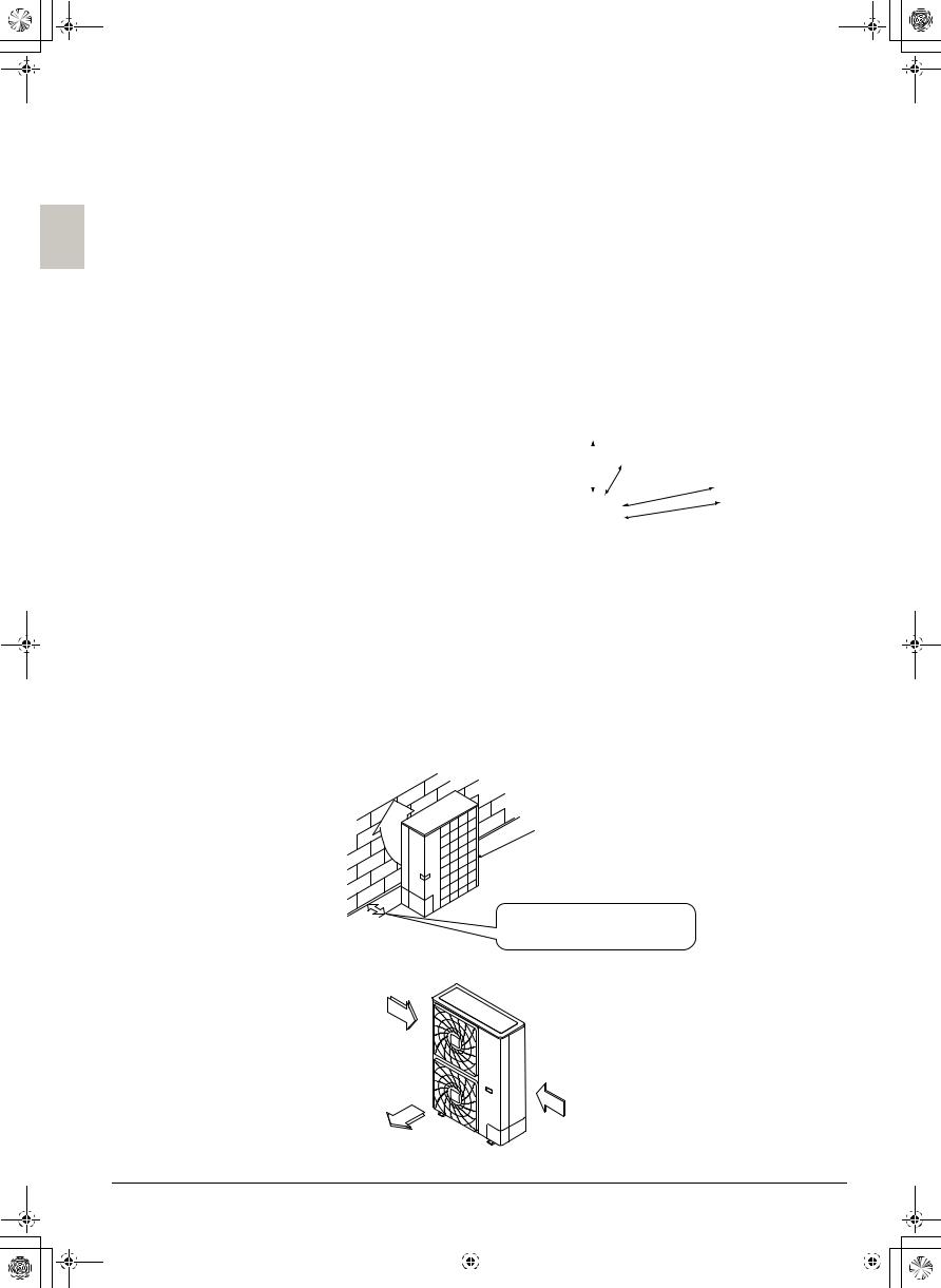
(2)When installing the unit in a place exposed to strong wind, pay special attention to the following.
5 m/sec or more strong wind blown against the outdoor unit’s air outlet causes the outdoor unit to deteriorate in air capacity and suck in the air blown out of its air outlet (short circuit), and the following effects may result.
•Drop in performance.
•Increased frost formation in heating mode.
•Shutting down due to increase in pressure.
If a very high fan strength is used continuously from the front of the outdoor unit outlet side, the fan might turn in reverse at high speed, and become damaged.
• Turn the air outlet side toward the building’s wall, fence or windbreak screen.
Air inlet grille
|
Ensuring there is enough |
Fig. 4 |
space for installing the unit. |
|
• Set the outlet side at a right angle to the direction of the wind.
Strong wind
Strong wind
Blown air
Fig. 5
5 |
|
|
English |
||
|
|
|
|
|
|
|
|
|
|
|
|
|
|
|
|
|
|
01_EN_3P281953-1B.fm Page 6 Tuesday, January 25, 2011 3:35 PM
(3)The refrigerant (R410A) itself is a safe refrigerant that is non-poisonous and non-flammable. How ever, if the refrigerant leaks into a small room, and the refrigerant concentration in the room exceeds the allowable safety limit, measures to deal with the refrigerant leakage are required. For details, please refer to the technical materials.
(4)In installing the unit in a place frequently exposed to snow, pay special attention to the following:
In regions where buildups of snow can be expected, the air inlet and outlet as well as lower section of the bottom plate may be blocked by the snow. Pay special attention to the following:
•Place the outdoor unit on a stand (field supply) so that it is not covered by snow falls, snow buildups, or snow drifts. Ensure the bottom plate is at least 500 mm higher than expected snow levels.
•Install a roof cover for a snow fence or other enclosure (field supply).
•Remove the rear suction grille to prevent snow from accumulating on the rear fins.
•Avoid installing the unit in a location where blown snow will build up.
•Also take the following measures, as there is a danger the drainage discharged during defrosting operation may freeze.
•Install the outdoor unit at a sufficient height so that its bottom plate is above expected snow levels. This is to prevent the buildup of ice on the underside of the bottom plate. (A space of at least 500 mm is recommended.)
•Do not use a centralized drain plug (option). (There is a danger of freezing when a drain plug or drain pipe is used.)
•If there is a problem with dripping of drainage, take a measure such as positioning a roof cover (field supply) under the outdoor unit.
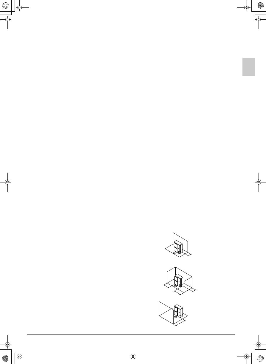
4. INSTALLATION SERVICING SPACE
•The installation service spaces shown in these drawings are based on an outdoor unit intake area temperature of 35°C (DB) for COOL operation. If the planned intake area temperature exceeds 35°C (DB), or if the heat load of all outdoor units is increased significantly and exceeds the maximum operating capacity, secure a larger space than that indicated by the intake dimensions in these drawings.
•For installation, consider both pedestrian and air flow paths and choose a suitable pattern from these drawings to match the space available onsite. (If the number of units to be installed exceeds the patterns in these drawings, consider using short-circuits.)
•Regarding the front space, position the units with consideration to the space required for the onsite refrigerant piping work. (Consult your dealer if the work conditions do not match those in the drawings.)
•The values represent the case for the RZQ20·24 type through RZQ48 type. The dimensions in ( ) are for the RZQ36, RZQ45 and RZQ48 type.
4-1 INSTALLATION OF SINGLE UNIT (Units : mm)
When nothing is obstructing the top
1. In case obstacles exist only in front of the air inlet.
 50 or more (100)
2.In case obstacles exist in front of the air inlet and on both sides of the unit.
100 or more
100 or more |
100 or more |
|
3. In case obstacles exist only in front of outlet side.
500 or more
|
English |
6 |
|||
|
|
|
|
|
|
|
|
|
|
|
|
|
|
|
|
|
|
01_EN_3P281953-1B.fm Page 7 Tuesday, January 25, 2011 3:35 PM
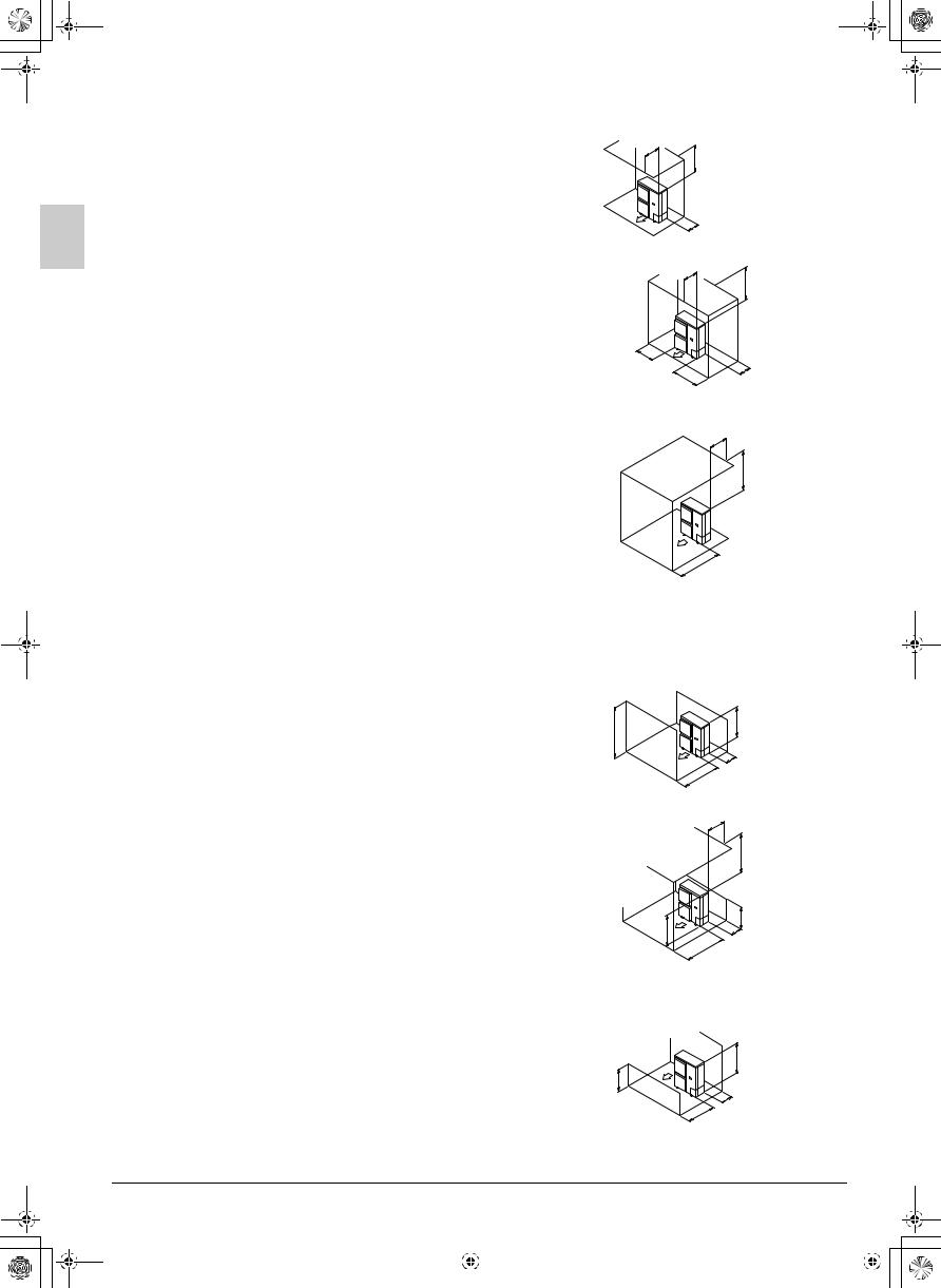
When something is obstructing the top
1. In case obstacles exist in front of the air inlet.
500 or less
1000 or more
100 or more
2.In case obstacles exist in front of the air inlet and on both sides of the unit.
3.In case obstacles exist in front of outlet side.
500 or less
1000 or more
150 or more
150 or more |
150 or more |
|
500 or less
1000 or more
500 or more
In case obstacles exist in front of both the air inlet and outlet sides |
|
|
|
||||||||
Pattern 1 Where obstacle in front of the air outlet is higher than the unit. |
|
|
|
||||||||
1. When nothing is obstructing the top. |
|
|
|
|
|
|
|
|
|||
|
(There is no height limit for obstructions on the intake side.) |
|
|
|
|
|
|
||||
|
L>H |
|
|
|
|
||||||
|
|
|
|
|
|
|
|
L |
|
|
H |
|
|
|
|
|
|
|
|
|
|
|
|
|
|
|
|
|
|
|
|
|
|
|
50 or more |
|
|
|
|
|
|
|
|
|
|
|
(100) |
|
|
|
|
|
|
|
|
|
|
500 or more |
|
2. When something is obstructing the top. |
|
|
|
|
|
|
500 or less |
||||
|
Relation of dimensions of H, A, and L are shown in the table below. |
|
|||||||||
|
|
|
|
||||||||
|
|
|
|
|
|
|
|
|
|
|
|
|
|
|
L |
A |
|
|
|
|
|
|
1000 or more |
|
|
|
|
|
|
|
|
|
|
|
|
|
L ≤ H |
0 < L ≤ 1/2H |
750 or more |
|
|
|
|
|
|
|
|
|
|
|
|
|
|
|
|
|
|
|
|
|
1/2H |
< L ≤ H |
1000 or more |
|
|
|
|
|
|
|
|
|
|
|
|
|
|
|
|
|
|||
|
|
|
|
|
|
|
|
|
|
|
|
|
L > H |
|
Set the frame to be L ≤ H |
|
|
|
|
|
|
L |
|
|
Refer to the column of L ≤ H for A |
|
|
|
|
H |
|
||||
|
|
|
|
|
|
|
150 or more |
||||
|
|
|
|
|
|
|
|
|
|
|
|
|
|
|
|
|
|
|
|
|
|
|
(250) |
|
Get the lower part of the frame sealed so that air from the outlet does |
|
A |
||||||||
|
|
|
|||||||||
|
not bypass. |
|
|
|
|
|
|
|
|
|
|
Pattern 2 Where obstacles in front of the air outlet is lower than the unit. |
|
|
|
||||||||
1. When nothing is obstructing the top. |
|
|
|
|
|
|
|
|
|||
|
(There is no height limit for obstructions on the intake side.) |
|
|
L≤H |
|
|
|
||||
H
L
50 or more
(100)
500 or more
7 |
|
|
English |
||
|
|
|
|
|
|
|
|
|
|
|
|
|
|
|
|
|
|
01_EN_3P281953-1B.fm Page 8 Tuesday, January 25, 2011 3:35 PM
2. When something is obstructing the top.
Relation of dimensions of H, A, and L are shown in the table below.
|
|
L |
A |
|
|
|
|
||
L ≤ H |
0 < L ≤ 1/2H |
50 (100) or more |
||
|
|
|
||
1/2H |
< L ≤ H |
100 (200) or more |
||
|
||||
|
|
|
|
|
L > H |
|
Set the frame to be L ≤ H |
||
Refer to the column of L ≤ H for A |
||||
|
||||
|
|
|
|
|
Get the lower part of the frame sealed so that air from the outlet does not bypass.
500 or less
1000 or more
H
L
A
500 or more
(1000)
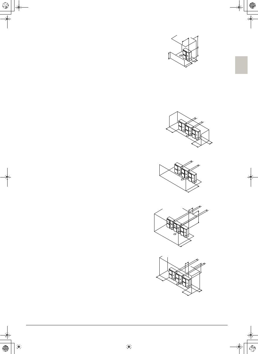
4-2 IN CASE OF INSTALLING MULTIPLE UNITS (2 UNITS OR MORE) IN LATERAL CONNECTION PER ROW (Units : mm)
• Secure appropriate space when using a side piping outlet.
When nothing is obstructing the top
1.In case obstacles exist in front of the air inlet and on both sides of the unit.
100 or more
100 or more
1000 or more
200 or more |
200 or more |
|
(300) |
2. When something is obstructing the outlet side.
When something is obstructing the top
1. In case obstacles exist in front of outlet side.
100 or more
100 or more
1000 or more
100 or
500 or less more 100 or more
1000 or more
1000 or more
2.In case obstacles exist in front of the air inlet and on both sides of the unit.
|
100 or |
|
500 |
more |
|
100 or |
||
or less |
||
more |
||
|
||
|
1000 or more |
1000 or more
200 or more |
200 or more |
(300) |
|
English |
8 |
|||
|
|
|
|
|
|
|
|
|
|
|
|
|
|
|
|
|
|
01_EN_3P281953-1B.fm Page 9 Tuesday, January 25, 2011 3:35 PM
In case obstacles exist in front of both the air inlet and outlet sides |
|
||||
Pattern 1 Where obstacle in front of the air outlet is higher than the unit. |
|
||||
1. When nothing is obstructing the top. |
|
100 or |
|||
(There is no height limit for obstructions on the intake side.) |
more |
||||
|
|
|
L>H |
100 or |
|
|
|
|
more |
||
|
|
|
|
||
|
|
|
L |
H |
|
|
|
|
|
||
|
|
|
|
200 or more |
|
|
|
|
|
(300) |
|
|
|
|
|
1000 or more |
|
2. When something is obstructing the top. |
|
500 or less |
|||
Relation of dimensions of H, A, and L are shown in the table below. |
|||||
100 or |
|||||
|
|
|
|
||
|
|
L |
A |
more |
|
L ≤ H |
0 < L ≤ 1/2H |
1000 or more |
1000 or more |
||
1/2H |
< L ≤ H |
1250 or more |
|
||
|
|
||||
L > H |
|
Set the frame to be L ≤ H |
|
||
Refer to the column of L ≤ H for A |
L |
||||
|
|||||
|
|
|
|
H |
|
Get the lower part of the frame sealed so that air from the outlet does |
200 or more |
||||
not bypass. |
|
|
|
(300) |
|
|
|
|
A |
||
Only two units at most can be installed in series.
Pattern 2 Where obstacles in front of the air outlet is lower than the unit. |
|
|
|
|
1. When nothing is obstructing the top. |
|
|
|
100 or |
(There is no height limit for obstructions on the intake side.) |
|
|
more 100 or |
|
Relation of dimensions of H, A, and L are shown in the table below. |
|
|
more |
|
|
|
|
||
L |
A |
L |
|
H |
0 < L ≤ 1/2H |
150 (250) or more |
|
|
|
1/2H < L ≤ H |
200 (300) or more |
|
|
A |
|
|
|
|
1000 or more |
2. When something is obstructing the top. |
|
|
|
(1500) |
|
|
500 |
100 or |
|
Relation of dimensions of H, A, and L are shown in the table below. |
|
|||
|
or less |
|||
|
more |
|||
|
|
|
|
|
|
|
L |
A |
|
|
|
|
|
|
||
L ≤ H |
0 < L ≤ 1/2H |
150 (250) or more |
|
||
|
|
|
|
||
1/2H |
< L ≤ H |
200 (300) or more |
L |
||
|
|||||
|
|
|
|
|
|
L > H |
|
Set the frame to be L ≤ H |
|
||
Refer to the column of L ≤ H for A |
|
||||
|
|
||||
|
|
|
|
|
|
Get the lower part of the frame sealed so that air from the outlet does not bypass.
1000 or more
H
A
1000 or more
(1500)
Only two units at most can be installed in series.
If the dimensions exceed the values in the brackets, the stand does not have to be installed even when H is lower than L.
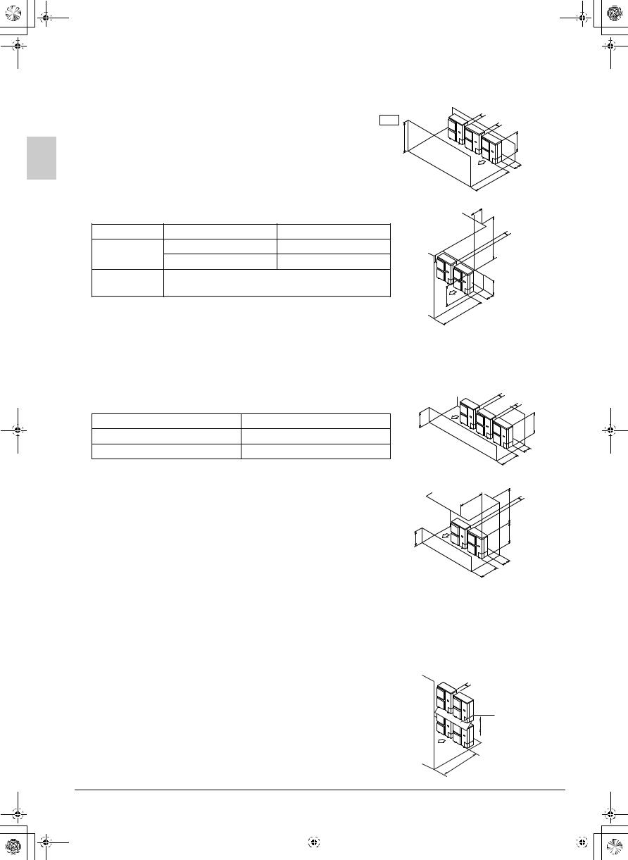
4-3 IN CASE OF STACKED INSTALLATION (Units : mm)
1. In case obstacles exist in front of the outlet side.
100 or more
A
 500 or more
1000 or more
9 |
|
|
English |
||
|
|
|
|
|
|
|
|
|
|
|
|
|
|
|
|
|
|
01_EN_3P281953-1B.fm Page 10 Tu esday, January 25, 2011 3:35 PM
2. In case obstacles exist in front of the air inlet.
100 or  more
more
A
 500 or more
200 or more
(300)
•Do not exceed two levels for stacked installation.
•Install a roof cover similar to A (field supply), as outdoor units with downward drainage are prone to dripping and freezing.
•Install the upper-level outdoor unit so that its bottom plate is a sufficient height above the roof cover. This is to prevent the buildup of ice on the underside of the bottom plate. (A space of at least 500 mm is recommended.)
•It is not necessary to install a roof cover if there is no danger of drainage dripping and freezing. In this case, the space between the upper and lower outdoor units should be at least 100 mm. (Close off the gap between the upper and lower units so there is no reintake of discharged air.)
4-4 IN CASE OF MULTIPLE-ROW INSTALLATION (FOR ROOF TOP USE, ETC.) (Units : mm)
1. In case of installing one unit per row.
2.In case of installing multiple units (2 units or more) in lateral connection per row.
Relation of dimensions of H, A, and L are shown in the table below.
|
|
L |
A |
|
|
|
|
||
L ≤ H |
0 < L ≤ 1/2H |
150 (250) or more |
||
|
|
|
||
1/2H |
< L ≤ H |
200 (300) or more |
||
|
||||
|
|
|
|
|
L > H |
|
Installation impossible. |
||
50 or more
(100)
1000 or more
(2000)
100 or more
(200)
500 or more
(1000)
100 or more |
|
|
100 or more |
100 or |
|
more |
|
100 or |
|
more |
L |
|
A |
100 or |
2000 or more |
more 100 or |
(3000) |
more H |
400 or more |
|
(600) |
1000 or more
(1500)
5. PRECAUTIONS ON INSTALLATION
Drain pipe disposal
•Potentially problematic locations for outdoor unit drainage
In locations where, for example, drainage may fall on passersby or frozen drainage may cause passersby to slip over, install an enclosure (field supply) to prevent people approaching the outdoor unit.
•In regions where buildups of snow can be expected, the accumulation and freezing of snow in the space between the heat exchanger and external plate may lower operating efficiency.
In this case, drill a knock hole in the lower part of the bottom frame so the snow can escape. When creating a knock hole, use a φ6 mm drill bit to open round holes around the circumference of the knock hole (4 places).
|
English |
10 |
|||
|
|
|
|
|
|
|
|
|
|
|
|
|
|
|
|
|
|
01_EN_3P281953-1B.fm Page 11 Tu esday, January 25, 2011 3:35 PM
•After punching the knock hole, the application of repair-type paint on the surface around the edge sections is recommended to prevent rust.
|
Air outlet side |
|
|
|
|
| <![if ! IE]> <![endif]>30 |
|
140 |
620 |
140 |
|
| <![if ! IE]> <![endif]>289 |
<![if ! IE]> <![endif]>219 |
<![if ! IE]> <![endif]>117 |
|
<![if ! IE]> <![endif]>350 |
<![if ! IE]> <![endif]>(345– 355) |
|
|
47 |
|
|
|
|
|
421 |
|
Drain hole |
|
|
|
612 |
|
|
|
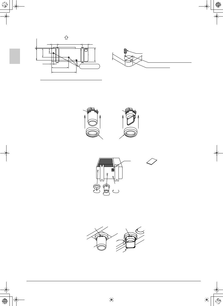
Diagram of lower surface (Units : mm)
Drill
Area around knockout hole Knockout hole
Installation procedure of a central drain plug
1.Insert drain receiver (3) onto drain socket (1) and drain cap (2) beyond 4 projections around drain socket and drain cap.
Drain socket (1) |
Drain cap (2) |
Projections Projections
Drain receiver (3)
2.Insert drain socket and drain caps into their matching drain hole; Drain socket (1) into drain hole B and drain caps (2) into drain hole C and D. After insertion, turn them about 40° clockwise.
|
|
Seal (4) |
D |
A |
(Be sure not to insert them |
|
B |
|
|
C |
into wrong drain holse, or |
|
|
there causes water leakage.) |
 (View from bottom)
NOTE

•Please check whether drain receiver (3) is caught in four projections of drain socket (1) and drain cap (2) correctly.
It will become the cause of the leak they are not attached correctly.
Projection |
Projection |
(4 places) |
(4 places) |
3.Connect vinyl hose on the market (internal diameter of 25mm) to drain socket (1). (If the house is too long and hangs down, fix it carefully to prevent the kinks.)
4.Affix seal (4) to part A as shown on the above drawing.
5.Please check whether there is any leak from A - D each portion.
11 |
|
|
English |
||
|
|
|
|
|
|
|
|
|
|
|
|
|
|
|
|
|
|
01_EN_3P281953-1B.fm Page 12 Tu esday, January 25, 2011 3:35 PM
NOTE

•If the drain holes of the outdoor unit are covered with the mounting bracket or the floor, raise the unit to provide the space of more than 100 mm under the leg of the outdoor unit.
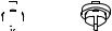
Installation method of outdoor unit
•Check the strength and level of the installation ground so that the unit will not cause any operating vibration or noise after installation.
•In accordance with the foundation drawing in Fig. 6, fix the unit securely by means of the foundation bolts. (Prepare four sets of M12 foundation bolts, nuts and washers each which are available on the market.)
| <![if ! IE]> <![endif]>20 |
Drawing of the foundation
Fig. 6
•It is best to screw in the foundation bolts until their length are 20 mm from the foundation surface.
•Fix the outdoor unit to the foundation bolts using nuts with resin washers. Resin
(Refer to the right-hand drawing.) |
washers |
|
If the coating on the fastening area is stripped off, the nuts rust easily. |
||
|
Installation method of fitting for prevention of overturning
• If steps need to be taken to prevent the unit from tipping over, use the tipping prevention clasps (option).
Tipping prevention clasps (option) (Wiring system)
6. REFRIGERANT PIPING WORK
6-1 PRECAUTIONS ON REFRIGERANT PIPING
See the indoor unit’s installation manual for details on the refrigerant piping for indoor units.

 CAUTION
To plumbing persons
•Use R410A as additional refrigerant for charging.
•Do not use a flux when brazing the refrigerant pipe joints. Use phosphor copper brazing (BCuP) which does not require flux.
(Using a chlorine flux may cause the pipes to corrode, and if it contains fluoride it may cause the refrigerant lubricant to deteriorate, adversely affecting the refrigerant piping system.)
•After chapter 8. REFILLING THE REFRIGERANT is completed, be sure to open the stop valves before performing 11. ON SITE SETTINGS.
(Operating the unit with the valve shut will break the compressor.)
|
English |
12 |
|||
|
|
|
|
|
|
|
|
|
|
|
|
|
|
|
|
|
|
01_EN_3P281953-1B.fm Page 13 Tu esday, January 25, 2011 3:35 PM
Precautions when re-using pre-existing refrigerant piping
•Abide by the following when re-using pre-existing refrigerant piping. Any problems with the piping may lead to malfunctioning.
•In the following cases, do not re-use piping, but rather lay new piping.
·If indoor or outdoor units have been disconnected from the piping for a long time (as water and foreign matter might have entered the piping).
·If copper piping is corroded.
•Flares should be redone and not re-used, in order to prevent refrigerant leaks.
•Do not reuse the flare nuts. Instead, use the flare nuts included with the product.
•Check for refrigerant leaks on welded areas if the pre-existing piping has been welded anywhere.
•Replace any deteriorated insulation with new insulation.
6-2 INSTALLATION TOOLS
Be sure to use the dedicated tools to ensure sufficient pressure resistance and prevent the entry of any impurities.
Manifold gauge |
To ensure sufficient pressure resistance and prevent the entry of any impurities (mineral |
|
oils such as Suniso oil and liquids), use the R410A dedicated item (the screw specifica- |
||
Charging hose |
||
tions for R410A and R407C differ). |
||
|
||
|
|
|
|
Be extremely careful not to flow the pump oil backward to inside the piping when the |
|
Vacuum pump |
pump is stopped. |
|
|
Use a pump whose gauge pressure can vacuum up to –0.1 MPa (–755 mmHg). |
|
|
|
6-3 SELECTING PIPING MATERIALS
Use the piping whose inside and outside are clean and with no harmful substances for use such as sulphur, oxide, dust, dust from cutting, grease, or liquid (contamination) is attached.
For the refrigerant piping, use the following material. Material: Deoxidised phosphorous seamless copper pipe
Thickness and size: Decide based on section 6-5 REFRIGERANT PIPE SIZE AND ALLOWABLE PIPE LENGTH.
For the handling of the stop valves, refer to “Precautions when the handling piping stop valves” in section 6-6 REFRIGERANT PIPING WORK.
Be sure to perform piping work using measurements within the maximum allowable length and height difference described in 6-5 REFRIGERANT PIPE SIZE AND ALLOWABLE PIPE LENGTH.
6-4 PIPING PROTECTION
Protect the piping and prevent liquid, dirt and dust from entering into the piping.
Pay special attention when running the copper pipe through the through-hole or when leading the edge of the pipe outside the room.
Location |
Work period |
Protection method |
|
Outdoor |
One month or more |
Pinching |
|
|
|
||
Less than one month |
Pinching or taping |
||
|
|||
|
|
|
|
|
|
|
|
Location |
Work period |
Protection method |
|
|
|
|
|
Indoor |
N/A |
Pinching or taping |
|
|
|
|
13 |
|
|
English |
||
|
|
|
|
|
|
|
|
|
|
|
|
|
|
|
|
|
|
01_EN_3P281953-1B.fm Page 14 Tu esday, January 25, 2011 3:35 PM
6-5 REFRIGERANT PIPE SIZE AND ALLOWABLE PIPE LENGTH
 Piping bend radius
Piping diameter |
Piping thickness |
Bend radius |
|
|
|
φ9.5mm |
0.8mm |
30mm or more |
φ15.9mm |
1.0mm |
50mm or more |
CAUTION
The maximum allowable pipe length differs depending on the model. Please refer to the table below.
(1) Refrigerant pipe size
|
|
|
|
|
|
(mm) |
|
|
|
|
|
|
|
Outdoor unit capacity |
|
Liquid pipe |
|
|
Gas pipe |
|
|
|
|
|
|
|
|
20 · 24 · 36 · 45 · 48 type |
|
φ9.5 × t0.8 |
|
φ15.9 × t1.0 |
||
|
|
|
|
|
|
|
(2) Allowable pipe length |
|
|
|
|
|
|
|
|
|
|
|
||
Outdoor unit capacity |
|
Maximum allowable pipe length |
|
Maximum allowable |
||
|
(It is equivalent length in the inside) |
|
height difference |
|||
|
|
|
||||
|
|
|
|
|
|
|
20 · 24 type |
|
|
50m (70m) |
|
30m |
|
|
|
|
|
|
|
|
36 · 45 · 48 type |
|
|
70m (90m) |
|
30m |
|
|
|
|
|
|
|
|
•Equivalent length is the pressure loss due to L joints, traps, and so on along the refrigerant piping converted to a straight piping length of the same size and added to the overall value.

 CAUTION
•Do not use pipe cutters and flare tools which have been used with refrigerant other than R410A.
•When connecting the flares, coat the flare section with ether oil or ester oil.
•Only use the flare nuts included with the unit. Using different flare nuts (one type) may cause the refrigerant to leak.
•In order to prevent dirt, liquid or dust from entering the piping, cure the piping with a pinch or taping.
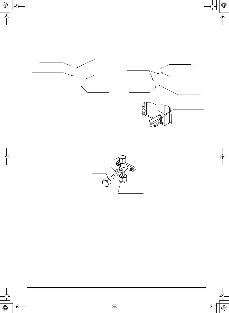
6-6 REFRIGERANT PIPING WORK
•The local interunit piping is connectable in four directions. (Refer to Fig. 7)
•Do not let anything other than the designated refrigerant (such as air or water) enter the refrigerant system.
•When connecting in a downward direction, make four round holes using a 6-mm diameter drill in the central section around the knock hole and open the knock hole. (Refer to Fig. 8)
•Cutting out the two slits makes it possible to install as shown in Fig. 9. (Use a metal saw to cut out the slits.)
|
Front panel |
Dril |
Center area around |
|
|
knock hole |
|
||
|
|
|
||
|
|
|
|
|
|
Pipe outlet panel |
|
Knock hole |
|
|
|
|
|
|
|
Backward |
|
|
|
Screw for front panel |
|
|
Slit |
Connecting pipe |
Forward |
|
|
|
|
Sideways |
Slit |
|
Bottom frame |
|
Pipe outlet panel screw |
Downward |
|
|
|
Fig. 7 |
Fig. 8 |
|
Fig. 9 |
|
|
English |
14 |
|||
|
|
|
|
|
|
|
|
|
|
|
|
|
|
|
|
|
|
01_EN_3P281953-1B.fm Page 15 Tu esday, January 25, 2011 3:35 PM
*After knocking out the knock hole, it is recommended to apply repair paint to the edge and the surrounding end surfaces to prevent rusting.
|
Back side (rear) connection |
|
Side (lateral) connection |
|
|
Remove the piping outlet plate |
|
Remove the piping outlet |
|
|
(rear) for connection. |
Piping on the |
plate (front) for connection. |
|
|
|
|
|
|
|
Flare nut |
liquid side |
|
|
|
(field supply) |
Piping on |
Flare nut |
|
|
|
|||
|
Piping on gas side |
Piping outlet |
gas side |
Piping on the |
|
plate (rear) |
(field supply) |
||
|
(field supply) |
liquid side |
||
|
|
|
||
(field supply)
Knock hole |
Knock hole |
Piping outlet |
|
plate (front) |
|||
|
|
Preventing foreign objects from entering |
Putty or insulating |
|
Plug the pipe through-holes with putty or insulating material |
||
material |
||
(procured locally) to stop up all gaps, as shown in Fig. 10. |
||
(Procured locally) |
||
Insects or small animals entering the outdoor unit may cause a short |
||
|
||
in the control box. |
|
|
|
Fig. 10 |
Precautions when the handling piping stop valve
Do not open the stop valves until the 7. EVACUATING is finished.
•The names of the parts necessary for handling the pipe stop valves for the indoor and outdoor units are described in Fig. 11. The valves are closed before shipment.
Servicing port
Valve bar
Valve lid
|
Branch piping |
Fig. 11 |
connection |
•Since the side boards may be deformed if only a torque wrench is used when loosening or tightening flare nuts, always lock the shut-off valve with a wrench and then use a torque wrench.
When tightening the flare of the stop valve, do not exceed the rated torque. The rated torque is shown on page 16.
Applying force by exceeding the rated tightening torque may cause the sheet surface inside the stop valve to twist, the refrigerant to leak inside the valve, and the flare nut to break.
15 |
|
|
English |
||
|
|
|
|
|
|
|
|
|
|
|
|
|
|
|
|
|
|
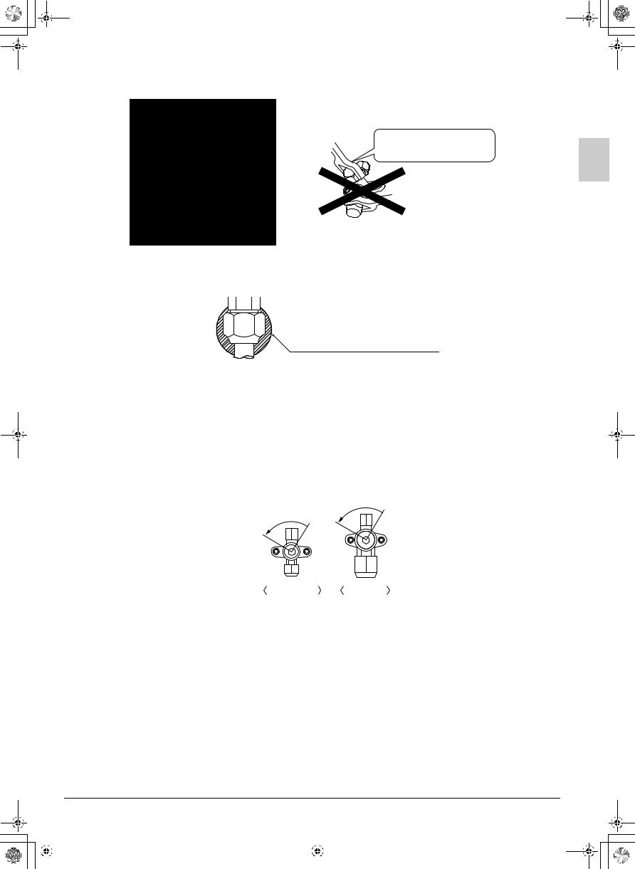
01_EN_3P281953-1B.fm Page 16 Tu esday, January 25, 2011 3:35 PM
Do not apply force to the valve lid.
Using a wrench on the valve lid or body may cause refrigerant to leak.
Do not use wrenches
on the valve lid or body.
 Spanner
Torque  wrench
•When using the low outdoor temperature heating mode, the pressure on the low pressure side might drop, so the flare nut on the stop valve should be sealed completely with silicon sealant or the like in order to prevent frost from forming on it (both gas and liquid sides). (Refer to Fig. 12)
|
Silicon sealing pad |
Fig. 12 |
(Make sure that there is no gap) |
How to Operate the Stop Valve (Refer to Fig. 13)
Use hexagonal wrenches 4 mm and 6 mm.
To open:
1.Insert one hex wrench onto the valve rod and turn counter-clockwise.
2.Stop when the valve rod no longer turns. It is now open.
To close:
1.Insert one hex wrench onto the valve rod and turn clockwise.
2.Stop when the valve rod no longer turns. It is now closed.
Direction to open
Direction to open
Fig. 13 Liquid side |
Gas side |
Precautions for handling valve lid
•A seal is attached to the point indicated by the arrow. Take care not to damage it. (Refer to Fig. 14)
•Be sure to tighten the valve lid securely after operating the valves. Tightening torque
Liquid side |
Gas side |
|
|
13.5 – 16.5N · m |
22.5 – 27.5N · m |
|
|
|
English |
16 |
|||
|
|
|
|
|
|
|
|
|
|
|
|
|
|
|
|
|
|

01_EN_3P281953-1B.fm Page 17 Tu esday, January 25, 2011 3:35 PM
Valve lid
|
Stop valve (lid attachment) |
Fig. 14 |
|
|
|
|
|
Precautions for handling servicing port
•Use a push-rod-provided charging hose for operation.
•Be sure to tighten the valve lid securely after operation. Tightening torque
11.5– 13.9N · m
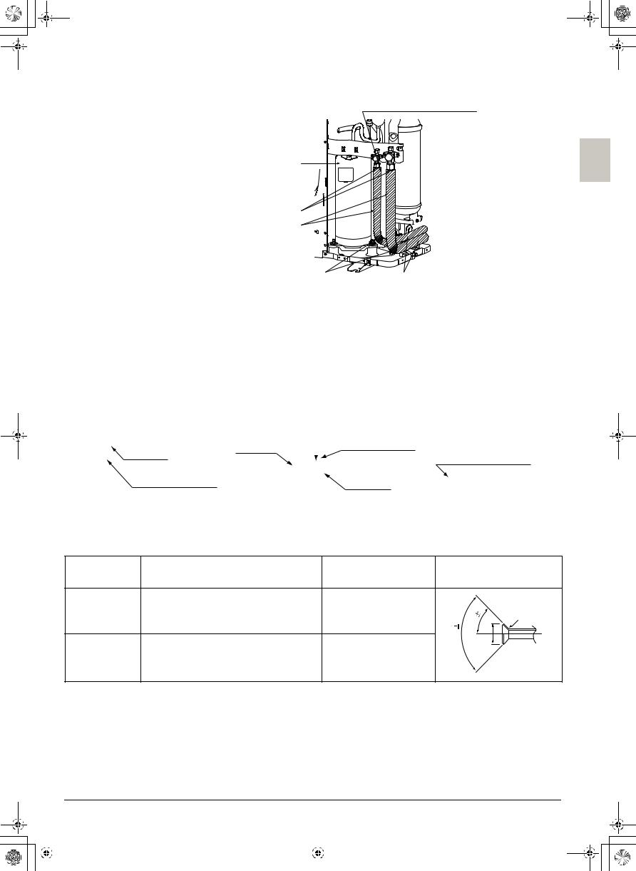
Precautions for connecting pipes
•Avoid the connection pipes of indoor and outdoor units from getting in contact with the terminal of the compressor.
•If installing the outdoor unit higher than the indoor unit, caulk the space around insulation and tubes because condensation on the check valve can seep through to the indoor unit side. Adjust the height of the insulation material on liquid pipe when it has the possibility of getting in contact with the terminal. Also make sure that the connecting piping does not touch the mounting bolt of the compressor.
(Refer to Fig. 15)
Precautions regarding insulation
Enhance the insulating material of the refrigerant piping according to the installation conditions. If this is not done, condensation may form on the surface of the insulation material. Please refer to the target values shown below.
•When the temperature and humidity conditions are 30°C and RH 75% or more: thickness of the insulation material is 15 mm or more.
•When the temperature and humidity conditions are 30°C and RH 80% or more: thickness of the insulation material is 20 mm or more.
•Always insulate the liquid and gas-side interunit piping as well as the refrigerant branch kit. (Not insulating them may cause leaking.)
(The highest temperature that the gas-side piping can reach is around 120°C, so be sure to use insulating material which is very resistant.)
CAUTION
For local insulation, be sure to insulate all the way to the pipe connections inside the unit. (Exposed piping may cause leaking or burns on contact.)
17 |
|
|
English |
||
|
|
|
|
|
|
|
|
|
|
|
|
|
|
|
|
|
|
01_EN_3P281953-1B.fm Page 18 Tu esday, January 25, 2011 3:35 PM
Inter unit piping for the Indoor and outdoor units
Compressor
Perform treatment such as caulking
Insulation (field supply)
Wind heat insulation material around the piping section so it is not exposed and then cover the insulation material with vinyl tape.
Precautions when tightening flare nuts
Insulation (field supply)
Fig. 15
•Be sure to remove the flare nuts using two spanners. Then after the piping connection, tighten them using a spanner and torque wrench.
•Please refer to the Table 1 for the dimensions for processing flares.
•When connecting the flare nut, coat the flare inner surface with refrigerating machine oil and initially tighten by hand 3 or 4 turns before tightening firmly.
|
Torque |
Spanner |
|
|
|
|
|
|
Union tube joint |
||
Flare nut |
wrench |
||
|
|
|
|
|
|
|
|
Connecting piping |
|
|
|
connecting section |
|
Flare nut |
|
|
|
||
Coat the flare inner surface only with ether oil or ester oil.
•Please refer to the Table 1 for the tightening torque. (Too much tightening will end up in splitting of the flare.)
•After all the piping has been connected, use nitrogen to perform a refrigerant leak check.
Table 1
Pipe size |
Tightening torque |
A dimensions for |
|
Flare shape |
||
processing flares (mm) |
|
|||||
|
|
|
|
|
|
|
φ 9.5 |
32.7 – 39.9 N·m |
12.8 – 13.2 |
<![if ! IE]> <![endif]>2˚ |
45˚ |
2˚ |
R0.4-0.8 |
|
|
|
|
|||
|
|
|
|
|
||
|
|
|
<![if ! IE]> <![endif]>90˚ |
|
A |
|
|
|
|
|
|
|
|
φ 15.9 |
61.8 – 75.4 N·m |
19.3 – 19.7 |
|
|
|
|
|
English |
18 |
|||
|
|
|
|
|
|
|
|
|
|
|
|
|
|
|
|
|
|
01_EN_3P281953-1B.fm Page 19 Tu esday, January 25, 2011 3:35 PM
You must use a torque wrench but if you are obliged to install the unit without a torque wrench, you may follow the installation method mentioned below.
When you keep on tightening the flare nut with a spanner, there is a point where the tightening torque suddenly increases. From that position, further tighten the flare nut the angle shown below:
|
|
|
Pipe size |
Further tightening angle |
Recommended arm length of tool |
|
|||||
|
|
|
|
|
|
|
|
|
φ 9.5 |
60 to 90 degrees |
Approx. 200mm |
|
|
|
|
|
|
|
|
|
φ 15.9 |
30 to 60 degrees |
Approx. 300mm |
|
|
|
|
|
|
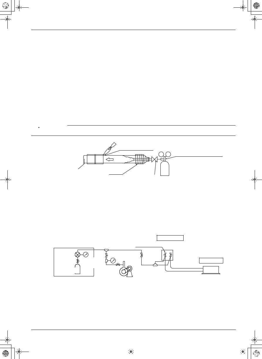
Precautions when brazing piping
Be sure to perform a nitrogen blow when brazing.
(Brazing without carrying out nitrogen replacement or releasing nitrogen into the piping will create large quantities of oxidized film on the inside of the pipes, adversely affecting valves and compressors in the refrigerating system and preventing normal operation.)
•See the Installation manual (available at Daikin dealers) for details on how to perform nitrogen replacement.
•When feeding nitrogen into the pipes while doing the brazing, the letdown valve should be set to 0.02MPa (i.e. it should feel like a slight breeze if blown on your cheek).

 CAUTION
Do not use anti-oxidants when brazing the pipe joints. (Residue can clog pipes and break equipment.)
Part to be brazed
Pressure-reducing valve
Nitrogen |
|
|
Refrigerant piping |
|
|
Taping |
Hands valve |
Nitrogen |
|
|
7. EVACUATING
•Perform a refrigerant leak check using nitrogen gas (airtightness test) with the outdoor unit stop valves close, to make sure there are no leaks.
For the airtightness test, raise the pressure to the design pressure in the high pressure section. (4.0 MPa)
•Do not forget to perform an air purge of the refrigerant system using a vacuum pump.
|
Outdoor unit |
|
Stop valve |
Pressure |
Indoor unit |
gauge |
|
Nitrogen |
|
(Refrigerant leak check) |
Vacuum pump |
NOTE

•After doing an air-purge with a vacuum pump, the refrigerant pressure may not rise even if the stop valve is opened. This is because the refrigerant piping path is closed off by the outdoor unit electronic expansion valve, etc.
There are no problems if the unit is run.
19 |
|
|
English |
||
|
|
|
|
|
|
|
|
|
|
|
|
|
|
|
|
|
|
 Loading...