


Installation, use and maintenance manual
Rooftop Packaged Unit
R-32 rooftop series – Base, 2-,3- and 4-damper versions
Made-To-Stock models
UATYA-BBAY1
UATYA-BBC2Y1
UATYA-BBC3Y1
Made-To-Order models
BASE
FC2
FC3
FC4
Installation, use and maintenance manual Rooftop Packaged Unit
Montageund Betriebsanleitung
Roof-Top-Monoblock-Einheit
Manuel d'installation, d'utilisation et d'entretien Roof top unité de type monobloc
Handleiding voor installatie, gebruik en onderhoud Eenheid monoblok-rooftop
Manual de instalación, uso y mantenimiento Unidad monobloque Roof Top
Manuale installazione uso e manutenzione Rooftop unità monoblocco
Εγχειρίδιο εγκατάστασης, χρήσης και συντήρησης Μονάδα οροφής μονομπλόκ
Manual de instalação, uso e manutenção Rooftop unidade monobloco
Návod k instalaci a údržbě
Rooftop monolitní jednotka
Telepítési, kezelési és karbantartási útmutató
Tetőtéri egység
English
Deutsch
Français
Nederlands
Español
Italiano
ελληνικά
Português
Čeština
Magyar


|
|
Contents |
|
|
|
1 |
Introduction |
|
7 |
|
|
|
1.1 |
Conformity |
|
7 |
|
|
1.2 |
Description |
|
7 |
|
|
1.2.1 |
Symbols |
|
7 |
|
|
1.2.2 |
Labels |
|
8 |
|
2 |
Safety |
|
9 |
|
|
|
2.1 |
General safety precautions |
|
9 |
|
|
2.1.1 Discharge of the safety valves |
|
10 |
|
|
|
2.1.2 |
Emergency stop |
|
10 |
|
|
2.2 |
Basic rules |
|
11 |
|
|
2.2.1 Limits to the use – Minimum area of the conditioned space and maximum refrigerant charge |
13 |
|
||
|
2.2.2 |
Refrigerant leak detector |
|
15 |
|
|
2.2.3 Water flow rate at the heat exchangers |
|
16 |
|
|
|
2.2.4 |
Water composition |
|
16 |
|
|
2.2.5 Warnings concerning flammable refrigerants |
|
17 |
|
|
|
2.3 |
Noise |
|
23 |
|
|
2.4 |
Residual risks |
|
23 |
|
|
2.5 |
Safety information on the refrigerant fluid |
|
24 |
|
|
2.5.1 Hazards and health consequences |
|
24 |
|
|
3 Receiving the product and storage |
|
25 |
|
||
|
3.1 |
Reception |
|
25 |
|
|
3.2 |
Transport |
|
25 |
|
|
3.3 |
Handling |
|
26 |
|
4 |
Product description |
|
28 |
|
|
|
|
||||
|
4.1 |
Intended use |
|
28 |
|
|
4.2 |
Unintended use |
|
28 |
|
|
4.3 |
Control and safety devices |
|
29 |
|
|
4.4 |
Principles of operation |
|
29 |
|
|
4.5 |
Structure |
|
29 |
|
|
4.6 |
Specifications |
|
29 |
|
|
4.7 |
Air system |
|
30 |
|
|
4.7.1 |
Internal air fans |
|
30 |
|
|
4.7.2 Flow rate sensor for fans |
|
30 |
|
|
|
4.7.3 |
Dirty filter sensor |
|
31 |
|
|
4.7.4 |
Air filters |
|
31 |
|
|
4.7.5 Humidifier |
|
31 |
|
|
|
4.8 |
Control panel |
|
32 |
|
|
4.8.1 Switch the unit on and off from the display. |
|
32 |
|
|
|
4.8.2 Switch the unit on and off from external OK signal |
|
32 |
|
|
|
4.8.3 Change of set points |
|
33 |
|
|
We reserve the right to make changes without any prior notice. |
Translation from original instructions |
|
|||
UATYA |
Packaged Rooftop |
4P645202-1 |
3 |
|

|
|
4.8.4 Time band setup procedure |
33 |
|
|
|
4.8.5 |
Change language |
33 |
|
|
4.8.6 Change date and time |
33 |
|
|
|
4.9 |
Wiring diagram |
33 |
5 |
Installation |
34 |
||
|
|
5.1 |
Dimensions and weight |
34 |
|
|
5.2 |
Installation site |
34 |
|
|
5.3 |
Installation |
35 |
|
|
5.3.1 |
External positioning |
35 |
|
|
5.3.2 Fitting of rain hoods |
36 |
|
|
|
5.3.3 |
Anti-vibration mounts |
36 |
|
|
5.3.4 |
Noise attenuation |
37 |
|
|
5.3.5 |
Minimum distances |
37 |
|
|
5.4 |
Hydraulic connections |
38 |
|
|
5.4.1 Hot water coil connection |
38 |
|
|
|
5.4.2 Condensate drain of the internal air coil |
38 |
|
|
|
5.4.3 Condensate drain of the external air coil |
39 |
|
|
|
5.4.4 Connection to the humidifier |
39 |
|
|
|
5.5 |
Electrical connections |
40 |
|
|
5.6 |
Aeraulic connections |
42 |
|
|
5.6.1 Return and supply ducts |
42 |
|
|
|
5.6.2 Connection of the ducts |
43 |
|
6 |
Commissioning |
44 |
||
|
|
6.1 |
Preliminary operations |
44 |
|
|
6.2 |
First starting |
45 |
|
|
6.2.1 |
Preliminary checks |
45 |
|
|
6.2.2 |
Functional tests |
45 |
|
|
6.3 |
Calibration of safety components |
46 |
|
|
|||
|
|
6.4 |
Checks during operation |
46 |
|
|
6.5 |
Alarms and malfunctions |
47 |
|
|
6.5.1 |
General troubleshooting |
47 |
|
|
6.6 |
Temporary stop |
49 |
|
|
6.7 |
Stop for long periods of time |
49 |
7 |
Maintenance |
50 |
||
|
|
7.1 |
Adjustments |
50 |
|
|
7.2 |
External cleaning |
51 |
|
|
7.2.1 Cleaning traditional finned coils in Cu/Al |
51 |
|
|
|
7.2.2 |
Installation site cleanness |
52 |
|
|
7.3 |
Internal cleaning |
52 |
|
|
7.3.1 |
Cleaning the unit |
52 |
|
|
7.4 |
Periodic checks |
53 |
|
|
7.5 |
Unscheduled maintenance |
54 |
|
|
7.5.1 |
Special work |
54 |
|
Translation from original instructions |
We reserve the right to make changes without any prior notice. |
||
Packaged Rooftop |
UATYA |
4 |
4P645202-1 |
|

8 Decommissioning |
55 |
|
|
|
|
|
|
|
We reserve the right to make changes without any prior notice. |
Translation from original instructions |
UATYA |
Packaged Rooftop |
4P645202-1 |
5 |
|

THANK YOU
Thank you for choosing our product.
It is the result of many years’ experience and careful design and has been built with first-class quality materials and advanced technologies.
Declaration or certificate of conformity also guarantees that the equipment meets the requirements of the European
Machinery Safety Directive.
The quality level is constantly monitored, and therefore our products are synonymous with Safety, Quality and Reliability.
Changes considered necessary for product improvement may be made to the stated data at any time without any obligation to give prior notice.
Thank you again
Read this manual carefully before installing, testing or starting this unit.
Give this manual and all complementary documentation to the operator of the system who will be responsible for keeping them so they are always available if needed.
The images and drawings contained herein are examples only.
Translation from original instructions |
We reserve the right to make changes without any prior notice. |
Packaged Rooftop |
UATYA |
6 |
4P645202-1 |
|
1 INTRODUCTION
1.1Conformity
With regard to relevant regulations and directives, see the declaration of conformity that is an integral part of the manual.
1.2Description
1.2.1Symbols
A description of the main symbols used in this manual and on the labels affixed to the unit is given below.
Danger symbol; take extreme care.
Danger symbol; moving mechanical parts.
Danger symbol; live parts.
Warning symbol; important information
Note symbol; suggestions and advice
Danger sign: flammable gas.
We reserve the right to make changes without any prior notice. |
Translation from original instructions |
UATYA |
Packaged Rooftop |
4P645202-1 |
7 |
|

1.2.2Labels
For the constructional features, available models and technical data, please refer to the Technical Catalogue.
The model, serial number, features, power supply voltage and so on are shown on the labels affixed to the unit (the following illustrations are shown only as an example).
The Manufacturer adopts a continuous development policy and, in this perspective, reserves the right to make changes and improvements to the documentation and to the units without prior notice.
The Technical Catalogue, the labels placed directly on the unit and the various diagrams referred to below, must be considered an integral part of this manual.
Do not remove or alter the labels placed on the unit.
Translation from original instructions |
We reserve the right to make changes without any prior notice. |
Packaged Rooftop |
UATYA |
8 |
4P645202-1 |
|
2 SAFETY
2.1General safety precautions
Access to the area around the unit must be prevented by special guarding where this is positioned in a location that is not protected and can be reached by unqualified persons.
The equipment operator is responsible for complying with regulatory obligations.
The equipment operator is the person who has actual control over the technical operation and free access, which means the possibility of monitoring its components and their operation and the possibility of granting access to third parties.
The equipment operator has the power to decide on technical modifications, checks and repairs.
The equipment operator may give instructions to employees or to external companies for carrying out maintenance and repair operations.
Access to the unit must be granted exclusively to technicians authorised by the equipment operator.
The equipment must be installed and maintained or repaired by staff and contractors who hold a relevant certificate issued by a certification body. Within Europe, the certification body must be designated by a member state to certify compliance with the requirements laid down in Regulation (EU) No 517/2014 of the European Parliament and of the Council of 16April 2014 on fluorinated greenhouse gases and repealing Regulation (EC) No 842/2006 Text with EEA relevance.
Any operator gaining access to the unit must be authorised and qualified as specified by Annex HH of IEC 60335-2-
40:2018, by local legislations and, with respect to europen standards, by EN 378-4 and EN 13133 ", additionally, they must have proper knowledge to perform all the activities required throughout the service life of the machine.
Access to the unit requires that the closing panels, where fitted, are removed.
On no account must unqualified personnel be allowed to enter the unit and no one should be allowed to enter before the power to it has been turned off.
The user can interact with the unit only through the control and external OK signals.
Only authorised knowledgeable personnel may access the unit in compliance with safety in the workplace regulations.
At European level, refer to Council Directive 89/391/EEC of 12 June 1989 on the introduction of measures to encourage improvements in the health and safety of workers at work.
Also, knowledge and understanding of the manual are indispensable for reducing risks and for improving the health and safety of workers.
The operator must know what to do when faced with possible anomalies, malfunctions or conditions of danger to himself or others, and in any case, he must comply with the following instructions:
Stop the unit immediately by using the emergency device.
Do not do anything that goes beyond your duties and technical knowledge.
Inform the manager immediately and do not take personal initiatives.
Before carrying out any work on the unit, make sure you have turned off the power supply to it. Refer to the section on maintenance work.
Before work is started on the unit: check for potentially flammable atmospheres; Make sure there are no possible ignition sources comply with the requirements specified by Annex HH of standard IEC
60335-2-40:2018, by local legislations, and, with respect to europen standards, by EN 378-4 and EN 13133", and by existing local regulations.
We reserve the right to make changes without any prior notice. |
Translation from original instructions |
UATYA |
Packaged Rooftop |
4P645202-1 |
9 |
|
In units with capacitors and/or inverters, certain components can remain live for several minutes even after having turned off the main switch.
Wait 10 minutes before working on the electrical parts of the unit.
Circuits supplied from external sources (made with orange cable) can remain live even after the power supply to the unit has been turned off.
 Work on the unit only if there is sufficient lighting for the type of work to be carried out.
Failure to comply with the instructions in this manual and any modifications made to the unit without prior written consent, will immediately void the warranty.
The law regulating the use of stratospheric ozone depleting substances prohibits the release of refrigerant gases into the environment and obliges owners to recover and return them to the dealer or take them to special collection centres at the end of their operational life.
The refrigerant contained in the refrigerant circuit is included among the substances subject to special control regulations provided for by law and must therefore be disposed of as indicated above.
Particular care should be taken during maintenance operations in order to reduce refrigerant leaks as much as possible.
2.1.1Discharge of the safety valves
If present on the refrigerant circuit, installation requirements and/or national regulations lay down that the discharge of the safety valves must be routed to the outside.
The conveying must be done with a pipe whose diameter must be at least that of the valve outlet, and the weight of the pipe must not be borne by the valve.
Always direct the discharge to areas where the jet cannot cause harm to anyone.
Risk of burns following contact with hot and cold parts.
any material exhausted from the safety valves must be conveyed using pipes in compliance with the national and/or European directives: the exhaust point must not be close to trap-doors, manhole covers and any other opening where refrigerant may be contained; exhausted material must not
be conveyed close to fresh air inlets, doors or similar openings; exhausted material must not be conveyed close to ignition sources, as defined in standard EN378-2.
It is responsibility of the installer to carry out a flammability risk assessment and a classification of the danger zone at the site of installation, as required by standard EN378-3 and/or the national regulations in place.
2.1.2Emergency stop
In case of emergency, an immediate stop is carried out using the red disconnecting switch/master switch on the electrical control panel by turning it to 0. When it is turned to 0, the disconnecting switch turns off the power to the whole unit.
The main disconnect switch/master switch, used to electrically isolate the unit, is also intended for use as an emergency device and it is only in an emergency that it should be used to stop the unit.
Except the case of an emergency stop, the unit must be stopped using its control software.
Translation from original instructions |
We reserve the right to make changes without any prior notice. |
Packaged Rooftop |
UATYA |
10 |
4P645202-1 |
|
2.2Basic rules
All the units are designed and built in compliance with Directive 2014/68/EU of the European Parliament and of the
Council of 15 May 2014 on the approximation of the laws of the Member States relating to pressure equipment. To ensure maximum safety, in order to prevent possible risks, follow the instructions below:
-this product contains pressurised vessels, live components, moving mechanical parts and very hot and cold surfaces that, in certain situations, can pose a risk: all maintenance work must be carried out by skilled personnel equipped with the necessary qualifications in accordance with current regulations. Before carrying out any operation, make sure that the personnel in charge has full knowledge of the documentation supplied with the unit.
-always have a copy of the documentation near the unit.
-The operations indicated in this manual must be integrated with the procedures indicated in the user instruction manuals of the other systems and devices incorporated in the unit. The manuals contain all the necessary information for safely managing the devices and the possible operating modes.
-use suitable protection (gloves, hard hat, protective glasses, safety shoes, etc.) for all maintenance or control operations carried out on the unit.
-Do not wear loose clothing, ties, chains, watches, etc., which can get caught in the moving parts of the unit.
-always use tools and protective equipment in excellent condition.
-The compressors and delivery gas pipes are at high temperature. Therefore, when working in the immediate vicinity, be careful to avoid touching any components of the unit without suitable protection.
-do not work in the discharge trajectory of the safety valves.
-if the units are positioned in unprotected places which can easily be reached by unqualified persons, suitable protection devices must be installed.
-the user must consult the installation and use system manuals, incorporated and attached to this manual.
-there may be potential risks that are not obvious. Warnings and signals are therefore displayed on the unit.
-Do not remove the warnings.
It is expressly forbidden to:
-remove or disable the safety guards;
-tamper with and/or modify, even partially, the safety devices installed on the unit.
If there are alarm warnings and consequent tripping of the safety devices, the user must call in skilled maintenance technicians to fix the problem immediately.
An accident can lead to serious injury or death.
The safety devices must be tested according to the guidelines in this manual.
The manufacturer does not assume any liability for damage/injury to persons, pets or objects arising from the re-use of individual parts of the unit for functions or assembly situations different from the original ones. Tampering with/ unauthorised replacement of one or more parts of the unit is prohibited.
The use of accessories, tools or consumables other than those recommended by the Manufacturer relieves the latter from civil and criminal liability.
Deactivation and scrapping of the unit must be carried out only by suitably trained and equipped personnel.
We reserve the right to make changes without any prior notice. |
Translation from original instructions |
UATYA |
Packaged Rooftop |
4P645202-1 |
11 |
|
The units do not fall within the scope of Directive 2014/34/EU of the European Parliament and of the Council, of 26 February 2014, on the approximation of the laws of the Member States relating to equipment and protective systems intended for use in potentially explosive atmospheres.
Any operator gaining access to the unit must be authorised and qualified as specified by Annex HH of IEC 60335-2-40:2018, by local legislations and, with respect to europen standards, by EN 378-4 and EN 13133 ", additionally, they must have proper knowledge to perform all the activities required throughout the service life of the machine.
|
Translation from original instructions |
We reserve the right to make changes without any prior notice. |
|
Packaged Rooftop |
UATYA |
12 |
4P645202-1 |
|
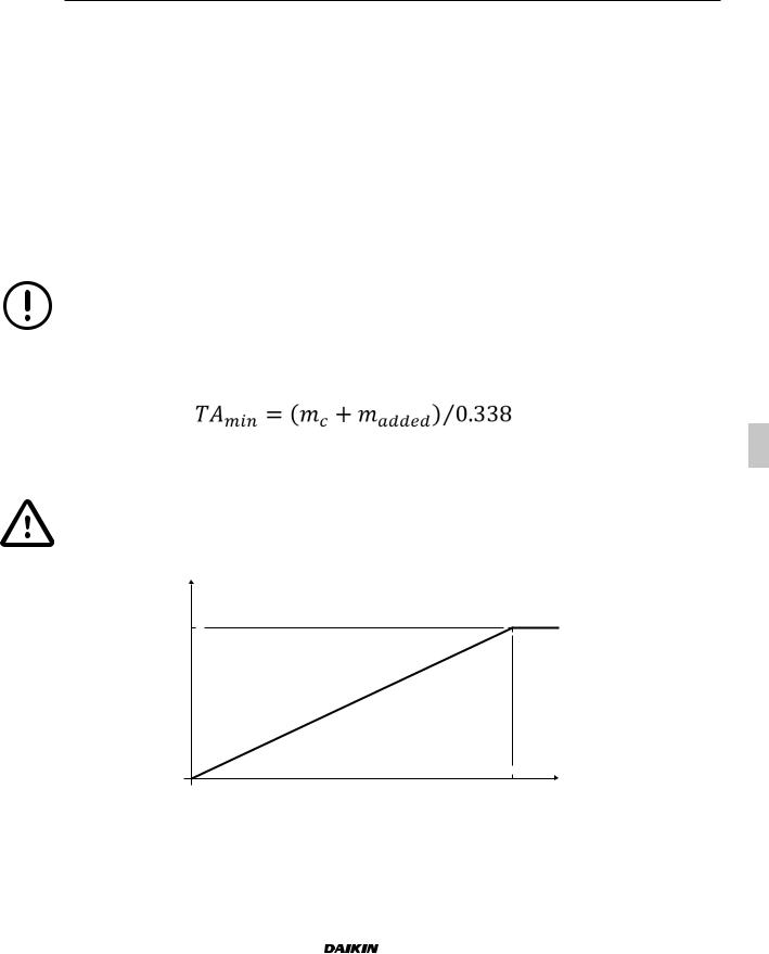
2.2.1 Limits to the use – Minimum area of the conditioned space and maximum refrigerant charge
Clause GG.9 of Annex GG within the standard IEC 60335-2-40:2018 (Household and similar electrical appliances - Safety - Part 2-40: Particular requirements for electrical heat pumps, air-conditioners and dehumidifiers) defines the charge limits based on the total conditioned space area and the ventilation requirements for ducted appliances using A2L refrigerants. For full details refer to the standard IEC 60335-2-40:2018.
The minimum total conditioned room area |
"TAmin" of installed appliance with refrigerant charge "mc" (kg) shall be in |
||||||||
accordance with following: |
|
|
|
|
|
|
|
|
|
|
|
|
|
|
|
|
|||
|
For units without hot gas post heating coil |
For units with hot gas post heating coil |
|||||||
Unit |
|
mc |
|
TAmin |
mc |
|
TAmin |
||
|
[kg] |
|
m2 |
[kg] |
|
m2 |
|||
|
|
|
|
||||||
|
Circuit 1 |
|
Circuit 2 |
|
Circuit 1 |
|
Circuit 2 |
||
|
|
|
|
|
|
||||
UATYA25 |
7 |
|
- |
|
20,7 |
8,3 |
|
- |
24,4 |
UATYA30 |
10 |
|
- |
|
29,6 |
11,3 |
|
- |
33,5 |
UATYA40 |
12 |
|
- |
|
35,5 |
13,7 |
|
- |
40,6 |
UATYA50 |
15 |
|
- |
|
44,4 |
17 |
|
- |
50,4 |
UATYA60 |
18 |
|
- |
|
53,3 |
21 |
|
- |
62 |
UATYA70 |
18 |
|
- |
|
53,3 |
21 |
|
- |
62 |
UATYA80 |
23 |
|
- |
|
68,1 |
26,9 |
|
- |
79,6 |
UATYA90 |
24 |
|
- |
|
71,1 |
28 |
|
- |
83 |
UATYA100 |
28 |
|
- |
|
82,9 |
32,3 |
|
- |
95,7 |
UATYA110 |
30 |
|
- |
|
88,8 |
34,7 |
|
- |
102,8 |
UATYA120 |
36 |
|
- |
|
106,6 |
41,2 |
|
- |
122,1 |
UATYA140 |
19 |
|
19 |
|
56,3 |
23,1 |
|
23,1 |
68,4 |
UATYA150 |
19 |
|
19 |
|
56,3 |
23,1 |
|
23,1 |
68,4 |
UATYA160 |
23 |
|
23 |
|
68,1 |
27,9 |
|
27,9 |
82,6 |
UATYA180 |
25 |
|
25 |
|
74 |
25 |
|
25 |
74 |
UATYA190 |
25 |
|
25 |
|
74 |
25 |
|
25 |
74 |
No zoning dampers shall be installed in the rooms considered to determine the minimum room area unless these zoning dampers can be fully opened by the control signal of the rooftop in case of a leak
If the refrigerant charge is adjusted on the field, the minimum area must be re-evaluated in order to be always above the result obtained through the following formula:
where
- madded is the refrigerant charge added on the field in kg.
The sum “mc+madded" must be lower than 79,8 kg for each circuit.
The minimum area according to the area of the conditioned space is shown below
|
90 |
|
|
|
|
|
|
80 |
|
|
|
|
|
| <![if ! IE]> <![endif]>[kg] |
70 |
|
|
|
|
|
60 |
|
|
|
|
|
|
| <![if ! IE]> <![endif]>mc |
|
|
|
|
|
|
50 |
|
|
|
|
|
|
|
|
|
|
|
|
|
|
40 |
|
|
|
|
|
|
30 |
|
|
|
|
|
|
20 |
|
|
|
|
|
|
10 |
|
|
|
|
|
|
0 |
|
|
|
|
|
|
0 |
50 |
100 |
150 |
200 |
250 |
|
|
|
|
[m²] |
|
|
Fig. 1 Total min. installation area
We reserve the right to make changes without any prior notice. |
Translation from original instructions |
UATYA |
Packaged Rooftop |
4P645202-1 |
13 |
|
The unit is equipped with a refrigerant detection system that complies with Annex LL of the IEC 60335-2-40:2018, which position has been checked according to test reported in Annex MM of IEC 60335-2-40:2018.
When the refrigerant detection system detects a leak, the following will be initiated by the unit:
•disable the compressor operation unless the compressors;
•Supply and return (if present) fan control will be set to to constant airflow logic with a fix airflow value. The fans
will operate continuously even if time tables are set. This in order to not let the airflow to go below "Qmin" (see below);
•Energize a dedicated relay in the electrical cabinet in order to fully open any external zoning dampers;
•Set the dampers (if installed on the appliance) in order to have a full intake of fresh air and a full expulsion of the return air.
External zoning dampers, if present, must be connected to this relay in order to be open when a leak is detected
Zoning dampers installed in rooms considered to determine the minimum room area must be electrically powered at all times after installation, other than when servicing, to be effective for safety.
The refrigerant detection system and controls will maintain the above action until at least 5 min after the refrigerant detection system has reset. Building fire and smoke systems may override this function.
If the leak detector detects a leak, the above operations will be initiated even if the unit is turned OFF by button, by BMS or by digital input.
In addition to what above another dedicated relay is present in the unit electrical cabinet and connected directly to the leak detector alarm. This relay can be used to monitor the leak detector alarm even in case of a unit control board fault.
The minimum circulation airflow (Qmin) circulated to the total conditioned space, expressed in m3⁄h, must be in accordance with the following table:
|
|
Unit |
For units without hot gas post heating coil |
For units with hot gas post heating coil |
||||||
|
|
mc |
|
Qmin |
mc |
|
Qmin |
|||
|
|
|
[kg] |
|
m3/h |
[kg] |
|
m3/h |
||
|
|
UATYA25 |
7 |
|
- |
1368 |
8,3 |
|
- |
1613 |
|
||||||||||
|
|
UATYA30 |
10 |
|
- |
1954 |
11,3 |
|
- |
2208 |
|
|
UATYA40 |
12 |
|
- |
2345 |
13,7 |
|
- |
2680 |
|
|
UATYA50 |
15 |
|
- |
2932 |
17 |
|
- |
3326 |
|
|
UATYA60 |
18 |
|
- |
3518 |
21 |
|
- |
4095 |
|
|
UATYA70 |
18 |
|
- |
3518 |
21 |
|
- |
4095 |
|
|
UATYA80 |
23 |
|
- |
4495 |
26,9 |
|
- |
5255 |
|
|
UATYA90 |
24 |
|
- |
4691 |
28 |
|
- |
5479 |
|
|
UATYA100 |
28 |
|
- |
5472 |
32,3 |
|
- |
6315 |
|
|
UATYA110 |
30 |
|
- |
5863 |
34,7 |
|
- |
6783 |
|
|
UATYA120 |
36 |
|
- |
7036 |
41,2 |
|
- |
8059 |
|
|
UATYA140 |
19 |
|
19 |
3713 |
23,1 |
|
23,1 |
4515 |
|
|
UATYA150 |
19 |
|
19 |
3713 |
23,1 |
|
23,1 |
4515 |
|
|
UATYA160 |
23 |
|
23 |
4495 |
27,9 |
|
27,9 |
5453 |
|
|
UATYA180 |
25 |
|
25 |
4886 |
25 |
|
25 |
4886 |
|
|
UATYA190 |
25 |
|
25 |
4886 |
25 |
|
25 |
4886 |
Whenever the flow, measured by the differantial air presssure tranducer, falls below the values reported in the table above, the airflow alarm from differential pressure transducer will be displayed on the unit control and the unit will be stopped.
The supply and return air shall be directly ducted to the conditioned space. Open areas such as false ceilings shall not be used as a return air duct.
Translation from original instructions |
We reserve the right to make changes without any prior notice. |
Packaged Rooftop |
UATYA |
14 |
4P645202-1 |
|

2.2.2Refrigerant leak detector
This unit is equipped with a refrigerant leak detector for safety.
To be effective, the unit must be electrically powered at all times after installation, other than when servicing.
A refrigerant leak detector is installed in the unit between the supply coil and the supply fan(s).
This device allows immediate detection of refrigerant leaks in order to start what reported in the above paragraph “Limit to the use – This device allows immediate detection of refrigerant leaks in order to start what reported in the above paragraph “Limit to the use – Minimum area required and maximum refrigerant charge”.
The detector has an internal self-testing routine. If this routine detects a fault the unit control will automatically modify the supply and return (if present) fan control in order to set a constant airflow
logic with a fix airflow value. This in order to not let the airflow to go below Qmin as defined in the paragraph "Limit to the use – Minimum area required and maximum refrigerant charge”. The fans will
operate continuously even if time tables are set, in order to have always the minimum required airflow.
In the unlike event that the airflow is not able to reach the minimum airflow level "Qmin and the leak detector is faulty, a dedicated relay in the electrical cabinet will be energized. This signal must be used to warn the user that the airflow is reduced (e.g. a buzzer and a flashing light).
Once the gas alarm of the leak detector system is released, the output is not reset even if the gas concentration decreases. After detecting and repairing the leak spot, a manual reset of the alarm can be operated. To reset the alarm output turn the power supply to the gas sensor off and on (e.g. disconnecting and reconnecting its cable), if the alarm output will not be reset after this operation, it means that leak has exceeded 10000 ppm, and the gas sensor has to be replaced.
The gas sensing part of the sensor has a designed life of 10 years. A countdown is set inside the detector control and read by the unit control.
Six months before the expire of the countdown a warning message will appear on the unit HMI. If the calibration will not be performed in time a warning message will appear on the unit HMI and the unit control will operate as in case of a leak detector fault (see first informative point of this paragraph).
We reserve the right to make changes without any prior notice. |
Translation from original instructions |
UATYA |
Packaged Rooftop |
4P645202-1 |
15 |
|

2.2.3Water flow rate at the heat exchangers
It is necessary to ensure that the water flow rate during operation is no higher than 1.5 times and no lower than 0.5 times the nominal flow rate of the unit stated in the Technical Catalogue.
In any case, refer to the specific Technical Catalogue for the allowed conditions for water flow in and out of the exchangers.
2.2.4 Water composition
Dissolved substances in the water can cause corrosion in the heat exchangers.
It is mandatory to make sure the parameters of the water comply with the following table:
Description |
Values |
Total hardness |
2,0 ÷ 6,0 °f |
Langelier index |
- 0,4 ÷ 0,4 |
pH |
7,5 ÷ 8,5 |
Electrical conductivity |
10÷500 µS/cm |
Organic elements |
- |
Hydrogen carbonate (HCO3-) |
70 ÷ 300 ppm |
Sulphates (SO42-) |
< 50 ppm |
Hydrogen carbonate / Sulphates (HCO3-/SO42-) |
> 1 |
Chlorides (Cl-) |
< 50 ppm |
Nitrates (NO3-) |
< 50 ppm |
Hydrogen sulphide (H2S) |
< 0,05 ppm |
Ammonia (NH3) |
< 0,05 ppm |
Sulphites (SO3), free chlorine (Cl2) |
< 1 ppm |
Carbon dioxide (CO2) |
< 5 ppm |
Metal cations |
< 0,2 ppm |
Manganese ions (Mn++) |
< 0,2 ppm |
Iron ions (Fe2+, Fe3+) |
< 0,2 ppm |
Iron + Manganese |
< 0,4 ppm |
Phosphates (PO43-) |
< 2 ppm |
Oxygen |
< 0,1 ppm |
ppm = mg/l
The use of water with values above the limits stated in the table will immediately void the warranty.
It is mandatory to include a system for eliminating possible organic substances in the water that could pass through the filter and settle in the heat exchangers, which would lead to malfunctioning and/or breakage over time.
The use of water containing organic substances will immediately void the warranty.
Translation from original instructions |
We reserve the right to make changes without any prior notice. |
Packaged Rooftop |
UATYA |
16 |
4P645202-1 |
|

2.2.5Warnings concerning flammable refrigerants
Units with mildly flammable refrigerants (A2L), such as R32, shall be installed in accordance with the
European standards and regulations and with the local regulations, where applicable.
The information below is provided in accordance with standard IEC 60335-2-40:2018 and its annexes and clauses (here in after “Annex” and “Clause”) and it has been taken from the English version of the standard, which is the document to be referenced.
(Annex DD.2) Do not use means to accelerate the defrosting process or to clean, other than those recommended by the manufacturer.
The external unit shall be stored in a room without continuously operating ignition sources (for example: open flames, an operating gas appliance or an operating electric heater).
Do not pierce or burn.
Be aware that refrigerants may not contain an odour.
 (Annex DD.3.3) Qualification of workers
Any operation concerning the installation, maintenance, repair, disassembly and dismantling of the unit shall be carried out by qualified personnel, in accordance withAnnex HH to standard IEC 60335-2-40:2018, who hold a valid certificate in compliance with the existing standards.
The above-mentioned operations include:
•breaking into the refrigerating circuit;
•opening of sealed components;
•opening of ventilated enclosures.
 (Annex DD.4) Information on servicing
 (Annex DD.4.2) Checks to the area
Prior to beginning work on systems containing flammable refrigerants, safety checks in the area are necessary to ensure that the risk of ignition is minimised. For repair to the refrigerating system, DD.4.3 to DD.4.7 shall be completed prior to conducting work on the system.
We reserve the right to make changes without any prior notice. |
Translation from original instructions |
UATYA |
Packaged Rooftop |
4P645202-1 |
17 |
|

Prior to beginning work on systems containing flammable refrigerants, safety checks in the area are necessary to ensure that the risk of ignition is minimised. For repair to the refrigerating system, DD.4.3 to DD.4.7 shall be completed prior to conducting work on the system.
 (Annex DD.4.3) Work procedure
Work shall be undertaken under a controlled procedure so as to minimise the risk of a flammable gas or vapour being present while the work is being performed.
 (Annex DD.4.4) General work area
All maintenance staff and others working in the local area shall be instructed on the nature of the work being carried out. Work in confined spaces shall be avoided.
 (Annex DD.4.5) Checking for presence of refrigerant
The area shall be checked with an appropriate refrigerant detector prior to and during work, to ensure the technician is aware of potentially toxic and flammable atmospheres.
Ensure that the refrigerant or leak detection equipment being used is suitable for use with the refrigerant applicable to the unit, i.e. non-sparking, adequately sealed or intrinsically safe.
 (Annex DD.4.6) Presence of fire extinguisher
Ifanyhotworkistobeconductedontheunitrequiringanincreaseinthetemperatureofpartsoftheunit(e.g.brazing), appropriate fire extinguishing equipment shall be available to hand. Have a dry powder or CO2 fire extinguisher adjacent to the refrigerant charging area.
 (Annex DD.4.7) No ignition sources
No person carrying out work in relation to a unit shall use any sources of ignition in such a manner that it may lead to the risk of fire or explosion. All possible ignition sources, including cigarette smoking, should be kept sufficiently far away from the site of installation, repairing, removing and disposal of the unit, during which flammable refrigerant can possibly be released to the surrounding space. Prior to work taking place, the area around the unit is to be surveyed to make sure that there are no flammable hazards or ignition risks. “No Smoking” signs shall be displayed.
Translation from original instructions |
We reserve the right to make changes without any prior notice. |
Packaged Rooftop |
UATYA |
18 |
4P645202-1 |
|

 (Annex DD.4.8) Ventilated area
Ensure that the area is in the open or that it is adequately ventilated before breaking into the system or conducting any hot work. A degree of ventilation shall continue during the period that the work is carried out. The ventilation should safely disperse any released refrigerant and preferably expel it externally into the atmosphere.
 (Annex DD.4.9) Checks to the refrigerating equipment
Whereelectricalcomponentsarebeingchanged,theyshallbefitforthepurposeandtothecorrectspecification.Atall times the manufacturer’s maintenance and service guidelines shall be followed. If in doubt consult the manufacturer’s technical department for assistance.
The following checks shall be applied to installations using flammable refrigerants (some parts are only applicable to refrigerant containing units or components installed inside the building):
•the charge size is in accordance with the room size within which the refrigerant containing parts are installed;
•the ventilation machinery and outlets are operating adequately and are not obstructed;
•marking to the unit and components continues to be visible and legible. Markings and signs that are illegible shall be corrected;
•refrigeration pipe or refrigerant containing components are installed in a position where they are unlikely to be exposed to any substance which may corrode refrigerant containing components, unless the components are constructed of materials which are inherently resistant to being corroded or are suitably protected against being so corroded.
 (Annex DD.4.10) Checks to electrical components
Repair and maintenance to electrical components shall include initial safety checks and component inspection procedures. If a fault exists that could compromise safety, then no electrical supply shall be connected to the circuit until it is satisfactorily dealt with. If the fault cannot be corrected immediately but it is necessary to continue operation, an adequate temporary solution shall be used. This shall be reported to the owner of the unit so all parties are advised.
Initial safety checks shall include:
•that capacitors are discharged: this shall be done in a safe manner to avoid possibility of sparking;
•that no live electrical components and wiring are exposed while charging, recovering or purging the system;
•that there is continuity of earth bonding.
 (Annex DD.5) Repairs to sealed components
 (Annex DD.5.1)
During repairs to sealed components, all electrical supplies shall be disconnected from the unit being worked upon prior to any removal of sealed covers, guards, etc.
If it is absolutely necessary to have an electrical supply to the unit during servicing, then a permanently operating form of refrigerant leak detection shall be located at the most critical point to warn of a potentially hazardous situation.
We reserve the right to make changes without any prior notice. |
Translation from original instructions |
UATYA |
Packaged Rooftop |
4P645202-1 |
19 |
|

 (Annex DD.5.2)
Particular attention shall be paid to the following to ensure that by working on electrical components, the casing is not altered in such a way that the level of protection is affected.
This shall include damage to cables, excessive number of connections, terminals not made to original specification, damage to seals, incorrect fitting of glands, etc.
Ensure that apparatus is mounted securely.
Ensure that seals or sealing materials have not degraded such that they no longer serve the purpose of preventing the ingress of flammable atmospheres. Replacement parts shall be in accordance with the manufacturer’s specifications.
 (Annex DD.5) Repairs to intrinsically safe components
Do not apply any permanent inductive or capacitance loads to the circuit without ensuring that this will not exceed the permissible voltage and current permitted for the equipment in use.
Intrinsically safe components are the only types that can be worked on while live in the presence of a flammable atmosphere. The test apparatus shall be at the correct rating.
Replace components only with parts specified by the manufacturer. Other parts may result in the ignition of refrigerant in the atmosphere from a leak.
 (Annex DD.7) Cabling
Check that cabling will not be subject to wear, corrosion, excessive pressure, vibration, sharp edges or any other adverse environmental effects.The check shall also take into account the effects of ageing or continual vibration from sources such as compressors or fans.
 (Annex DD.8) Detection of flammable refrigerants
Under no circumstances shall potential sources of ignition be used in the searching for or detection of refrigerant leaks. A halide torch (or any other detector using a naked flame) shall not be used.
The following leak detection methods are deemed acceptable for systems containing flammable refrigerants.
Electronic leak detectors shall be used to detect flammable refrigerants, but the sensitivity may not be adequate, or may need re-calibration (detection equipment shall be calibrated in a refrigerant-free area). Ensure that the detector is not a potential source of ignition and is suitable for the refrigerant used.The leak detection system shall be set at a percentage of the refrigerant LFL and it shall be calibrated to the refrigerant employed; the appropriate percentage of gas (25% maximum) shall be confirmed.
Leak detection fluids are suitable for use with most refrigerants but the use of detergents containing chlorine shall be avoided as the chlorine may react with the refrigerant and corrode the copper pipe-work.
Note. Examples of leak detection fluids are:
•bubble method;
•fluorescent method agents.
If a leak is suspected, all naked flames shall be removed/extinguished.
If a leakage of refrigerant is found which requires brazing, all of the refrigerant shall be recovered from the system, or isolated (by means of shut off valves) in a part of the system remote from the leak. Removal of refrigerant shall be according to Annex DD.9.
Translation from original instructions |
We reserve the right to make changes without any prior notice. |
Packaged Rooftop |
UATYA |
20 |
4P645202-1 |
|
 (Annex DD.9) Removal and evacuation
When breaking into the refrigerant circuit to make repairs – or for any other purpose – conventional procedures shall be used. However, it is important that best practice is followed since flammability is a consideration.
The following procedure shall be adhered to:
•remove refrigerant;
•purge the circuit with inert gas (optional for A2L);
•evacuate (optional for A2L);
•open the circuit by cutting or brazing.
The refrigerant charge shall be recovered into the correct recovery cylinders. For units containing flammable refrigerants other thanA2L the system shall be “flushed” with OFN to render the unit safe. This process may need to be repeated several times. Compressed air or oxygen shall not be used for purging refrigerant systems.
For units containing flammable refrigerants, other than A2L refrigerants, refrigerants purging shall be achieved by breaking the vacuum in the system with oxygen-free nitrogen and continuing to fill until the working pressure is achieved, then venting to atmosphere, and finally pulling down to a vacuum. This process shall be repeated until no refrigerant is within the system. When the final oxygen-free nitrogen charge is used, the system shall be vented down to atmospheric pressure to enable work to take place. This operation is absolutely vital if brazing operations on the pipe-work are to take place.
 (Annex DD.10) Charging procedures
In addition to conventional charging procedures, the following requirements shall be followed.
•Ensure that contamination of different refrigerants does not occur when using charging equipment. Hoses or lines shall be as short as possible to minimise the amount of refrigerant contained in them.
•Cylinders shall be kept in an appropriate position according to the instructions.
•Ensure that the refrigerating system is earthed prior to charging the system with refrigerant.
•Label the system when charging is complete (if not already).
•Extreme care shall be taken not to overfill the refrigerating system.
Prior to recharging the system it shall be pressure-tested with the appropriate purging gas. The system shall be leaktested on completion of charging but prior to commissioning. A follow up leak test shall be carried out prior to leaving the site.
 (Annex DD.11) Decommissioning
Before carrying out this procedure, it is essential that the technician is completely familiar with the unit and all its detail. It is recommended good practice that all refrigerants are recovered safely. Prior to the task being carried out, an oil and refrigerant sample shall be taken in case analysis is required prior to re-use of reclaimed refrigerant.
a)Become familiar with the equipment and its operation.
b)Isolate system electrically.
c)Before attempting the procedure, ensure that:
•mechanical handling equipment is available, if required, for handling refrigerant cylinders;
•all personal protective equipment is available and being used correctly;
•the recovery process is supervised at all times by a competent person;
•Label the system when charging is complete (if not already).
•recovery equipment and cylinders conform to the appropriate standards.
We reserve the right to make changes without any prior notice. |
Translation from original instructions |
UATYA |
Packaged Rooftop |
4P645202-1 |
21 |
|

d)Pump down refrigerant system, if possible.
e)If a vacuum is not possible, make a manifold so that refrigerant can be removed from various parts of the system.
f)Make sure that cylinder is situated on the scales before recovery takes place.
g)Start the recovery machine and operate in accordance with instructions.
h)Do not overfill cylinders (no more than 80 % volume liquid charge).
i)Do not exceed the maximum working pressure of the cylinder, even temporarily.
j)When the cylinders have been filled correctly and the process completed, make sure that the cylinders and the equipment are removed from site promptly and all isolation valves on the equipment are closed off.
k)Recovered refrigerant shall not be charged into another refrigerating system unless it has been cleaned and checked.
 (Annex DD.12) Labelling
Equipment shall be labelled stating that it has been de-commissioned and emptied of refrigerant. The label shall be dated and signed. For appliances containing flammable refrigerants, ensure that there are labels on the equipment stating the equipment contains flammable refrigerant.
 (Annex DD.13) Recovery
When removing refrigerant from a system, either for servicing or decommissioning, it is recommended good practice that all refrigerants are removed safely.
When transferring refrigerant into cylinders, ensure that only appropriate refrigerant recovery cylinders are employed. Ensure that the correct number of cylinders for holding the total system charge are available. All cylinders to be used are designated for the recovered refrigerant and labelled for that refrigerant (i.e. special cylinders for the recovery of refrigerant). Cylinders shall be complete with pressure-relief valve and associated shut-off valves in good working order. Empty recovery cylinders are evacuated and, if possible, cooled before recovery occurs.
The recovery equipment shall be in good working order with a set of instructions concerning the equipment that is at hand and shall be suitable for the recovery of flammable refrigerants. In addition, a set of calibrated weighing scales shall be available and in good working order. Hoses shall be complete with leak-free disconnect couplings and in good condition. Before using the recovery machine, check that it is in satisfactory working order, has been properly maintained and that any associated electrical components are sealed to prevent ignition in the event of a refrigerant release. Consult manufacturer if in doubt.
The recovered refrigerant shall be returned to the refrigerant supplier in the correct recovery cylinder, and the relevant waste transfer note arranged. Do not mix refrigerants in recovery units and especially not in cylinders.
If compressors or compressor oils are to be removed, ensure that they have been evacuated to an acceptable level to make certain that flammable refrigerant does not remain within the lubricant. The evacuation process shall be carried out prior to returning the compressor to the suppliers. Only electric heating to the compressor body shall be employed to accelerate this process.
When oil is drained from a system, it shall be carried out safely.
Translation from original instructions |
We reserve the right to make changes without any prior notice. |
Packaged Rooftop |
UATYA |
22 |
4P645202-1 |
|

2.3Noise
The starting of the unit, with activation of its components, emits a noise whose intensity varies depending on the operating level.
The correct location choice and the correct installation prevent the unit causing annoying noise due to resonances, reflections and vibrations.
2.4Residual risks
The unit uses technical means suitable for protecting people, animals and things against hazards that cannot reasonably be eliminated or sufficiently reduced through design.
The presence of an operator is not required for normal operation of the unit. The change from the "OFF" state to the "ON" state, and vice versa, of the unit can be carried out remotely or through the display, without having to enter areas at risk.
Access restriction is part of correct installation to eliminate residual risks during normal operation.
Removal of the restrictions gives access to cold parts, hot parts and sharp edges.
When the electrical boxes and the electrical control panel are open, live parts can be accessed.
Instrument connection to the refrigerant circuit may cause the release of mildly flammable refrigerant.
Do not:
-remove or disable the safety guards;
-tamper with and/or modify, even partially, the safety devices installed on the unit.
In heat pump operation, during defrost cycles, the water drips onto the ground when the frost melts off the coils.
If the water is not properly drained, when the ambient temperatures are sub-zero, dangerous sheets of ice are formed. Limit access to the area to prevent accidents.
We reserve the right to make changes without any prior notice. |
Translation from original instructions |
|
|
UATYA |
Packaged Rooftop |
4P645202-1 |
23 |
|
2.5Safety information on the refrigerant fluid
This product contains fluorinated greenhouse gases included in the Kyoto protocol. Do not release these gases into the atmosphere.
Type of refrigerant: R32.
GWP value: 677. Based on "IPCC Fifth Assessment Report". GWP is the global warming potential.
The quantity of refrigerant fluid is indicated in the unit’s data label. Periodic inspections are necessary to check for refrigerant fluid leaks in accordance with local and/or European regulations.
2.5.1Hazards and health consequences
If accidentally released, rapid evaporation of the liquid can cause freezing.
In case of contact with the liquid:
-defrost the various part with water;
-remove clothing carefully;
-rinse thoroughly with water.
Contaminated clothing and shoes should be washed before reuse.
High vapour concentrations can cause headaches, dizziness, drowsiness and nausea, and may lead to unconsciousness and cardiac arrhythmia.
Ifinhaled move the victim to fresh air.Artificial respiration and/or oxygen may be necessary. Call a doctor immediately.
In case of contact with eyes, remove contact lenses. Rinse immediately with plenty of water, holding the eyelids open, for at least 15 minutes.
The safety data sheet drawn up by the producer of the refrigerant can be obtained from the manufacturer of the unit.
The refrigerants used in these units are classified as ASHRAE A2L and they are characterised by low flammability (burning velocity < 10 cm/s). If refrigerant leaks out, it tends to stagnate in the bottom part of the area where the leak has occurred.
|
Translation from original instructions |
We reserve the right to make changes without any prior notice. |
|
Packaged Rooftop |
UATYA |
24 |
4P645202-1 |
|
3 RECEIVING THE PRODUCT AND STORAGE
3.1Reception
On receiving the unit, check that it is undamaged, bearing in mind that it left the factory in perfect condition.
Report any signs of damage immediately to the transporter and make a note of these on the Delivery Sheet before signing it.
The relevant sales department or the manufacturer should be informed of the extent of the damage as soon as possible.
The Customer must draw up a written and photographic report concerning any and all significant damage.
Disposal of the packing material is the responsibility of the consignee and must be carried out in compliance with the regulations in force in the country in which it is carried out.
3.2Transport
The unit is sent from the factory using suitable vehicles, with correct locking in order to prevent any possibility of movement whilst in transit by road that may damage it or cause accidents.
If there is to be trans-shipment to other vehicles to continue the journey, it is essential to adopt all necessary measures for ensuring the correct safety conditions, with regard to the vehicles used and the anchorage, in order to prevent damage.
If the unit is to be transported over uneven roads, the manufacturer must be informed beforehand so that suitable measures can be taken in order to prevent damage to the unit.
If it is to be transported by container, make sure it is correctly anchored.
With reference to road, sea/ocean or air freight, refer to the ADR, IMDG, IATA codes, etc. in place at the time of transport.
Before organising the freight, the Manufacturer shall notify the quantity and type of refrigerant filled in the machine.
Units with mildly flammable refrigerants (A2L) shall be hauled in accordance with the European standards and regulations and the local regulations, where applicable.
We reserve the right to make changes without any prior notice. |
Translation from original instructions |
|
|
UATYA |
Packaged Rooftop |
4P645202-1 |
25 |
|

3.3Handling
Before each unit handling operation, check that the lifting capacity of the machinery used is compatible with the weight of the unit.
Handling must be carried out by adequately equipped qualified personnel.
In all lifting operations, make sure the unit is firmly secured in order to prevent accidental falls or overturning.
Lifting must be carried out by qualified and authorised personnel taking the necessary precautions; if carried out incorrectly, lifting can cause serious damage and physical injury.
The handling operations must be carried out slowly and sudden manoeuvres and knocks must be avoided.
Do not, under any circumstances, stand or pass under or near the unit when it is lifted off the ground.
Use only the lifting system designed and prepared for the unit.
During unloading and positioning of the unit, great care must be taken to prevent sudden or violent manoeuvres, and the components of the unit must not be used as lifting points.
Make sure the machinery and lifting ropes are of suitable size and capacity and strictly follow their operating instructions. Use only equipment that is in excellent working order.
Check that the lifting equipment is of suitable size and capacity and strictly follow its operating instructions. Use only equipment that is in excellent working order.
All work on the unit, including unpacking and connections, must be carried out with the unit resting on the ground. Refer, in any case, to the lifting instructions provided with the unit.
A pallet is secured under the unit so that it can also be unloaded and handled with a suitable forklift truck.
If anti-vibration mounts are installed under the base of the unit, this must be done with the unit raised by no more than 200 mm from the ground and without putting any parts of the body under it.
Before sliding out the pallet, remove the screws fixing it to the unit.
Use a 10 mm spanner to unscrew the screws that are visible through the slotted holes of the base.
Once the pallet has been removed, the unit must be lifted using only and exclusively slings and the yellow lifting brackets fixed to the base.
Use suitable shackles to fasten the slings to the lifting brackets.
Fig. 2 Focus on the attachment of the sling to the lifting bracket
Translation from original instructions |
We reserve the right to make changes without any prior notice. |
Packaged Rooftop |
UATYA |
26 |
4P645202-1 |
|

For lifting use all the brackets present in the unit.
Fig. 3 Lifting with slings
To prevent the slings from touching the unit, suitable protective devices must be placed on the upper edges.
It is mandatory to use a lifting beam adjusted to the width of the unit in order to ensure lifting stability
We reserve the right to make changes without any prior notice. |
Translation from original instructions |
|
|
||
UATYA |
Packaged Rooftop |
|
4P645202-1 |
27 |
|
|
|

4 PRODUCT DESCRIPTION
4.1Intended use
These units are intended for air cooling / heating, generally used in air conditioning applications
These are high efficiency, self-contained air conditioners, for both summer and winter use, that allow attainment of complete thermo-hygrometric air handling and recovery of the heat dispersed for air renewal. They can be used in both commercial and industrial applications that, besides having load variability, can be characterized by high latent loads and need to guarantee optimum conditions for occupants.
Their use is recommended within the operating limits indicated in the Technical Catalogue.
4.2Unintended use
The unit must not be used:
-in an explosive atmosphere;
-in a flammable atmosphere;
-in extremely dusty environments;
-in an environment that is not compatible with the stated IP protection rating;
-by untrained personnel;
-in a way that does not comply with the regulations in force;
-with incorrect installation;
-with power supply defects;
-with total or partial failure to comply with the instructions;
-with lack of maintenance and/or use of non-original spare parts;
-with inefficient safety components.
-with modifications or other work not authorised by the Manufacturer.
|
Translation from original instructions |
We reserve the right to make changes without any prior notice. |
|
Packaged Rooftop |
UATYA |
28 |
4P645202-1 |
|

4.3Control and safety devices
The unit is integrally managed by an electronic microprocessor control that, through the various installed temperature and pressure sensors, keeps its operation within the safety limits.
All the parameters involved with control of the unit are shown in the “Control Manual” that is an integral part of the documentation of the unit.
All the parameters involved with control of the unit are shown in the “Operating Manual” that is an integral part of the documentation of the unit.
The manual fully describes the logic with which the checks of the unit take place during the various operating stages. The control and safety devices are shown in the Technical Catalogue.
4.4Principles of operation
The basic operation of these units uses a reverse vapour compression cycle to change the thermo-hygrometric conditions of the air in the interior environment. The simplest configuration works in total air recirculation.
The refrigeration cycle allows heat to be transferred from a fluid at a lower temperature to a fluid at a higher temperature. The Roof Top units are equipped with one or more refrigerant circuits; in cooling mode, air is cooled - and if necessary dehumidified - by a finned coil (evaporator); the removed heat is rejected to the outside by another finned coil (condenser).
In addition to this, the heat pump versions allow the evaporator and condenser roles to be reversed, thereby providing the heating function.
In addition to air filtration, other functions are possible, which vary depending on the configuration and the selected accessories: partial air renewal, heat recovery from expelled air, thermodynamic recovery, humidification, additional heating by means of burner, battery with hot water or electric heaters, free cooling / free heating.
4.5Structure
Depending on the sizes, the structure is made of galvanized sheet-iron coated with epoxy polyester powder at 180°C, which makes it highly resistant to weather conditions, or of extruded aluminium alloy profiles connected with glass fibre reinforced nylon joints.
The base and cover are made of thick, epoxy polyester powder coated, galvanized sheet-iron.
The panelling is made with 25mm thick sandwich panels consisting of a 0.5 mm thick externally pre-painted galvanizedsheet-ironcasingfilledwithpolyurethanefoamtoguaranteethethermalandacousticinsulationoftheunit.
Alternatively, the panels are insulated with closed-cell insulating matting or with rock wool, for the "heat generator" section. The surface of the panels in contact with the treated air is made of galvanized sheet-iron to facilitate cleaning and sanitizing operations.
The non-removable panels are fixed to the structure with screws contained in nylon bushes with plug.
The removable panels are attached to the structure with nylon eccentrics or inserts and have handles to make them easier to remove.
4.6Specifications
Direct expansion air conditioner with hermetic compressors, evaporating coil with centrifugal or radial fans and condensing coil with axial fans.
The unit is made in two sections that are joined together but functionally separate. One section is for transferring the energy absorbed from the treated interior environment into the atmosphere. The other section is for air handling and allows air conditioning of the confined environment to be treated.
In configurations where air exchange is envisaged, heat recovery and free cooling/free heating can be managed.
For heating, there may be a gas heat generator, or a hot water coil or a group of electric heaters.
We reserve the right to make changes without any prior notice. |
Translation from original instructions |
UATYA |
Packaged Rooftop |
4P645202-1 |
29 |
|

4.7Air system
4.7.1Internal air fans
Depending on the configurations, there may be only supply fans or also return fans in the units.
The fans are radial fans with reverse blades, with external rotor motor directly coupled to the impeller.
The radial fans are called "EC", with electronically commutated brushless motor. The fan is powered by mains AC voltage, and speed control is obtained via DC 0-10V control signal coming from the microprocessor installed on the unit. This makes it possible to set the air flow rate through the parameter being displayed.
The motors have alarm signalling, which includes thermal overload protection, overcurrent, undervoltage, absence of one or more phases and seized rotor.
The EC fans are not provided with a contactor and are constantly live as soon as the main disconnect switch of the unit is closed.
4.7.2Flow rate sensor for fans
Units with "EC" fans are provided with a differential pressure transducer that detects the pressure difference between the inside and the outside (upstream) of the intake nozzle. The air flow rate is proportional, for each fan/nozzle pair, to the square root of the pressure difference according to the equation:
where
-Q = total air flow [m3 / h]
-n = number of fans in the unit
-k = constant according to the fan nozzle
-ΔP = pressure difference measured on the nozzle [Pa]
The differential pressure value and the air flow rate can be shown directly on the display of the microprocessor that carries out automatic control of the air flow rate.
|
Translation from original instructions |
We reserve the right to make changes without any prior notice. |
|
Packaged Rooftop |
UATYA |
30 |
4P645202-1 |
|
 Loading...