


 Loading...
Daikin RXYQQ8U7Y1B*, RXYQQ10U7Y1B*, RXYQQ12U7Y1B*, RXYQQ14U7Y1B*, RXYQQ16U7Y1B* Installer reference guide
...Installer and user reference guide
VRV IV Q+ series heat pump
RXYQQ8U7Y1B*
RXYQQ10U7Y1B*
RXYQQ12U7Y1B*
RXYQQ14U7Y1B*
RXYQQ16U7Y1B*
RXYQQ18U7Y1B*
RXYQQ20U7Y1B*

Table of contents
Table of contents
1 |
About the documentation |
6 |
|
|||
|
|
1.1 |
About this document ...................................................................................................................................................... |
6 |
|
|
|
|
1.2 |
Meaning of warnings and symbols................................................................................................................................. |
7 |
|
|
2 |
General safety precautions |
9 |
|
|||
|
|
2.1 |
For the installer............................................................................................................................................................... |
9 |
|
|
|
|
|
2.1.1 |
General ........................................................................................................................................................... |
9 |
|
|
|
|
2.1.2 |
Installation site ............................................................................................................................................... |
10 |
|
|
|
|
2.1.3 |
Refrigerant — in case of R410A or R32 .......................................................................................................... |
10 |
|
|
|
|
2.1.4 |
Electrical ......................................................................................................................................................... |
12 |
|
3 |
Specific installer safety instructions |
15 |
||||
|
|
|
|
|||
|
For the user |
|
18 |
|||
4 |
User safety instructions |
19 |
||||
|
|
4.1 |
General |
............................................................................................................................................................................ |
19 |
|
|
|
4.2 |
Instructions .......................................................................................................................................for safe operation |
20 |
|
|
5 |
About the system |
23 |
||||
|
|
5.1 |
System layout.................................................................................................................................................................. |
23 |
|
|
6 |
User interface |
24 |
||||
7 |
Before operation |
25 |
||||
8 |
Operation |
|
27 |
|||
|
|
8.1 |
Operation ..............................................................................................................................................................range |
27 |
|
|
|
|
8.2 |
Operating .....................................................................................................................................................the system |
27 |
|
|
|
|
|
8.2.1 ........................................................................................................................... |
About operating the system |
27 |
|
|
|
|
8.2.2 ......................................................................... |
About cooling, heating, fan only, and automatic operation |
28 |
|
|
|
|
8.2.3 .......................................................................................................................... |
About the heating operation |
28 |
|
|
|
|
8.2.4 ...................................... |
To operate the system (WITHOUT cool/heat changeover remote control switch) |
29 |
|
|
|
|
8.2.5 ............................................. |
To operate the system (WITH cool/heat changeover remote control switch) |
29 |
|
|
|
8.3 |
Using the ....................................................................................................................................................dry program |
30 |
|
|
|
|
|
8.3.1 ................................................................................................................................... |
About the dry program |
30 |
|
|
|
|
8.3.2 .................................... |
To use the dry program (WITHOUT cool/heat changeover remote control switch) |
30 |
|
|
|
|
8.3.3 ........................................... |
To use the dry program (WITH cool/heat changeover remote control switch) |
30 |
|
|
|
8.4 |
Adjusting ......................................................................................................................................the air flow direction |
31 |
|
|
|
|
|
8.4.1 .................................................................................................................................... |
About the air flow flap |
31 |
|
|
|
8.5 |
Setting the ...................................................................................................................................master user interface |
32 |
|
|
|
|
|
8.5.1 ........................................................................................................ |
About setting the master user interface |
32 |
|
|
|
|
8.5.2 ................................................................. |
To designate the master user interface (VRV DX and Hydrobox) |
33 |
|
|
|
8.6 |
About control ....................................................................................................................................................systems |
33 |
|
|
9 |
Energy saving and optimum operation |
34 |
||||
|
|
9.1 |
Available ................................................................................................................................main operation methods |
34 |
|
|
|
|
9.2 |
Available ..............................................................................................................................................comfort settings |
35 |
|
|
10 |
Maintenance and service |
36 |
||||
|
|
10.1 |
Maintenance ............................................................................................................................after a long stop period |
36 |
|
|
|
|
10.2 |
Maintenance .........................................................................................................................before a long stop period |
37 |
|
|
|
|
10.3 |
About the ......................................................................................................................................................refrigerant |
37 |
|
|
|
|
10.4 |
After-sales ....................................................................................................................................service and warranty |
37 |
|
|
|
|
|
10.4.1 ............................................................................................................................................. |
Warranty period |
37 |
|
|
|
|
10.4.2 ................................................................................................ |
Recommended maintenance and inspection |
38 |
|
|
|
|
10.4.3 ..................................................................................... |
Recommended maintenance and inspection cycles |
38 |
|
|
|
|
10.4.4 ......................................................................................... |
Shortened maintenance and replacement cycles |
39 |
|
11 |
Troubleshooting |
40 |
||||
|
|
11.1 |
Error codes: ....................................................................................................................................................Overview |
41 |
|
|
|
|
11.2 |
Symptoms ...............................................................................................................that are NOT system malfunctions |
44 |
|
|
|
|
|
11.2.1 ....................................................................................................... |
Symptom: The system does not operate |
44 |
|
|
|
|
11.2.2 ............................................................................................. |
Symptom: Cool/Heat cannot be changed over |
44 |
|
|
|
|
11.2.3 ................................................ |
Symptom: Fan operation is possible, but cooling and heating do not work |
44 |
|
|
|
|
11.2.4 ...................................................................... |
Symptom: The fan speed does not correspond to the setting |
44 |
|
|
|
|
|
|
|
|
Installer and user reference guide |
|
|
|
RXYQQ8~20U7Y1B |
||
2 |
|
|
|
VRV IV Q+ series heat pump |
||
|
|
|
|
4P546229-1A – 2020.10 |
||

Table of contents
|
|
11.2.5 |
Symptom: The fan direction does not correspond to the setting................................................................. |
44 |
|
|
|
11.2.6 |
Symptom: White mist comes out of a unit (Indoor unit) .............................................................................. |
45 |
|
|
|
11.2.7 |
Symptom: White mist comes out of a unit (Indoor unit, outdoor unit)........................................................ |
45 |
|
|
|
11.2.8 |
Symptom: The user interface reads "U4" or "U5" and stops, but then restarts after a few minutes.......... |
45 |
|
|
|
11.2.9 |
Symptom: Noise of air conditioners (Indoor unit)......................................................................................... |
45 |
|
|
|
11.2.10 |
Symptom: Noise of air conditioners (Indoor unit, outdoor unit) .................................................................. |
45 |
|
|
|
11.2.11 |
Symptom: Noise of air conditioners (Outdoor unit)...................................................................................... |
45 |
|
|
|
11.2.12 |
Symptom: Dust comes out of the unit........................................................................................................... |
46 |
|
|
|
11.2.13 |
Symptom: The units can give off odours ....................................................................................................... |
46 |
|
|
|
11.2.14 |
Symptom: The outdoor unit fan does not spin.............................................................................................. |
46 |
|
|
|
11.2.15 |
Symptom: The display shows "88"................................................................................................................. |
46 |
|
|
|
11.2.16 |
Symptom: The compressor in the outdoor unit does not stop after a short heating operation ................. |
46 |
|
|
|
11.2.17 |
Symptom: The inside of an outdoor unit is warm even when the unit has stopped.................................... |
46 |
|
|
|
11.2.18 |
Symptom: Hot air can be felt when the indoor unit is stopped.................................................................... |
46 |
|
|
12 Relocation |
|
47 |
|
|
|
13 Disposal |
|
48 |
|
|
|
14 Technical data |
49 |
|
||
14.1 |
Information requirements for Eco Design...................................................................................................................... |
49 |
|
||
|
|
|
|
||
|
For the installer |
50 |
|
||
|
15 About the box |
51 |
|
||
15.1 |
About LOOP BY DAIKIN ................................................................................................................................................... |
51 |
|
||
15.2 |
Overview: About the box ................................................................................................................................................ |
51 |
|
||
15.3 |
To unpack the outdoor unit............................................................................................................................................ |
52 |
|
||
15.4 |
To remove the accessories from the outdoor unit ........................................................................................................ |
53 |
|
||
15.5 |
Accessory pipes: Diameters............................................................................................................................................ |
53 |
|
||
15.6 |
To remove the transportation stay ................................................................................................................................ |
54 |
|
||
|
16 About the units and options |
55 |
|
||
16.1 |
Overview: About the units and options.......................................................................................................................... |
55 |
|
||
16.2 |
Identification label: Outdoor unit................................................................................................................................... |
55 |
|
||
16.3 |
About the outdoor unit................................................................................................................................................... |
56 |
|
||
16.4 |
System layout.................................................................................................................................................................. |
56 |
|
||
16.5 |
Combining units and options.......................................................................................................................................... |
57 |
|
||
|
|
16.5.1 |
About combining units and options............................................................................................................... |
57 |
|
|
|
16.5.2 |
Possible combinations of indoor units........................................................................................................... |
57 |
|
|
|
16.5.3 |
Possible combinations of outdoor units ........................................................................................................ |
58 |
|
|
|
16.5.4 |
Possible options for the outdoor unit............................................................................................................ |
59 |
|
|
17 Unit installation |
61 |
|
||
17.1 |
Preparing the installation site......................................................................................................................................... |
61 |
|
||
|
|
17.1.1 |
Installation site requirements of the outdoor unit........................................................................................ |
61 |
|
|
|
17.1.2 |
Additional installation site requirements of the outdoor unit in cold climates............................................ |
63 |
|
|
|
17.1.3 |
Securing safety against refrigerant leaks ....................................................................................................... |
64 |
|
17.2 |
Opening the unit ............................................................................................................................................................. |
66 |
|
||
|
|
17.2.1 |
About opening the units................................................................................................................................. |
66 |
|
|
|
17.2.2 |
To open the outdoor unit............................................................................................................................... |
66 |
|
|
|
17.2.3 |
To open the electrical component box of the outdoor unit ......................................................................... |
67 |
|
17.3 |
Mounting the outdoor unit............................................................................................................................................. |
68 |
|
||
|
|
17.3.1 |
To provide the installation structure ............................................................................................................. |
68 |
|
|
18 Piping installation |
70 |
|
||
18.1 |
Preparing refrigerant piping ........................................................................................................................................... |
70 |
|
||
|
|
18.1.1 |
Refrigerant piping requirements.................................................................................................................... |
70 |
|
|
|
18.1.2 |
Refrigerant piping insulation.......................................................................................................................... |
71 |
|
|
|
18.1.3 |
To select the piping size ................................................................................................................................. |
72 |
|
|
|
18.1.4 |
To select refrigerant branch kits .................................................................................................................... |
74 |
|
|
|
18.1.5 |
About the piping length.................................................................................................................................. |
75 |
|
|
|
18.1.6 |
Piping length: VRV DX only............................................................................................................................. |
76 |
|
|
|
18.1.7 |
Multiple outdoor units: Possible layouts ....................................................................................................... |
79 |
|
18.2 |
Connecting the refrigerant piping .................................................................................................................................. |
80 |
|
||
|
|
18.2.1 |
About connecting the refrigerant piping ....................................................................................................... |
80 |
|
|
|
18.2.2 |
Precautions when connecting the refrigerant piping.................................................................................... |
81 |
|
|
|
18.2.3 |
Multiple outdoor units: Knockout holes ........................................................................................................ |
81 |
|
|
|
18.2.4 |
To route the refrigerant piping ...................................................................................................................... |
82 |
|
|
|
18.2.5 |
To connect the refrigerant piping to the outdoor unit ................................................................................. |
82 |
|
|
|
|
|
|
|
RXYQQ8~20U7Y1B |
|
Installer and user reference guide |
|||
VRV IV Q+ series heat pump |
|
|
3 |
|
|
4P546229-1A – 2020.10 |
|
|
|
||

Table of contents
18.2.6 |
To connect the multi connection piping kit ................................................................................................... |
83 |
18.2.7 |
To connect the refrigerant branching kit....................................................................................................... |
83 |
18.2.8 |
To protect against contamination.................................................................................................................. |
84 |
18.2.9 |
To braze the pipe end..................................................................................................................................... |
85 |
18.2.10 |
Using the stop valve and service port............................................................................................................ |
85 |
18.2.11 |
To remove the spun pipes.............................................................................................................................. |
88 |
18.3 Checking the refrigerant piping...................................................................................................................................... |
89 |
|
18.3.1 |
About checking the refrigerant piping ........................................................................................................... |
89 |
18.3.2 |
Checking refrigerant piping: General guidelines ........................................................................................... |
90 |
18.3.3 |
Checking refrigerant piping: Setup ................................................................................................................ |
91 |
18.3.4 |
To perform a leak test .................................................................................................................................... |
91 |
18.3.5 |
To perform vacuum drying............................................................................................................................. |
92 |
18.3.6 |
To insulate the refrigerant piping .................................................................................................................. |
93 |
18.4 Charging refrigerant........................................................................................................................................................ |
93 |
|
18.4.1 |
Precautions when charging refrigerant ......................................................................................................... |
93 |
18.4.2 |
About charging refrigerant............................................................................................................................. |
94 |
18.4.3 |
To determine the additional refrigerant amount.......................................................................................... |
95 |
18.4.4 |
To charge refrigerant: Flow chart .................................................................................................................. |
98 |
18.4.5 |
To charge refrigerant...................................................................................................................................... |
99 |
18.4.6 |
Step 6a: To automatically charge refrigerant ................................................................................................ |
101 |
18.4.7 |
Step 6b: To manually charge refrigerant ....................................................................................................... |
103 |
18.4.8 |
Error codes when charging refrigerant.......................................................................................................... |
104 |
18.4.9 |
Checks after charging refrigerant .................................................................................................................. |
104 |
18.4.10 |
To fix the fluorinated greenhouse gases label............................................................................................... |
104 |
19 Electrical installation |
106 |
||
19.1 |
About connecting the electrical wiring .......................................................................................................................... |
106 |
|
|
19.1.1 |
Precautions when connecting the electrical wiring....................................................................................... |
106 |
|
19.1.2 |
Field wiring: Overview .................................................................................................................................... |
108 |
|
19.1.3 |
About the electrical wiring ............................................................................................................................. |
108 |
|
19.1.4 |
Guidelines when knocking out knockout holes ............................................................................................. |
110 |
|
19.1.5 |
About electrical compliance........................................................................................................................... |
110 |
|
19.1.6 |
Safety device requirements ........................................................................................................................... |
111 |
19.2 |
To route and fix the transmission wiring........................................................................................................................ |
112 |
|
19.3 |
To connect the transmission wiring ............................................................................................................................... |
114 |
|
19.4 |
To finish the transmission wiring.................................................................................................................................... |
115 |
|
19.5 |
To route and fix the power supply ................................................................................................................................. |
116 |
|
19.6 |
To connect the power supply ......................................................................................................................................... |
116 |
|
19.7 |
To check the insulation resistance of the compressor .................................................................................................. |
118 |
|
20 Configuration |
119 |
||
20.1 |
Overview: Configuration................................................................................................................................................. |
119 |
|
20.2 |
Making field settings....................................................................................................................................................... |
119 |
|
|
20.2.1 About making field settings............................................................................................................................ |
119 |
|
|
20.2.2 |
Field setting components............................................................................................................................... |
121 |
|
20.2.3 To access the field setting components......................................................................................................... |
121 |
|
|
20.2.4 To access mode 1 or 2.................................................................................................................................... |
122 |
|
|
20.2.5 To use mode 1 ................................................................................................................................................ |
123 |
|
|
20.2.6 To use mode 2 ................................................................................................................................................ |
123 |
|
|
20.2.7 Mode 1: Monitoring settings ......................................................................................................................... |
124 |
|
|
20.2.8 Mode 2: Field settings .................................................................................................................................... |
126 |
|
|
20.2.9 To connect the PC configurator to the outdoor unit..................................................................................... |
131 |
|
20.3 Energy saving and optimum operation .......................................................................................................................... |
131 |
||
|
20.3.1 Available main operation methods................................................................................................................ |
132 |
|
|
20.3.2 |
Available comfort settings.............................................................................................................................. |
133 |
|
20.3.3 Example: Automatic mode during cooling..................................................................................................... |
135 |
|
|
20.3.4 Example: Automatic mode during heating .................................................................................................... |
136 |
|
21 |
Commissioning |
138 |
|
|
21.1 |
Overview: Commissioning .............................................................................................................................................. |
138 |
|
21.2 |
Precautions when commissioning.................................................................................................................................. |
138 |
|
21.3 |
Checklist before commissioning..................................................................................................................................... |
139 |
|
21.4 |
About the test run........................................................................................................................................................... |
140 |
|
21.5 |
To perform a test run...................................................................................................................................................... |
141 |
|
21.6 |
Correcting after abnormal completion of the test run .................................................................................................. |
142 |
|
21.7 |
Operating the unit........................................................................................................................................................... |
142 |
22 |
Hand-over to the user |
143 |
|
23 |
Maintenance and service |
144 |
|
|
23.1 |
Maintenance safety precautions.................................................................................................................................... |
144 |
|
|
|
|
Installer and user reference guide |
|
|
RXYQQ8~20U7Y1B |
4 |
|
|
VRV IV Q+ series heat pump |
|
|
4P546229-1A – 2020.10 |
|

|
|
|
Table of contents |
|
|
23.1.1 To prevent electrical hazards |
......................................................................................................................... 144 |
|
23.2 |
About service mode operation....................................................................................................................................... |
145 |
|
|
23.2.1 To use vacuum mode ..................................................................................................................................... |
145 |
|
|
23.2.2 To recover refrigerant .................................................................................................................................... |
145 |
24 |
Troubleshooting |
147 |
|
|
24.1 |
Solving problems based on error codes ......................................................................................................................... |
147 |
|
24.2 |
Error codes: Overview .................................................................................................................................................... |
147 |
25 |
Disposal |
153 |
|
26 |
Technical data |
154 |
|
|
26.1 |
Service space: Outdoor unit ........................................................................................................................................... |
154 |
|
26.2 |
Piping diagram: Outdoor unit ......................................................................................................................................... |
156 |
|
26.3 |
Wiring diagram: Outdoor unit ........................................................................................................................................ |
157 |
27 |
Glossary |
162 |
|
RXYQQ8~20U7Y1B |
Installer and user reference guide |
VRV IV Q+ series heat pump |
5 |
4P546229-1A – 2020.10 |

1 | About the documentation
1 About the documentation
In this chapter
1.1 |
About this document.............................................................................................................................................................. |
6 |
1.2 |
Meaning of warnings and symbols......................................................................................................................................... |
7 |
1.1 About this document
Target audience
Authorised installers + end users
INFORMATION
This appliance is intended to be used by expert or trained users in shops, in light
industry and on farms, or for commercial use by lay persons.
Documentation set
This document is part of a documentation set. The complete set consists of:
▪General safety precautions:
-Safety instructions that you must read before installing
-Format: Paper (in the box of the outdoor unit)
▪Outdoor unit installation and operation manual:
-Installation and operation instructions
-Format: Paper (in the box of the outdoor unit)
▪Installer and user reference guide:
-Preparation of the installation, reference data,…
-Detailed step-by-step instructions and background information for basic and advanced usage
-Format: Digital files on http://www.daikineurope.com/support-and-manuals/ product-information/
Latest revisions of the supplied documentation may be available on the regional
Daikin website or via your dealer.
The original documentation is written in English. All other languages are translations.
Technical engineering data
▪A subset of the latest technical data is available on the regional Daikin website (publicly accessible).
▪The full set of latest technical data is available on the Daikin Business Portal (authentication required).
Scope of the manual
This manual describes the procedures for handling, installing and connecting the VRV IV replacement heat pump outdoor units. This manual has been prepared to ensure adequate maintenance of the unit, and it will provide help in case problems occur.
Installer and user reference guide |
RXYQQ8~20U7Y1B |
6 |
VRV IV Q+ series heat pump |
4P546229-1A – 2020.10 |

1 | About the documentation
1.2 Meaning of warnings and symbols
DANGER
Indicates a situation that results in death or serious injury.
DANGER: RISK OF ELECTROCUTION
Indicates a situation that could result in electrocution.
DANGER: RISK OF BURNING/SCALDING
Indicates a situation that could result in burning/scalding because of extreme hot or cold temperatures.
DANGER: RISK OF EXPLOSION
Indicates a situation that could result in explosion.
WARNING
Indicates a situation that could result in death or serious injury.
WARNING: FLAMMABLE MATERIAL
CAUTION
Indicates a situation that could result in minor or moderate injury.
NOTICE
Indicates a situation that could result in equipment or property damage.
INFORMATION
Indicates useful tips or additional information.
Symbols used on the unit:
Symbol |
Explanation |
Before installation, read the installation and operation manual, and the wiring instruction sheet.
Before performing maintenance and service tasks, read the service manual.
For more information, see the installer and user reference guide.
The unit contains rotating parts. Be careful when servicing or inspecting the unit.
Symbols used in the documentation:
Symbol |
Explanation |
Indicates a figure title or a reference to it.
Example: " 1–3 Figure title" means "Figure 3 in chapter 1".
RXYQQ8~20U7Y1B |
Installer and user reference guide |
VRV IV Q+ series heat pump |
7 |
4P546229-1A – 2020.10 |
1 | About the documentation
Symbol |
Explanation |
Indicates a table title or a reference to it.
Example: " 1–3 Table title" means "Table 3 in chapter 1".
Installer and user reference guide |
RXYQQ8~20U7Y1B |
8 |
VRV IV Q+ series heat pump |
4P546229-1A – 2020.10 |
2 | General safety precautions
2 General safety precautions
In this chapter
2.1 |
For the installer....................................................................................................................................................................... |
9 |
|
|
2.1.1 |
General ................................................................................................................................................................... |
9 |
|
2.1.2 |
Installation site ....................................................................................................................................................... |
10 |
|
2.1.3 |
Refrigerant — in case of R410A or R32 ................................................................................................................. |
10 |
|
2.1.4 |
Electrical ................................................................................................................................................................. |
12 |
2.1 For the installer
2.1.1 General
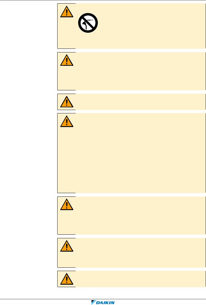
If you are NOT sure how to install or operate the unit, contact your dealer.
DANGER: RISK OF BURNING/SCALDING
▪Do NOT touch the refrigerant piping, water piping or internal parts during and immediately after operation. It could be too hot or too cold. Give it time to return to normal temperature. If you must touch it, wear protective gloves.
▪Do NOT touch any accidental leaking refrigerant.
WARNING
Improper installation or attachment of equipment or accessories could result in electrical shock, short-circuit, leaks, fire or other damage to the equipment. Only use accessories, optional equipment and spare parts made or approved by Daikin.
WARNING
Make sure installation, testing and applied materials comply with applicable legislation (on top of the instructions described in the Daikin documentation).
CAUTION
Wear adequate personal protective equipment (protective gloves, safety glasses,…) when installing, maintaining or servicing the system.
WARNING
Tear apart and throw away plastic packaging bags so that nobody, especially children, can play with them. Possible risk: suffocation.
WARNING
Provide adequate measures to prevent that the unit can be used as a shelter by small animals. Small animals that make contact with electrical parts can cause malfunctions, smoke or fire.
CAUTION
Do NOT touch the air inlet or aluminium fins of the unit.
RXYQQ8~20U7Y1B |
Installer and user reference guide |
VRV IV Q+ series heat pump |
9 |
4P546229-1A – 2020.10 |

2 | General safety precautions
CAUTION
▪ Do NOT place any objects or equipment on top of the unit.
▪ Do NOT sit, climb or stand on the unit.
NOTICE
Works executed on the outdoor unit are best done under dry weather conditions to avoid water ingress.
In accordance with the applicable legislation, it might be necessary to provide a logbook with the product containing at least: information on maintenance, repair work, results of tests, stand-by periods,…
Also, at least, following information MUST be provided at an accessible place at the product:
▪Instructions for shutting down the system in case of an emergency
▪Name and address of fire department, police and hospital
▪Name, address and day and night telephone numbers for obtaining service In Europe, EN378 provides the necessary guidance for this logbook.
2.1.2Installation site
▪Provide sufficient space around the unit for servicing and air circulation.
▪Make sure the installation site withstands the weight and vibration of the unit.
▪Make sure the area is well ventilated. Do NOT block any ventilation openings.
▪Make sure the unit is level.
Do NOT install the unit in the following places:
▪In potentially explosive atmospheres.
▪In places where there is machinery that emits electromagnetic waves. Electromagnetic waves may disturb the control system, and cause malfunction of the equipment.
▪In places where there is a risk of fire due to the leakage of flammable gases (example: thinner or gasoline), carbon fibre, ignitable dust.
▪In places where corrosive gas (example: sulphurous acid gas) is produced. Corrosion of copper pipes or soldered parts may cause the refrigerant to leak.
2.1.3Refrigerant — in case of R410A or R32
If applicable. See the installation manual or installer reference guide of your
application for more information.
NOTICE
Make sure refrigerant piping installation complies with applicable legislation. In
Europe, EN378 is the applicable standard.
NOTICE
Make sure the field piping and connections are NOT subjected to stress.
Installer and user reference guide |
RXYQQ8~20U7Y1B |
10 |
VRV IV Q+ series heat pump |
4P546229-1A – 2020.10 |
2 | General safety precautions
WARNING
During tests, NEVER pressurize the product with a pressure higher than the maximum allowable pressure (as indicated on the nameplate of the unit).
WARNING
Take sufficient precautions in case of refrigerant leakage. If refrigerant gas leaks, ventilate the area immediately. Possible risks:
▪Excessive refrigerant concentrations in a closed room can lead to oxygen deficiency.
▪Toxic gas might be produced if refrigerant gas comes into contact with fire.
DANGER: RISK OF EXPLOSION
Pump down – Refrigerant leakage. If you want to pump down the system, and there is a leak in the refrigerant circuit:
▪Do NOT use the unit's automatic pump down function, with which you can collect all refrigerant from the system into the outdoor unit. Possible consequence: Selfcombustion and explosion of the compressor because of air going into the operating compressor.
▪Use a separate recovery system so that the unit's compressor does NOT have to operate.
WARNING
ALWAYS recover the refrigerant. Do NOT release them directly into the environment.
Use a vacuum pump to evacuate the installation.
NOTICE
After all the piping has been connected, make sure there is no gas leak. Use nitrogen to perform a gas leak detection.
NOTICE
▪ To avoid compressor breakdown, do NOT charge more than the specified amount of refrigerant.
▪When the refrigerant system is to be opened, refrigerant MUST be treated according to the applicable legislation.
WARNING
Make sure there is no oxygen in the system. Refrigerant may only be charged after performing the leak test and the vacuum drying.
Possible consequence: Self-combustion and explosion of the compressor because of oxygen going into the operating compressor.
▪In case recharge is required, see the nameplate of the unit. It states the type of refrigerant and necessary amount.
▪The unit is factory charged with refrigerant and depending on pipe sizes and pipe lengths some systems require additional charging of refrigerant.
▪Only use tools exclusively for the refrigerant type used in the system, this to ensure pressure resistance and prevent foreign materials from entering into the system.
▪Charge the liquid refrigerant as follows:
RXYQQ8~20U7Y1B |
Installer and user reference guide |
VRV IV Q+ series heat pump |
11 |
4P546229-1A – 2020.10 |

2 | General safety precautions
If |
Then |
||
A siphon tube is present |
Charge with the cylinder upright. |
||
(i.e., the cylinder is marked with "Liquid |
|
|
|
filling siphon attached") |
|
|
|
|
|
||
A siphon tube is NOT present |
Charge with the cylinder upside down. |
||
|
|
|
|
|
|
|
|
▪Open refrigerant cylinders slowly.
▪Charge the refrigerant in liquid form. Adding it in gas form may prevent normal operation.
CAUTION
When the refrigerant charging procedure is done or when pausing, close the valve of the refrigerant tank immediately. If the valve is NOT closed immediately, remaining pressure might charge additional refrigerant. Possible consequence: Incorrect refrigerant amount.
2.1.4 Electrical
DANGER: RISK OF ELECTROCUTION
▪Turn OFF all power supply before removing the switch box cover, connecting electrical wiring or touching electrical parts.
▪Disconnect the power supply for more than 10 minutes, and measure the voltage at the terminals of main circuit capacitors or electrical components before servicing. The voltage MUST be less than 50 V DC before you can touch electrical components. For the location of the terminals, see the wiring diagram.
▪Do NOT touch electrical components with wet hands.
▪Do NOT leave the unit unattended when the service cover is removed.
WARNING
If NOT factory installed, a main switch or other means for disconnection, having a contact separation in all poles providing full disconnection under overvoltage category III condition, MUST be installed in the fixed wiring.
Installer and user reference guide |
RXYQQ8~20U7Y1B |
12 |
VRV IV Q+ series heat pump |
4P546229-1A – 2020.10 |
2 | General safety precautions
WARNING
▪ ONLY use copper wires.
▪Make sure the field wiring complies with the applicable legislation.
▪All field wiring MUST be performed in accordance with the wiring diagram supplied with the product.
▪NEVER squeeze bundled cables and make sure they do NOT come in contact with the piping and sharp edges. Make sure no external pressure is applied to the terminal connections.
▪Make sure to install earth wiring. Do NOT earth the unit to a utility pipe, surge absorber, or telephone earth. Incomplete earth may cause electrical shock.
▪Make sure to use a dedicated power circuit. NEVER use a power supply shared by another appliance.
▪Make sure to install the required fuses or circuit breakers.
▪Make sure to install an earth leakage protector. Failure to do so may cause electrical shock or fire.
▪When installing the earth leakage protector, make sure it is compatible with the inverter (resistant to high frequency electric noise) to avoid unnecessary opening of the earth leakage protector.
CAUTION
▪ When connecting the power supply: connect the earth cable first, before making the current-carrying connections.
▪When disconnecting the power supply: disconnect the current-carrying cables first, before separating the earth connection.
▪The length of the conductors between the power supply stress relief and the terminal block itself must be as such that the current-carrying wires are tautened before the earth wire is in case the power supply is pulled loose from the stress relief.
NOTICE
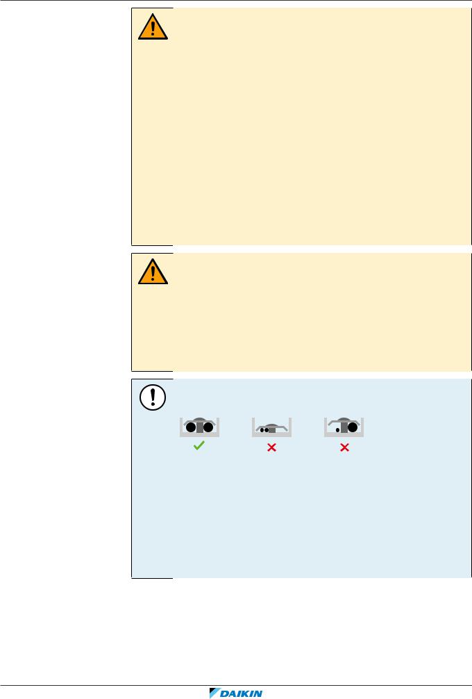
Precautions when laying power wiring:
▪Do NOT connect wiring of different thicknesses to the power terminal block (slack in the power wiring may cause abnormal heat).
▪When connecting wiring which is the same thickness, do as shown in the figure above.
▪For wiring, use the designated power wire and connect firmly, then secure to prevent outside pressure being exerted on the terminal board.
▪Use an appropriate screwdriver for tightening the terminal screws. A screwdriver with a small head will damage the head and make proper tightening impossible.
▪Over-tightening the terminal screws may break them.
Install power cables at least 1 m away from televisions or radios to prevent interference. Depending on the radio waves, a distance of 1 m may not be sufficient.
RXYQQ8~20U7Y1B |
Installer and user reference guide |
VRV IV Q+ series heat pump |
13 |
4P546229-1A – 2020.10 |

2 | General safety precautions
WARNING
▪ After finishing the electrical work, confirm that each electrical component and terminal inside the electrical components box is connected securely.
▪ Make sure all covers are closed before starting up the unit.
NOTICE
Only applicable if the power supply is three phase, and the compressor has an ON/
OFF starting method.
If there exists the possibility of reversed phase after a momentary black out and the power goes on and off while the product is operating, attach a reversed phase protection circuit locally. Running the product in reversed phase can break the compressor and other parts.
Installer and user reference guide |
RXYQQ8~20U7Y1B |
14 |
VRV IV Q+ series heat pump |
4P546229-1A – 2020.10 |
3 | Specific installer safety instructions
3 Specific installer safety instructions
Always observe the following safety instructions and regulations.
WARNING
Tear apart and throw away plastic packaging bags so that nobody, especially children, can play with them. Possible risk: suffocation.
CAUTION
Appliance not accessible to the general public, install it in a secured area, protected from easy access.
This unit, both indoor and outdoor, is suitable for installation in a commercial and light industrial environment.
CAUTION
Excessive refrigerant concentrations in a closed room can lead to oxygen deficiency.
DANGER: RISK OF ELECTROCUTION
Do NOT leave the unit unattended when the service cover is removed.
DANGER: RISK OF BURNING/SCALDING
DANGER: RISK OF ELECTROCUTION
WARNING
Take sufficient precautions in case of refrigerant leakage. If refrigerant gas leaks, ventilate the area immediately. Possible risks:
▪Excessive refrigerant concentrations in a closed room can lead to oxygen deficiency.
▪Toxic gas might be produced if refrigerant gas comes into contact with fire.
WARNING
ALWAYS recover the refrigerant. Do NOT release them directly into the environment.
Use a vacuum pump to evacuate the installation.
WARNING
During tests, NEVER pressurize the product with a pressure higher than the maximum allowable pressure (as indicated on the nameplate of the unit).
CAUTION
Do not vent gases into the atmosphere.
WARNING
Any gas or oil remaining inside the stop valve may blow off the spun piping.
If these instructions are NOT followed correctly it may result in property damage or personal injury, which may be serious depending on the circumstances.
RXYQQ8~20U7Y1B |
Installer and user reference guide |
VRV IV Q+ series heat pump |
15 |
4P546229-1A – 2020.10 |
3 | Specific installer safety instructions
WARNING
NEVER remove the spun piping by brazing.
Any gas or oil remaining inside the stop valve may blow off the spun piping.
WARNING
▪ ONLY use R410A as refrigerant. Other substances may cause explosions and accidents.
▪R410A contains fluorinated greenhouse gases. Its global warming potential (GWP) value is 2087.5. Do NOT vent these gases into the atmosphere.
▪When charging refrigerant, ALWAYS use protective gloves and safety glasses.
CAUTION
Do NOT push or place redundant cable length in the unit.
WARNING
▪ If the power supply has a missing or wrong N-phase, equipment might break down.
▪Establish proper earthing. Do NOT earth the unit to a utility pipe, surge absorber, or telephone earth. Incomplete earthing may cause electrical shock.
▪Install the required fuses or circuit breakers.
▪Secure the electrical wiring with cable ties so that the cables do NOT come in contact with sharp edges or piping, particularly on the high-pressure side.
▪Do NOT use taped wires, stranded conductor wires, extension cords, or connections from a star system. They can cause overheating, electrical shock or fire.
▪Do NOT install a phase advancing capacitor, because this unit is equipped with an inverter. A phase advancing capacitor will reduce performance and may cause accidents.
WARNING
▪ All wiring MUST be performed by an authorised electrician and MUST comply with the applicable legislation.
▪Make electrical connections to the fixed wiring.
▪All components procured on-site and all electrical construction MUST comply with the applicable legislation.
WARNING
For the existing power supply and transmission wiring, check that the specifications match the requirements described in this chapter and that other parts (especially terminals) do not appear to have deteriorated. Take the appropriate steps (e.g. replacement) if necessary.
WARNING
ALWAYS use multicore cable for power supply cables.
Installer and user reference guide |
RXYQQ8~20U7Y1B |
16 |
VRV IV Q+ series heat pump |
4P546229-1A – 2020.10 |
3 | Specific installer safety instructions
CAUTION
▪ When connecting the power supply: connect the earth cable first, before making the current-carrying connections.
▪When disconnecting the power supply: disconnect the current-carrying cables first, before separating the earth connection.
▪The length of the conductors between the power supply stress relief and the terminal block itself must be as such that the current-carrying wires are tautened before the earth wire is in case the power supply is pulled loose from the stress relief.
CAUTION
Do NOT perform the test operation while working on the indoor units.
When performing the test operation, NOT only the outdoor unit, but the connected indoor unit will operate as well. Working on an indoor unit while performing a test operation is dangerous.
CAUTION
Do NOT insert fingers, rods or other objects into the air inlet or outlet. Do NOT remove the fan guard. When the fan is rotating at high speed, it will cause injury.
RXYQQ8~20U7Y1B |
Installer and user reference guide |
VRV IV Q+ series heat pump |
17 |
4P546229-1A – 2020.10 |

For the user
| <![if ! IE]> <![endif]>For the user |
|
|
|
|
|
Installer and user reference guide |
RXYQQ8~20U7Y1B |
18 |
VRV IV Q+ series heat pump |
4P546229-1A – 2020.10 |

4 | User safety instructions
4 User safety instructions
Always observe the following safety instructions and regulations.
In this chapter
4.1 |
General.................................................................................................................................................................................... |
19 |
4.2 |
Instructions for safe operation............................................................................................................................................... |
20 |
4.1 General
WARNING
If you are NOT sure how to operate the unit, contact your installer.
WARNING
Children aged from 8 years and above and persons with reduced physical, sensory or mental capabilities or lack of experience and knowledge can only use this appliance if they have been given supervision or instruction concerning the use of the appliance by a person responsible for their safety.
Children MUST NOT play with the appliance.
Cleaning and user maintenance MUST NOT be carried out by children without supervision.
WARNING
To prevent electrical shocks or fire:
▪Do NOT rinse the unit.
▪Do NOT operate the unit with wet hands.
▪Do NOT place any objects containing water on the unit.
CAUTION
▪Do NOT place any objects or equipment on top of the unit.
▪Do NOT sit, climb or stand on the unit.
RXYQQ8~20U7Y1B |
Installer and user reference guide |
VRV IV Q+ series heat pump |
19 |
4P546229-1A – 2020.10 |

4 | User safety instructions
▪ Units are marked with the following symbol:
This means that electrical and electronic products may NOT be mixed with unsorted household waste. Do NOT try to dismantle the system yourself: the dismantling of the system, treatment of the refrigerant, of oil and of other parts must be done by an authorized installer and must comply with applicable legislation.
Units must be treated at a specialized treatment facility for reuse, recycling and recovery. By ensuring this product is disposed of correctly, you will help to prevent potential negative consequences for the environment and human health. For more information, contact your installer or local authority.
▪Batteries are marked with the following symbol:
This means that the batteries may NOT be mixed with unsorted household waste. If a chemical symbol is printed beneath the symbol, this chemical symbol means that the battery contains a heavy metal above a certain concentration.
Possible chemical symbols are: Pb: lead (>0.004%).
Waste batteries must be treated at a specialized treatment facility for reuse. By ensuring waste batteries are disposed of correctly, you will help to prevent potential negative consequences for the environment and human health.
4.2Instructions for safe operation
CAUTION
▪NEVER touch the internal parts of the controller.
▪Do NOT remove the front panel. Some parts inside are dangerous to touch and appliance problems may happen. For checking and adjusting the internal parts, contact your dealer.
CAUTION
Do NOT operate the system when using a room fumigation-type insecticide. Chemicals could collect in the unit, and endanger the health of people who are hypersensitive to chemicals.
CAUTION
It is unhealthy to expose your body to the air flow for a long time.
Installer and user reference guide |
RXYQQ8~20U7Y1B |
20 |
VRV IV Q+ series heat pump |
4P546229-1A – 2020.10 |
4 | User safety instructions
CAUTION
To avoid oxygen deficiency, ventilate the room sufficiently if equipment with burner is used together with the system.
WARNING
This unit contains electrical and hot parts.
WARNING
Before operating the unit, be sure the installation has been carried out correctly by an installer.
WARNING
Never touch the air outlet or the horizontal blades while the swing flap is in operation. Fingers may become caught or the unit may break down.
CAUTION
Do NOT insert fingers, rods or other objects into the air inlet or outlet. Do NOT remove the fan guard. When the fan is rotating at high speed, it will cause injury.
CAUTION: Pay attention to the fan!
It is dangerous to inspect the unit while the fan is running.
Be sure to turn off the main switch before executing any maintenance task.
CAUTION
After a long use, check the unit stand and fitting for damage. If damaged, the unit may fall and result in injury.
WARNING
NEVER replace a fuse with a fuse of a wrong ampere ratings or other wires when a fuse blows out. Use of wire or copper wire may cause the unit to break down or cause a fire.
RXYQQ8~20U7Y1B |
Installer and user reference guide |
VRV IV Q+ series heat pump |
21 |
4P546229-1A – 2020.10 |

4 | User safety instructions
WARNING
▪Do NOT modify, disassemble, remove, reinstall or repair the unit yourself as incorrect dismantling or installation may cause an electric shock or fire. Contact your dealer.
▪In case of accidental refrigerant leaks, make sure there are no naked flames. The refrigerant itself is entirely safe, non-toxic and non-combustible, but it will generate toxic gas when it accidentally leaks into a room where combustible air from fan heaters, gas cookers, etc. is present. Always have qualified service personnel confirm that the point of leakage has been repaired or corrected before resuming operation.
WARNING
Stop operation and shut off the power if anything unusual occurs (burning smells etc.).
Leaving the unit running under such circumstances may cause breakage, electric shock or fire. Contact your dealer.
WARNING
The refrigerant in the system is safe and normally does not leak. If the refrigerant leaks in the room, contact with a fire of a burner, a heater or a cooker may result in a harmful gas.
Turn off any combustible heating devices, ventilate the room and contact the dealer where you purchased the unit.
Do not use the system until a service person confirms that the portion where the refrigerant leaks is repaired.
CAUTION
NEVER expose little children, plants or animals directly to the airflow.
CAUTION
Do NOT touch the heat exchanger fins. These fins are sharp and could result in cutting injuries.
Installer and user reference guide |
RXYQQ8~20U7Y1B |
22 |
VRV IV Q+ series heat pump |
4P546229-1A – 2020.10 |

5 | About the system
5 About the system
The indoor unit part of VRV IV replacement heat pump system can be used for heating/cooling applications. The type of indoor unit which can be used depends on the outdoor units series.
NOTICE
Do NOT use the system for other purposes. In order to avoid any quality deterioration, do NOT use the unit for cooling precision instruments, food, plants, animals, or works of art.
NOTICE
For future modifications or expansions of your system:
A full overview of allowable combinations (for future system extensions) is available in technical engineering data and should be consulted. Contact your installer to receive more information and professional advice.
In general following type of indoor units can be connected to a VRV IV replacement heat pump system (not exhaustive list, depending on outdoor unit model and indoor unit model combinations):
▪VRV direct expansion (DX) indoor units for R410A (air to air applications).
▪AHU (air to air applications): EKEXV-kit+EKEQ-box are required, depending on the application.
▪VRV direct expansion (DX) indoor units for non-R410A (air to air applications). See "Possible combinations of indoor units" [457].
Airhandling unit connection in pair to VRV IV replacement heat pump outdoor unit is supported.
Airhandling unit connection in multi to VRV IV replacement heat pump outdoor unit is supported, even combined with VRV direct expansion indoor unit(s).
For more specifications, see technical engineering data.
In this chapter
5.1 |
System layout.......................................................................................................................................................................... |
23 |
5.1 System layout
e
a
|
|
|
|
|
|
|
|
|
|
|
|
|
|
|
|
|
|
|
|
|
|
|
|
|
|
|
|
|
|
|
|
|
|
|
|
|
|
|
|
|
|
|
|
|
|
|
|
|
|
|
|
|
|
|
|
|
|
|
|
|
|
|
|
|
|
|
|
|
|
|
|
|
|
|
|
|
|
|
|
|
|
|
|
|
|
|
|
|
|
|
|
|
|
|
|
|
|
|
|
|
|
|
|
|
|
|
c |
|
|
|
|
c |
|
|
|
|
b |
|
|
|
|
|
|
|
|||||||||||||
|
|
|
|
|
|
|||||||||||||||||
|
|
|
|
|
|
|
|
|
|
|
|
|
|
|
|
|
|
|
|
|
|
|
d d
d
aVRV IV replacement heat pump outdoor unit
bRefrigerant piping
cVRV direct expansion (DX) indoor unit
dUser interface (dedicated depending on indoor unit type)
eCool/Heat changeover remote control switch
RXYQQ8~20U7Y1B |
Installer and user reference guide |
VRV IV Q+ series heat pump |
23 |
4P546229-1A – 2020.10 |

6 | User interface
6 User interface
CAUTION
▪ NEVER touch the internal parts of the controller.
▪Do NOT remove the front panel. Some parts inside are dangerous to touch and appliance problems may happen. For checking and adjusting the internal parts, contact your dealer.
This operation manual offers a non-exhaustive overview of the main functions of the system.
Detailed information on required actions to achieve certain functions can be found in the dedicated installation and operation manual of the indoor unit.
Refer to the operation manual of the installed user interface.
Installer and user reference guide |
RXYQQ8~20U7Y1B |
24 |
VRV IV Q+ series heat pump |
4P546229-1A – 2020.10 |
7 | Before operation
7 Before operation
WARNING
Ask your dealer for improvement, repair, and maintenance. Incomplete improvement, repair, and maintenance may result in water leakage, electric shock and fire.
WARNING
Ask your dealer to move and reinstall the air conditioner. Incomplete installation may result in a water leakage, electric shock, and fire.
WARNING
NEVER let the indoor unit or the user interface get wet. It may cause an electric shock or a fire.
WARNING
Do NOT place objects in direct proximity of the outdoor unit and do NOT let leaves and other debris accumulate around the unit. Leaves are a hotbed for small animals which can enter the unit. Once in the unit, such animals can cause malfunctions, smoke or fire when making contact with electrical parts.
WARNING
Avoid placing the user interface in a place where it can be splashed with water. Water entering the machine may cause an electric leak or may damage the internal electronic parts.
WARNING
This unit contains electrical and hot parts.
WARNING
Before operating the unit, be sure the installation has been carried out correctly by an installer.
NOTICE
NEVER inspect or service the unit by yourself. Ask a qualified service person to perform this work.
CAUTION
Do NOT touch the heat exchanger fins. These fins are sharp and could result in cutting injuries.
WARNING
Do NOT place a flammable spray bottle near the air conditioner and do NOT use sprays near the unit. Doing so may result in a fire.
CAUTION
It is unhealthy to expose your body to the air flow for a long time.
RXYQQ8~20U7Y1B |
Installer and user reference guide |
VRV IV Q+ series heat pump |
25 |
4P546229-1A – 2020.10 |

7 | Before operation
CAUTION
To avoid oxygen deficiency, ventilate the room sufficiently if equipment with burner is used together with the system.
CAUTION
Do NOT operate the system when using a room fumigation-type insecticide. Chemicals could collect in the unit, and endanger the health of people who are hypersensitive to chemicals.
CAUTION
NEVER expose little children, plants or animals directly to the airflow.
NOTICE
NEVER press the button of the user interface with a hard, pointed object. The user interface may be damaged.
NOTICE
NEVER pull or twist the electric wire of the user interface. It may cause the unit to malfunction.
NOTICE
Do NOT place the user interface in a place exposed to direct sunlight. The LCD display may get discoloured or fail to display the data.
NOTICE
Do NOT place items which might be damaged by moisture under the indoor unit. Condensation may form if the humidity is above 80%, if the drain outlet is blocked or the filter is polluted.
NOTICE
Arrange the drain hose to ensure smooth drainage. Incomplete drainage may cause the building, furniture, etc. to get wet.
NOTICE
Be sure to turn ON the power 6 hours before operation in order to have power running to the crankcase heater and to protect the compressor.
This operation manual is for the following systems with standard control. Before initiating operation, contact your dealer for the operation that corresponds to your system type and mark. If your installation has a customised control system, ask your dealer for the operation that corresponds to your system.
Operation modes (depending on indoor unit type):
▪Heating and cooling (air to air).
▪Fan only operation (air to air).
Dedicated functions exist depending on the type of indoor unit, refer to dedicated installation/operation manual for more information.
Installer and user reference guide |
RXYQQ8~20U7Y1B |
26 |
VRV IV Q+ series heat pump |
4P546229-1A – 2020.10 |

8 | Operation
8 Operation
In this chapter
8.1 |
Operation range...................................................................................................................................................................... |
27 |
|
8.2 |
Operating the system ............................................................................................................................................................. |
27 |
|
|
8.2.1 |
About operating the system .................................................................................................................................. |
27 |
|
8.2.2 |
About cooling, heating, fan only, and automatic operation ................................................................................. |
28 |
|
8.2.3 |
About the heating operation ................................................................................................................................. |
28 |
|
8.2.4 |
To operate the system (WITHOUT cool/heat changeover remote control switch) ............................................. |
29 |
|
8.2.5 |
To operate the system (WITH cool/heat changeover remote control switch)..................................................... |
29 |
8.3 |
Using the dry program............................................................................................................................................................ |
30 |
|
|
8.3.1 |
About the dry program .......................................................................................................................................... |
30 |
|
8.3.2 |
To use the dry program (WITHOUT cool/heat changeover remote control switch)............................................ |
30 |
|
8.3.3 |
To use the dry program (WITH cool/heat changeover remote control switch) ................................................... |
30 |
8.4 |
Adjusting the air flow direction.............................................................................................................................................. |
31 |
|
|
8.4.1 |
About the air flow flap ........................................................................................................................................... |
31 |
8.5 |
Setting the master user interface .......................................................................................................................................... |
32 |
|
|
8.5.1 |
About setting the master user interface ............................................................................................................... |
32 |
|
8.5.2 |
To designate the master user interface (VRV DX and Hydrobox) ......................................................................... |
33 |
8.6 |
About control systems............................................................................................................................................................ |
33 |
|
8.1 Operation range
Use the system in the following temperature and humidity ranges for safe and
effective operation.
|
Cooling |
|
Heating |
Outdoor temperature |
–5~43°C DB |
|
–20~21°C DB |
|
|
|
–20~15.5°C WB |
|
|
|
|
Indoor temperature |
21~32°C DB |
|
15~27°C DB |
|
14~25°C WB |
|
|
|
|
|
|
Indoor humidity |
|
≤80%(a) |
|
|
|
|
|
(a)To avoid condensation and water dripping out of the unit. If the temperature or the humidity is beyond these conditions, safety devices may be put in action and the air conditioner may not operate.
Above operation range is only valid in case direct expansion indoor units are
connected to the VRV IV system.
8.2 Operating the system
8.2.1About operating the system
▪Operation procedure varies according to the combination of outdoor unit and user interface.
▪To protect the unit, turn on the main power switch 6 hours before operation.
▪If the main power supply is turned off during operation, operation will restart automatically after the power turns back on again.
RXYQQ8~20U7Y1B |
Installer and user reference guide |
VRV IV Q+ series heat pump |
27 |
4P546229-1A – 2020.10 |

8 | Operation
8.2.2About cooling, heating, fan only, and automatic operation
▪Changeover cannot be made with a user interface whose display shows  "change-over under centralised control" (refer to installation and operation manual of the user interface).
▪When the display  "change-over under centralised control" flashes, refer to "About setting the master user interface" [432].
▪The fan may keep on running for about 1 minute after the heating operation stops.
▪The air flow rate may adjust itself depending on the room temperature or the fan may stop immediately. This is not a malfunction.
8.2.3About the heating operation
It may take longer to reach the set temperature for general heating operation than for cooling operation.
The following operation is performed in order to prevent the heating capacity from dropping or cold air from blowing.
Defrost operation
In heating operation, freezing of the outdoor unit's air cooled coil increases over time, restricting the energy transfer to the outdoor unit's coil. Heating capability decreases and the system needs to go into defrost operation to be able to remove frost from the outdoor unit’s coil. During defrost operation the heating capacity on the indoor unit side will temporarily drop until defrosting is completed. After defrosting, the unit will regain its full heating capacity.
If |
Then |
RXYQQ outdoor unit is |
The indoor unit will stop fan operation, the |
installed |
refrigerant cycle will reverse and energy from inside |
|
the building will be used to defrost the outdoor unit |
|
coil. |
|
|
The indoor unit will indicate defrost operation on the display  .
.
Hot start
In order to prevent cold air from blowing out of an indoor unit at the start of heating operation, the indoor fan is automatically stopped. The display of the user interface shows  . It may take some time before the fan starts. This is not a malfunction.
INFORMATION
▪ The heating capacity drops when the outside temperature falls. If this happens, use another heating device together with the unit. (When using together with appliances that produce open fire, ventilate the room constantly). Do not place appliances that produce open fire in places exposed to the air flow from the unit or under the unit.
▪It takes some time to heat up the room from the time the unit is started since the unit uses a hot-air circulating system to heat the entire room.
▪If the hot air rises to the ceiling, leaving the area above the floor cold, we recommend that you use the circulator (the indoor fan for circulating air). Contact your dealer for details.
Installer and user reference guide |
RXYQQ8~20U7Y1B |
28 |
VRV IV Q+ series heat pump |
4P546229-1A – 2020.10 |
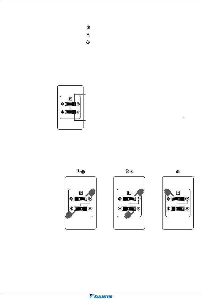
8 | Operation
8.2.4 To operate the system (WITHOUT cool/heat changeover remote control switch)
1Press the operation mode selector button on the user interface several times and select the operation mode of your choice.
Cooling operation
Heating operation
Fan only operation
2 Press the ON/OFF button on the user interface.
Result: The operation lamp lights up and the system starts operating.
8.2.5 To operate the system (WITH cool/heat changeover remote control switch)
Overview of the changeover remote control switch
a
b
aFAN ONLY/AIR CONDITIONING SELECTOR SWITCH
Set the switch to  for fan only operation or to
 for heating or cooling operation.
bCOOL/HEAT CHANGEOVER SWITCH
Set the switch to  for cooling or to

 for heating
Note: In case a cool/heat changeover remote control switch is used, the position of
DIP switch 1 (DS1-1) on the main PCB needs to be switched to the ON position.
To start
1 Select operation mode with the cool/heat changeover switch as follows:
Cooling operation |
Heating operation |
Fan only operation |
1 |
1 |
1 |
1 |
1 |
2Press the ON/OFF button on the user interface.
Result: The operation lamp lights up and the system starts operating.
To stop
3 Press the ON/OFF button on the user interface once again.
Result: The operation lamp goes out and the system stops operating.
RXYQQ8~20U7Y1B |
Installer and user reference guide |
VRV IV Q+ series heat pump |
29 |
4P546229-1A – 2020.10 |

8 | Operation
NOTICE
Do not turn off power immediately after the unit stops, but wait for at least 5
minutes.
To adjust
For programming temperature, fan speed and air flow direction refer to the
operation manual of the user interface.
8.3 Using the dry program
8.3.1About the dry program
▪The function of this program is to decrease the humidity in your room with minimal temperature decrease (minimal room cooling).
▪The micro computer automatically determines temperature and fan speed (cannot be set by the user interface).
▪The system does not go into operation if the room temperature is low (<20°C).
8.3.2To use the dry program (WITHOUT cool/heat changeover remote control switch)
To start
1Press the operation mode selector button on the user interface several times and select  (program dry operation).
2Press the ON/OFF button of the user interface.
Result: The operation lamp lights up and the system starts operating.
3Press the air flow direction adjust button (only for double-flow, multi-flow,
corner, ceiling-suspended and wall-mounted). Refer to "8.4 Adjusting the air flow direction" [431] for details.
To stop
4 Press the ON/OFF button on the user interface once again.
Result: The operation lamp goes out and the system stops operating.
NOTICE
Do not turn off power immediately after the unit stops, but wait for at least 5
minutes.
8.3.3 To use the dry program (WITH cool/heat changeover remote control switch)
To start
1Select cooling operation mode with the cool/heat changeover remote control switch.
Installer and user reference guide |
RXYQQ8~20U7Y1B |
30 |
VRV IV Q+ series heat pump |
4P546229-1A – 2020.10 |
Loading...