


 Loading...
Daikin RXYQ8PTLK, RXYQ10PTLK, RXYQ12PTLK, RXYQ16PTLK, RXYQ18PTLK Installation manuals
...INSTALLATION MANUAL


 System air conditioner
Installation manual |
|
VRVIII System air conditioner |
English |
|
|
|
|
|
|
RXYQ8PTLK(E) · PYNK(E)
RXYQ10PTLK(E) · PYNK(E)
RXYQ12PTLK(E) · PYNK(E)
RXYQ16PTLK(E) · PYNK(E)
RXYQ18PTLK(E) · PYNK(E)
RXYQ20PTLK(E) · PYNK(E)
RXYQ22PTLK(E) · PYNK(E)
RXYQ24PTLK(E) · PYNK(E)
RXYQ26PTLK(E) · PYNK(E)
RXYQ28PTLK(E) · PYNK(E)
RXYQ30PTLK(E) · PYNK(E)
RXYQ32PTLK(E) · PYNK(E)
RXYQ34PTLK(E) · PYNK(E)
RXYQ36PTLK(E) · PYNK(E)
[Q8 type] |
|
1 |
< If installed as a single unit > |
< When installed in serial > |
||||||||||
|
(Pattern 1) |
|
|
≥300 |
(Pattern 1) |
|
|
|
|
≥300 |
||||
|
|
|
|
|
|
|
|
|||||||
|
|
2 |
|
|
|
|
4 |
|
|
|
|
|
|
4 |
|
|
|
|
|
|
|
|
|
|
|
|
|
|
|
1, 2, 3 |
|
3 |
≥10 |
1 |
≥10 |
≥500 |
≥20 |
1 |
≥20 |
≥10 |
≥500 |
|||
|
|
|
|
≥10 |
|
|
||||||||
|
|
|
|
|
|
|
3 |
|
|
|
|
|
|
3 |
4 |
5 |
4 |
(Pattern 2) |
|
|
≥100 |
(Pattern 2) |
|
|
|
|
|
≥100 |
|
|
|
|
|
|
|
4 |
|
|
|
|
|
|
4 |
|
|
|
6 |
|
|
|
|
|
|
|
|
|
|
||
[Q10, 12 type] |
|
≥50 1 |
≥50 |
≥ |
500 |
≥50 |
1 |
≥ |
100 |
|
≥500 |
|||
|
|
≥100 |
|
|
||||||||||
|
|
7 |
|
|
|
|
|
|
|
≥50 |
||||
1, 2, 3 |
|
|
|
|
|
3 |
|
|
|
|
2 |
|
3 |
|
|
|
|
|
|
|
|
|
|
|
|
|
|
||
|
8 |
|
|
|
|
|
|
|
|
|
|
|
|
|
|
|
(Pattern 3) |
|
≥300 |
2 |
|
(Pattern 3) |
|
≥300 |
|
|
|||
|
|
|
|
|
|
|
|
|
|
|||||
|
|
9 |
|
|
|
|
|
|
|
|
|
|
|
|
4 |
|
11 |
≥200 |
|
1 |
|
|
≥200 |
≥400 |
1 |
|
≥400 |
|
|
|
10 |
|
|
|
|
|
|
|
|
|
|
|
|
|
figure 1 |
figure 2 |
|
figure 3 |
|
|
|
|
|
|
|
|
|
|
|
2
1500 |
<![if ! IE]> <![endif]>1000 |
≥ |
<![if ! IE]> <![endif]>≥ |
|
5
1
1000 ≥
3 ≥1000
4
≥1500 ≥1500 ≥1500
2 |
1 |
1 |
|
|
2
2
3 |
3 |
4 |
|
|
1 |
4 |
|
(mm)
figure 4
|
|
≥100 |
|
≥100 |
2 |
1 |
≥100 |
3 |
|
figure 5 |
|
|
|
|
figure 6 |
|
|
|
|
|
|
|
A |
|
1 |
|
|
|
|
|
|
B |
|
|
|
4 |
|
|
|
|
|
|
|
1 |
|
|
|
<![if ! IE]> <![endif]>) |
|
|
|
|
|
|
|
|
<![if ! IE]> <![endif]>3 |
|
|
|
|
|
5 |
|
2 |
<![if ! IE]> <![endif]>66( |
<![if ! IE]> <![endif]>66≥ |
<![if ! IE]> <![endif]>66≥ |
<![if ! IE]> <![endif]>737-722 |
<![if ! IE]> <![endif]>765 |
3 |
|
|
≥100 |
|
|
|
|
|
2 |
|
|
|
|
|
|
|
2 |
|
|
|
|
|
|
|
|
|
|
|
≥100 |
|
|
|
|
|
|
|
|
≥100 |
3 |
|
|
|
|
|
|
|
|
|
|
|
|
|
|
|
figure 7 |
|
|
|
|
|
figure 8 |
|
|
figure 9 |
|
|
|
|
6 |
|
1 |
2 |
1 |
2 |
1 |
2 |
|
|
|
|
|
4 |
5 |
|
|
3 |
|
|
|
|
|
|
|
6 |
|
|
|
|
|
|
|
|
|
|
|
4 |
|
5 |
3 |
|
3 |
3 |
|
|
|
|
|
|
|
|
||||
|
|
|
|
|
|
|
|
|
|
|
|
|
|
1 |
|
|
|
3 |
|
|
|
|
|
|
|
2 |
|
|
|
figure 10 |
|
|
|
figure 11 |
|
figure 12 |
|
figure 13 |
|
|
1 |
|
|
2 |
|
1 |
|
2 |
|
|
3 |
|
|
4 |
|
3 |
|
4 |
|
|
6 |
7 |
|
6 |
7 |
6 |
7 |
6 |
7 |
5 |
|
5 |
8 |
5 |
|
5 |
8 |
||
|
|
|
11 |
|
|
8 |
|||
|
|
|
|
|
|
12 |
|||
|
|
|
|
12 |
|
8 |
|||
|
|
8 |
|
|
|
||||
|
|
|
8 |
10 |
11 |
13 |
|||
10 |
|
|
13 |
|
|
14 |
14 |
|
9 |
|
9 |
|
|
|
|
|
15 |
|
16 |
|
|
figure 14 |
|
figure 15 |

|
|
|
|
|
|
|
|
|
|
|
|
18-1 |
|
|
|
|
|
|
|
|
|
|
|
|
C |
2 |
|
1 |
|
|
|
|
|
1 |
|
2 |
|
|
|
|
1 |
|
|
|
|
||
|
|
|
|
|
|
|
|
|
|
|
3 |
|
|
||
|
|
|
|
A |
|
|
|
|
|
|
|
|
|
|
|
|
|
A-arrow view |
3 |
4 |
|
|
|
|
|
|
|
|
|
||
|
|
|
|
|
|
|
|
4 |
|
|
|
||||
|
|
|
|
|
|
|
|
|
|
|
(C-arrow view) |
|
|
||
figure 16 |
|
|
|
|
|
|
|
|
|
|
|
|
|
|
|
|
|
|
|
|
|
|
|
|
D |
|
|
|
|
|
|
|
|
|
|
|
|
|
|
|
|
|
1 |
|
5 |
|
|
|
|
1 |
|
|
|
|
|
|
|
|
|
|
6 |
|
|
|
|
|
B |
|
|
|
|
1 |
|
4 |
|
|
|
|
|
|
|
|
|
|
|
|
|
|
|
|
|
|
|||
|
|
B-arrow view |
|
|
|
|
18-2 |
(D-arrow view) |
18-3 |
|
|||||
|
|
|
|
|
|
|
|
||||||||
figure 17 |
|
|
|
|
|
|
figure 18 |
|
|
|
|
|
|
|
|
|
|
|
|
|
|
|
|
1 |
|
|
|
|
|
|
|
|
|
|
|
|
|
|
|
2 |
|
|
|
|
12 |
|
12 |
|
|
|
|
|
|
|
|
|
|
|
|
|
|
||
|
|
|
|
|
|
|
|
9 |
|
|
|
|
8 |
|
13 |
1 |
|
|
5 |
|
|
|
|
|
|
|
11 |
|
|
|
|
|
|
|
|
|
|
10 |
|
|
|
|
|
|
|
||
|
2 |
|
|
3 |
|
|
|
|
|
|
|
|
|
|
|
|
4 |
|
|
4 |
|
|
|
|
|
|
|
|
|
|
|
1 |
3 |
|
|
|
|
|
|
|
|
|
|
|
|
|
|
|
2 |
|
6 |
7 |
|
|
|
8 |
3 |
|
|
|
|
|
|
|
|
|
8 |
|
|
|
|
|
|
|
|
|
|||
|
|
|
|
|
|
|
7 |
4 |
|
|
|
|
|
|
|
|
|
|
|
|
|
|
|
5 |
|
|
|
|
|
|
|
|
|
|
|
|
|
|
|
|
|
|
|
|
|
|
|
|
|
|
|
|
|
|
|
|
6 |
|
|
|
|
|
|
figure 19 |
|
|
|
|
|
figure 20 |
|
|
|
|
|
|
|
||
|
|
|
|
1 |
|
|
|
|
|
|
|
1 |
|
|
|
|
|
|
|
2 |
|
|
|
|
|
|
|
|
|
|
|
|
|
|
|
|
8 |
|
|
|
|
2 |
|
3 |
|
|
|
|
|
|
A5P |
A1P |
|
|
|
|
|
|
|
|
|||
|
|
|
|
|
|
|
A5P |
A1P |
|
A1P |
|
|
|||
|
|
|
|
TO IN/D UNIT TO OUT/D UNIT TO MULTI UNIT |
|
|
|
|
|
|
|
||||
|
|
3 |
A B C |
F1 F2 F1 F2 Q1 Q2 |
|
|
|
|
|
TO IN/D UNIT TO OUT/D UNIT TO MULTI UNIT |
TO MULTI UNIT |
|
|
||
|
|
|
|
|
|
|
|
A B C |
F1 F2 F1 F2 Q1 Q2 |
Q1 Q2 |
|
|
|||
|
|
|
|
|
|
|
|
|
|
|
|||||
|
|
A BC |
|
|
|
|
|
|
|
|
|
|
|
|
|
|
|
|
3 |
1 |
|
6 |
|
|
3 |
1 |
1 |
2 |
|
|
|
|
|
|
|
1 |
|
|
|
|
|
|
|
||||
|
|
|
|
|
|
|
|
|
|
|
|
|
|
|
|
|
|
|
|
4 |
|
|
|
|
|
|
|
|
|
|
|
|
|
|
5 |
F1 F2 |
F1 F2 |
F1 F2 |
|
|
4 |
|
6 |
|
|
|
|
|
|
|
|
|
|
|
5 |
|
|
|
|
||||
|
|
|
|
|
7 |
|
|
|
|
|
|
|
|
|
|
|
|
|
|
|
|
|
|
|
|
|
|
|
|
|
|
figure 21 |
|
|
|
|
|
|
figure 22 |
|
|
|
|
|
|
||
|
|
1 |
|
|
|
1 |
1 |
1 |
|
|
|
|
2 |
|
|
|
|
|
|
|
|
|
|
|
|
1 |
|
||||
|
|
|
|
|
|
|
|
7 |
|
|
|
|
|
|
|
|
|
|
|
|
|
|
|
|
|
|
|
|
(A1P) |
|
|
|
|
|
|
3 |
|
10 |
|
|
3 |
|
|
|
|
|
|
|
9 |
2 |
2 |
|
9 |
5 |
|
|
|
|
(A5P) |
|
|
||
|
|
|
2 |
2 |
|
|
|
|
|
|
|||||
|
|
|
|
4 |
|
|
|
|
|
|
|
(A5P) |
|
||
|
|
|
|
|
|
|
|
|
|
|
|
|
|
||
|
|
2 |
2 |
|
|
|
2 |
2 |
|
|
|
|
|
|
|
|
|
|
|
|
|
|
|
|
|
|
|
|
|
||
|
|
|
|
|
|
|
|
4 |
|
|
|
|
|
|
|
|
|
5 |
2 |
2 |
|
|
2 |
2 |
|
|
|
|
|
|
|
|
|
|
|
6 |
|
|
|
8 |
|
|
|
|
|
|
|
|
|
|
|
|
2 |
2 |
|
|
|
|
|
2 |
|
|
|
|
|
2 |
2 |
|
|
|
|
|
|
|
|
|
|||
|
|
|
|
|
|
|
|
|
|
|
|
|
|
||
|
|
|
|
|
|
2 |
2 |
6 |
|
|
|
|
|
|
|
|
|
|
|
|
|
|
|
|
|
|
|
|
|
||
figure 23 |
|
|
|
|
|
|
|
|
|
figure 24 |
|
|
|
||
|
|
|
|
|
|
|
|
|
|
|
|
5 |
L1 |
L2 |
L3 |
|
|
|
|
|
|
|
|
|
|
|
|
|
|||
|
|
|
|
|
|
1 |
|
|
|
|
|
|
|
|
|
|
|
|
|
|
|
|
|
|
|
|
|
|
|
|
6 |
|
|
|
|
|
|
3 |
|
|
|
|
|
|
|
|
|
|
|
|
|
|
|
|
|
4 |
|
|
|
|
|
|
|
|
|
|
|
2 |
|
|
|
|
|
|
|
|
|
|
|
|
|
|
|
|
|
2 |
|
|
|
|
|
|
|
|
|
|
|
|
|
3 |
|
|
|
|
|
|
|
|
|
|
7 |
|
|
|
|
|
|
|
|
|
|
|
|
|
|
4 |
|
|
|
|
|
|
|
|
|
|
|
|
|
|
|
|
|
|
1 |
|
|
|
|
|
|
|
|
|
|
|
|
|
|
|
|
|
|
4 |
|
|
|
|
|
|
|
|
|
|
8 |
|
5 |
|
|
|
|
|
|
|
|
|
|
|
|
|
|
|
|
|
|
|
|
|
|
|
|
|
|
|
|
|
|
figure 25 |
|
|
|
figure 26 |
|
|
|
|
|
|
|
|
|
||
|
|
[In case of 8HP type] |
|
1 |
|
[In case of 10, 12HP type] |
|
||||
|
|
|
|
|
|
||||||
|
|
|
|
|
11 |
13 |
|
|
|
|
11 |
|
1 |
|
10 |
|
|
|
|
|
10 |
|
|
|
|
2 |
12 |
|
9 |
|
|
|
|
12 |
9 |
|
|
|
|
|
2 |
|
|
|
|
||
|
|
|
|
|
|
|
|
|
|
|
|
|
|
3 |
|
|
8 |
3 |
|
|
|
|
8 |
|
|
|
|
|
|
|
|
|
|
||
|
|
|
|
|
|
|
|
|
|
|
|
|
|
|
|
|
|
15 |
|
|
|
|
|
|
|
4 |
|
6 |
|
4 |
|
|
|
6 |
|
|
|
5 |
|
7 |
|
5 |
7 |
||||
|
|
|
|
|
14 |
|
|||||
|
|
|
|
|
|
|
|
|
|
|
|
figure 27 |
|
|
|
|
|
|
|
|
|
|
|
|
|
|
7 |
14 |
|
1 |
6 |
|
1 |
|
3 |
|
|
|
|
|
|
|
|||||
|
|
|
8 |
13 |
13 |
|
|
|
|
|
|
|
|
6 |
|
|
|
|
|
|
|
||
|
|
9 |
|
|
|
|
|
|
|
4 |
|
1 |
|
|
10 |
|
|
2 |
5 |
|
|
|
|
2 |
3 |
|
|
|
|
|
|
|
|
||
|
11 |
|
15 |
|
|
|
|
|
|
||
|
|
|
|
|
|
|
|
|
|
||
|
|
5 |
12 |
|
3 |
|
|
|
|
|
|
|
4 |
: |
16 |
4 |
|
2 |
|
|
|||
|
|
|
|
: |
17 |
|
|
|
5 |
||
|
|
|
|
|
|
|
|
|
|||
|
|
|
|
|
|
|
|
|
|
|
|
figure 28 |
|
|
|
|
figure 29 |
|
figure 30 |
|
|
|
|
|
|
3 |
4 |
11 |
|
|
|
3 |
4 |
|
11 |
|
|
|
10 |
10 |
|
|
|
10 |
10 |
||
|
|
|
5 |
|
|
|
5 |
||||
|
|
|
6 |
|
|
|
|
|
6 |
|
|
|
|
1 |
7 |
|
|
|
1 |
|
7 |
|
|
|
|
8 |
|
12 |
|
|
8 |
|
|
||
|
|
2 |
|
|
|
|
|
12 |
|||
|
|
9 |
|
|
2 |
|
9 |
|
|||
|
|
13 |
|
|
|
|
13 |
||||
|
|
|
|
|
|
|
|
|
|
||
|
|
|
|
14 |
|
|
|
|
|
|
14 |
figure 31 |
|
|
|
|
figure 32 |
|
|
|
|
|
|
|
|
|
|
|
|
|
11 |
15 |
|
|
|
|
|
|
|
1 |
7 |
3 |
4 |
|
|
||
|
|
|
|
|
|
|
|
||||
|
|
3 |
5 |
|
|
|
|
|
|
||
|
|
1 |
7 |
|
5 |
10 |
10 |
|
10 |
||
|
|
4 |
|
|
|
||||||
|
|
5 |
|
|
|
6 |
|
||||
|
1 |
3 |
|
|
|
|
|
|
|
||
|
6 |
|
3 |
|
|
|
|
|
|||
|
1 |
4 |
6 |
|
|
7 |
|
|
|
|
|
|
2 |
|
3 |
1 |
8 |
|
|
|
9 |
||
|
|
|
|
|
|
|
|
||||
|
|
|
|
|
|
|
9 |
|
|
|
|
|
|
2 |
|
|
|
2 |
|
|
|
|
|
|
|
|
|
|
|
|
|
|
14 |
||
|
|
|
|
|
|
|
|
|
12 |
|
|
|
|
|
|
|
|
|
|
: |
|
|
|
|
|
|
|
|
|
|
|
: |
13 |
|
|
figure 33 |
|
|
|
|
figure 34 |
|
|
|
|
|
|
1
2
5 |
3 |
|
|
|
4 |
figure 35
RXYQ8PTLK(E) · PYNK(E) RXYQ10PTLK(E) · PYNK(E) RXYQ12PTLK(E) · PYNK(E) RXYQ16PTLK(E) · PYNK(E) RXYQ18PTLK(E) · PYNK(E)
RXYQ20PTLK(E) · PYNK(E) RXYQ22PTLK(E) · PYNK(E) RXYQ24PTLK(E) · PYNK(E) RXYQ26PTLK(E) · PYNK(E) RXYQ28PTLK(E) · PYNK(E)
RXYQ30PTLK(E) · PYNK(E) RXYQ32PTLK(E) · PYNK(E) RXYQ34PTLK(E) · PYNK(E) RXYQ36PTLK(E) · PYNK(E)
VRVIII System |
Installation |
air conditioner |
manual |
Meaning of WARNING and CAUTION notices
CONTENTS |
|
|
1. |
FIRST OF ALL ......................................................................... |
1 |
|
1-1. Safety precautions ............................................................ |
1 |
|
1-2. Special notice of product................................................... |
2 |
|
1-3. Disposal requirements ...................................................... |
2 |
2. |
INTRODUCTION...................................................................... |
2 |
|
2-1. Combination ...................................................................... |
2 |
|
2-2. Standard supplied accessories ......................................... |
3 |
|
2-3. Option accessory .............................................................. |
3 |
|
2-4. Technical and Electrical specifications ............................. |
3 |
|
2-5. Main components.............................................................. |
3 |
|
2-6. Installation Process........................................................... |
3 |
3. |
SELECTION OF LOCATION ................................................... |
3 |
4. |
INSPECTING AND HANDLING THE UNIT ............................. |
4 |
5. |
PLACING THE UNIT................................................................ |
4 |
6. |
REFRIGERANT PIPING .......................................................... |
4 |
|
6-1. Selection of piping material and Refrigerant |
|
|
branching kit...................................................................... |
4 |
|
6-2. Protection against contamination when installing pipes.... |
5 |
|
6-3. Pipe connection ................................................................ |
5 |
|
6-4. Connecting the refrigerant piping...................................... |
5 |
|
6-5. Example of connection...................................................... |
8 |
7. |
FIELD WIRING ...................................................................... |
10 |
|
7-1. Power circuit, safety device, and cable requirements ..... |
10 |
|
7-2. Wiring Connection Example for Whole System .............. |
10 |
|
7-3. Leading wire Procedure .................................................. |
11 |
|
7-4. Transmission Wiring Connection Procedure................... |
11 |
|
7-5. Power Wiring Connection Procedure .............................. |
11 |
|
7-6. Procedure for Wiring Inside Units ................................... |
12 |
8. |
AIR TIGHT TEST AND VACUUM DRYING ........................... |
12 |
|
8-1. Preparations.................................................................... |
12 |
|
8-2. Air tight test and vacuum drying method......................... |
13 |
9. |
PIPE INSULATION ................................................................ |
13 |
10. |
CHECKING OF DEVICE AND INSTALLATION |
|
|
CONDITIONS ........................................................................ |
13 |
11. |
ADDITIONAL REFRIGERANT CHARGE AND |
|
|
CHECK OPERATION ............................................................ |
13 |
|
11-1. Before working .............................................................. |
13 |
|
11-2. Procedure of Adding Refrigerant charging and |
|
|
check operation............................................................. |
15 |
12. |
ONSITE SETTINGS............................................................... |
18 |
|
12-1. Onsite Settings With the Power Off .............................. |
18 |
|
12-2. Onsite Settings With the Power On .............................. |
18 |
13. |
TEST RUN ............................................................................. |
18 |
|
13-1. Before test run .............................................................. |
18 |
|
13-2. Test Run ....................................................................... |
18 |
|
13-3. Checks After Test Run.................................................. |
18 |
14. |
CAUTION FOR REFRIGERANT LEAKS ............................... |
18 |
1.FIRST OF ALL
•This document is an installation manual for the Daikin RXYQ-P Series VRV Inverter. Before installing the unit, read this manual thoroughly, and following the instructions contained in it. After installation, do a test run to make sure the unit runs properly, and then explain how to operate and take care of the unit to the customer, using the operation manual.
•Lastly, make sure the customer keeps this manual, along with the operation manual, in a safe place.
•This manual does not describe how to install the indoor unit.
Refer to the installation manual included with the indoor unit for that.
1-1 Safety precautions
Please read these “Safety precautions” carefully before installing air conditioning unit and be sure to install it correctly.
After completing installation, conduct a trial operation to check for faults and explain to the customer how to operate the air conditioner and take care of it with the aid of the operation manual.
Ask the customer to store the installation manual along with the operation manual for future reference.
Warning ........Failure to follow these instructions properly may result in personal injury or loss of life.
Caution .........Failure to observe these instructions properly may result in property damage or personal injury, which may be serious depending on the circumstances.

 Warning
•Ask your dealer or qualified personnel to carry out installation work.
Do not attempt to install the air conditioner yourself. Improper installation may result in water leakage, electric shocks or fire.
•Install the air conditioner in accordance with the instructions in this installation manual.
Improper installation may result in water leakage, electric shocks or fire.
•When installing the unit in a small room, take measures against to keep refrigerant concentration from exceeding allowable safety limits in the event of refrigerant leakage.
Contact the place of purchase for more information. Excessive refrigerant in a closed ambient can lead to oxygen deficiency.
•Be sure to use only the specified accessories and parts for installation work.
Failure to use the specified parts may result in the unit falling, water leakage, electric shocks or fire.
•Install the air conditioner on a foundation strong enough to withstand the weight of the unit.
A foundation of insufficient strength may result in the equipment falling and causing injury.
•Carry out the specified installation work after taking into account strong winds, typhoons or earthquakes.
Failure to do so during installation work may result in the unit falling and causing accidents.
•Make sure that a separate power supply circuit is provided for this unit and that all electrical work is carried out by qualified personnel according to local laws and regulations and this installation manual.
An insufficient power supply capacity or improper electrical construction may lead to electric shocks or fire.
•Make sure that all wiring is secured, the specified wires are used, and that there is no strain on the terminal connections or wires. Improper connections or securing of wires may result in abnormal heat build-up or fire.
•When wiring the power supply and connecting the remote controller wiring and transmission wiring, position the wires so that the EL.COMPO.BOX lid can be securely fastened.
Improper positioning of the EL.COMPO.BOX lid may result in electric shocks, fire or the terminals overheating.
•If refrigerant gas leaks during installation, ventilate the area immediately.
Toxic gas may be produced if the refrigerant comes into contact with fire.
•After completing installation, check for refrigerant gas leakage. Toxic gas may be produced if the refrigerant gas leaks into the room and comes into contact with a source of fire, such as a fan heater, stove or cooker.
•Do not directly touch refrigerant that has leaked from refrigerant pipes or other areas, as there is a danger of frostbite.
•Be sure to switch off the unit before touching any electrical parts.
•Do not allow children to climb on the outdoor unit and avoid placing objects on the unit.
Injury may result if the unit becomes loose and falls.
•Be sure to earth the air conditioner.
Do not earth the unit to a utility pipe, lightning conductor or telephone earth lead.
Imperfect earthing may result in electric shocks or fire.
A high surge current from lightning or other sources may cause damage to the air conditioner.
•Be sure to install an earth leakage breaker.
Failure to install an earth leakage breaker may result in electric shocks or fire.


 Caution
•While following the instructions in this installation manual, install drain piping to ensure proper drainage and insulate piping to prevent condensation.
Improper drain piping may result in indoor water leakage and property damage.
English |
1 |
•Install the indoor and outdoor units, power cord and connecting wires at least 1 meter away from televisions or radios to prevent picture interference and noise.
(Depending on the incoming signal strength, a distance of 1 meter may not be sufficient to eliminate noise.)
•Remote controller (wireless kit) transmitting distance can be shorter than expected in rooms with electronic fluorescent lamps (inverter or rapid start types).
Install the indoor unit as far away from fluorescent lamps as possible.
•Make sure to provide for adequate measures in order to prevent that the outdoor unit be used as a shelter by small animals. Small animals making contact with electrical parts can cause malfunctions, smoke or fire. Please instruct the customer to keep the area around the unit clean.
•Do not install the air conditioner in the following locations:
1.Where there is a high concentration of mineral oil spray or vapour (e.g. a kitchen).
Plastic parts will deteriorate, parts may fall off and water leakage could result.
2.Where corrosive gas, such as sulphurous acid gas, is produced.
Corroding of copper pipes or soldered parts may result in refrigerant leakage.
3.Near machinery emitting electromagnetic radiation. Electromagnetic radiation may disturb the operation of the control system and result in a malfunction of the unit.
4.Where flammable gas may leak, where there is carbon fibre or ignitable dust suspensions in the air, or where volatile flammables such as paint thinner or gasoline are handled.
Operating the unit in such conditions may result in fire.
1-2 Special notice of product
[CLASSIFICATION]
This air conditioner comes under the term “appliances not accessible to the general public”.
[REFRIGERANT]
VRVIII System use R410A refrigerant.
• The refrigerant R410A requires that strict precautions be observed for keeping the system clean, dry and tightly sealed. Read the chapter “REFRIGERANT PIPING” carefully and follow these procedures correctly.
A.Clean and dry
Strict measures must be taken to keep impurities (including SUNISO oil and other mineral oils as well as moisture) out of the system.
B.Tight sealed
Take care to keep the system tight when installing.
R410A contains no chlorine, does not destroy the ozone layer and so does not reduce the earth’s protection against harmful ultraviolet radiation.
R410A will contribute only slightly to the greenhouse effect if released into the atmosphere.
•Since R410A is a mixed refrigerant, the required additional refrigerant must be charged in its liquid state. (If the system is charged with refrigerant in its gaseous state, due to composition change,
the system will not function normally.)
[DESIGN PRESSURE]
Since design pressure is 4.0MPa or 40bar (for R407C units: 3.3MPa or 33bar),the wall thickness of pipes should be more carefully selected in accordance with the relevant local and national regulations.
1-3 Disposal requirements
Dismantling of the unit, treatment of the refrigerant, of oil and of other parts must be done in accordance with relevant local and national legislation.
2.INTRODUCTION
•RXYQ-P series are designed for outdoor installation and used for cooling and heatpump applications. Outdoor units come in three standard sizes, and with a single system through a multi system combining up to three outdoor units, rated cooling capacity from
17.7kW to 81.6 kW and rated heating capacity from 25.0 kW to
112.5kW can be achieved.
•The RXYQ-P units can be combined with Daikin VRV series indoor units for air conditioning purposes. Always use appropriate indoor units compatible with R410A. To lean which models of indoor units are compatible with R410A, refer to the product catalogs.
To combine with other refrigerant indoor unit will cause malfunction.
2-1 Combination
The indoor units can be installed in the following range.
Outdoor unit |
Total capacity of indoor units |
Total quantity of indoor units |
||
RXYQ8PTLK(E) · PYNK(E) |
........... |
100 |
~260 |
13 units |
RXYQ10PTLK(E) · PYNK(E).......... |
125 |
~325 |
16 units |
|
RXYQ12PTLK(E) · PYNK(E).......... |
150 |
~390 |
19 units |
|
RXYQ16PTLK(E) · PYNK(E).......... |
200 |
~520 |
26 units |
|
RXYQ18PTLK(E) · PYNK(E).......... |
225 |
~585 |
29 units |
|
RXYQ20PTLK(E) · PYNK(E).......... |
250 |
~650 |
32 units |
|
RXYQ22PTLK(E) · PYNK(E).......... |
275 |
~715 |
35 units |
|
RXYQ24PTLK(E) · PYNK(E).......... |
300 |
~780 |
39 units |
|
RXYQ26PTLK(E) · PYNK(E).......... |
325 |
~845 |
42 units |
|
RXYQ28PTLK(E) · PYNK(E).......... |
350 |
~910 |
45 units |
|
RXYQ30PTLK(E) · PYNK(E).......... |
375 |
~975 |
48 units |
|
RXYQ32PTLK(E) · PYNK(E).......... |
400 |
~1040 |
52 units |
|
RXYQ34PTLK(E) · PYNK(E).......... |
425 |
~1105 |
55 units |
|
RXYQ36PTLK(E) · PYNK(E).......... |
450 |
~1170 |
58 units |
|
Note 

•Be sure to connect an R410A indoor unit.
See the catalog for indoor unit models which can be connected.
•At above is the total capacity and total number of units of the indoor units when configured in a standard combination. See the technical reference for details on total capacity and total number of indoor units when using a configuration other than the standard combination. The standard combination are as follows.
<Combination unit> |
<Independent unit> |
RXYQ8PTLK(E) · PYNK(E) |
RXYQ8PTLK(E) · PYNK(E) |
RXYQ10PTLK(E) · PYNK(E) |
RXYQ10PTLK(E) · PYNK(E) |
RXYQ12PTLK(E) · PYNK(E) |
RXYQ12PTLK(E) · PYNK(E) |
RXYQ16PTLK(E) · PYNK(E) |
RXYQ8PTLK(E) · PYNK(E)+ RXYQ8PTLK(E) · PYNK(E) |
RXYQ18PTLK(E) · PYNK(E) |
RXYQ8PTLK(E) · PYNK(E)+ RXYQ10PTLK(E) · PYNK(E) |
RXYQ20PTLK(E) · PYNK(E) |
RXYQ8PTLK(E) · PYNK(E)+ RXYQ12PTLK(E) · PYNK(E) |
RXYQ22PTLK(E) · PYNK(E) |
RXYQ10PTLK(E) · PYNK(E)+ RXYQ12PTLK(E) · PYNK(E) |
RXYQ24PTLK(E) · PYNK(E) |
RXYQ12PTLK(E) · PYNK(E)+ RXYQ12PTLK(E) · PYNK(E) |
RXYQ26PTLK(E) · PYNK(E) |
RXYQ8PTLK(E) · PYNK(E)+ RXYQ8PTLK(E) · PYNK(E)+ RXYQ10PTLK(E) · PYNK(E) |
RXYQ28PTLK(E) · PYNK(E) |
RXYQ8PTLK(E) · PYNK(E)+ RXYQ10PTLK(E) · PYNK(E)+ RXYQ10PTLK(E) · PYNK(E) |
RXYQ30PTLK(E) · PYNK(E) |
RXYQ8PTLK(E) · PYNK(E)+ RXYQ10PTLK(E) · PYNK(E)+ RXYQ12PTLK(E) · PYNK(E) |
RXYQ32PTLK(E) · PYNK(E) |
RXYQ10PTLK(E) · PYNK(E)+ RXYQ10PTLK(E) · PYNK(E)+ RXYQ12PTLK(E) · PYNK(E) |
RXYQ34PTLK(E) · PYNK(E) |
RXYQ10PTLK(E) · PYNK(E)+ RXYQ12PTLK(E) · PYNK(E)+ RXYQ12PTLK(E) · PYNK(E) |
RXYQ36PTLK(E) · PYNK(E) |
RXYQ12PTLK(E) · PYNK(E)+ RXYQ12PTLK(E) · PYNK(E)+ RXYQ12PTLK(E) · PYNK(E) |
•If the total capacity of the connected indoor units exceeds the capacity of the outdoor unit, cooling and heating performance may drop when running the indoor units. See the capacity table in the Engineering Data Book for details.
•There are restrictions on the refrigerant pipe connecting order between outdoor unit in the case of the multi system.
Install so that the following restrictions are satisfied. <Restrictions>
The capacities of outdoor units A, B and C must fulfill the following
conditions.
A ≥ B ≥ C
Outdoor |
Outdoor |
Outdoor |
unit A |
unit B |
unit C |
to indoor unit |
|
|
Outdoor unit |
Outdoor unit multi |
|
multi connection |
||
piping kit |
connection piping kit |
|
(first branch) |
(second branch) |
|
2 |
English |
2-2 Standard supplied accessories
The following accessories are included. The storage location of the accessories is shown in figure 1.
Q8~Q12 type
|
|
|
|
Gas side |
Name |
Clamp (1) |
Clamp (2) |
Clamp (3) |
accessory |
|
|
|
|
pipe (1) |
Quantity |
9 pcs. |
2 pcs. |
1 pc. |
1 pc. |
Shape
Small
Large
Q8~Q12 type
|
Gas side |
Liquid side |
Liquid side |
|
||
Name |
accessory |
accessory |
accessory |
Others |
||
|
pipe (2) |
pipe (1) |
pipe (2) |
|
||
Quantity |
1 pc. |
|
1 pc. |
1 pc. |
• Operation |
|
|
|
|
|
|
|
manual |
|
|
|
|
|
|
• Installation |
|
|
|
|
|
|
manual |
|
|
|
|
|
|
• “REQUEST |
Shape |
|
|
|
|
|
FOR THE |
|
8, 10 |
12 |
|
8, 10 |
12 |
INDICA- |
|
|
TION” label |
||||
|
HP type HP type |
|
HP type |
HP type |
(Installation |
|
|
|
|
|
|
|
records) |
(Refer to figure 1)
1.Operation manual
2.Installation manual
3.Clamps
4.Accessory pipes
Note 

Do not throw away any of the accessories until installation is complete.
2-3 Option accessory
To install the outdoor units, the following optional parts are also required. To select an optimum kit, refer to “6. REFRIGERANT PIPING”.
• Refrigerant branching kit
REFNET header |
KHRP26M22H |
KHRP26M33H |
KHRP26M72H |
KHRP26M73H |
|||
REFNET joint |
KHRP26A22T |
KHRP26A33T |
KHRP26A72T |
KHRP26A73T |
|||
• Outdoor unit multi connection piping kit |
|
||||||
|
|
|
|
|
|
||
Number of outdoor units connected |
|
2 units |
3 units |
||||
Kit name |
|
|
|
|
|
BHFP22P100 |
BHFP22P151 |
• Pipe size reducer |
|
|
|
|
|
||
|
|
|
|
|
|||
Kit name |
|
KHRP26M73TP |
KHRP26M73HP |
|
|||
Note 

Make sure that any separately purchased accessories are designed for use with R410A.
2-4 Technical and Electrical specifications
Refer to the Engineering Data Book for the complete list of specifications.
2-5 Main components
For main components and function of the main components, refer to the Engineering Data Book.
2-6 Installation Process
Figure 2 shows the installation process. Install in the order of the steps shown.
(Refer to figure 2)
1.“3. SELECTION OF LOCATION”
2.“4. INSPECTING AND HANDLING THE UNIT”
3.“5. PLACING THE UNIT”
4.“6. REFRIGERANT PIPING”
5.“7. FIELD WIRING”
6.“8. AIR TIGHT TEST AND VACUUM DRYING”
7.“9. PIPE INSULATION”
8.“10. CHECKING OF DEVICE AND INSTALLATION CONDITIONS”
9.“11. ADDITIONAL REFRIGERANT CHARGE AND CHECK OPERATION”
10.“13. TEST RUN”
11.Operations which require the power to be turned on.
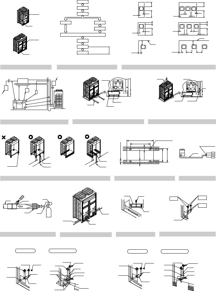
3.SELECTION OF LOCATION
Select a location for installation that meets the following conditions. Get the customer’s permission.
1.There is no danger of fire due to leakage of inflammable gas.
2.Select the location of the unit in such a way that neither the discharged air nor the sound generated by the unit disturb anyone.
3.The foundation is strong enough to support the weight of the unit and the floor is flat to prevent vibration and noise generation.
4.The piping length between the outdoor unit and the indoor unit may not exceed the allowable piping length. (Refer to
“6. REFRIGERANT PIPING”)
5.Locations where the unit’s suction vent and outlet vent do not generally face the wind.
Wind blowing directly into the suction or outlet vents will interfere with the unit’s operation.
If necessary, install some kind of obstruction to block the wind.
6.The space around the unit is adequate for servicing and the minimum space for air inlet and air outlet is available.
(See the “Installation Space Examples” for the minimum space requirements.)
Installation Space Examples
•The installation space requirement shown in figure 3 is a reference for cooling operation when the outdoor temperature is 35°C. If the design outdoor temperature exceeds 35°C or the heat load exceeds maximum capacity in all the outdoor unit, take an even large space on the intake shown in figure 3.
•During installation, install the units using the most appropriate of the patterns shown in figure 3 for the location in question, taking into consideration human traffic and wind.
•If the number of units installed is more than that shown in the pattern in figure 3, install the units so there are no short circuits.
•As regards space in front of the unit, consider the space needed for the local refrigerant piping when installing the units.
•If the work conditions in figure 3 do not apply, contact your dealer or Daikin directly.
(Refer to figure 3)
1.Front side
2.No limit to wall height
3.Service space of front side
4.Service space of suction side
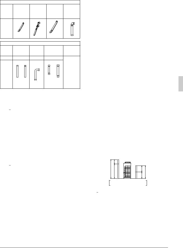
For Patterns 1 and 2 in figure 3:
•Wall height for front side no higher than 1500 mm.
•Wall height on the suction side no higher than 500 mm.
•Wall height for sides – no limit.
•If the height is exceeded the above, calculate h1 and h2 shown in the figure below, and add h1/2 to the service space of front side and h2/2 to the service space of suction side.
| <![if ! IE]> <![endif]>A |
<![if ! IE]> <![endif]>1500 h1 |
<![if ! IE]> <![endif]>Front side |
<![if ! IE]> <![endif]>Suction side |
<![if ! IE]> <![endif]>500 h2 |
<![if ! IE]> <![endif]>B |
h1 = A (Actual height) – 1500
h2 = B (Actual height) – 500
Note 

1.An inverter air conditioner may cause electronic noise generated from AM broadcasting. Examine where to install the main air conditioner and electric wires, keeping proper distances away from stereo equipment, personal computers, etc. Particularly for locations with weak reception, ensure there is a distance of at least 3 meters for indoor remote controllers, place power wiring and transmission wiring in conduits, and ground the conduits.
(Refer to figure 4)
1.Indoor unit
2.Branch switch, overcurrent breaker
3.Remote controller
4.COOL/HEAT selector
5.Personal computer or radio
English |
3 |
2.When installing in a locations where there is heavy snowfall, implement the following snow measures.
•Ensure the base is high enough that intakes are not clogged by snow.
•Remove the rear intake grille to prevent snow from accumulating on the fins.
3.If condensate may drip on downstairs (or walkway) depending on the floor condition, take a measure such as the installation of central drain pan kit (sold separately).
4.The refrigerant R410A itself is nontoxic, nonflammable and is safe. If the refrigerant should leak however, its concentration may exceed the allowable limit depending on room size. Due to this it could be necessary to take measures against leakage. See “14. CAUTION FOR REFRIGERANT LEAKS” for details.
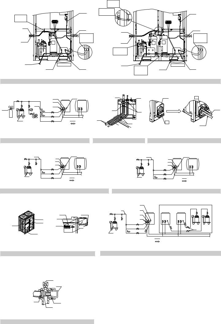
4.INSPECTING AND HANDLING THE UNIT
•At delivery, the package should be checked and any damage should be reported immediately to the carrier claims agent.
•When handling the unit, take into account the following:
1. 

 Fragile, handle the unit with care.
Keep the unit upright in order to avoid compressor damage.
2.Decide on the transportation route.
3.If a forklift is to be used, pass the forklift arms through the large openings on the bottom of the unit. (Refer to figure 5)
4.If hanging the unit, use a cloth sling to prevent damaging the unit. Keeping the following points in mind, hang the unit following the procedure shown in figure 6.
•Use a sling sufficiently strong to hold the mass of the unit.
•Use 2 belts of at least 8m long.
•Place extra cloth or boards in the locations where the casing comes in contact with the sling to prevent damage.
•Hoist the unit making sure it is being lifted at its center of gravity.
5.After installation, remove the transportation clasp attached to the large openings. (Refer to figure 6)
(Refer to figure 5)
1.Fork
2.Hole (large)
3.Transportation clasp (yellow)
4.Fixed screws of transportation clasp
(Refer to figure 6)
1.Belt sling
2.Board
3.Hole (large)
4.Hole (small)
Note 

Apply a filler cloth on a fork to prevent coating of the bottom frame from coming off and rust from occurring when bringing in the unit with anti-corrosion treatment type using a forklift.
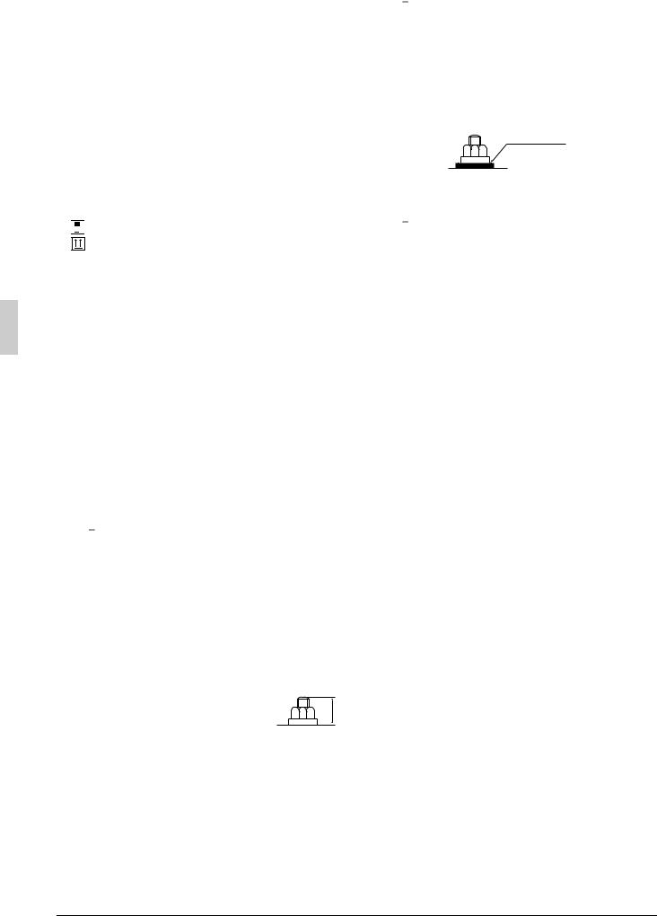
5.PLACING THE UNIT
•Make sure the unit is installed level on a sufficiently strong base to prevent vibration and noise. (Refer to figure 7)
•The base should be bigger around than the width of the unit’s legs (66 mm), and should support the unit. (Refer to figure 8)
If protective rubber is to be attached, attach it to the whole face of the base.
•The height of the base should be at least 150mm from the floor.
•Secure the unit to its base using foundation bolts. (Use four commercially available M12-type foundation bolts, nuts, and washers.)
•The foundation bolts should be inserted 20 mm.
(Refer to figure 7) |
<![if ! IE]> <![endif]>20 |
||
1. |
The product cannot be supported |
||
|
|||
2. |
only with four corners. |
|
|
Make sure to use the center sup- |
|
||
3. |
ports. |
|
|
Center of the product |
|
||
(Refer to figure 8)
1.Foundation bolt point (φ15 dia. : 4 positions)
2.Depth of product
3.Width of support leg
Model |
A |
B |
8HP type |
930 |
792 |
10 · 12HP type |
1240 |
1102 |
Note 

•There are restrictions on the refrigerant pipe connecting order between outdoor unit in the case of the multi system.
See the Note in “2-1 Combination” for detail.
•When installing on a roof, make sure the roof floor is strong enough and be sure to water-proof all work.
•Make sure the area around the machine drains properly by setting up drainage grooves around the foundation.
Drain water is sometimes discharged from the outdoor unit when it is running.
•For anti-corrosion type use nuts with resin washers. If the paint on nut connections comes off, the anti-corrosion effect may decrease.
Resin washers
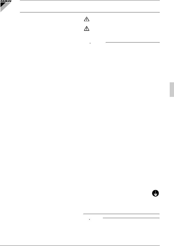
6.REFRIGERANT PIPING
Note 

•All field piping must be installed by a licensed refrigeration technician and must comply with relevant local and national regulations.
•After piping work is complete, do not under any circumstances open the shutoff valve until “7. FIELD WIRING” and “10. CHECKING OF DEVICE AND INSTALLATION CONDITIONS” are complete.
•Do not use flux when brazing the refrigerant piping. Use the phosphor copper brazing filler metal (BCuP-2: JIS Z 3264/B-Cu93P- 710/795: ISO 3677) which does not require flux.
(Flux has extremely harmful influence on refrigerant piping systems. For instance, if the chlorine based flux is used, it will cause pipe corrosion or, in particular, if the flux contains fluorine, it will damage the refrigerant oil.)
6-1 Selection of piping material and Refrigerant branching kit
•Use only pipes which are clean inside and outside and which do not accumulate harmful sulfur, oxidants, dirt, cutting oils, moisture, or other contamination. (Foreign materials inside pipes including oils for fabrication must be 30mg/10m or less.)
•Use the following items for the refrigerant piping.
Material: Jointless phosphor-deoxidized copper pipe
Size: See “6-5 Example of connection” to determine the correct size.
Thickness: Select a thickness for the refrigerant piping which complies with national and local laws.
For R410A, the design pressure is 4.0 MPa (40-bar).
The minimum thickness of piping according to Japan’s HighPressure Gas Safety Law (as of January 2003) is shown below.
Temper grade (O type, 1/2H type) in the table indicate the material types specified in JIS H 3300.
(unit: mm)
Temper grade |
|
O type |
|
|
|
|
|
|
|
||
|
|
|
|
|
|
|
|
|
|
|
|
outer diameter |
φ6.4 |
φ9.5 |
|
φ12.7 |
|
φ15.9 |
|
|
|
|
|
|
|
|
|
|
|
|
|
|
|
|
|
smallest thickness |
0.80 |
0.80 |
0.80 |
0.99 |
|
|
|
|
|
||
|
|
|
|
|
|
|
|
|
|
(unit: mm) |
|
|
|
|
|
|
|
|
|||||
Temper grade |
|
|
|
|
|
1/2H type |
|||||
|
|
|
|
|
|
|
|
||||
outer diameter |
φ19.1 |
φ22.2 |
φ25.4 |
φ28.6 |
φ31.8 |
φ34.9 |
φ38.1 |
φ41.3 |
|||
|
|
|
|
|
|
|
|
|
|
|
|
smallest thickness |
0.80 |
0.80 |
|
0.88 |
|
0.99 |
1.10 |
1.21 |
1.32 |
1.43 |
|
|
|
|
|
|
|
|
|
|
|
|
|
•For piping work, follow the maximum tolerated length, difference in height, and length after a branch indicated in the “6-5 Example of connection”.
•A refrigerant branching kit (sold separately) is needed for piping branches and connection of piping between outdoor unit (in case of multi system).
Use only separately sold items selected specifically according to the refrigerant branch kit selection in the “6-5 Example of connection”.
4 |
English |
Loading...