


 Loading...
User’s
Manual
Models GX10/GX20/GP10/GP20
Paperless Recorder
First Step Guide
Contents
Introduction.................................................................................. |
1 |
BasicOperation.............................................................. |
23 |
|
HandlingPrecautionsof theGX/GP............................................. |
4 |
TurningthePower OnandOff................................................... |
23 |
|
SDMemoryCardHandlingPrecautions....................................... |
4 |
SettingandRemovingSDMemoryCards.................................. |
23 |
|
CheckingthePackageContents.................................................. |
5 |
ViewingtheOperationScreen(Trend)....................................... |
24 |
|
StandardAccessories.................................................................. |
6 |
DisplayingtheMenuScreen...................................................... |
24 |
|
ConventionsUsedinThisManual................................................ |
6 |
SettingtheDateandTime......................................................... |
25 |
|
Protectionof Environment........................................................... |
7 |
ConfiguringtheInputs................................................................ |
25 |
|
FunctionalOverview |
8 |
StartingMeasurement andRecording........................................ |
25 |
|
SwitchingbetweenOperationScreens...................................... |
25 |
|||
Overview..................................................................................... |
8 |
AdvancedOperation(Varioussettingsandoperation).26 |
||
AVariety of SourceSignals.......................................................... |
8 |
|||
ExpandableModuleConstruction................................................ |
8 |
SettingMeasurement andRecordingConditions........................ |
26 |
|
DataStorage............................................................................... |
8 |
SettingAlarms........................................................................... |
26 |
|
AVariety of DisplayFunctions...................................................... |
8 |
UsingtheScalingFunction(Measuringa flowmeter)................. |
27 |
|
TouchScreen.............................................................................. |
8 |
RegisteringandDeletingFavoriteScreens................................. |
27 |
|
FreehandMessages.................................................................... |
9 |
ReconfiguringtheGX/GP(Moduleidentification) |
28 |
|
VersatileNetworkFunctionsandSoftware |
9 |
|||
ReconfiguringtheGX/GP |
28 |
|||
OtherFunctions |
9 |
|||
InitializingtheGX/GP |
|
|||
SystemConfiguration |
10 |
|
||
(Initializingallsettings) |
28 |
|||
ComponentNames |
11 |
|||
SavingandLoadingSettingParameters |
29 |
|||
GX20/GX10 |
11 |
|||
SavingSettingParameters |
29 |
|||
GP20/GP10 |
12 |
|||
LoadingSetupParameters |
29 |
|||
GX90XA/GX90XD/GX90YD |
12 |
|||
|
|
|||
OperatingProcedure |
14 |
WebApplication.............................................................. |
30 |
|
Startingthe WebApplication |
30 |
|||
InstallationandWiring |
16 |
|||
Closingthe WebApplication....................................................... |
30 |
|||
InstallationLocation.................................................................... |
16 |
ApplicationSoftware |
31 |
|
InstallationProcedure |
16 |
|||
PCSystemRequirements |
31 |
|||
ExternalDimensionsandPanelCutDimensions |
17 |
|||
Installation |
31 |
|||
InstallingandRemovingI/OModules |
18 |
|||
StartingandClosingUniversalViewer |
32 |
|||
Wiring |
19 |
|||
StartingandClosingHardwareConfigurator |
32 |
|||
|
|
|||
|
|
SetupMenuMap............................................................. |
33 |
|
IM 04L51B01-02EN
3rd Edition
User Registration
Thank you for purchasing YOKOGAWA products.
We invite you to register your products in order to receive the most up to date product information. To register, visit the following URL.
http://www.yokogawa.com/ns/reg/
PRS 108-02E

Introduction
Thank you for purchasing the SMARTDAC+ GX/GP Series Paperless Recorder (hereafter referred to as the GX/GP). This manual explains the basic operation, installation, and wiring of the GX/GP.
Although the display of GX20 is used in this guide, GX10/GP10/GP20 can be operated similarly.
To ensure correct use, please read this manual and the following manuals thoroughly before beginning operation.
Paper Manuals
Manual Title |
Manual No. |
Models GX10/GX20/GP10/GP20 |
IM 04L51B01-02EN |
Paperless Recorder First Step Guide |
(This manual) |
Quick, Easy Steps |
IM 04L51B01-04Z1 |
Electronic Manuals
You can download these manuals from the following web page:
www.smartdacplus.com/manual/en/
Manual Title |
Manual No. |
Models GX10/GX20/GP10/GP20 |
IM 04L51B01-02EN |
Paperless Recorder First Step Guide |
|
Models GX10/GX20/GP10/GP20 |
IM 04L51B01-01EN |
Paperless Recorder User’s Manual |
|
Models GX10/GX20/GP10/GP20 |
IM 04L51B01-17EN |
Communication Command User’s Manual |
|
SMARTDAC+ STANDARD Universal Viewer |
IM 04L61B01-01EN |
User’s Manual |
|
SMARTDAC+ STANDARD Hardware Configurator |
IM 04L61B01-02EN |
User’s Manual |
|
Notes
•The contents of this manual are subject to change without prior notice as a result of continuing improvements to the instrument’s performance and functions.
•Every effort has been made in the preparation of this manual to ensure the accuracy of its contents. However, should you have any questions or find any errors, please contact your nearest Yokogawa dealer.
•Copying or reproducing all or any part of the contents of this manual without the permission of Yokogawa is strictly prohibited.
Revisions
December 2012 |
1st Edition |
February 2013 |
2nd Edition |
May 2013 |
3rd Edition |
Trademarks
•vigilantplant is a registered trademark of Yokogawa Electric Corporation.
•SMARTDAC+ is a trademark of Yokogawa Electric Corporation.
•Microsoft and Windows are registered trademarks or trademarks of Microsoft Corporation in the United States and/or other countries.
•Pentium is a trademark of Intel Corporation in the United States and/or other countries.
•Adobe and Acrobat are registered trademarks or trademarks of Adobe Systems Incorporated.
•Kerberos is a trademark of Massachusetts Institute of Technology (MIT).
•The SD logo is a registered trademark of the SD association.
•Company and product names that appear in this manual are registered trademarks or trademarks of their respective holders.
•The company and product names used in this manual are not accompanied by the registered trademark or trademark symbols (® and ™).
Safety Precautions
•This instrument conforms to IEC safety class I (provided with terminal for protective grounding), Installation Category II, and EN61326-1 (EMC standard), Measurement Category II (CAT II).*
* Measurement Category II (CAT II) is for the analog input modules.
Measurement category II (CAT II) applies to measuring circuits connected to low voltage installation, and electrical instruments supplied with power from fixed equipment such as electric switchboards.
•This instrument is an EN61326-1 (EMC standard) class A instrument (for use in commercial, industrial, or business environments).
•The general safety precautions described here must be observed during all phases of operation. If the SMARTDAC+ is used in a manner not described in this manual, the SMARTDAC+ safety features may be impaired. Yokogawa Electric Corporation assumes no liability for the customer’s failure to comply with these requirements.
•The SMARTDAC+ is designed for indoor use.
■ About This Manual
•Please pass this manual to the end user. We also ask you to store this manual in a safe place.
•This guide is intended for the following personnel: Engineers responsible for installation, wiring, and maintenance of the equipment.
Personnel responsible for normal daily operation of the equipment.
•Read this manual thoroughly and have a clear understanding of the product before operation.
•This manual explains the functions of the product. It does not guarantee that the product will suit a particular purpose of the user.
IM 04L51B01-02EN |
1 |
■Precautions Related to the Protection, Safety, and Alteration of the Product
The following safety symbols are used on the product and in this manual.
“Handle with care.” To avoid injury and damage to the instrument, the operator must refer to the explanation in the manual.
 Protective ground terminal
Functional ground terminal
(do not use this terminal as a protective ground terminal.)
Alternating current
Direct current
ON (power)
OFF (power)
•For the protection and safe use of the product and the system in which this product is incorporated, be sure to follow the instructions and precautions on safety that are stated in this manual whenever you handle the product.
Take special note that if you handle the product in a manner that violates these instructions, the protection functionality of the product may be damaged or impaired. In such cases, Yokogawa does not guarantee the quality, performance, function, and safety of product.
•When installing protection and/or safety circuits such as lightning protection devices and equipment for the product and control system or designing or installing separate protection and/or safety circuits for fool-proof design and fail-safe design of the processes and lines that use the product and the control system, the user should implement these using additional devices and equipment.
•If you are replacing parts or consumable items of the product, make sure to use parts specified by Yokogawa.
•This product is not designed or manufactured to be used in critical applications that directly affect or threaten human lives. Such applications include
nuclear power equipment, devices using radioactivity, railway facilities, aviation equipment, air navigation facilities, aviation facilities, and medical equipment. If so used, it is the user’s responsibility to include in the system additional equipment and devices that ensure personnel safety.
•Do not modify this product.
• Use the Correct Power Supply Ensure that the source voltage matches the voltage of the power supply before turning ON the power. In the case of a portable type, ensure that it is within the maximum rated voltage range of the provided power cord before connecting the power cord.
●Use the Correct Power Cord and Plug (Portable Type)
To prevent electric shock or fire, be sure to use the power cord supplied by Yokogawa. The main power plug must be plugged into an outlet with a protective earth terminal. Do not disable this protection by using an extension cord without protective earth grounding.
The power cord is designed for use with this instrument. Do not use the power cord with other instruments.
●Connect the Protective Grounding Terminal
Make sure to connect the protective grounding to prevent electric shock before turning ON the power.
The power cord that comes with the portable type is a three prong type power cord. Connect the power cord to a properly grounded three-prong outlet.
●Do Not Impair the Protective Grounding
Never cut off the internal or external protective grounding wire or disconnect the wiring of the protective grounding terminal. Doing so invalidates the protective functions of the instrument and poses a potential shock hazard.
●Do Not Operate with Defective Protective Grounding
Do not operate the instrument if the protective grounding might be defective. Also, make sure to check them before operation.
●Do Not Operate in an Explosive Atmosphere
Do not operate the instrument in the presence of flammable gas or vapors. Operation in such an environment constitutes a safety hazard. Prolonged use in a highly dense corro-
sive gas (H2S, SOx, etc.) will cause a malfunction.
●Do Not Remove Covers
The cover should be removed by Yokogawa’s qualified personnel only. Opening the cover is dangerous, because some areas inside the instrument have high voltages.
●Ground the Instrument before Making External Connections
Connect the protective grounding before connecting to the item under measurement or control unit.
●Damage to the Protection Operating the instrument in a manner not described in this manual may damage the instrument’s protection.
●Wiring
To prevent shock, attach the included terminal cover after wiring. Make sure to use appropriate wires and crimp-on lugs.
2 |
IM 04L51B01-02EN |

This instrument is a Class A product. Operation of this instrument in a residential area may cause radio interference, in which case the user is required to take appropriate measures to correct the interference.
■ Exemption from Responsibility
•Yokogawa makes no warranties regarding the product except those stated in the WARRANTY that is provided separately.
•Yokogawa assumes no liability to any party for any loss or damage, direct or indirect, caused by the user or any unpredictable defect of the product.
■ Software Handling Precautions
•Yokogawa makes no warranties, either expressed or implied, with respect to the software’s merchantability or suitability for any particular purpose, except as specified in the terms of the separately provided warranty.
•All reverse-engineering operations, such as reverse compilation or the reverse assembly of the product are strictly prohibited.
•No part of the product’s software may be transferred, converted, or sublet for use by any third party, without prior written consent from Yokogawa.
About the Usage of Open Source Software
Expat
The report template function of the following products uses Expat source code for report creation. In accordance with the Expat license agreement, the copyright notice, redistribution conditions, and license are listed below.
ExpatExpat
GX10, GX20, GP10, GP20 Paperless Recorder
Copyright (c) 1998, 1999, 2000 Thai Open Source Software Center Ltd
Permission is hereby granted, free of charge, to any person obtaining a copy of this software and associated documentation files (the “Software”), to deal in the Software without restriction, including without limitation the rights to use, copy, modify, merge, publish, distribute, sublicense, and/or sell copies of the Software, and to permit persons to whom the Software is furnished to do so, subject to the following conditions:
The above copyright notice and this permission notice shall be included in all copies or substantial portions of the Software.
THE SOFTWARE IS PROVIDED “AS IS”, WITHOUT WARRANTY OF ANY KIND, EXPRESS OR IMPLIED, INCLUDING BUT NOT LIMITED TO THE WARRANTIES OF MERCHANTABILITY, FITNESS FOR A PARTICULAR PURPOSE AND NONINFRINGEMENT. IN NO EVENT SHALL THE AUTHORS OR COPYRIGHT HOLDERS BE LIABLE FOR ANY CLAIM, DAMAGES OR OTHER LIABILITY, WHETHER IN AN ACTION OF CONTRACT, TORT OR OTHERWISE, ARISING FROM, OUT OF OR IN CONNECTION WITH THE SOFTWARE OR THE USE OR OTHER DEALINGS IN THE SOFTWARE.
Heimdal
The password-management function of the following products uses Heimdal source code for AES authentication key generation.
In accordance with the Heimdal license agreement, the copyright notice, redistribution conditions, and license are listed below.
AES
Heimdal Heimdal ( )
SMARTDAC+ STANDARD Universal Viewer
Copyright (c) 2006 Kungliga Tekniska Högskolan (Royal Institute of Technology, Stockholm, Sweden). All rights reserved. Redistribution and use in source and binary forms, with or without modification, are permitted provided that the following conditions are met:
1.Redistributions of source code must retain the above copyright notice, this list of conditions and the following disclaimer.
2.Redistributions in binary form must reproduce the above copyright notice, this list of conditions and the following disclaimer in the documentation and/or other materials provided with the distribution.
3.Neither the name of the Institute nor the names of its contributors may be used to endorse or promote products derived from this software without specific prior written permission.
THIS SOFTWARE IS PROVIDED BY THE INSTITUTE AND CONTRIBUTORS “AS IS’’AND ANY EXPRESS OR IMPLIED WARRANTIES, INCLUDING, BUT NOT LIMITED TO, THE IMPLIED WARRANTIES OF MERCHANTABILITYAND FITNESS FOR A PARTICULAR PURPOSE ARE DISCLAIMED. IN NO EVENT SHALL THE INSTITUTE OR CONTRIBUTORS BE LIABLE FOR ANY DIRECT, INDIRECT, INCIDENTAL, SPECIAL, EXEMPLARY, OR CONSEQUENTIAL DAMAGES (INCLUDING, BUT NOT LIMITED TO, PROCUREMENT OF SUBSTITUTE GOODS OR SERVICES; LOSS OF USE, DATA, OR PROFITS; OR BUSINESS INTERRUPTION) HOWEVER CAUSED AND ON ANY THEORY OF LIABILITY, WHETHER IN CONTRACT, STRICT LIABILITY, OR TORT (INCLUDING NEGLIGENCE OR OTHERWISE) ARISING IN ANY WAY OUT OF THE USE OF THIS
SOFTWARE, EVEN IF ADVISED OF THE POSSIBILITY OF SUCH DAMAGE.
IM 04L51B01-02EN |
3 |

TCP/IP Software |
• If there are any symptoms of trouble such as strange |
|||||||||||||||||
GX10, GX20, GP10, GP20 Paperless Recorder |
odors or smoke coming from the GX/GP, immediately |
|||||||||||||||||
turn off the power switch and the power supply source. |
||||||||||||||||||
The TCP/IP software of GX/GP and the document |
||||||||||||||||||
Then, contact your nearest Yokogawa dealer. |
||||||||||||||||||
concerning the TCP/IP software have been developed/ |
|
|
|
|
|
|
|
|
|
|
|
|
|
|
|
|
|
|
created by Yokogawa based on the BSD Networking |
SD Memory Card Handling Precautions |
|||||||||||||||||
Software, Release 1 that has been licensed from |
• SD memory cards are delicate and should be handled |
|||||||||||||||||
University of California. |
||||||||||||||||||
with caution. |
|
|
|
|
|
|
|
|
|
|
|
|
||||||
|
|
|
|
|
|
|
|
|
|
|
|
|
||||||
eFont |
• Yokogawa provides no warranty for damage to, or loss |
|||||||||||||||||
of data recorded on the SD memory card, regardless |
||||||||||||||||||
The monitoring function of the following products uses |
of the cause of such damage or loss. Please always |
|||||||||||||||||
make backup copies of your data. |
||||||||||||||||||
eFont data for the character representation. |
||||||||||||||||||
• Do not store or use the SD memory card in places with |
||||||||||||||||||
In accordance with the eFont license agreement, the |
||||||||||||||||||
static electricity, near electrically charged objects, or |
||||||||||||||||||
copyright notice, redistribution conditions, and license are |
||||||||||||||||||
where electrical noise is present. Doing so can result in |
||||||||||||||||||
listed below. |
||||||||||||||||||
electric shock or damage. |
||||||||||||||||||
|
||||||||||||||||||
GX10, GX20, GP10, GP20 Paperless Recorder |
• Do not disassemble or modify the SD memory card. |
|||||||||||||||||
Doing so can result in damage. |
||||||||||||||||||
|
||||||||||||||||||
(c) Copyright 2000-2001 /efont/ The Electronic Font |
• Do not physically shock, bend, or pinch the SD memory |
|||||||||||||||||
card. Doing so can lead to malfunction. |
||||||||||||||||||
Open Laboratory. All rights reserved. |
||||||||||||||||||
• During reading/writing of data, do not turn OFF the |
||||||||||||||||||
|
||||||||||||||||||
Redistribution and use in source and binary forms, with |
power, apply vibration or shock, or pull out the card. |
|||||||||||||||||
Data can become corrupt or permanently lost. |
||||||||||||||||||
or without modification, are permitted provided that the |
||||||||||||||||||
• Only use Yokogawa SD memory cards. Operation |
||||||||||||||||||
following conditions are met: |
||||||||||||||||||
cannot be guaranteed with other brands of card. |
||||||||||||||||||
1. Redistributions of source code must retain the |
||||||||||||||||||
• When inserting the SD memory card into the |
||||||||||||||||||
above copyright notice, this list of conditions and the |
||||||||||||||||||
instrument, make sure you orient the card correctly |
||||||||||||||||||
following disclaimer. |
||||||||||||||||||
(face up or down) and that you insert it securely. If not |
||||||||||||||||||
2. Redistributions in binary form must reproduce the |
||||||||||||||||||
inserted correctly, the card will not be recognized by |
||||||||||||||||||
above copyright notice, this list of conditions and |
||||||||||||||||||
the instrument. |
|
|
|
|
|
|
|
|
|
|
|
|
||||||
the following disclaimer in the documentation and/or |
|
|
|
|
|
|
|
|
|
|
|
|
||||||
• Never touch the SD memory card with wet hands. |
||||||||||||||||||
other materials provided with the distribution. |
||||||||||||||||||
Doing so can lead to electric shock or malfunction. |
||||||||||||||||||
3. Neither the name of the team nor the names of its |
||||||||||||||||||
• Never use the SD memory card if it is dusty or dirty. |
||||||||||||||||||
contributors may be used to endorse or promote |
||||||||||||||||||
Doing so can lead to electric shock or malfunction. |
||||||||||||||||||
products derived from this font without specific prior |
||||||||||||||||||
• The SD memory card comes formatted. |
||||||||||||||||||
written permission. |
||||||||||||||||||
SD cards must be formatted according to the standard |
||||||||||||||||||
|
||||||||||||||||||
THIS FONT IS PROVIDED BY THE TEAM AND |
established by the SD Association (https://www.sdcard. |
|||||||||||||||||
org/home). If you want format the SD memory card, |
||||||||||||||||||
CONTRIBUTORS “AS IS” AND ANY EXPRESS |
||||||||||||||||||
use the instrument’s Format function. If using a PC |
||||||||||||||||||
OR IMPLIED WARRANTIES, INCLUDING, BUT |
||||||||||||||||||
to perform the formatting, use the SD card formatter |
||||||||||||||||||
NOT LIMITED TO, THE IMPLIED WARRANTIES |
||||||||||||||||||
software available from the above SD Association. |
||||||||||||||||||
OF MERCHANTABILITY AND FITNESS FOR A |
||||||||||||||||||
• You can use SD/SDHC cards (up to 32 GB) on the GX/ |
||||||||||||||||||
PARTICULAR PURPOSE ARE DISCLAIMED. IN NO |
||||||||||||||||||
GP. |
|
|
|
|
|
|
|
|
|
|
|
|
||||||
EVENT SHALL THE TEAM OR CONTRIBUTORS BE |
|
|
|
|
|
|
|
|
|
|
|
|
||||||
SD Memory Card Specifications and Characteristics |
||||||||||||||||||
LIABLE FOR ANY DIRECT, INDIRECT, INCIDENTAL, |
||||||||||||||||||
SPECIAL, EXEMPLARY, OR CONSEQUENTIAL |
|
Electrical specifications |
Operating voltage: 2.7 V to 3.6 V (memory |
|||||||||||||||
DAMAGES (INCLUDING, BUT NOT LIMITED TO, |
|
|
|
|
|
operation) |
||||||||||||
PROCUREMENT OF SUBSTITUTE GOODS OR |
|
|
|
|
|
Supports SD 1-bit, 4-bit mode and SPI mode |
||||||||||||
SERVICES; LOSS OF USE, DATA, OR PROFITS; |
|
|
|
|
|
* Compliant with SD PHYSICAL LAYER |
||||||||||||
OR BUSINESS INTERRUPTION) HOWEVER |
|
|
|
|
|
SPECIFICATION Ver. 3.00. |
||||||||||||
|
External dimensions/ |
H: 32, W: 24, D: 2.1 (mm), weight: approx. 2 g |
||||||||||||||||
CAUSED AND ON ANY THEORY OF LIABILITY, |
|
|||||||||||||||||
WHETHER IN CONTRACT, STRICT LIABILITY, OR |
|
weight |
* Compliant with Standard Size SD Card Mechanical |
|||||||||||||||
|
|
|
|
|
Specification Ver. 1.00. |
|||||||||||||
TORT (INCLUDING NEGLIGENCE OR OTHERWISE) |
|
|
|
|
|
|||||||||||||
|
Reliability and durability |
* Compliant with SD PHYSICAL LAYER |
||||||||||||||||
ARISING IN ANY WAY OUT OF THE USE OF THIS |
|
|||||||||||||||||
FONT, EVEN IF ADVISED OF THE POSSIBILITY OF |
|
|
|
|
|
SPECIFICATION Ver. 3.00 and Standard Size SD |
||||||||||||
|
|
|
|
|
Card |
|||||||||||||
SUCH DAMAGE |
|
|
|
|
|
Mechanical Specification Ver. 1.00. |
||||||||||||
Handling Precautions of the GX/GP |
|
Operating conditions |
–25 to 85°C, temp. 25°C, RH=95%, no condensation |
|||||||||||||||
|
Storage conditions |
–40 to 85°C, temp. 40°C, RH=93%/500 h, no |
||||||||||||||||
• Use care when cleaning this instrument, especially |
|
|
|
|
|
condensation |
||||||||||||
its plastic parts. Use a soft dry cloth. Do not use |
|
|
|
|
|
|
|
|
|
|
|
|
|
|
|
|
|
|
|
|
|
|
|
|
|
|
|
|
|
|
|
|
Unit: mm |
||||
organic solvents, such as benzene or thinner, or |
|
|
|
|
|
|
|
|
|
|
|
|
|
|
||||
other cleansers. They may cause discoloring and |
|
|
|
|
|
24 ± 0.1 |
|
|
||||||||||
deformation. |
|
|
|
|
|
|
|
|
|
|
|
|
|
|
|
|
|
|
• Keep electrically charged objects away from the signal |
|
|
|
Writable |
|
|
|
|
|
|
|
|
|
|
|
|||
|
|
|
|
|
|
|
|
|
|
|
|
|
|
|||||
terminals. Doing so may damage the GX/GP. |
|
|
|
|
|
|
|
|
|
|
|
|
|
|||||
|
|
|
|
|||||||||||||||
• Do not apply volatile chemicals to the display, panel |
|
|
|
|
|
|
|
|
|
|
|
|
|
|
|
|
|
|
|
|
|
|
|
|
|
|
|
|
|
|
|
|
|
|
|
||
keys, etc. Do not allow rubber and vinyl products to |
|
|
|
WP |
|
|
|
|
|
|
|
|
|
|
|
|
|
|
remain in contact with the GX/GP for long periods of |
|
SD |
|
|
|
|
32 ± |
0.1 |
|
|
|
|
||||||
|
|
|
|
|
|
|
|
|
|
|
|
|
|
|||||
time. Doing so may damage the GX/GP. |
|
|
|
|
|
|
|
|
|
|
|
|
|
|
||||
|
|
|
|
|
|
|
|
|
|
|
|
|
|
|
|
|
||
• When not in use, make sure to turn off the power |
|
|
|
Write-protected |
|
|
|
|
|
|
|
|
|
|
||||
switch. |
|
|
|
|
|
|
|
|
|
|
|
|
|
|
|
|
|
|
|
|
|
|
|
|
|
|
|
|
|
|
|
|
|
|
|
||
|
|
|
|
|
|
|
|
|
|
|
|
|
|
|
|
|
||
|
|
|
|
|
|
|
|
|
|
|
|
|
|
|
|
|
|
|
4 |
|
|
|
|
|
|
|
|
|
|
|
|
|
|
IM 04L51B01-02EN |
|||

Checking the Package Contents
After receiving the product and opening the package, check the items described below. If the wrong items have been delivered, if items are missing, or if there is a problem with the appearance of the items, contact your nearest Yokogawa dealer.
Check that the product that you received is what you ordered by referring to the model name and suffix code given on the name plate on the GX/GP.
NO. (Instrument Number)
When contacting the dealer from which you purchased the instrument, please give them the instrument number.
MODEL and SUFFIX Codes
GX10/GX20
Model |
Suffix |
|
Optional |
Description |
|
|
Code |
|
Code |
|
|
GX10 |
|
|
|
|
Paperless recorder (Panel mount type, |
|
|
|
|
|
Small display) |
GX20 |
|
|
|
|
Paperless recorder (Panel mount type, |
|
|
|
|
|
Large display) |
Type |
-1 |
|
|
|
Standard |
Language |
|
|
E |
|
English, degF, DST (summer/winter time)9 |
Options |
|
|
|
/C2 |
RS-2321 |
|
|
|
|
/C3 |
RS-422/4851 |
|
|
|
|
/D5 |
VGA output2 |
|
|
|
|
/FL |
Fail output, 1 point |
|
|
|
|
/MT |
Mathematical function (with report function) |
|
|
|
|
/MC |
Communication channel function |
|
|
|
|
/P1 |
24 VDC/AC power supply4 |
|
|
|
|
/UH |
USB Interface (host 2 ports) |
|
|
|
|
/UC[ ]0 |
Analog (universal) input module preinstalled |
|
|
|
|
|
(clamp terminal)3 |
|
|
|
|
/US[ ]0 |
Analog (universal) input module preinstalled |
|
|
|
|
|
(M3 screw terminal)3 |
|
|
|
|
/CR[ ][ ] |
Digital output module, digital input module |
|
|
|
|
|
preinstalled4 |
GP10/GP20
Model |
Suffix Code |
Optional |
Description |
||||
|
|
|
|
|
|
Code |
|
GP10 |
|
|
|
|
|
|
Paperless recorder (Portable type, |
|
|
|
|
|
|
|
Small display) |
GP20 |
|
|
|
|
|
|
Paperless recorder (Portable type, |
|
|
|
|
|
|
|
Large display) |
Type |
-1 |
|
|
|
|
|
Standard |
Language |
|
|
E |
|
|
|
English, degF, DST (summer/winter |
|
|
|
|
|
|
|
time)9 |
Power supply |
|
|
1 |
|
|
100 VAC, 240 VAC |
|
Power cord |
|
|
D |
|
Power cord UL/CSA standard |
||
|
|
|
|
|
F |
|
Power cord VDE standard |
|
|
|
|
|
R |
|
Power cord AS standard |
|
|
|
|
|
Q |
|
Power cord BS standard |
|
|
|
|
|
H |
|
Power cord GB standard |
|
|
|
|
|
N |
|
Power cord NBR standard |
Options |
|
|
|
|
|
/C2 |
RS-2321 |
|
|
|
|
|
|
/C3 |
RS-422/4851 |
|
|
|
|
|
|
/D5 |
VGA output2 |
|
|
|
|
|
|
/FL |
Fail output, 1 point |
|
|
|
|
|
|
/MT |
Mathematical function (with report |
|
|
|
|
|
|
|
function) |
|
|
|
|
|
|
/MC |
Communication channel function |
|
|
|
|
|
|
/UH |
USB interface (host 2 ports) |
|
|
|
|
|
|
/UC[ ]0 |
Analog (universal) input module |
|
|
|
|
|
|
|
preinstalled (clamp terminal)3 |
|
|
|
|
|
|
/US[ ]0 |
Analog (universal) input module |
|
|
|
|
|
|
|
preinstalled (M3 screw terminal)3 |
|
|
|
|
|
|
/CR[ ][ ] |
Digital output module, digital input |
|
|
|
|
|
|
|
module preinstalled4 |
Models in Which I/O Modules Are Preinstalled
Model Suffix Code |
Optional |
Description |
|
|
|
Code |
|
GX10 |
-1E/[ ][ ] |
|
Paperless recorder (panel mount type) |
GX20 |
|
|
|
GP10 |
-1E1[ ]/[ ][ ] |
|
Paperless recorder (portable type) |
GP20 |
|
|
|
Options |
/UC10 |
With analog input module, 10ch (Clamp terminal) |
|
(analog Input)3 10 |
/UC20 |
With analog input module, 20ch (Clamp terminal)6 |
|
|
|
/UC30 |
With analog input module, 30ch (Clamp terminal)7 |
|
|
/UC40 |
With analog input module, 40ch (Clamp terminal)4 |
|
|
/UC50 |
With analog input module, 50ch (Clamp terminal)4 |
|
|
/US10 |
With 10ch analog input module (M3 screw terminal) |
|
|
/US20 |
With 20ch analog input module (M3 screw terminal)6 |
|
|
/US30 |
With 30ch analog input module (M3 screw terminal)7 |
|
|
/US40 |
With 40ch analog input module (M3 screw terminal)4 |
|
|
/US50 |
With 50ch analog input module (M3 screw terminal)4 |
Options |
/CR01 |
With digital I/O module (output: 0, input: 16)7, 8 |
|
(digital I/O)3 |
/CR10 |
With digital I/O module (output: 6, input: 0)7 |
|
|
|
/CR11 |
With digital I/O module (output: 6, input: 16)6, 7, 8 |
|
|
/CR20 |
With digital I/O module (output: 12, input: 0)5 |
|
|
/CR21 |
With digital I/O module (output: 12, input: 16)5, 8 |
|
|
/CR40 |
With digital I/O module (output: 24, input: 0)5 |
|
|
/CR41 |
With digital I/O module (output: 24, input: 16)5, 8 |
1/C2 and /C3 cannot be specified together.
2 /D5 can be specified only for the GX20/GP20.
3Only one option can be specified.
4 /UC40, /UC50, /US40, and /US50 cannot be specified for the GX10/GP10.
5/CR20, /CR21, /CR40, and /CR41 cannot be specified for the GX10/GP10.
6 If /UC20 or /US20 is specified for the GX10/GP10, /CR11 cannot be specified.
7If /UC30 or /US30 is specified for the GX10/GP10, /CR01, /CR10, and /CR11 cannot be specified.
8A digital input module has M3 screw terminals.
9The Display language is selectable from English, German, French, Russian, Korean, Chinese, Japanese. (As of Mar., 2013)
To confirm the current available languages, please visit the following website. URL: www.yokogawa.com/ns/language/
10 Solid state relay scanner type (Type Suffix Code: -U2).
I/O Modules
GX90XA
Model |
Suffix Code |
|
Description |
|||
GX90XA |
|
|
|
|
|
Analog Input Module for GX/GP series |
Channels |
-10 |
|
|
|
|
10 channels |
|
|
-U2 |
|
|
|
Universal, Solid state relay scanner |
|
|
|
|
|
type (3-wire RTD b-terminal common) |
|
Type |
|
|
|
|
|
|
|
|
|
|
|
DCV/TC/DI, Electromagnetic relay |
|
|
|
-T1 |
|
|
|
scanner type (Isolated between |
|
|
|
|
|
|
channels) |
- |
|
|
N |
|
|
Always N |
Terminal type |
|
|
|
-3 |
|
Screw terminal (M3) |
|
|
|
-C |
|
Clamp terminal1 |
|
Area |
|
|
|
|
N |
General |
1Cannot be specified for the electromagnetic relay scanner type.
GX90XD
Model |
Suffix Code |
|
Description |
|||
GX90XD |
|
|
|
|
|
Digital Input Module for GX/GP series |
Channels |
-16 |
|
|
|
|
16 channels |
Type |
|
-11 |
|
|
|
Open collector/Non-voltage, contact |
|
|
|
|
(shared common), Rated 5 VDC |
||
|
|
|
|
|
|
|
- |
|
|
N |
|
|
Always N |
Terminal type |
|
|
|
-3 |
|
Screw terminal (M3) |
|
|
|
-C |
|
Clamp terminal |
|
|
|
|
|
|
||
Area |
|
|
|
|
N |
General |
IM 04L51B01-02EN |
5 |

GX90YD
Model |
|
Suffix Code |
Description |
||||
GX90YD |
|
|
|
|
|
|
Digital Output Module for GX/GP |
|
|
|
|
|
|
series |
|
|
|
|
|
|
|
|
|
Channels |
-06 |
|
|
|
|
|
6 channels |
Type |
|
|
-11 |
|
|
|
Relay, SPDT(NO-C-NC) |
- |
|
|
|
N |
|
|
Always N |
Terminal type |
|
|
|
|
-3 |
|
Screw terminal (M3) |
Area |
|
|
|
|
|
N |
General |
Standard Accessories
The instrument is shipped with the following accessories. Make sure that all accessories are present and undamaged.
1 |
2 |
3 |
4 |
5 |
GX/GP Style Number, Release Number, and Firmware Version Number
Style number: The GX/GP hardware ID number. This number is written on the name plate (H column).
Release number: The GX/GP firmware ID number. This number is written on the name plate (S column). This number matches with the integer part of the firmware version number.
Example: If the firmware version number is 1.01, the release number is 1.
Firmware version number:
This number appears on the system information screen of the GX/GP. To view the number, see section 2.3, “Displaying Various Types of Information” in the User’s Manual, IM 04L51B01-01EN.
|
|
|
|
|
|
|
|
|
|
|
|
|
|
|
|
|
|
|
|
|
|
|
|
|
|
|
|
|
|
|
|
|
|
|
|
|
6 |
|
|
7 |
|
|
|
|
|||
|
|
|
|
8 |
|||||||
|
|
|
|
|
|
|
|
|
|||
|
|
|
|
|
|
|
|||||
No. |
Name |
Part Number/Model |
Qty. |
Notes |
|||||||
1 |
Mounting |
B8740DY |
2 |
GX10/GX20 only |
|||||||
|
bracket |
|
|
|
|
|
|
|
|||
2 |
SD memory |
773001 |
1 |
1GB |
|||||||
|
card |
|
|
|
|
|
|
|
|||
3 |
Dummy cover |
B8740CZ |
|
For empty slots |
|||||||
4 |
Tag plate |
B8740FE |
1 |
GX20/GP20 |
|||||||
|
|
|
|
|
B8741FE |
1 |
GX10/GP10 |
||||
5 |
Sheet |
B8740FF |
1 |
GX20/GP20 |
|||||||
|
|
|
|
|
B8741FF |
1 |
GX10/GP10 |
||||
6 |
Stylus |
B8740BZ |
1 |
|
|
|
|||||
7 |
Power cord |
A1074WD |
1 |
D: Power cord UL, |
|||||||
|
|
|
|
|
|
|
|
|
CSA st’d |
||
|
|
|
|
|
A1009WD |
1 |
F: Power cord VDE |
||||
|
|
|
|
|
|
|
|
|
st’d |
||
|
|
|
|
|
A1024WD |
1 |
R: Power cord AS st’d |
||||
|
|
|
|
|
A1054WD |
1 |
Q: Power cord BS st’d |
||||
|
|
|
|
|
A1064WD |
1 |
H: Power cord GB st’d |
||||
|
|
|
|
|
A1088WD |
1 |
N: Power cord NBR |
||||
|
|
|
|
|
|
|
|
|
st'd |
||
8 |
Manual |
IM 04L51B01-02EN |
1 |
First Step Guide |
|||||||
|
|
|
|
|
IM 04L51B01-04Z1 |
1 |
Quick, Easy Steps |
||||
Optional Accessories (Sold separately) |
|||||||||||
|
|
|
|
|
|||||||
Name |
|
Part Number/ |
Minimum. |
Notes |
|||||||
|
|
|
|
|
|
Model |
Q’ty |
|
|
|
|
Mounting bracket |
|
B8740DY |
2 |
|
GX10/GX20 only |
||||||
SD memory card |
|
773001 |
1 |
|
1GB |
||||||
Stylus |
|
B8740BZ |
1 |
|
|
|
|||||
Shunt resistor |
|
X010-250-3 |
1 |
|
250 Ω ± 0.1% |
||||||
(for M3 screw terminal) |
X010-100-3 |
1 |
|
100 Ω ± 0.1% |
|||||||
|
|
|
|
|
|
X010-010-3 |
1 |
|
10 Ω ± 0.1% |
||
Shunt resistor |
|
438920 |
1 |
|
250 Ω ± 0.1% |
||||||
(for clamp terminal) |
|
438921 |
1 |
|
100 Ω ± 0.1% |
||||||
|
|
|
|
|
|
438922 |
1 |
|
10 Ω ± 0.1% |
||
Conventions Used in This Manual
•This manual covers information regarding GX/GPs whose display language is English.
•For details on the language setting, see the Paperless Recorder User’s Manual, IM04L51B01-01EN.
Unit
K: Denotes 1024. Example: 768K (file size) k: Denotes 1000.
The notes and cautions in this manual are indicated using the following symbols.
Improper handling or use can lead to injury to the user or damage to the instrument. This symbol appears on the instrument to indicate that the user must refer to the user’s manual for special instructions. The same symbol appears in the corresponding place in the user’s manual to identify those instructions. In the manual, the symbol is used in conjunction with the word “WARNING” or “CAUTION.”
WARNING
Calls attention to actions or conditions that could cause serious or fatal injury to the user, and precautions that can be taken to prevent such occurrences.
CAUTION
Calls attentions to actions or conditions that could cause light injury to the user or damage to the instrument or user’s data, and precautions that can be taken to prevent such occurrences.
Note
Calls attention to information that is important for proper operation of the instrument.
6 |
IM 04L51B01-02EN |
Protection of Environment
Control of Pollution Caused by the Product
This is an explanation for the product based on “Control of pollution caused by Electronic Information Products” in the People’s Republic of China.
|
|
|
|
|
|
|
|
|
|
(Pb) |
(Hg) |
(Cd) |
|
|
|
|
|
(Cr6+) |
(PBB) |
(PBDB) |
|||
|
|
|
|
|
|||
|
|
N/A |
N/A |
N/A |
N/A |
|
|
|
|
N/A |
N/A |
N/A |
N/A |
|
|
/ |
|
N/A |
N/A |
N/A |
N/A |
|
|
|
|
N/A |
N/A |
N/A |
N/A |
|
|
I/O |
|
N/A |
N/A |
N/A |
N/A |
|
|
|
|
N/A |
N/A |
N/A |
N/A |
|
|
|
|
N/A |
N/A |
N/A |
N/A |
|
|
|
|
|
|
|
|
|
|
|
(LCD) |
N/A |
N/A |
N/A |
N/A |
|
|
|
|
|
|
|
|
|
|
/ |
|
N/A |
N/A |
N/A |
N/A |
|
|
|
(GP10/GP20) |
N/A |
N/A |
N/A |
N/A |
|
|
|
|
|
|
|
|
|
|
|
SD |
N/A |
N/A |
N/A |
N/A |
|
|
|
|
|
|
|
|
|
|
|
|
N/A |
N/A |
N/A |
N/A |
|
|
|
|
|
|
|
|
|
|
SJ/TXXX-2006 N/A SJ/TXXX-2006
2006 2 28 S J / T11364–2006
Waste Electrical and Electronic Equipment (WEEE), Directive 2002/96/EC
This is an explanation of how to dispose of this product based on Waste Electrical and Electronic Equipment (WEEE), Directive 2002/96/EC. This directive is only valid in the EU.
•Marking
This product complies with the WEEE Directive (2002/96/EC) marking requirement. This marking indicates that you must not discard this electrical/electronic product in domestic household waste.
•Product Category
With reference to the equipment types in the WEEE directive Annex 1, this product is classified as a “Monitoring and Control instrumentation” product.
Do not dispose in domestic household waste.
When disposing products in the EU, contact your local Yokogawa Europe B.V. office.
How to Dispose the Batteries
This is an explanation about the new EU Battery Directive (DIRECTIVE 2006/66/EC). This directive is only valid in the EU.
Batteries are included in this product. Batteries incorporated into this product cannot be removed by yourself. Dispose them together with this product. When you dispose this product in the EU, contact your local Yokogawa Europe B.V.office. Do not dispose them as domestic household waste.
Battery type: Lithium battery
Notice: The symbol (see above) means they shall be sorted out and collected as ordained in ANNEX II in DIRECTIVE 2006/66/EC.
IM 04L51B01-02EN |
7 |
Functional Overview
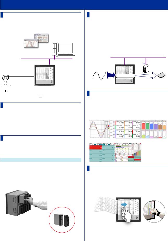
Overview
The GX/GP is a paperless recorder that can display measured data in real time on its touch screen and save the data in an SD memory card.
GX/GP configuration and real-time monitoring on a Web browser
Displaying data on
Universal Viewer
Ethernet
GX/GP
A variety of

 signal inputs
Redundant measured data
on internal memory and external media  SD memory card
A Variety of Source Signals
The GX/GP can connect to DC voltage, TC, RTD, and ON/OFF inputs and measure temperature, flow rate, and other parameters. The GX/GP acquires data by sampling input signals at the set scan interval. The shortest scan interval is 100 ms. Up to four alarm conditions can be specified on each measurement channel.
Expandable Module Construction
The I/O section is modular, so you can configure your system according to the input types and number of measurement points.
Modules
Model |
Name |
Channels |
GX90XA |
Analog input module |
10 |
GX90XD |
Digital input module |
16 |
GX90YD |
Digital output module |
6 |
•Up to 10 modules can be installed in the GX20/GP20.
•Up to 3 modules can be installed in the GX10/GP10.
•Different modules can coexist.
Data Storage
There are two ways to store data. One way is to record measured data at all times (display data and event data). The other way is to record only when events, such as alarms, occur (event data). Measured data is saved to the internal memory at the specified interval. Data in the internal memory can be saved to the SD memory card automatically or manually. Measured data can
be transferred automatically to an FTP server over an Ethernet connection.
Auto data transfer to FTP server |
Ethernet |
|
GX/GP |
FTP server |
|
Internal memory |
|
|
Signal input |
|
SD Memory |
|
card |
|
A Variety of Display Functions
Measured data can be displayed in groups as trend waveforms, values, and bar graphs. There is also an overview display that you can monitor all channels on a single screen.
Trend |
|
Digital |
Bar graph |
|
|
|
|
|
|
Overview |
Multi panel |
|
|
|
|
Touch Screen
The GX/GP touch screen enables intuitive operation. You can tap the icons of setup and operation items as well as scroll and zoom in on and out of waveforms by directly touching the screen. In addition, when you are working on-site, you can operate the GX/GP with your gloves on.
Detachable module terminal block
Maintenance is easy!
8 |
IM 04L51B01-02EN |

Functional Overview
Touch Operations
Tap
Touch the screen with a pen or finger.
Drag
Touch the screen with a pen or finger and move.
Flick
Wipe a pen or finger across the screen.
Pinch apart/together
Touch the screen with two fingers and move them apart or together.
Freehand Messages
You can use the touch pen or your finger to write text and draw marks freely in the waveform area. The messages that you write can easily be displayed from information displays such as the message summary and memory summary.
Versatile Network Functions and Software
The Ethernet interface enables you to monitor the GX/ GP from a Web browser. E-mails can be sent through this interface when alarms and other events occur.
In addition, you can use the Modbus protocol to read data from other devices on the network and display it. As for the software, Universal Viewer can be used to view measured data and convert the data into other data formats.
Internet Explorer 6/8
Seamless remote monitoring
on a Web browser
Ethernet
Other Functions
Math function |
Expressions can be assigned to |
(/MT option) |
math channels to perform various |
|
computations. |
FAIL output |
This function transmits alarms when |
(/FL option) |
the GX/GP fails. |
Security function |
You can allow only registered users |
|
to use the GX/GP. In addition, certain |
|
operations can be prohibited. |
Remote control |
This function executes specified |
|
operations by combining input modules |
|
and the event action function. |
IM 04L51B01-02EN |
9 |
Functional Overview
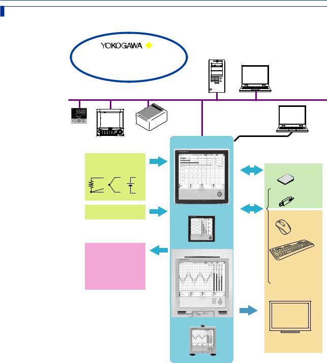
System Configuration
You can configure a GX/GP system as shown below.
Web site |
|
• Download PC software |
|
• Download user’s manuals |
PC |
Ethernet
Temperature |
Network |
Controller |
|
Recorder |
printer |
|
PC |
|
Serial communication* |
GX20 |
RS-232, RS-422/485 |
Signal input |
|
|
RTD TC/DCV DI |
|
SD memory card |
|
|
USB memory |
|
|
USB port* |
Remote input |
GX10 |
Mouse |
|
|
|
|
|
keyboard |
Alarm output |
GP20 |
|
Bar code reader FAIL/status output* 

Monitor*
GP10
* Option
(GX20/GP20 only)
10 |
IM 04L51B01-02EN |
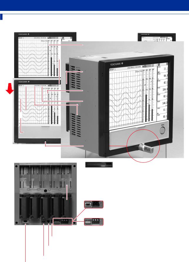
Component Names
GX20/GX10
GX20 front panel |
GX10 front panel |
LCD
Shows the trend display and other displays and the setup screen
 START/STOP key
Starts and stops recording
MENU key
 Power switch Front door
Press this once to show a menu |
|
for accessing various screens. |
GX10 rear panel |
|
|
Stylus pen (touch pen) |
|
USB port (/UH option)
USB2.0 compliant. Connect a USB memory device, mouse, keyboard, etc.
 SD memory card slot
SD memory card (up to 32 GB)
Format: FAT32 or FAT16
A 1 GB card is included.
 MENU key
Alarms are indicated with a red
LED.
GX20 rear panel
Front door lock
mechanism
A front door is locked/unlocked
by a slide at the bottom. Lock 
Use an off-the-shelf door lock key.
 I/O module slot
GX10, GP10: slots (0 to 2)
GX20, GP20: 10 slots (0 to 9)
 I/O module
Connect I/O signals.
 Power inlet (GP10/GP20)
 Serial port (/C2 option)
RS-232 terminal
Power supply terminal and protective  ground terminal (GX10/GX20)
 Serial port (/C3 option)
RS-422/485 terminal
 USB port (/UH option)
USB 2.0 compliant. Connect a USB memory device, mouse, keyboard, etc.
 Ethernet port
10BASE-T/100BASE-TX port
 FAIL output terminal (/FL option)
 VGA output connector (/D5 option)
Connects to an external monitor
IM 04L51B01-02EN |
11 |
Component Names
GP20/GP10
GP20 front |
GP20 rear |
Handle
|
|
|
Power inlet |
|
|
|
|
|
|
|
|
|
|
||
|
|
|
|
|
|||
|
|
|
|
|
|
|
|
|
|
|
|
Feet |
|||
GP10 front |
|
GP10 rear |
|||||
|
|
Handle |
|||||
|
|
|
|
|
|
|
|
|
|
|
|
|
|
|
|
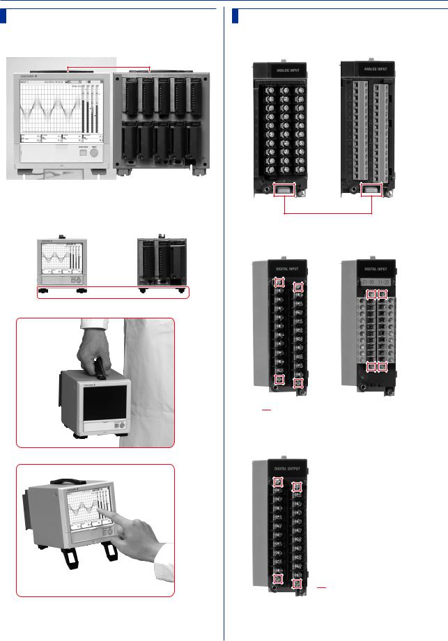
GX90XA/GX90XD/GX90YD
GX90XAAnalog Input Module
M3 screw terminal |
Clamp terminal |
Terminal block release levers
GX90XD Digital Input Module
M3 screw terminal |
Clamp terminal |

 Terminal block attachment screws
GX90YD Digital Output Module
M3 screw terminal

 Terminal block attachment screws
12 |
IM 04L51B01-02EN |
Loading...