


 Loading...
User’s |
Models UM351/UM331 |
Manual |
|
|
Digital Indicator with Alarms |
|
User’s Manual |
IM 05F01D12-41E
IM 05F01D12-41E
4th Edition

Blank Page

<Toc> <Rev> |
i |
Introduction
Thank you for purchasing the UM351/UM331 digital indicator with alarms.
■ How to Use the Manuals
Purpose |
|
Title |
Description |
|
|
|
|
Setup |
1. |
Installation |
Describes the tasks (installation, wiring, and others) required |
|
|
|
to make the indicator ready for operations. |
Basic operation |
2. |
Initial Settings |
Describes examples of setting PV input types, and alarm |
|
|
|
types. Making settings described herein allows you to carry |
|
|
|
out basic monitoring. |
|
|
|
|
Operating |
3. |
Operations |
Describes examples of setting alarm setpoints, as well as |
procedures |
4.1 Troubleshooting |
key operation necessary to run the indicator. |
|
and troubleshooting |
|
|
|
Brief operation |
5. |
Parameters |
Contains the parameter map used as a guideline for setting |
and setpoint recording |
|
|
parameters and lists of parameters for recording user settings. |
■Regarding This User’s Manual
(1)This manual should be provided to the end user. Keep an extra copy or copies of the manual in a safe place.
(2)Read this manual carefully to gain a thorough understanding of how to operate this product before starting operation.
(3)This manual describes the functions of this product. Yokogawa Electric Corporation (hereinafter simply referred to as Yokogawa) does not guarantee the application of these functions for any particular purpose.
(4)Under absolutely no circumstances may the contents of this manual, in part or in whole, be transcribed or copied without permission.
(5)The contents of this manual are subject to change without prior notice.
(6)Every effort has been made to ensure that the details of this manual are accurate. However, should any errors be found or important information be omitted, please contact your nearest Yokogawa representative or our sales office.
Media No. IM 05F01D12-41E (CD) |
4th Edition : May 2006 (YK) |
IM 05F01D12-41E 4th Edition: May 31, 2006-00 |
All Rights Reserved Copyright © 2003, Yokogawa Electric Corporation |
|
|

<Toc> <Rev> |
ii |
■ Safety Precautions
The following symbol is indicated on the indicator to ensure safe use.
This symbol on the indicator indicates that the operator must refer to an explanation in the user’s manual in order to avoid the risk of injury or death of personnel or damage to the
 instrument. The manual describes how the operator should exercise special care to avoid CAUTION electric shock or other dangers that may result in injury or loss of life.
The following symbols are used in the hardcopy user’s manuals and in the user’s manual supplied on the CD-ROM.
 NOTE
NOTE
Indicates that operating the hardware or software in a particular manner may damage it or result in a system failure.
 IMPORTANT
Draws attention to information that is essential for understanding the operation and/or features of the indicator.
■Force Majeure
(1)Yokogawa assumes no liability to any party for any loss or damage, direct or indirect, caused by the use or any unpredictable defect of the product.
(2)No portion of the software supplied by Yokogawa may be transferred, exchanged, leased or sublet for use by any third party without the prior permission of Yokogawa.
(3)Be sure to use the spare parts approved by Yokogawa when replacing parts or consumables.
(4)Use this software with one specified computer only. You must purchase another copy of the software for use on each additional computer.
(5)Copying this software for purposes other than backup is strictly prohibited.
(6)Store the floppy disk(s) (original medium or media) containing this software in a secure place.
IM 05F01D12-41E 4th Edition: May 31, 2006-00

<Toc> <Rev> |
iii |
■Regarding Protection, Safety, and Prohibition Against Unauthorized Modification
(1)In order to protect the product and the system controlled by it against damage and ensure its safe use, make certain that all of the instructions and precautions relating to safety contained in this document are strictly adhered to. Yokogawa does not guarantee safety if products are not handled according to these instructions.
(2)Modification of the product is strictly prohibited.
(3)Reverse engineering such as the disassembly or decompilation of software is strictly prohibited.
IM 05F01D12-41E 4th Edition: May 31, 2006-00

Blank Page

<Int> <Rev> |
Toc-i |
Models UM351/UM331
Digital Indicator with Alarms
User’s Manual
IM 05F01D12-41E 4th Edition
CONTENTS
Introduction |
........................................................................................................... |
i |
|
1. |
Installation .............................................................................................. |
1-1 |
|
|
1.1 .................................................................................. |
Model and Suffix Codes |
1-1 |
|
1.2 ................................................................................................... |
How to Install |
1-2 |
|
1.3 .................................................................................... |
How to Connect Wires |
1-5 |
|
1.4 ................................................................................ |
Hardware Specifications |
1-7 |
|
1.5 ............................................................................ |
Terminal Wiring Diagrams |
1-12 |
2. |
Initial Settings ......................................................................................... |
2-1 |
|
|
2.1 ................................................... |
Names and Functions of Front Panel Parts |
2-2 |
|
2.2 ......................................... |
Setting PV Input Type (Setting First at Power - on) |
2-3 |
|
2.3 ................................................................................. |
Changing PV Input Type |
2-7 |
|
2.4 ..................................................................................... |
Changing Alarm Type |
2-9 |
|
2.5 ............................................................ |
Setting Hysteresis in Alarm Setpoint |
2-11 |
2.6Setting the PV display color changing function “Active Color PV Display”... 2-12
|
2.7 |
Setting the High Limit and Low limit for PV Color change ......................... |
2-13 |
|
3. |
Operations .............................................................................................. |
|
3-1 |
|
|
3.1 |
Monitoring-purpose Operating Display Available during Operation ........... |
3-1 |
|
|
3.2 |
Setting Alarm Setpoints .................................................................................. |
3-2 |
|
4. |
Troubleshooting and Maintenance ........................................................ |
4-1 |
||
|
4.1 |
Troubleshooting .............................................................................................. |
4-1 |
|
|
4.2 |
Maintenance .................................................................................................... |
4-4 |
|
|
|
4.2.1 |
Cleaning ........................................................................................... |
4-4 |
|
|
4.2.2 |
Replacing Brackets ........................................................................... |
4-4 |
|
|
4.2.3 |
Attaching Terminal Cover .................................................................. |
4-4 |
|
|
4.2.4 |
Replacing Parts with a Limited Service Life ....................................... |
4-6 |
5. |
Parameters .............................................................................................. |
|
5-1 |
|
|
5.1 |
Parameter Map ................................................................................................ |
5-1 |
|
|
5.2 |
Lists of Parameters ......................................................................................... |
5-2 |
|
Revision Information ............................................................................................ |
|
i |
||
IM 05F01D12-41E 4th Edition: May 31, 2006-00

Blank Page

<Toc> |
<1. Installation> |
1-1 |
1.Installation
This chapter describes installation, wiring, and other tasks required to make the indicator ready for operation.
1.1Model and Suffix Codes
Before using the indicator, check that the model and suffix codes match your order.
Model |
|
Suffix Code |
Description |
|
|
|
|
|
|
UM351 |
|
|
|
Digital indicator with Alarms (provided with retransmission output and 15 |
UM331 |
|
|
|
V DC loop power supply as standard) |
Type |
|
-0 |
|
Standard type with three alarms |
|
-3 |
|
Standard type with three alarms (with 24 V DC loop power supply) |
|
|
|
|
||
|
|
|
|
|
|
|
|
0 |
None |
Optional functions |
|
1 |
With communication and additional alarm-4 |
|
|
|
|
2 |
With additional alarm-4 |
|
|
|
|
|
Check that the following items are provided: |
|
|
• Digital indicator with alarms (of ordered model) .................... |
1 |
|
• |
Brackets (mounting hardware) ............................................. |
1 pair |
• |
Unit label.............................................................................. |
1 |
• |
User’s Manuals .................................................................... |
3 (A2 size) |
• |
User’s Manuals |
|
|
“Setting/Explanation of Active Color PV Display ................... |
1 (A3 size) |
• User’s Manual (Reference) (CD-ROM version)
(only for indicators with optional communication functions) ... 1
IM 05F01D12-41E 4th Edition: May 31, 2006-00
<Toc> |
<1. Installation> |
1-2 |
1.2How to Install
 NOTE
NOTE
To install the indicator, select a location where:
1.no one may accidentally touch the terminals,
2. |
mechanical vibrations are minimal, |
|
|
|
|
|
|
|
|
|
|
|
|
3. |
corrosive gas is minimal, |
|
|
150 mm |
|
|
|
|
|
|
|
||
|
|
|
|
|
|
|
|
|
|
|
|
||
|
|
|
|
|
|
|
|
|
|
|
|
||
4. |
temperature can be maintained at about 23 C and |
|
|
|
|
|
|
|
|
|
|
|
|
|
|
|
|
|
|
|
|
|
|
|
|
||
|
the fluctuation is minimal, |
|
150 mm |
|
|
|
|
|
|
|
150 |
mm |
|
|
|
|
|
|
|
|
|
150 mm |
|
||||
|
|
|
|
|
|
|
|
|
|
||||
5. |
no direct radiant heat is present, |
|
|
|
|
|
|
|
|
|
|
|
|
|
|
|
|
|
|
|
|
|
|
|
|
||
6.no magnetic disturbances are caused,
7.no wind blows against the terminal board (reference junction compensation element),
8.no water is splashed,
9.no flammable materials are around,
Never place the indicator directly on flammable items or equipment.
If the indicator has to be installed close to flammable items or equipment, be sure to provide shielding panels all around the indicator, at least 150 mm away from every side; the panels should be made of either 1.43 mm-thick metal-plated steel plates or 1.6 mm-thick uncoated steel plates.
 NOTE
NOTE
Never touch the opening at the bottom of the case. It is to be used in the factory at shipping.
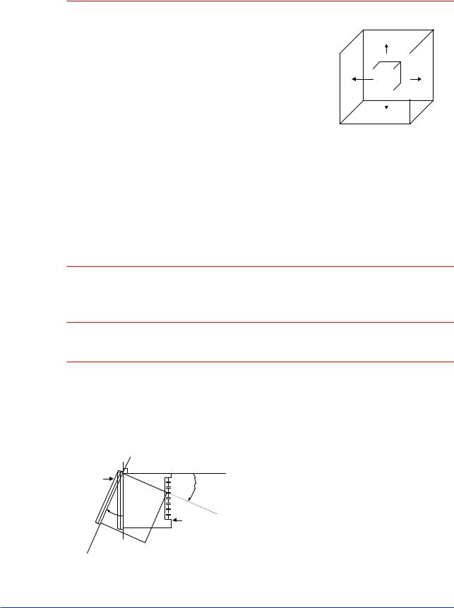
● Installation Position
Install the indicator at an angle within 30 from horizontal with the front panel facing upward. Do not install it facing downward. The position of right and left sides should be horizontal.
Front panel
of indicator Must not exceed 30
30 |
Rear of |
|
indicator |
||
|
IM 05F01D12-41E 4th Edition: May 31, 2006-00

<Toc> |
<1. Installation> |
1-3 |
■ External Dimensions and Panel Cutout Dimensions |
|
|
UM351 |
Unit: mm |
|
96 |
11 |
100 |
Large bracket |
96 |
91.8 |
112 |
Small bracket 1 to 10 mm (Panel thickness)
General installation |
Side-by-side close installation |
117 min. |
[(N-1) 96+92]+00.8 |
+0.8 92 0
(53) |
145 min. |
|
92+00.8
92+00.8 (25)
"N" stands for the number of indicators to be installed.
However, the measured value applies if N 5.
UM331 |
Unit: mm |
|
112 |
||
|
|
Small bracket |
91.8 |
|
Small bracket |
|
|
96 |
|
48 |
100 |
|
|
11 |
1 to 10 mm (Panel thickness) |
|
|
Front of indicator
General installation
145 min.
(25) |
70 min. |
|
|
|
|
|
|
|
45+00.6
92+00.8 |
|
(53) |
|
|
|
IM 05F01D12-41E 4th Edition: May 31, 2006-00
<Toc> |
<1. Installation> |
1-4 |
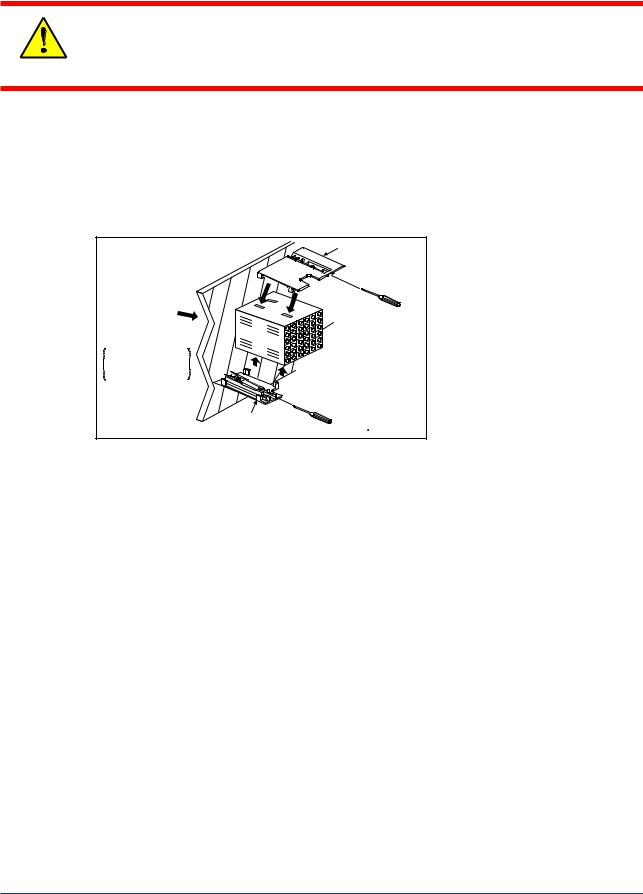
■ How to Install
Turn off the power to the indicator before installing it on the panel because there is a possibility of electric shock.
CAUTION
After opening the mounting hole on the panel, follow the procedures below to install the indicator:
1.Insert the indicator into the opening from the front of the panel so that the terminal board on the rear is at the far side.
2.Set the brackets in place on the top and bottom of the indicator as shown in the figure below, then tighten the screws of the brackets. Take care not to overtighten them.
Direction to insert the indicator
Insert the indicator into the opening at the front of the panel.
Large bracket
Panel |
(top mounting hardware) |
Terminal board
Insert a screwdriver into the brackets to tighten the screws.
Small bracket |
Recommended |
tightening torque |
|
(bottom mounting hardware) |
:0.4N m |
Note: Right and left mounting for UM331.
IM 05F01D12-41E 4th Edition: May 31, 2006-00
<Toc> |
<1. Installation> |
1-5 |
1.3How to Connect Wires
1)Before carrying out wiring, turn off the power to the indicator and check that the cables
to be connected are not alive with a tester or the like because there is a possibility of electric shock.
CAUTION 2) Wiring must be carried out by personnel who have basic electrical knowledge and practical experience.
 NOTE
NOTE
1)Provide power from a single-phase instrument power supply. If there is a lot of noise in the power line, insert an insulating transformer into the primary side of the line and use a line filter (recommended part: ZAC2205-00U from TDK) on the secondary side.
As a countermeasures against noise, do not place the primary and secondary power cables close to each other.
2)For thermocouple input, use shielded compensating lead wires for wiring. For RTD input, use shielded wires that have low conductor resistance and cause no significant differences in resistance between the three wires.
The cables to be used for wiring, terminal specifications, and recommended parts are as shown below.
3)Alarm output relays have a life of 100,000 times that of the resistance load, use auxiliary relays to turn on/off a load.
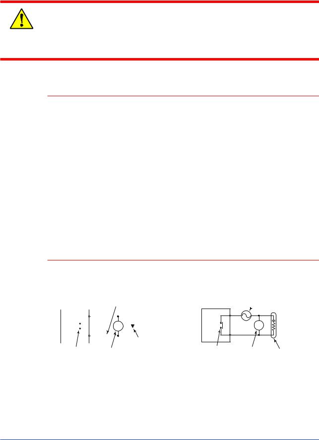
4)The use of inductance (L) loads such as auxiliary relays, motors and solenoid valves causes malfunction or relay failure; always insert a CR filter for use with alternating current or a diode for use with direct current, as a spark-removal surge suppression circuit, into the line in parallel with the load.
5)When there is possibility of being struck by external lightening surge, use the arrester to protect the instrument.
■ For DC Relay Wiring |
■ For AC Relay Wiring |
UM351/UM331 |
External DC power supply |
||
|
|
|
|
|
Relay |
|
|
|
|
|
|
|
|
|
|
R |
|
|
Diode |
|
|
|
|
|
|
|
|
|
|
||
|
|
|
|
|
|
|
|
|
|
|
|
|
|
|
|
|
|
|
|
|
|
|
|
|
|
|
|
|
|
|
|
|
|
|
(Mount it directly |
UM’s contact |
|
|
|
|
|
|
|||||
|
|
Relay |
|
|
|
to the relay coil |
|||||
|
|
|
|
|
|
|
|||||
|
(Use one with a relay coil |
|
|
|
terminal (socket).) |
||||||
|
rating less than the UM’s |
|
|
|
|
||||||
|
|
contact rating.) |
|
|
|
|
|||||
UM351/UM331  External AC power supply
|
|
R |
UM’s contact |
Relay |
CR filter |
|
||
(Use one with a relay coil |
(Mount it directly |
|
rating less than the UM’s |
to the relay coil |
|
|
contact rating.) |
terminal (socket).) |
IM 05F01D12-41E 4th Edition: May 31, 2006-00
<Toc> |
<1. Installation> |
1-6 |
|||||||||
● Cable Specifications and Recommended Cables |
|
||||||||||
|
|
|
|
|
|
|
|
|
|
|
|
|
Purpose |
Name and Manufacturer |
|
||||||||
|
|
|
|
|
|
|
|
|
|
|
|
|
Power supply, grounding, relay contact outputs |
600 V PVC insulated wires, JIS C 3307, 0.9 to 2.0 mm2 |
|
||||||||
|
Thermocouple |
Shielded compensating lead wires, JIS C 1610, |
|
X- |
|
- |
|
- |
|
|
|
|
|
|
|
|
|
||||||
|
|
|
|
|
|
||||||
|
|
(See Yokogawa Electric's GS 6B1U1-E.) |
|
||||||||
|
|
|
|
|
|
|
|
|
|
|
|
|
RTD |
Shielded wires (three conductors), UL2482 (Hitachi Cable) |
|
||||||||
|
|
|
|
|
|
|
|
|
|
|
|
|
Other signals |
Shielded wires |
|
||||||||
|
|
|
|
|
|
|
|
|
|
|
|
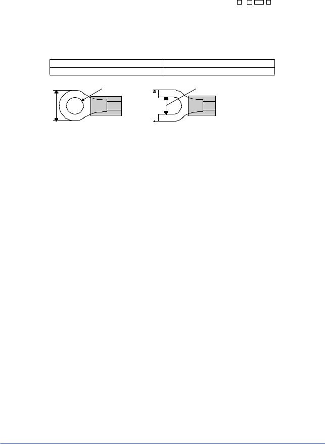
● Recommended Terminal Lugs
7 m m o r l e s s
Applicable wire size
0.3 to 1.65 mm2
3 . 7 m m
or
Tightening torque
0.8 N·m or less
3 . 7 m m
7 m m o r l e s s
● Terminal Covers (Optional parts)
Target Model |
Part Number |
Sales Unit |
|
|
|
UM351 |
T9115YD |
1 |
|
|
|
UM331 |
T9115YE |
1 |
|
|
|
IM 05F01D12-41E 4th Edition: May 31, 2006-00

<Toc> |
<1. Installation> |
1-7 |
1.4Hardware Specifications
PV Input Signals
•Number of inputs: 1 (terminals 11 - 12 - 13 )
•Input type: Universal input system. The input type can be selected with the software.
•Sampling period: 250 ms
•Burnout detection: Functions at TC, RTD, standard signal (0.4 to 2 V or 1 to 5 V) Upscale, downscale, and off can be specified.
For standard signal, burnout is determined to have occurred if it is 0.1 V or less.
•Input bias current: 0.05 A (for TC or RTD b-terminal)
•Measurement current (RTD): About 0.13 mA
•Input resistance: 1 M or more for thermocouple or mV input About 1 M for DC voltage input
•Allowable signal source resistance: 250 or less for thermocouple or mV input Effects of signal source resistance: 0.1 V/ or less
2 k or less for DC voltage input
Effects of signal source resistance: About 0.01%/100 V
•Allowable wiring resistance: for RTD input
Maximum 150 /wire: Conductor resistance between three wires should be equal However, 10 /wire for a maximum range of -150.0 to 150.0 C.
Wire resistance effect: 0.1 C/10
•Allowable input voltage: 10 V DC for thermocouple, mV, or RTD input20 V DC for DC voltage input
•Noise rejection ratio: 40 dB (50/60 Hz) or more in normal mode 120 dB (50/60 Hz) or more in common mode
•Reference junction compensation error: 1.0 C (15 to 35 C)1.5 C (0 to 15 C, 35 to 50 C)
•Applicable standards: JIS, IEC, DIN (ITS-90) for thermocouples and RTD
Loop Power Supply
Power is supplied to a two-wire transmitter.
(15 V DC: terminals 16 - 17 ; 24 V DC: terminals 21 - 22 )
A resistor (10 to 250 ) connected between the indicator and transmitter converts a current signal into a voltage signal, which is then read via the PV input terminal. Supply voltage: 14.5 to 18.0 V DC, max. 21 mA (provided with a protection circuit against a field short-circuit); 21.6 to 28.0 V DC, max. 30 mA (only for models with 24 V DC loop power supply)
IM 05F01D12-41E 4th Edition: May 31, 2006-00

<Toc> |
<1. Installation> |
1-8 |
Retransmission Output
Outputs the PV value.
Either the retransmission output or the loop power supply can be used with terminals
16- 17 .
•Number of outputs: 1 (terminals 16 - 17 )
•Output signal: 4-20 mA DC
•Load resistance: 600 or less
•Output accuracy: 0.3% of span under standard operating conditions (23 2 C, 55 10% RH, power frequency of 50/60 Hz)
Contact Inputs
•Purpose: Resetting of PV peak and bottom values
•Number of inputs: 1
•Input type: Non-voltage contact or transistor open collector input
•Input contact rating: 12 V DC, 10 mA or more
•On/off determination: For non-voltage contact input, contact resistance of 1 k or less is determined as “on” and contact resistance of 20 k or more as “off.”
For transistor open collector input, input voltage of 2 V or less is determined as “on” and leakage current must not exceed 100 A when “off.”
•Minimum status detection hold time: About 1 second
Contact Outputs
•Purpose: Alarm output, FAIL output, and others
•Number of outputs: 4 (Max).
•Relay contact rating for Alarm 1 to 3: 240 V AC, 1 A, or 30 V DC, 1 A; 1a
•Relay contact rating for Alarm 4: 250 V AC, 3 A, or 30 V DC, 3 A (resistance load) 3 terminals (NC, NO, Common); 1c, (FAIL output : 1b)
Display Specifications
•PV display: 4-digit, 7-segment red LED display, character height of 20 mm (for both UM351 and UM331)
•Setpoint display: 4-digit, 7-segment, red LEDs, character height of 9.3 mm (for both UM351 and UM331)
•Status indicating lamps: LEDs
Safety and EMC Standards
•Safety: Complies with IEC/EN61010-1 (CE), approved by C22.2 No.61010-1, approved by UL508.
Installation category : CAT. II Pollution degree : 2 (IEC/EN61010-1, C22.2 No.61010- 1)
Measurement category : I (CAT. I : IEC/EN61010-1)
Rated measurement input voltage : 10V DC max.(across terminals), 300V AC max.(across ground)
IM 05F01D12-41E 4th Edition: May 31, 2006-00

<Toc> |
<1. Installation> |
1-9 |
Rated transient overvoltage : 1500V (Note)
Note : It is a value on the safety standard which is assumed by IEC/EN61010-1 in Measurement category I, and is not the value which guarantees an apparatus performance.
This equipment has Measurement category I, therefore do not use the equipment for measurements within Measurement categories II, III and IV.
CAUTION
Measurement category |
Description |
Remarks |
|
|
|
|
|
1 |
CAT.1 |
For measurements performed on circuits not directly connected to MAINS. |
|
|
|
|
|
2 |
CAT.2 |
For measurements performed on circuits directly connected to the low voltage installation. |
Appliances, portable equipments, etc. |
3 |
CAT.3 |
For measurements performed in the building installation. |
Distribution board, circuit breaker, etc. |
4 |
CAT.4 |
For measurements performed at the source of the low-voltage installation. |
Overhead wire, cable systems, etc. |
Internal Wiring |
2 |
|
3 |
T |
|
Entrance 4 |
1 |
|
Cable |
|
|
|
|
|
Outlet |
|
|
•EMC standards: Complies with EN61326, EN61000-3-2, EN61000-3-3 and EN55011 (CE).
AS/NZS 2064 compliant (C-Tick). Class A Group 1.
The instrument continues to operate at a measuring accuracy of within 20% of the range during tests.
Construction, Installation, and Wiring
•Construction: Dust-proof and drip-proof pront panel conforming to IP55. For side-by- side close installation the indicator loses its dust-proof and drip-proof protection.
•Material: ABS resin and polycarbonate
•Case color: Black
•Weight: About 1 kg or less
•Dimensions:
UM351 96 (W) 96 (H) 100 (depth from panel face) mm UM331 96 (W) 48 (H) 100 (depth from panel face) mm
•Installation: Panel-mounting type. With top and bottom (or right and left) mounting hardware (1 each)
•Panel cutout dimensions:
UM351 920+0.8 (W) 920+0.8 (H) mm UM331 920+0.8 (W) 450+0.6 (H) mm
•Installation position: Up to 30 upward facing (not designed for facing downward)
•Wiring: M3.5 screw terminals (for signal wiring and power/ground wiring as well)
IM 05F01D12-41E 4th Edition: May 31, 2006-00

<Toc> |
<1. Installation> |
1-10 |
Power Supply Specifications
•Power supply: Rated voltage of 100 to 240 V AC ( 10%), 50/60 Hz
•Power consumption: Max. 20 VA (8.0 W max.)
• Internal fuse rating: 250 VAC, 1.6A time-lug fuse
•Data backup: Non-volatile memory (can be written to up to 100,000 times)
•Withstanding voltage
-Between primary terminals* and secondary terminals**: At least 1500 V AC for 1 minute
-Between primary terminals* and grounding terminal: At least 1500 V AC for 1 minute
-Between grounding terminal and secondary terminals**: At least 1500 V AC for 1 minute
-Between secondary terminals**: At least 500 V AC for 1 minute
*Primary terminals indicate power terminals and relay output terminals
**Secondary terminals indicate analog I/O signal, and contact input terminals
•Insulation resistance: 20 M or more at 500 V DC between power terminals and grounding terminal
•Grounding: Class D grounding (grounding resistance of 100 or less)
Signal Isolations
•PV input terminals: Isolated from other input/output terminals. Not isolated from internal circuit.
•15 V DC loop power supply terminals: Not isolated from 4-20 mA analog output. Isolated from other input/output terminals and internal circuit.
•24 V DC loop power supply terminals: Isolated from 4-20 mA analog output terminals, other input/output terminals and internal circuit.
•4-20 mA analog output terminals (for retransmission): Not isolated from 15 V DC loop power supply. Isolated from other input/output terminals and internal circuit.
•Contact input terminals: Not isolated from communication terminals. Isolated from other input/output terminals and internal circuit.
•Relay contact output terminals: Not isolated between relay contact output terminals. Isolated from other input/output terminals and internal circuit.
•RS-485 communication terminals: Not isolated from contact input terminals. Isolated from other input/output terminals and internal circuit.
•Power terminals: Isolated from other input/output terminals and internal circuit.
•Grounding terminals: Isolated from other input/output terminals and internal circuit.
IM 05F01D12-41E 4th Edition: May 31, 2006-00
Loading...