


|
|
Operation |
UT35A-L |
Guide |
Digital Indicating Controller (Limit Control Type) |
|
Operation Guide |
IM 05P04D41-11EN |
Installation and Wiring |
|
|
|
1st Edition : Jul. 2011 |
This operation guide describes installation, wiring, and other tasks required to make the controller ready for operation.
Contents
1.Safety Precautions
2.Model and Suffix Codes
3.How to Install
4.Hardware Specifications
5.How to Connect Wires
6.Terminal Wiring Diagrams
Introduction
Thank you for purchasing the UT35A-L Digital Indicating Controller.
This operation guide describes the basic operations of the UT35A-L. The guide should be provided to the end user of this product.
Be sure to read this operation guide before using the product in order to ensure correct operation.
For details of each function, refer to the electronic manual. Before using the product, refer to the table of Model and Suffix Codes to make sure that the delivered product is consistent with the model and suffix codes you ordered. Also make sure that the following items are included in the package.
• Digital Indicating Controller (the model you ordered).............................. |
x1 |
• Set of Brackets........................................................................................ |
x1 |
• Unit Label (L4502VZ)............................................................................... |
x1 |
• Tag Label (L4502VE)............................................................................... |
x1 |
(Only when ordered.) |
|
• Operation Guide (this document)............................................................. |
x5 (A3 size) |
(Installation and Wiring, Initial Settings, Operations, and Parameters)
•Target Readers
This guide is intended for the following personnel;
•Engineers responsible for installation, wiring, and maintenance of the equipment.
•Personnel responsible for normal daily operation of the equipment.
1.Safety Precautions
The following symbol is used on the instrument. It indicates the possibility of injury to the user or damage to the instrument, and signifies that the user must refer to the user’s manual for special instructions. The same symbol is used in the user’s manual on pages that the user needs to refer to, together with the term “WARNING” or “CAUTION.”
Calls attention to actions or conditions that could cause serious or fatal injury to the user, and indicates precautions that should be
WARNING taken to prevent such occurrences.
Calls attention to actions or conditions that could cause injury to the user or damage to the instrument or property and indicates pre-
cautions that should be taken to prevent such occurrences.
CAUTION
 AC
AC
 AC/DC
AC/DC
The equipment wholly protected by double insulation or reinforced insulation.
Functional grounding terminals
(Do not use this terminal as a protective grounding terminal).
Note
Identifies important information required to operate the instrument.
n Warning and Disclaimer
(1)YOKOGAWA makes no warranties regarding the product except those stated in the WARRANTY that is provided separately.
(2)The product is provided on an "as is" basis. YOKOGAWA assumes no liability to any person or entity for any loss or damage, direct or indirect, arising from the use of the product or from any unpredictable defect of the product.
n Safety, Protection, and Modification of the Product
(1)In order to protect the system controlled by this product and the product itself, and to ensure safe operation, observe the safety precautions described in the user’s manual. Use of the instrument in a manner not prescribed herein may compromise the product's functions and the protection features inherent in the device. We assume no liability for safety, or responsibility for the product's quality, performance or functionality should users fail to observe these instructions when operating the product.
(2)Installation of protection and/or safety circuits with respect to a lightning protector; protective equipment for the system controlled by the product and the product itself; foolproof or fail-safe design of a process or line using the system controlled by the product or the product itself; and/or the design and installation of other protective and safety circuits are to be appropriately implemented as the customer deems necessary.
(3)Be sure to use the spare parts approved by YOKOGAWA when replacing parts or consumables.
(4)This product is not designed or manufactured to be used in critical applications that directly affect or threaten human lives. Such applications include nuclear power equipment, devices using radioactivity, railway facilities, aviation equipment, air navigation facilities, aviation facilities, and medical equipment. If so used, it is the user’s responsibility to include in the system additional equipment and devices that ensure personnel safety.
(5)Modification of the product is strictly prohibited.
(6)This product is intended to be handled by skilled/trained personnel for electric devices.
(7)This product is UL Recognized Component. In order to comply with UL standards, end-products are necessary to be designed by those who have knowledge of the requirements.
|
• Power Supply |
|
Ensure that the instrument’s supply voltage matches the voltage |
WARNING |
of the power supply before turning ON the power. |
• Do Not Use in an Explosive Atmosphere |
|
|
Do not operate the instrument in locations with combustible |
|
or explosive gases or steam. Operation in such environments |
|
constitutes an extreme safety hazard. Use of the instrument in |
|
environments with high concentrations of corrosive gas (H2S, |
|
SOX, etc.) for extended periods of time may cause a failure. |
|
• Do Not Remove Internal Unit |
|
The internal unit should not be removed by anyone other than |
|
YOKOGAWA's service personnel. There are dangerous high |
|
voltage parts inside. Additionally, do not replace the fuse by |
|
yourself. |
|
• Damage to the Protective Construction |
|
Operation of the instrument in a manner not specified in the |
|
user’s manual may damage its protective construction. |
|
|
|
|
|
|
|
This instrument is an EMC class A product. In a domestic environ- |
|
ment this product may cause radio interference in which case the |
CAUTION |
user needs to take adequate measures. |
n Accessories (sold separately)
The following is an accessory sold separately.
• LL50A Parameter Setting Software
Model |
Suffix code |
Description |
LL50A |
-00 |
Parameter Setting Software |
•Terminal Cover Model: UTAP001
•User’s Manual (A4 size)
Note: User’s Manual can be downloaded from a website.
•User’s Manual (CD-ROM), Model: UTAP003
Note: Contains all manuals.
•Brackets
Part number: L4502TP (2 pcs for upper and lower sides)
2.Model and Suffix Codes
n UT35A-L
|
|
|
|
|
|
|
|
|
[Style: S6] |
|
|
|
|
|
|
|
|
|
|
|
|
|
|
|
|
|
|
Optional |
|
Model |
|
|
Suffix code |
|
suffix |
Description |
|||
|
|
|
|
|
|
|
|
code |
|
UT35A |
|
|
|
|
|
|
|
|
Digital Indicating Controller |
|
|
|
|
|
|
|
|
(provided with retransmission output, 2 DIs, and 3 |
|
|
|
|
|
|
|
|
|
|
DOs) (Power supply: 100-240 V AC) |
Type 1: |
-L |
|
|
|
|
|
|
|
|
Basic |
|
|
|
|
|
|
|
Limit control type |
|
control |
|
|
|
|
|
|
|
|
|
Type 2: |
|
0 |
|
|
|
|
|
|
Always "0" |
Functions |
|
|
|
|
|
|
|
||
|
|
|
|
|
|
|
|
|
|
Type 3: Open |
|
0 |
|
|
|
|
None |
||
|
1 |
|
|
|
|
RS-485 communication (Max.38.4 kbps, 2-wire/4-wire) |
|||
networks |
|
|
|
|
|
|
|
||
|
|
|
2 |
|
|
|
|
Ethernet communication (with serial gateway function) |
|
|
|
|
|
|
|
|
|
||
Display language |
|
-1 |
|
|
|
English |
|||
Case color |
|
|
|
0 |
|
|
White (Light gray) |
||
|
|
|
|
|
1 |
|
|
Black (Light charcoal gray) |
|
|
|
|
|
|
|
||||
Fixed code |
|
|
|
|
|
|
-00 |
|
Always "-00" |
Optional suffix codes |
|
/DC |
Power supply 24 V AC/DC |
||||||
n Waste Electrical and Electronic Equipment (WEEE), Directive 2002/96/EC
This is an explanation of how to dispose of this product based on Waste Electrical and Electronic Equipment (WEEE), Directive 2002/96/EC. This directive is only valid in the EU.
Marking
This product complies with the WEEE Directive (2002/96/
EC) marking requirement. This marking indicates that you must not discard this electrical/electronic product in domestic household waste.
Indicates a manufacturing date in the black color part.
Product Category
With reference to the equipment types in the WEEE directive Annex 1, this product is classified as a “Monitoring and Control instrumentation” product. Do not dispose in domestic household waste. When disposing products in the EU, contact your local Yokogawa Europe B.V. office.
3.How to Install
n Installation Location
The instrument should be installed in indoor locations meeting the following conditions:
•Instrumented panel
This instrument is designed to be mounted in an instrumented panel. Mount the instrument in a location where its terminals will not inadvertently be touched.
•Well ventilated locations
Mount the instrument in well ventilated locations to prevent the instrument’s internal temperature from rising.
However, make sure that the terminal portions are not exposed to wind. Exposure to wind may cause the temperature sensor accuracy to deteriorate. To mount multiple indicating controllers, see the external dimensions/panel cutout dimensions which follow. If mounting other instruments adjacent to the instrument, comply with these panel cutout dimensions to provide sufficient clearance between the instruments.
•Locations with little mechanical vibration
Install the instrument in a location subject to little mechanical vibration.
•Horizontal location
Mount the instrument horizontally and ensure that it is level, with no inclination to the right or left.
Front panel |
Keep this angle |
of controller |
within 30° |
30° |
Rear of |
|
controller |
|
Note |
If the instrument is moved from a location with low temperature and low humidity to a place with high temperature and high humidity, or if the temperature changes rapidly, condensation will result. Moreover, in the case of thermocouple inputs, measurement errors will result. To avoid such a situation, leave the instrument in the new environment under ambient conditions for more than 1 hour prior to using it.
Do not mount the instrument in the following locations:
•Outdoors
•Locations subject to direct sunlight or close to a heater
Install the instrument in a location with stable temperatures that remain close to an average temperature of 23°C. Do not mount it in locations subject to direct sunlight or close to a heater. Doing so adversely affects the instrument.
•Locations with substantial amounts of oily fumes, steam, moisture, dust, or corrosive gases
The presence of oily fumes, steam, moisture, dust, or corrosive gases adversely affects the instrument. Do not mount the instrument in locations subject to any of these substances.
•Areas near electromagnetic field generating sources
Do not place magnets or tools that generate magnetism near the instrument. If the instrument is used in locations close to a strong electromagnetic field generating source, the magnetic field may cause measurement errors.
•Locations where the display is difficult to see
The instrument uses an LCD for the display unit, and this can be difficult to see from extremely oblique angles. Mount the instrument in a location where it can be seen as much as possible from the front.
•Areas close to flammable articles
Absolutely do not place the instrument directly on flam- |
|
|
|
mable surfaces. If such a circumstance is unavoidable |
150 mm |
|
|
and the instrument must be placed close to a flammable |
|
|
|
item, provide a shield for it made of 1.43 mm thick plated |
150 mm |
150 mm |
|
steel or 1.6 mm thick unplated steel with a space of at |
|||
|
150 mm |
||
least 150 mm between it and the instrument on the top, |
|
|
|
bottom, and sides. |
|
|
|
• Areas subject to being splashed with water |
|
|
Be sure to turn OFF the power supply to the controller before installing it on the panel to avoid an electric shock.
WARNING
YOKOGAWA ELECTRIC CORPORATION Network Solutions Business Division
2-9-32, Naka-cho Musashino-shi, Tokyo 180-8750 JAPAN YOKOGAWA CORPORATION OF AMERICA
Head office and for product sales
2 Dart Road, Newnan, Georgia 30265, USA YOKOGAWA EUROPE B.V.
Headquarters
Euroweg 2, 3825 HD Amersfoort, THE NETHERLANDS
www.yokogawa.com/ns
All Rights Reserved, Copyright © 2011 Yokogawa Electric Corporation
IM 05P04D41-11EN page 1/10
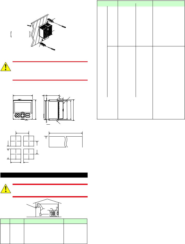
n Mounting the Instrument Main Unit
Provide an instrumented panel steel sheet of 1 to 10 mm thickness.
After opening the mounting hole on the panel, follow the procedures below to install the controller:
1)Insert the controller into the opening from the front of the panel so that the terminal board on the rear is at the far side.
2)Set the brackets in place on the top and bottom of the controller as shown in the figure below, then tighten the screws of the brackets. Take care not to overtighten them.
Direction to insert the
controller
Insert the controller into the opening at the front of the panel.
Panel |
Bracket |
|
(top mounting hardware) |
|
Terminal board |
|
Insert a screwdriver into the |
|
brackets to tighten the screws. |
|
Appropriate |
Bracket |
tightening torque: |
(bottom mounting hardware) |
0.25 N•m |
•Tighten the screws with appropriate tightening torque within 0.25 N•m. Otherwise it may cause the case deformation or the bracket
damage.
CAUTION • Make sure that foreign materials do not enter the inside of the instrument through the case’s slit holes.
n External Dimensions and Panel Cutout Dimensions
UT35A-L |
11 |
|
Unit: mm (approx. inch) |
|||
96 (3.78) |
(0.43) |
65 (2.56) |
Bracket |
|
Terminal cover |
|
|
|
|
|
|||
|
|
|
20 |
(0.79) |
|
|
96 (3.78) |
|
|
|
91.6 (3.61) |
94.6 (3.72) |
105.2 (4.14) |
|
|
|
Bracket |
|
|
|
• General mounting
117 (4.61) min.
(53) (2.09)
92+00.8
(3.62+0.030 )
92+0.80 (25)
(3.62+0.030 ) (0.98)

 1 to 10 mm (0.04 to 0.39 inch) (panel thickness)
• Side-by-side close mounting
[(N-1)×96+92]+0.80 ([(N-1)×3.78+3.62] +0.030 )
92+0.80
(3.62+0.030 )
145 (5.71) 
 min. “N” stands for the number of controllers to be
installed.
However, the measured value applies if N≥5.
Normal tolerance:
±(value of JIS B 0401-1998 tolerance class IT18)/2
4.Hardware Specifications
This instrument is for Measurement Category I (CAT.I). Do not use it for measurements in locations falling under Measurement Catego-
WARNING ries II, III, and IV.
|
|
Internal Wiring |
II |
|
|
Entrance IV |
III |
T |
|
|
I |
|
|
|
|
Cable |
Outlet |
|
|
|
|
|
|
|
Category |
Measurement |
Description |
|
Remarks |
|
category |
|
|
|
I |
CAT.I |
For measurements performed on circuits not |
- |
|
directly connected to MAINS. |
||||
|
|
|
||
II |
CAT.II |
For measurements performed on circuits di- |
Appliances, portable equip- |
|
rectly connected to the low-voltage installation. |
ment, etc. |
|||
|
|
|||
III |
CAT.III |
For measurements performed in the building |
Distribution board, circuit |
|
installation. |
breaker, etc. |
|||
|
|
|||
IV |
CAT.IV |
For measurements performed at the source of |
Overhead wire, cable |
|
the low-voltage installation. |
systems, etc. |
|||
|
|
n Input Specifications
●Universal Input (Equipped as standard)
•Number of inputs: 1
•Input type, instrument range, and measurement accuracy: See the table below,
Input Type |
|
Instrument Range |
Accuracy |
|||
ºC |
ºF |
|||||
|
|
|
||||
|
|
-270.0 to 1370.0ºC |
-450.0 to 2500.0ºF |
±0.1% of instrument range ±1 digit for |
||
|
K |
-270.0 to |
1000.0ºC |
-450.0 to 2300.0ºF |
0°C or more |
|
|
|
|
|
|
±0.2% of instrument range ±1 digit for |
|
|
|
-200.0 to |
500.0ºC |
-200.0 to 1000.0ºF |
||
|
|
less than 0°C |
||||
|
J |
-200.0 to 1200.0ºC |
-300.0 to 2300.0ºF |
±2% of instrument range ±1 digit for |
||
|
|
-270.0 to 400.0ºC |
-450.0 to 750.0ºF |
less than -200.0°C of thermocouple K |
||
|
T |
|
|
|
±1% of instrument range ±1 digit for |
|
|
0.0 to 400.0ºC |
-200.0 to 750.0ºF |
||||
|
|
less than -200.0°C of thermocouple T |
||||
|
|
|
|
|
±0.15% of instrument range ±1 digit |
|
|
B |
0.0 to 1800.0ºC |
32 to 3300ºF |
for 400°C or more |
||
|
±5% of instrument range ±1 digit for |
|||||
|
|
|
|
|
||
|
|
|
|
|
less than 400°C |
|
|
S |
0.0 to 1700.0ºC |
32 to 3100ºF |
±0.15% of instrument range ±1 digit |
||
|
R |
0.0 to 1700.0ºC |
32 to 3100ºF |
|||
|
|
|||||
|
|
|
|
|
±0.1% of instrument range ±1 digit |
|
Thermo- |
N |
-200.0 to 1300.0ºC |
-300.0 to 2400.0ºF |
±0.25% of instrument range ±1 digit |
||
couple |
|
|
|
|
for less than 0°C |
|
E-270.0 to 1000.0ºC -450.0 to 1800.0ºF ±0.1% of instrument range ±1 digit for
|
L |
-200.0 to 900.0ºC |
-300.0 to 1600.0ºF |
0°C or more |
|
|
|
|
±0.2% of instrument range ±1 digit for |
|
|
-200.0 to 400.0ºC |
-300.0 to 750.0ºF |
|
|
|
less than 0°C |
||
|
U |
0.0 to 400.0ºC |
-200.0 to 1000.0ºF |
±1.5% of instrument range ±1 digit for |
|
|
|||
|
|
|
|
less than -200.0°C of thermocouple E. |
|
W |
0.0 to 2300.0ºC |
32 to 4200ºF |
±0.2% of instrument range ±1 digit |
|
(Note 2) |
|||
|
|
|
|
|
|
Platinel 2 |
0.0 to 1390.0ºC |
32.0 to 2500.0ºF |
±0.1% of instrument range ±1 digit |
|
|
|
|
±0.5% of instrument range ±1 digit for |
|
PR20-40 |
0.0 to 1900.0ºC |
32 to 3400ºF |
800°C or more |
|
Accuracy is not guaranteed for less |
|||
|
|
|
|
|
|
|
|
|
than 800°C. |
|
W97Re3- |
0.0 to 2000.0ºC |
32 to 3600ºF |
±0.2% of instrument range ±1 digit |
|
W75Re25 |
|||
|
|
|
|
|
|
|
-200.0 to 500.0ºC |
-300.0 to 1000.0ºF |
±0.1% of instrument range ±1 digit |
|
JPt100 |
(Note 1) |
||
RTD |
|
-150.00 to 150.00ºC |
-200.0 to 300.0ºF |
±0.1% of instrument range ±1 digit |
|
-200.0 to 850.0ºC |
-300.0 to 1560.0ºF |
±0.1% of instrument range ±1 digit |
|
|
|
|||
|
Pt100 |
-200.0 to 500.0ºC |
-300.0 to 1000.0ºF |
(Note 1) |
|
|
-150.00 to 150.00ºC |
-200.0 to 300.0ºF |
±0.1% of instrument range ±1 digit |
|
|
0.400 to 2.000 V |
|
|
Standard signal |
1.000 to 5.000 V |
|
||
|
|
4.00 to 20.00 mA |
|
|
|
|
0.000 to 2.000 V |
±0.1% of instrument range ±1 digit |
|
|
|
0.00 to 10.00 V |
||
|
|
|
||
DC voltage/current |
0.00 to 20.00 mA |
|
||
|
|
-10.00 to 20.00 mV |
|
|
|
|
0.0 to 100.0 mV |
|
|
The accuracy is that in the standard operating conditions: 23±2°C, 55±10%RH, and power frequency at 50/60 Hz.
Note 1: ±0.3°C ±1 digit in the range between 0 and 100°C, ±0.5°C ±1 digit in the range between -100 and 200°C.
Note 2: W: W-5% Re/W-26% Re(Hoskins Mfg.Co.). ASTM E988
•Input sampling (control) period: 200 ms
•Burnout detection:
Functions at TC, RTD, and standard signal. Upscale, downscale, and off can be specified.
For standard signal, burnout is determined to have occurred if it is 0.1 V or 0.4 mA or less.
•Input bias current: 0.05 µA (for TC or RTD)
•Measured current (RTD): About 0.16 mA
•Input resistance:
TC or mV input: 1 MΩ or more V input: About 1 MΩ
mA input: About 250 Ω
•Allowable signal source resistance: TC or mV input: 250 Ω or less
Effects of signal source resistance: 0.1 µV/Ω or less DC voltage input: 2 kΩ or less
Effects of signal source resistance: About 0.01%/100 Ω
•Allowable wiring resistance:
RTD input: Max. 150 Ω/wire (The conductor resistance between the three wires shall be equal.)
Wiring resistance effect: ±0.1ºC/10 Ω
• Allowable input voltage/current:
TC, mV, mA and RTD input: ±10 V DC V input: ±20 V DC
mA input: ±40 mA
• Noise rejection ratio:
Normal mode: 40 dB or more (at 50/60 Hz) Common mode: 120 dB or more (at 50/60 Hz)
For 100-240 V AC, the power frequency can be set manually. Automatic detection is also available.
For 24 V AC/DC, the power frequency can be set manually.
•Reference junction compensation error: ±1.0ºC (15 to 35ºC)
±1.5ºC (-10 to 15ºC and 35 to 50ºC)
•Applicable standards: JIS/IEC/DIN (ITS-90) for TC and RTD
n Step Response Time Specifications
Within 1 s (63% of analog output response time when a step change of 10 to 90% of input span is applied)
n Relay Contact Output Specifications
• Contact type and number of outputs:
Limit control output: contact point 1c; 1 point
Alarm output: contact point 1a; 3 points (common is independent)
• Contact rating:
Contact point 1c (limit control output): 250 V AC, 3 A or 30 V DC, 3A (resistance load) Contact point 1a (alarm output): 240 V AC, 1A or 30 V DC, 1 A (resistance load)
•Use: Alarm output, FAIL output, etc.
•Time resolution of limit control output: 10 ms or 0.1% of output, whichever is larger
Note: This cannot be used for a small load of 10 mA or less.
n Retransmission Output Specifications
•Number of outputs: Retransmission output; 1
•Current output: 4 to 20 mA DC or 0 to 20 mA DC/ load resistance of 600 Ω or less
•Current output accuracy: ±0.1% of span (±5% of span for 1 mA or less)
The accuracy is that in the standard operating conditions: 23±2°C, 55±10%RH, and power frequency at 50/60 Hz.
n Contact Input Specifications
•Number of inputs: 2 points
•Input type: No-voltage contact input or transistor contact input
•Input contact rating: 12 V DC, 10 mA or more
Use a contact with a minimum on-current of 1 mA or more.
• ON/OFF detection: No-voltage contact input:
Contact resistance of 1 kΩ or less is determined as “ON” and contact resistance of 50 kΩ or more as “OFF.”
Transistor contact input:
Input voltage of 2 V or less is determined as “ON” and leakage current must not exceed 100 µA when “OFF.”
•Minimum status detection hold time: Control period +50 ms
•Use: Confirmation operation, etc.
■ Safety and EMC Standards
•Safety: Compliant with IEC/EN61010-1 (CE), approved by CAN/CSA C22.2 No.61010-1 (CSA), approved by UL61010-1. Certified for FM-3810 and FM-3545.
Installation category: CAT. II Pollution degree: 2 Measurement category: I (CAT. I)
Rated measurement input voltage: Max. 10 V DC
Rated transient overvoltage: 1500 V (Note)
Note: This is a reference safety standard value for Measurement Category I of IEC/EN/CSA/ UL61010-1. This value is not necessarily a guarantee of instrument performance.
•EMC Conformity standards: CE marking
EN61326-1 Class A, Table 2 (For use in industrial locations) EN61326-2-3
EN 55011 Class A, Group1 EN 61000-3-2 Class A EN 61000-3-3
C-tick mark
EN 55011 Class A, Group1
The instrument continues to operate at a measurement accuracy of within ±20% of the range during testing.
■ Construction, Installation, and Wiring
•Degree of protection provided by Enclosure: IP66 (for front panel) (Not available for side-by-side close mounting.)
•Material: Polycarbonate (Flame retardancy: UL94V-0)
•Case color: White (Light gray) or Black (Light charcoal gray)
•Weight: 0.5 kg or less
•External dimensions (mm): 96 (W) × 96 (H) × 65 (depth from the panel face) (Depth except the projection on the rear panel)
•Installation: Direct panel mounting; mounting bracket, one each for upper and lower mounting
•Panel cutout dimensions (mm): 92+0.8/0 (W) × 92+0.8/0 (H)
•Mounting attitude: Up to 30 degrees above the horizontal. No downward titling allowed.
•Wiring: M3 screw terminal with square washer (for signal wiring and power wiring)
■ Power Supply Specifications and Isolation
• Power supply:
Rated voltage: 100-240 V AC (+10%/-15%), 50/60 Hz 24 V AC/DC (+10%/-15%) (for /DC option)
•Power consumption: 18 VA (DC:9 VA, AC: 14 VA if /DC option is specified)
•Data backup: Nonvolatile memory
•Power holdup time: 20 ms (for 100 V AC drive)
•Withstanding voltage
Between primary terminals and secondary terminals: 2300 V AC for 1 minute Between primary terminals: 1500 V AC for 1 minute
Between secondary terminals: 500 V AC for 1 minute
(Primary terminals: Power* and relay output terminals; Secondary terminals: Analog I/O signal terminals, contact input terminals, communication terminals and functional grounding terminals.)
*: Power terminals for 24V AC/DC models are the secondary terminals.
•Insulation resistance: Between power supply terminals and a grounding terminal 20 MΩ or more at 500 V DC
•Isolation specifications
PV (universal) input terminals |
|
|
|
|
|
|
|
Retransmission (analog) output terminals |
|
|
|
|
|
|
|
Control relay (contact point c) output terminals |
|
|
|
|
|
|
|
Alarm-1 relay (contact point a) output terminals |
Internal |
Power |
|
|
|||
Alarm-2 relay (contact point a) output terminals |
|||
circuits |
supply |
||
Alarm-3 relay (contact point a) output terminals |
|
|
|
Contact input terminals |
|
|
|
RS-485 communication terminals |
|
|
|
Ethernet communication terminal |
|
|
|
|
|
|
The circuits divided by lines are insulated mutually.
■ Environmental Conditions
Normal Operating Conditions:
•Ambient temperature: -10 to 50ºC (-10 to 40ºC for side-by-side close mounting)
•Ambient humidity: 20 to 90% RH (no condensation allowed)
•Magnetic field: 400 A/m or less
•Continuous vibration at 5 to 9 Hz: Half amplitude of 1.5 mm or less, 1oct/min for 90 minutes each in the three axis directions
Continuous vibration at 9 to 150 Hz: 4.9 m/s2 or less, 1oct/min for 90 minutes each in the three axis directions
•Short-period vibration: 14.7 m/s2, 15 seconds or less
•Shock: 98 m/s2 or less, 11 ms
•Altitude: 2000 m or less above sea level
•Warm-up time: 30 minutes or more after the power is turned on
•Startup time: Within 10 seconds
*: The LCD (a liquid crystal display) is used for a display portion of this product. The LCD has a characteristic that the display action becomes late at the low temperature. However, the control function is not affected.
Transportation and Storage Conditions:
•Temperature: -25 to 70ºC
•Temperature change rate: 20ºC/h or less
•Humidity: 5 to 95% RH (no condensation allowed)
Effects of Operating Conditions
• Effect of ambient temperature:
Voltage or TC input: ±1 µV/ºC or ±0.01% of F.S./ºC, whichever is larger Current input: ±0.01% of F.S./ºC
RTD input: ±0.05ºC/ºC (ambient temperature) or less Analog output: ±0.02% of F.S./ºC or less
•Effect of power supply voltage fluctuation Analog input: ±0.05% of F.S. or less Analog output: ±0.05% of F.S. or less (Each within rated voltage range)
IM 05P04D41-11EN page 2/10

5.How to Connect Wires
•Wiring work must be carried out by a person with basic electrical knowledge and practical experience.
WARNING • Be sure to turn OFF the power supply to the controller before wiring to avoid an electric shock. Use a tester or similar device
to ensure that no power is being supplied to a cable to be connected.
•As a safety measure, always install a circuit breaker (an IEC 60947-compatible product, 5 A, 100 V or 220 V AC) in an easily accessible location near the instrument. Moreover, provide indication that the switch is a device for turning off the power to the instrument.
•Install the power cable keeping a distance of more than 1 cm from other signal wires.
•The power cable is required to meet the IEC standards concerned or the requirements of the area in which the instrument is being installed.
•Wiring should be installed to conform to NEC (National Electrical Code: ANSI/NFPA-70) or the wiring construction standards in countries or regions where wiring will be installed.
•For control relay output, alarm relay output, and power terminal connections, use heat-resistant cables.
•Since the insulation provided to each relay output terminal is Functional insulation, provide Reinforced insulation to the external of the device as necessary. (Refer to the drawing below.)
This product |
Asafety |
voltage circuit |
Functional |
insulation |
Asafety |
voltage circuit |
This product |
|
|
|
Asafety |
Asafety |
|
voltage circuit |
voltage circuit |
Functional |
Reinforced insulation |
|
insulation |
||
|
Ahazardous |
Ahazardous |
|
voltage circuit |
voltage circuit |
|
Reinforced insulation |
|
This product |
|
|
|
Ahazardous |
Ahazardous |
|
voltage circuit |
voltage circuit |
Functional |
Reinforced insulation |
|
insulation |
||
|
Ahazardous |
Ahazardous |
|
voltage circuit |
voltage circuit |
|
Reinforced insulation |
|
•When connecting two or more crimp-on terminal lugs to the single terminal block, bend the crimp-on terminal lugs before
tightening the screw.
CAUTION • Note that the wiring of two or more crimp-on terminal lugs to the single high-voltage terminal of the power supply and relay, etc. does not comply with the safety standard.
•Provide electricity from a single-phase power supply. If the power is noisy, install an isolation transformer on the primary
 side, and use a line filter on the secondary side. When measures CAUTION against noise are taken, do not install the primary and secondary
power cables close to each other.
•If there is a risk of external lightning surges, use a lightning arrester etc.
•For TC input, use shielded compensating lead wires for wiring. For RTD input, use shielded wires that have low conductor resistance and cause no significant differences in resistance between the three wires.
•Since the limit control output relay has a life span (resistance load of 100,000 times), use the auxiliary relay to perform ON/OFF control.
•The use of inductance (L) loads such as auxiliary relays, motors and solenoid valves causes malfunction or relay failure; always insert a CR filter for use with alternating current or a diode for use with direct current, as a spark-removal surge suppression circuit, into the line in parallel with the load.
•After completing the wiring, the terminal cover is recommended to use for the instrument.
● Recommended Crimp-on Terminal Lugs
|
(ød) |
|
(A) |
5.5 |
3.3 |
|
(F) |
|
Recommended tightening torque: 0.6 N·m
Applicable wire size: Power supply wiring 1.25 mm2 or more
Applicable terminal lug |
Applicable wire size mm2 (AWG#) |
(φ d) |
(A) |
(F) |
M3 |
0.25 to 1.65 (22 to 16) |
3.3 |
5.5 |
4.2 |
● Cable Specifications and Recommended Cables
Purpose |
Name and Manufacturer |
Power supply, relay contact outputs |
600 V Grade heat-resistant PVC insulated wires, JIS C |
|
3317(HIV), 0.9 to 2.0 mm2 |
Thermocouple |
Shielded compensating lead wires, JIS C 1610 |
RTD |
Shielded wires (three/four conductors), UL2482 (Hitachi Cable) |
Other signals (other than contact input/output) |
Shielded wires |
Other signals (contact input/output) |
Unshielded wires |
RS-485 communication |
Shielded wires |
Ethernet communication |
100 BASE-TX (CAT-5)/10 BASE-T |
DC Relay Wiring
UT35A-L
|
Relay |
External DC power supply |
|
|
|
|
|
|
|
|
R |
|
|
|
Diode |
UT’s contact |
|
Relay |
(Mount it directly |
|
to the relay coil |
||
(Use one with a relay coil rating |
terminal (socket).) |
|
less than the UT’s contact rating.) |
||
|
AC Relay Wiring
UT35A-L |
External AC power supply |
|
|
|
|
|
|
R |
UT’s contact |
Relay |
CR filter |
(Use one with a relay coil |
(Mount it directly |
|
rating less than the UT’s |
to the relay coil |
|
|
contact rating.) |
terminal (socket).) |
6.Terminal Wiring Diagrams
•Do not use an unassigned terminal as the relay terminal.
Do not use a 100-240 V AC power supply for the 24 V AC/DC
model; otherwise, the instrument will malfunction.
CAUTION
■ UT35A-L |
|
|
|
|
|
|
|
|
|
|
|
|
|
|
|
|
|
|
|
|
|
||
Limit control output |
OUT |
|
PV input |
PV as(Equippedstandard) |
Retransmission output |
RET (Equipped as standard) |
|
||||||||||||||||
Relay contact output |
|
|
(Equipped as standard) |
Factory default: PV input |
TC input |
RTD input |
|
Retransmission output |
|
|
|
|
|
|
|
||||||||
|
|
|
|
type is undefined. |
|
|
|
|
|
|
|
|
|||||||||||
|
101 |
|
|
|
|
|
|
|
|
A 201 |
|
Default: PV |
|
|
|
|
|
|
|
|
|
||
NC |
|
|
|
|
|
|
|
|
|
|
|
|
|
|
|
|
|
|
|
||||
|
|
|
|
|
|
+ 202 |
|
|
retransmission |
+ |
207 |
|
|
|
|
|
|
|
|||||
|
|
|
|
|
|
|
|
|
|
|
|
|
|
|
|
|
|
|
|||||
NO |
102 |
|
|
|
|
|
|
|
|
|
b |
202 |
|
4-20 mADC or |
|
|
|
|
|
|
|
|
|
|
103 |
|
|
|
|
|
|
- |
203 |
|
B 203 |
|
0-20 mADC |
- |
208 |
|
|
|
|
|
|
|
|
COM |
|
|
|
|
|
|
|
|
|
|
Loadresistance600Ωorless |
|
|
|
|
|
|
|
|||||
|
|
|
|
|
|
|
|
|
|
|
|
|
|
Default: 4-20 mADC |
|
|
|
|
|
|
|
|
|
Contact rating: 250 V AC, 3 A |
|
|
|
|
Current (mA) input |
Voltage (mV, V) input |
|
|
|
|
|
|
|
|
|
|
|||||||
|
30 V DC, 3 A (resistance load) |
|
|
|
|
|
|
|
Contact input |
DI (Equipped as standard) |
|
|
|||||||||||
|
|
|
|
|
|
|
|
- |
203 |
|
+ 202 |
|
|
|
|||||||||
|
|
|
|
|
|
|
|
|
|
|
|
|
|
External contact input |
|
|
|||||||
|
|
|
|
|
|
|
|
|
|
|
|
|
|
|
|
|
|
|
|
||||
|
|
|
|
|
|
|
|
+ 204 |
|
- |
203 |
|
|
|
|
|
No-voltage |
UT |
Transistor |
UT |
+5V |
||
|
|
|
|
|
|
|
|
|
|
|
|
|
|
|
contact |
|
|||||||
|
|
|
|
|
|
|
|
|
|
|
|
|
|
|
|
|
|
|
|
|
contact |
DI2 |
|
|
|
|
|
|
|
|
|
|
|
|
|
|
|
Factory default: No function |
|
210 DI2 |
210 |
+5V |
|||||
Contact output |
ALM |
(Equipped |
|
101 |
501 |
401 |
301 |
|
201 |
RESET when DI=ON |
|
|
211 DI1 |
211 DI1 |
|||||||||
as standard) |
|
|
(However, setup parameter CNF=DI) |
|
|
|
|
COM |
|
||||||||||||||
|
External contact output (relay) |
|
|
-112 |
-512 |
-412 |
-306 |
-212 |
|
|
|
|
|
212 COM |
212 |
|
|||||||
|
|
|
Common |
|
|
|
|
||||||||||||||||
|
|
|
101 |
|
401 |
|
|
201 |
|
|
|
|
|||||||||||
Alarm-3 output |
|
104 |
|
|
UT |
|
|
|
|
|
|
|
|
Contact rating: 12 V DC, 10 mA or more |
|
|
|||||||
(PV high limit) |
AL3 |
|
|
|
|
102 |
|
|
|
|
202 |
|
|
|
|
|
|
||||||
|
|
|
|
|
|
|
|
Function can be assigned to the terminals with no function. |
|
|
|||||||||||||
|
Common |
|
105 |
|
|
|
|
103 |
|
|
|
|
203 |
|
|
|
|
|
|
|
|
|
|
Alarm-2 output |
|
|
|
|
|
|
|
|
|
|
|
|
|
|
|
|
|
|
|
|
|||
|
106 |
|
|
|
|
104 |
|
|
|
|
204 |
Ethernet communication (with gateway function) |
|
|
|||||||||
( PV low limit) |
AL2 |
|
|
|
|
|
|
|
|
|
|
||||||||||||
107 |
|
|
|
Wiring direction |
|
|
|
|
|
|
|||||||||||||
|
Common |
|
|
|
|
|
105 |
|
|
|
|
205 |
Do not use. |
|
|
|
|
ETHR |
|
|
|
||
Alarm-1 output |
|
|
|
|
|
|
106 |
|
|
|
|
206 |
10BASE-T/100BASE-TX |
|
|
|
|
||||||
|
108 |
|
|
|
|
|
|
|
|
RJ45 connector |
|
|
|
(Suffix code: Type 3=2) |
|
|
|||||||
(PV high limit) |
AL1 |
|
|
|
|
|
|
|
|
|
|
|
|
|
|||||||||
109 |
|
|
|
|
107 |
|
407 |
|
|
207 |
|
|
|
|
|
|
|
|
|
|
|||
|
Common |
|
|
|
|
|
|
|
|
|
|
|
|
|
|
|
|
|
|
||||
|
|
|
|
|
|
108 |
|
408 |
|
|
208 |
Upper side LED (baud rate) |
|
|
|
|
|
|
|||||
Relay contact rating: 240 V AC, 1 A |
|
|
|
|
|
|
|
|
|
|
|
|
|||||||||||
|
|
|
109 |
|
409 |
|
|
|
Color |
Amber |
|
|
|
|
|
|
|
||||||
|
|
30 V DC, 1 A (resistance load) |
|
|
|
|
|
Lit |
100M bps |
|
|
|
|
|
|
|
|||||||
|
|
|
|
|
|
|
|
110 |
|
410 |
|
|
210 |
|
|
|
RS-485 |
|
|
||||
|
|
|
|
|
|
|
|
|
|
|
Unlit |
10M bps |
|
|
|
|
|
||||||
|
|
|
|
|
|
|
|
111 |
|
411 |
|
|
211 |
Lower side LED (link activity) |
|
|
RSB(+) 407 |
|
|
||||
|
|
|
|
|
|
|
|
|
|
|
Color |
Green |
|
|
|
|
|
||||||
|
|
|
|
|
|
|
|
|
|
|
|
|
|
|
|
|
|
|
|||||
|
|
|
|
|
|
|
|
112 |
|
412 |
|
|
212 |
|
|
|
|
|
|
|
|||
|
Power supply |
|
|
|
|
|
|
|
Lit |
Linked |
|
|
|
RSA(-) 408 |
|
|
|||||||
|
|
|
|
|
|
|
|
|
|
|
|
|
|
|
|
||||||||
|
|
|
|
|
|
|
|
|
|
|
Blink |
Active |
|
|
|
|
409 |
|
|
||||
100-240VACpowersupply |
24 VAC/DC power supply |
|
|
|
|
|
|
|
Unlit |
Link failure |
|
|
|
SG |
|
|
|||||||
|
N |
110 |
|
N |
- |
110 |
|
|
|
401-412 |
E3-terminal area |
|
|
|
|
|
|
|
|
|
|||
|
L |
111 |
|
L |
+ |
111 |
|
|
|
|
|
|
|
RS-485communication |
RS485 |
|
|
|
|
||||
|
|
112 |
|
|
|
112 |
|
|
|
|
|
|
|
RS-485 |
|
(Suffix code: Type 3=1) |
|
|
|
||||
|
|
|
|
|
|
|
|
|
|
|
|
|
|
|
|
|
|
|
|
|
|
||
Allowable range: |
|
(24 V AC/DC power supply: Optional suffix code /DC) |
|
|
|
|
|
|
SDB(+) 407 |
|
|
|
|
|
|
|
|||||||
|
|
|
|
|
|
|
|
|
|
|
|
|
|
|
|
|
|||||||
100-240 V AC |
|
|
|
|
|
|
|
|
|
|
|
SDA(-) 408 |
|
|
|
|
|
|
|
||||
(+10%, -15%) |
|
|
|
|
|
|
|
|
|
|
|
|
|
|
|
|
|
|
|||||
(free voltage) |
|
|
|
|
|
|
|
|
|
|
|
|
|
|
|
|
|
|
|
|
|
|
|
50/60 Hz shared |
|
|
|
|
|
|
|
|
|
|
|
SG |
409 |
|
|
|
|
|
|
|
|||
|
|
|
|
|
|
|
|
|
|
|
|
|
|
RDB(+) 410 |
|
|
|
|
|
|
|
||
|
|
|
|
|
|
|
|
|
|
|
|
|
|
RDA(-) |
411 |
|
|
|
|
|
|
|
|
IM 05P04D41-11EN page 3/10
 Loading...