


ISC202
Table of contents
 Loading...
User’s
Manual
Model ISC202G [Style: S2], ISC202S [Style: S3]
2-wire Inductive Conductivity
Transmitter
IM 12D06A03-01E
7th Edition
IM 12D06A03-01E

IM 12D06A03-01E
IM 12D06A03-01E
7th Edition: Oct. 2009(YK)
All Rights Reserved, Copyright © 2001, Yokogawa Electric Corporation
TABLE OF CONTENTS
PREFACE
1. Introduction And General Description ............................................................. 1-1
1-1. Instrument check ............................................................................................ 1-1
1-2. Application ...................................................................................................... 1-3
2. GENERAL SPECIFICATIONS ............................................................................. 2-1
2-1. Specifications .................................................................................................. 2-1
2-2. Model and suffix codes ................................................................................... 2-6
2-3. Control Drawing ISC202S mA HART
®
Specification (IECEx). ....................... 2-7
2-4. Control Drawing ISC202S mA HART
®
Specification (ATEX) ......................... 2-8
2-5. Control Drawing ISC202S mA HART
®
Specification
(FM Intrinsically safe design) ........................................................................... 2-9
2-6. Control Drawing ISC202S mA HART
®
Specification
(FM Non-incendive design) ............................................................................ 2-10
2-7. Control Drawing of ISC202S mA HART
®
Specification (CSA) ......................2-11
2-8. Control Drawing of ISC202S FF/PB Specification (IECEx) .......................... 2-12
2-9. Control Drawing of ISC202S FF/PB Specification (ATEX) ........................... 2-13
2-10. Control Drawing of ISC202S FF/PB Specification
(FM Intrinsically safe Entity) ........................................................................... 2-14
2-11. Control Drawing of ISC202S FF/PB Specification
(FM Intrinsically safe FISCO) ......................................................................... 2-16
2-12. Control Drawing of ISC202S FF/PB Specification
(FM Non-incendive Entity) ............................................................................. 2-18
2-13. Control Drawing of ISC202S FF/PB Specification
(FM Non-incendive FNICO) ........................................................................... 2-19
2-14. Control Drawing of ISC202S FF/PB Specification (CSA) ........................... 2-20
3. Installation And Wiring....................................................................................... 3-1
3-1. Installation and dimensions ............................................................................ 3-1
3-1-1. Installation site .................................................................................................................3-1
3-1-2. Mounting methods ...........................................................................................................3-1
3-2. Preparation ..................................................................................................... 3-2
3-2-1. Cables, terminals and glands ..........................................................................................3-2
3-3. Wiring of sensors ............................................................................................ 3-3
3-3-1. General precautions ........................................................................................................3-3
3-3-2. Additional precautions for installations in hazardous areas ...........................................3-3
3-3-3. Installation in: Hazardous Area-Non-Incendive ..............................................................3-3
3-4 Wiring of the power supply .............................................................................. 3-4
3-4-1 General precautions .........................................................................................................3-4
3-4-2. Connection of the power supply ......................................................................................3-4
3-4-3. Switching the instrument on ............................................................................................3-4
3-5. Sensor wiring .................................................................................................. 3-4
3-6. Other sensor systems ..................................................................................... 3-5
3-6-1. Sensor cable connections using junction box (BA10) and extension cable (WF10) .......3-5
4. Operation; Display Functions And Setting ...................................................... 4-1
4-1. Operator interface ........................................................................................... 4-1
4-2. Explanation of operating keys ......................................................................... 4-2
4-3. Setting passcodes .......................................................................................... 4-3
4-3-1. Passcode protection ........................................................................................................4-3
4-4. Display examples ............................................................................................ 4-3
4-5. Display functions ............................................................................................. 4-4

IM 12D06A03-01E
5. Parameter setting ............................................................................................... 5-1
5-1. Maintenance mode ......................................................................................... 5-1
5-1-1. Introduction ......................................................................................................................5-1
5-1-2. Manual calibration to determine the cell constant (C.C.) ................................................5-2
5-1-3. Second Line display. Referring to the first compensated conductivity. ...........................5-3
5-1-4. Second Line display. Referring to the second compensated conductivity. .....................5-4
5-1-5. Manual activation of HOLD ............................................................................................5-5
5-2. Commissioning mode ..................................................................................... 5-6
5-2-1. Linear output (Range) ......................................................................................................5-7
5-2-2. HOLD ..............................................................................................................................5-8
5-2-3. Temperature compensation .............................................................................................5-9
5-2-4. Temperature compensation for first conductivity value .................................................5-11
5-2-5. Temperature Compensation for second conductivity value ..........................................5-12
5-3.Service Codes ............................................................................................... 5-13
5-3-1. Parameter specific functions .........................................................................................5-13
5-3-2. Temperature measuring functions .................................................................................5-13
5-3-3. Temperature compensation functions ...........................................................................5-14
5-3-4. mA output functions .......................................................................................................5-16
5-3-5. User interface ................................................................................................................5-18
5-3-6. Communication setup ....................................................................................................5-19
5-3-7. General .........................................................................................................................5-19
6. Calibration ....................................................................................................... 6-1
6-1 When is calibration necessary? ....................................................................... 6-1
6-2. Calibration procedure ..................................................................................... 6-2
7. Maintenance ....................................................................................................... 7-1
7-1. Periodic maintenance for the EXA 202 transmitter ......................................... 7-1
7-2. Periodic maintenance of the sensor ............................................................... 7-1
8. Troubleshooting ................................................................................................. 8-1
8-1. Introduction ..................................................................................................... 8-1
8-2. Self diagnostics of the conductivity sensor ..................................................... 8-1
8-3. Self diagnostics of the temperature sensor .................................................... 8-1
8-4. Self diagnostics of the electronics .................................................................. 8-1
8-5. Checking during operation .............................................................................. 8-1
9. Error messages and explanation ...................................................................... 9-1
10. Spare Parts ..................................................................................................... 10-1
11. Appendix 1 ....................................................................................................... 1-1
11-1. User setting for non-linear output table (code 31, 35) ................................... 1-1
11-2. User entered matrix data (code 23 to 28) ..................................................... 1-1
11-3. Matrix data table (user selectable in code 22) .............................................. 1-2
11-4. Configuration Checklist For ISC202 ............................................................. 1-3
11-5. Coded service settings (default) ................................................................... 1-3
11-6. Device Description (DD) menu structure ...................................................... 1-4
IM 12D06A03-01E
In this manual a
mA
sign appears if it concerns the ISC202G-A and ISC202S-A, -N, -K.
12. APPENDIX 2 ...................................................................................................... 2-1
12-1. Preface ....................................................................................................... 2-1
12-2. Wiring diagrams ............................................................................................ 2-1
12-3. Peripheral products ....................................................................................... 2-2
12-3-1. PH201G*B Dedicated Distributor .................................................................................2-2
12-3-2. BA20 Junction Terminal Box ........................................................................................2-3
12-3-3. WF10J Extension Cable ...............................................................................................2-4
12-4. Quick reference for parameter setting ......................................................... 2-5
12-4-1. Settings Performed in Maintenance Mode ................................................ 2-6
12-4-1-1 Calibration with solution of known conductivity ..................................... 2-6
12-4-1-2 Selecting Items for Display ......................................................................................2-6
12-4-2. Commissioning Mode Settings ............................................................... 2-7
12-4-2-1 Output Range Setting ...............................................................................................2-7
12-4-2-2 Setting Hold Functions ..............................................................................................2-7
12-4-2-3 Temperature Compensation ....................................................................................2-8
12-4-2-4 Correcting Zero Offset Error by Calibration in Air (Air Set) .......................................2-8
12-4-3. Actual Setting Examples ........................................................................ 2-9
12-4-3-1 Setting Output in terms of Concentration ..............................................................2-10
12-4-3-2 Key Operation Procedure Examples ......................................................................2-15
12-5. Installation factor adjustment ..................................................................... 2-19
13. Appendix 3 QUALITY INSPECTION ................................................................. 3-1
13-1. ISC202G 2-Wire Inductive Conductivity Transmitter .................................... 3-1
13-2. ISC202S 2-Wire Inductive Conductivity Transmitter ..................................... 3-6
13-3. ISC202G, ISC202S 2-Wire Inductive Conductivity Transmitter
(Fieldbus Communication) ..............................................................................3-11
13-4. ISC202G, ISC202S 2-Wire Inductive Conductivity Transmitter
(Profibus Communication) ............................................................................. 3-15
Customer Maintenance Parts List for ISC202G (Style : S2)
.......CMPL12D06A03-02E
Customer Maintenance Parts List for ISC202S (Style : S3) ...CMPL12D06A03-23E
Revision Record ..........................................................................................................i
IM 12D06A03-01E
PREFACE
Electric discharge
The EXA analyzer contains devices that can be
damaged by electrostatic discharge. When servicing
this equipment, please observe proper procedures
to prevent such damage. Replacement components
should be shipped in conductive packaging. Repair
work should be done at grounded workstations using
grounded soldering irons and wrist straps to avoid
electrostatic discharge.
Installation and wiring
The EXA analyzer should only be used with equip-
ment that meets the relevant international and
regional standards. Yokogawa accepts no responsi-
bility for the misuse of this unit.
The instrument is packed carefully with shock
absorbing materials, nevertheless, the instrument
may be damaged or broken if subjected to strong
shock, such as if the instrument is dropped. Handle
with care.
Although the instrument has a weatherproof
construction, the transmitter can be harmed if it
becomes submerged in water or becomes exces-
sively wet.
Do not use an abrasive material or solvent when
cleaning the instrument.
Do not modify the ISC202 transmitter.
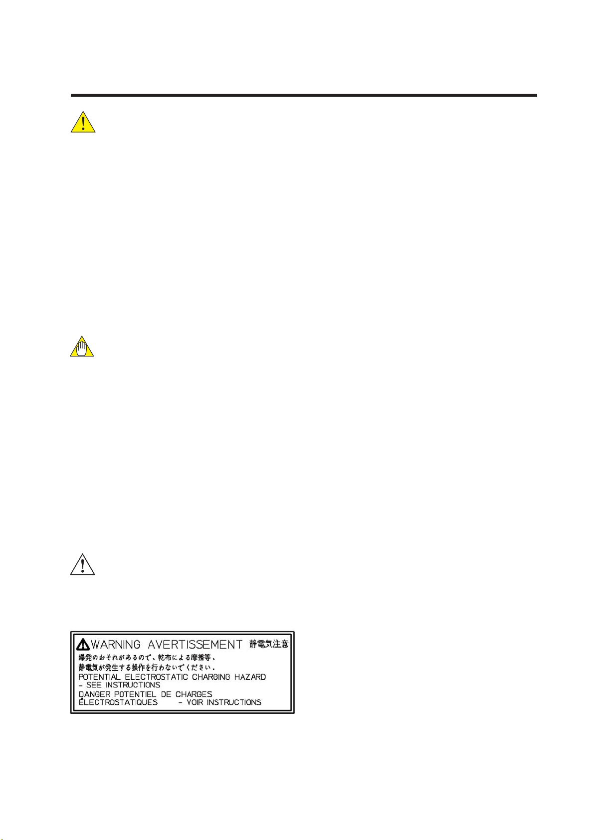
Electrostatic charge may cause an explosion hazard.
Avoid any actions that cause the generation of elec-
trostatic charge, e.g., rubbing with a dry cloth.
Warning label
Because the enclosure of the Dissolved Oxygen
transmitter Type ISC202S-A, -P, -F are made of alu-
minium, if it is mounted in an area where the use of
category 1 G Zone 0 apparatus is required, it must
be installed such, that, even in the event of rare
incidents, ignition sources due to impact and friction
sparks are excluded.
DANGERDANGER
CAUTIONCAUTION
WARNING
WARNING
Notice
• This manual should be passed on to the end
user.
• The contents of this manual are subject to
change without prior notice.
• The contents of this manual shall not be
reproduced or copied, in part or in whole,
without permission.
• This manual explains the functions contained in
this product, but does not warrant that they are
suitable the particular purpose of the user.
• Every effort has been made to ensure accuracy
in the preparation of this manual.
However, when you realize mistaken
expressions or omissions, please contact the
nearest Yokogawa Electric representative or
sales office.
• This manual does not cover the special
specifications. This manual may be left
unchanged on any change of specification,
construction or parts when the change does
not affect the functions or performance of the
product.
• If the product is not used in a manner specified
in this manual, the safety of this product may be
impaired.
Yokogawa is not responsible for damage to the
instrument, poor performance of the instrument
or losses resulting from such, if the problems are
caused by:
• Improper operation by the user.
• Use of the instrument in improper applications
• Use of the instrument in an improper
environment or improper utility program
• Repair or modification of the related instrument
by an engineer not authorized by Yokogawa.
Safety and Modification Precautions
• Follow the safety precautions in this manual
when using the product to ensure protection and
safety of the human body, the product and the
system containing the product.
IM 12D06A03-01E
The following safety symbols are used on the
product as well as in this manual.
DANGER
This symbol indicates that an operator must
follow the instructions laid out in this manual in
order to avoid the risks, for the human body, of
injury, electric shock, or fatalities. The manual
describes what special care the operator must
take to avoid such risks.
This symbol indicates that the operator must
refer to the instructions in this manual in
order to prevent the instrument (hardware) or
software from being damaged, or a system
failure from occurring.
This symbol gives information essential for
understanding the operations and functions.
This symbol indicates Protective Ground
Terminal
This symbol indicates Function Ground
Terminal (Do not use this terminal as the
protective ground terminal.)
This symbol indicates Alternating current.
This symbol indicates Direct current.
DANGERDANGER
WARNINGWARNING
CAUTIONCAUTION
Warranty and service
Yokogawa products and parts are guaranteed
free from defects in workmanship and material
under normal use and service for a period of
(typically) 12 months from the date of shipment
from the manufacturer. Individual sales organi-
zations can deviate from the typical warranty
period, and the conditions of sale relating to the
original purchase order should be consulted.
Damage caused by wear and tear, inadequate
maintenance, corrosion, or by the effects of
chemical processes are excluded from this war-
ranty coverage.
In the event of warranty claim, the defective
goods should be sent (freight paid) to the service
department of the relevant sales organization for
repair or replacement (at Yokogawa discretion).
The following information must be included in the
letter accompanying the returned goods:
• Part number, model code and serial number
• Original purchase order and date
• Length of time in service and a description of
the process
• Description of the fault, and the circumstances
of failure
• Process/environmental conditions that may be
related to the installation failure of the device
• A statement whether warranty or non-warranty
service is requested
• Complete shipping and billing instructions for
return of material, plus the name and phone
number of a contact person who can be
reached for further information.
Returned goods that have been in contact with
process fluids must be decontaminated/disin-
fected before shipment. Goods should carry a
certificate to this effect, for the health and safety
of our employees. Material safety data sheets
should also be included for all components of
the processes to which the equipment has been
exposed.
IM 12D06A03-01E
ATEX Documentation
This procedure is only applicable to the countries
in European Union.
GB
All instruction manuals for ATEX Ex related prod-
ucts are available in English, German and French.
Should you require Ex related instructions in your
local language, you are to contact your nearest
Yokogawa office or representative.
DK
Alle brugervejledninger for produkter relateret
til ATEX Ex er tilgængelige på engelsk, tysk og
fransk. Skulle De ønske yderligere oplysninger
om håndtering af Ex produkter på eget sprog, kan
De rette henvendelse herom til den nærmeste
Yokogawa afdeling eller forhandler.
I
Tutti i manuali operativi di prodotti ATEX con-
trassegnati con Ex sono disponibili in inglese,
tedesco e francese. Se si desidera ricevere i man-
uali operativi di prodotti Ex in lingua locale, met-
tersi in contatto con l’ufficio Yokogawa più vicino o
con un rappresentante.
E
Todos los manuales de instrucciones para los pro-
ductos antiexplosivos de ATEX están disponibles
en inglés, alemán y francés. Si desea solicitar las
instrucciones de estos artículos antiexplosivos en
su idioma local, deberá ponerse en contacto con
la oficina o el representante de Yokogawa más
cercano.
NL
Alle handleidingen voor producten die te maken
hebben met ATEX explosiebeveiliging (Ex)
zijn verkrijgbaar in het Engels, Duits en Frans.
Neem, indien u aanwijzingen op het gebied van
explosiebeveiliging nodig hebt in uw eigen taal,
contact op met de dichtstbijzijnde vestiging van
Yokogawa of met een vertegenwoordiger.
SF
Kaikkien ATEX Ex -tyyppisten tuotteiden käyt-
töhjeet ovat saatavilla englannin-, saksan- ja
ranskankielisinä. Mikäli tarvitsette Ex -tyyppisten
tuotteiden ohjeita omalla paikallisella kielellännne,
ottakaa yhteyttä lähimpään Yokogawa-toimistoon
tai -edustajaan.
P
Todos os manuais de instruções referentes aos
produtos Ex da ATEX estão disponíveis em Inglês,
Alemão e Francês. Se necessitar de instruções na
sua língua relacionadas com produtos Ex, deverá
entrar em contacto com a delegação mais próxima
ou com um representante da Yokogawa.
F
Tous les manuels d’instruction des produits
ATEX Ex sont disponibles en langue anglaise,
allemande et française. Si vous nécessitez des
instructions relatives aux produits Ex dans votre
langue, veuillez bien contacter votre représentant
Yokogawa le plus proche.
D
Alle Betriebsanleitungen für ATEX Ex bezogene
Produkte stehen in den Sprachen Englisch,
Deutsch und Französisch zur Verfügung. Sollten
Sie die Betriebsanleitungen für Ex-Produkte in
Ihrer Landessprache benötigen, setzen Sie sich
bitte mit Ihrem örtlichen Yokogawa-Vertreter in
Verbindung.
S
Alla instruktionsböcker för ATEX Ex (explosions-
säkra) produkter är tillgängliga på engelska, tyska
och franska. Om Ni behöver instruktioner för
dessa explosionssäkra produkter på annat språk,
skall Ni kontakta närmaste Yokogawakontor eller
representant.
GR
IM 12D06A03-01E
LT
LV
PL
EST
SLO
H
BG
RO
M
CZ
SK
IM 12D06A03-01E
Introduction 1-1
1. INTRODUCTION AND GENERAL DESCRIPTION
The Yokogawa EXA 202 is a 2-wire transmitter designed for industrial process monitoring, measurement
and control applications. This user’s manual contains the information needed to install, set up, operate
and maintain the unit correctly. This manual also includes a basic troubleshooting guide to answer typi-
cal user questions.
Yokogawa can not be responsible for the performance of the EXA transmitter if these instructions are not
followed.
1-1. Instrument check
Upon delivery, unpack the instrument carefully and inspect it to ensure that it was not damaged during
shipment. If damage is found, retain the original packing materials (including the outer box) and then
immediately notify the carrier and the relevant Yokogawa sales office.
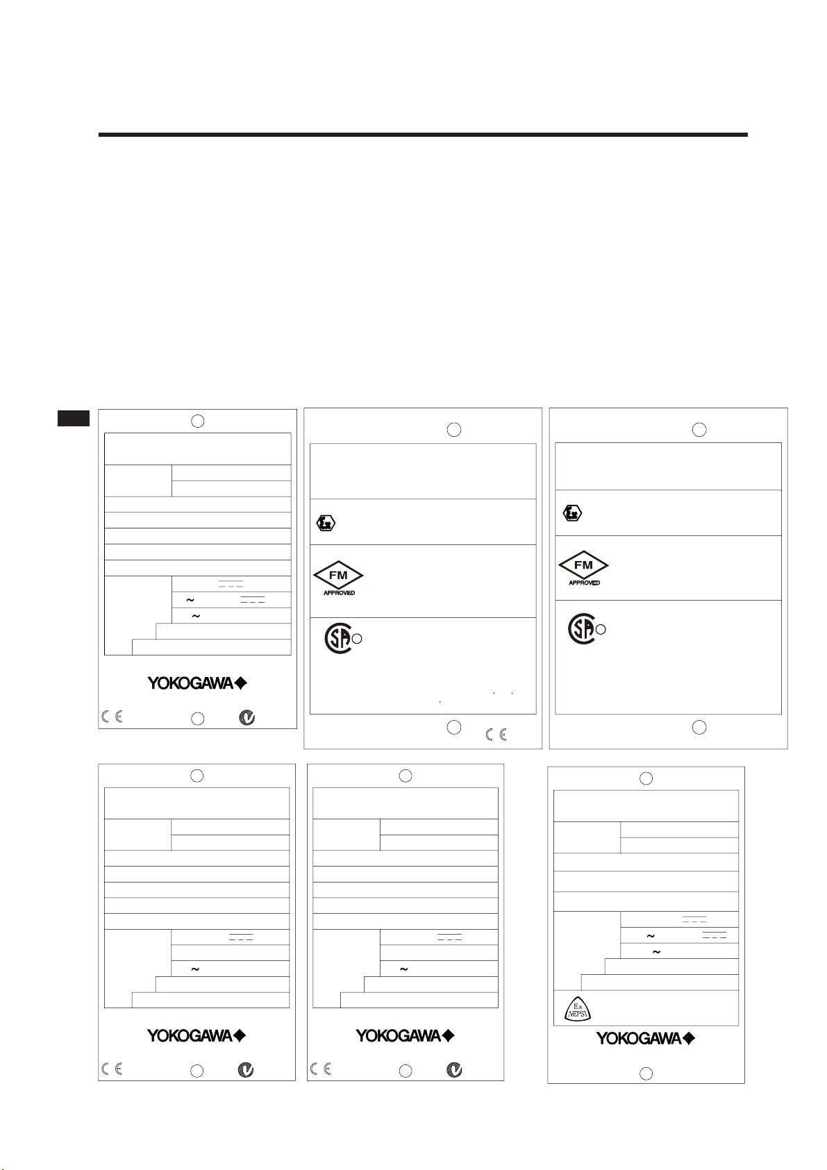
Make sure the model number on the textplate affixed to the side of the instrument agrees with your
order. Examples of nameplates are shown below.
No. IECEx KEM 06.0054X
ISC202S-N
II 3 G
Ex nA[nL] IIC T4
Ex nA[nL] IIC T6 for Ta:40
°C
IP65
SEE CONTROL DRAWING
No. KEMA 06ATEX0223
EEx nA[nL] IIC T4
EEx nA[nL] IIC T6 for Ta:40
°C
IP65
SEE CONTROL DRAWING
NI CL I, DIV 2, GP ABCD AND
CL I, ZN 2, GP IIC
T4
WARNING
Substitution of
components may
impair suitability
for class I, Division 2.
AVERTISSEMENT
La substitution de composants
peut rendre ce materiel
inacceptable pour les
emplacements de
Classe I, Division 2.
Ex nA[nL] IIC
NI CL I, DIV 2, GP ABCD
T4
T6 for Ta:40
°C
SEE CONTROL DRAWING
LR81741 C
R
Type 4X
Install per CONTROL DRAWING
IKE028-A10 P.7 to P.8
IP65 Type 3S
N200
MODEL
SUFFIX
SUPPLY
OUTPUT
AMB.TEMP.
STYLE
ISC202
-10 55°C
4 20mA DC
Made in Japan Tokyo 180-8750 JAPAN
No.
24V DC
ISC TRANSMITTER
No. IECEx KEM 06.0054X
ISC202S-A
No. KEMA 06ATEX0222 X
Ex ia IIC T4
Ex ia IIC T6 for Ta:40
°C
SEE CONTROL DRAWING
IS CL I, DIV 1, GP ABCD
AND AEx ia IIC
T4
Zone 0 Ex ia IIC T4
Zone 0 Ex ia IIC T6 for Ta:40
°C
IP65
SEE CONTROL DRAWING
II 1G
LR81741 C
CL I, DIV 1, GP ABCD
Ex ia IIC T4
Ex ia IIC T6 for Ta:40
°C
SEE CONTROL DRAWING
WARNING
Substitution of
components may impair
intrinsic safety
AVERTISSEMENT
intrinseque.
peut compromeltre la securite
La substitution de composants
R
IP65
Type 4X
Install per CONTROL DRAWING
IKE028-A10 P.5 to P.6
IP65 Type 3S
0344
Figure 1-1. Nameplate
mA
N200
MODEL
SUFFIX
SUPPLY
OUTPUT
AMB.TEMP.
STYLE
ISC202G-F
-10 55°C
FF-TYPE113
Made in Japan Tokyo 180-8750 JAPAN
No.
9 TO 32VDC
DISSOLVED OXYGEN TRANSMITTER
N200
MODEL
SUFFIX
SUPPLY
OUTPUT
AMB.TEMP.
STYLE
ISC202G-P
-10 55°C
PROFIBUS-PA
Made in Japan Tokyo 180-8750 JAPAN
No.
9 TO 32VDC
DISSOLVED OXYGEN TRANSMITTER
MODEL
SUFFIX
SUPPLY
OUTPUT
AMB.TEMP.
STYLE
Made in Japan Tokyo 180-8750 JAPAN
No.
24V DC
-10 55°C
4 20mA DC
ISC202S-K
SEE USER’S MANUAL BEFORE USE
Ex ia IIC T6 for Ta:40
˚C
Ex ia IIC T4
Cert No. GYJ081158X
ISC TRANSMITTER
IM 12D06A03-01E
1-2 Introduction
NOTE:
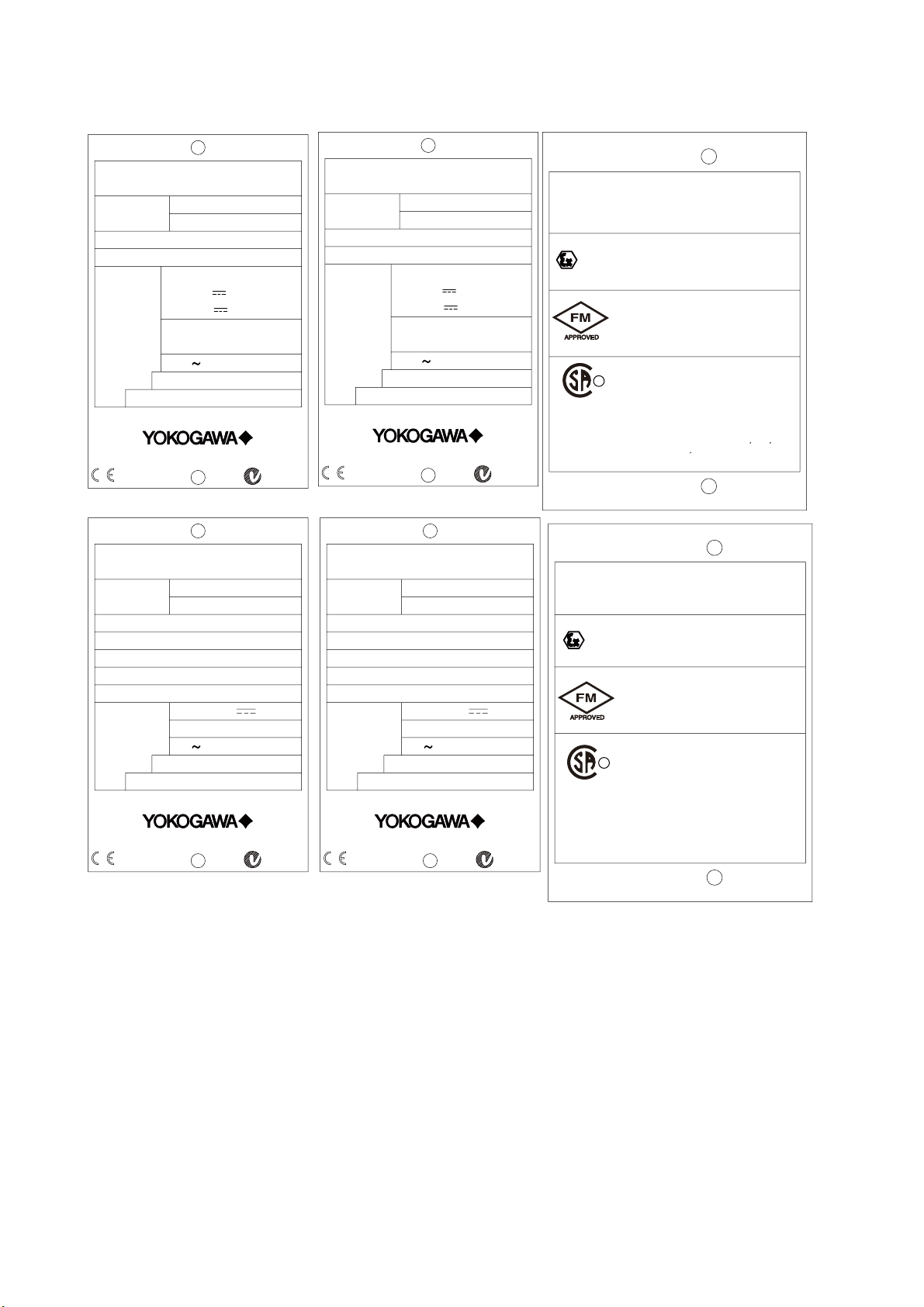
Check that all the parts are present, including mounting hardware, as specified in the option codes
at the end of the model number. For a description of the model codes, refer to Section 2 of this
manual under General Specifications.
Basic Parts List: Transmitter ISC202
User’s Manual English
Optional mounting hardware when specified (See model code)
Figure 1-2. Nameplate
N200
MODEL
SUFFIX
SUPPLY
OUTPUT
AMB.TEMP.
STYLE
ISC202S-B
-10 55°C
FF-TYPE 113
Made in Japan Tokyo 180-8750 JAPAN
No.
9 TO 32VDC
ISC TRANSMITTER
N200
MODEL
SUFFIX
SUPPLY
OUTPUT
AMB.TEMP.
STYLE
ISC202S-D
-10 55°C
PROFIBUS-PA
Made in Japan Tokyo 180-8750 JAPAN
No.
9 TO 32VDC
ISC TRANSMITTER
No.
ISC202S-B/-D
II 3 G
Ex nA[nL] IIC T4
Ex nA[nL] IIC T6 for Ta:40
°C
IP65
SEE CONTROL DRAWING
No.
EEx nA[nL] IIC T4
EEx nA[nL] IIC T6 for Ta:40
°C
IP65
SEE CONTROL DRAWING
NI CL I, DIV 2, GP ABCD AND
CL I, ZN 2, GP IIC
T4
WARNING
Substitution of
components may
impair suitability
for class I, Division 2.
AVERTISSEMENT
La substitution de composants
peut rendre ce materiel
inacceptable pour les
emplacements de
Classe I, Division 2.
Ex nA[nL] IIC
NI CL I, DIV 2, GP ABCD
T4
T6 for Ta:40
°C
SEE CONTROL DRAWING
LR81741 C
R
Type 4X
Install per CONTROL DRAWING
IKE029-A10 P.9 to P.10
IP65 Type 3S
KEMA 07ATEX0053
IECEx KEM 07.0028X
FNICO field device
N200
MODEL
SUFFIX
SUPPLY
OUTPUT
AMB.TEMP.
STYLE
ISC202S-F
-10 55°C
Made in Japan Tokyo 180-8750 JAPAN
No.
FISCO
17.5VDC
or 24VDC
/380mA/5.32W
/250mA/1.2W
FF-TYPE111 or 511
Li=0 μH, Ci=220pF
0344
ISC TRANSMITTER
N200
MODEL
SUFFIX
SUPPLY
OUTPUT
AMB.TEMP.
STYLE
ISC202S-P
-10 55°C
Made in Japan Tokyo 180-8750 JAPAN
No.
FISCO
17.5VDC
or 24VDC
/380mA/5.32W
/250mA/1.2W
PROFIBUS-PA
Li=0 μH, Ci=220pF
0344
ISC TRANSMITTER
No.
ISC202S-F/-P
No.
Ex ia IIC T4
SEE CONTROL DRAWING
IS CL I, DIV 1, GP ABCD
AND AEx ia IIC
T4
Zone 0 Ex ia IIC T4
IP65
SEE CONTROL DRAWING
FISCO field device
II 1G
LR81741 C
CL I, DIV 1, GP ABCD
Ex ia IIC T4
SEE CONTROL DRAWING
WARNING
Substitution of
components may impair
intrinsic safety
AVERTISSEMENT
intrinseque.
peut compromeltre la securite
La substitution de composants
R
Type 4X
Install per CONTROL DRAWING
IKE029-A10 P.5 to P.8
IP65 Type 3S
KEMA 07ATEX0052 X
IECEx KEM 07.0028X
IP65

IM 12D06A03-01E
Introduction 1-3
1-2. Application
The EXA transmitter is intended to be used for continuous on-line measurement in industrial installa-
tions. The unit combines simple operation and microprocessor-based performance with advanced self-
diagnostics and enhanced communications capability to meet the most advanced requirements. The
measurement can be used as part of an automated process control system. It can also be used to indi-
cate dangerous limits of a process, to monitor product quality, or to function as a simple controller for a
dosing/neutralization system.
Yokogawa designed the EXA transmitter to withstand harsh environments. The transmitter may be
installed
either indoors or outside because the IP65 and NEMA 4X housing and cabling glands ensure the unit is
adequately protected. The flexible polycarbonate window on the front door of the EXA allows pushbutton
access to the keypad, thus preserving the water and dust protection of the unit even during routine main-
tenance operations.
A variety of EXA hardware is optionally available to allow wall, pipe, or panel mounting. Selecting a prop-
er installation site will permit ease of operation. Sensors should normally be mounted close to the trans-
mitter in order to ensure easy calibration and peak performance. If the unit must be mounted remotely
from the sensors, WF10 extension cable can be used up to a maximum of 50 mtr (150 feet) with a BA10
junction box.
The EXA is delivered with a general purpose default setting for programmable items. (Default settings
are listed in Section 5 and again in Chapter 11). While this initial configuration allows easy start-up, the
configuration should be adjusted to suit each particular application. An example of an adjustable item is
the type of temperature sensor used. The EXA can be adjusted for two different types of temperature
sensors.
To record such configuration adjustments, write changes in the space provided in Chapter 11 of this
manual. Because the EXA is suitable for use as a monitor, a controller or an alarm instrument, program
configuration possibilities are numerous.
Details provided in this user’s manual are sufficient to operate the EXA with all Yokogawa sensor
systems and a wide range of third-party commercially available probes. For best results, read this manu-
al in conjunction with the corresponding sensor user’s manual.
Yokogawa designed and built the EXA to meet the CE regulatory standards. To assure the user of
continued accurate performance in even the most demanding industrial installations.

IM 12D06A03-01E
1-4 Introduction
IM 12D06A03-01E
Specifications 2-1
2-1. Specifications
A) Input specifications
: One inductive conductivity sensor and one
temperature sensor. Compatible with the
ISC40 series with integrated temperature sen-
sor. ISC202S: use with ISC40S
B) Input range
- Conductivity:
0 to 1999 mS/cm at 25 °C (77˚F)
reference temperature.
- Temperature:
-20 to 140 °C (4 to 284˚F)
- Cable length: max. 60 mtr (200 feet)
10 mtr (35 feet) fixed sensor
cable + 50 mtr (165 feet)
WF10 extension cable.
Influence of cable can be
adjusted by doing an
AIR CAL with the cable
connected to a dry cell.
C) Functional specifications
Accuracy (under reference conditions):
(Output span is 0 – 100 S/cm or more)
- Conductivity :
Linearity : ± (0.4 %FS + 0.3 S/cm)
Repeatability : ± (0.4 %FS + 0.3 S/cm)
- Temperature : ± 0.3ºC (0.6ºF)
Note: The following tolerance is added to the
above performance.
mA output tolerance: ±0.02 mA of
“4-20 mA”
- Step response 8 seconds for 90% (2
decade step).
E) Indicating range:
- Main display 0 to 1999 mS/cm (1
st
compensation)
- Message display 0 to 1999 mS/cm (2
nd
compensation),
Temperature -20 to 140 ºC
(0 to 280 ºF)
Concentration 0 to 100.0%
Temperature
compensation methods
NaCl, T.C., Matrix
mA- Output
Cell constant [cm
-1
]
Reference Temperature (ºC/ºF)
Software Release.
F) Transmission signal:
- General Isolated output of 4-20 mA
DC.Burn up (21 mA) or Burn
down (3.6 mA when HART
®
or distributor comm. is non-
used, 3.9 mA when HART®
or distributor comm. is used)
or pulse of 21 mA to signal
failure.
- Hold Outputs may be set to hold
the last or a fixed value during
maintenance.
G) Transmission range:
- Conductivity Minimum span: 100 S/cm
Maximum span: 1999 mS/cm
Setting value at 4 mA output:
90 % of setting value at 20
mA output
H) Serial Communication:
Bi-directional HART® digital communication
superimposed on the 4-20 mA signal.
I) DD specification
The ISC202G(S) Device Description (DD)
is available enabling communications with
the hand held communicator and compatible
devices. For more information contact your
local Yokogawa sales offices.
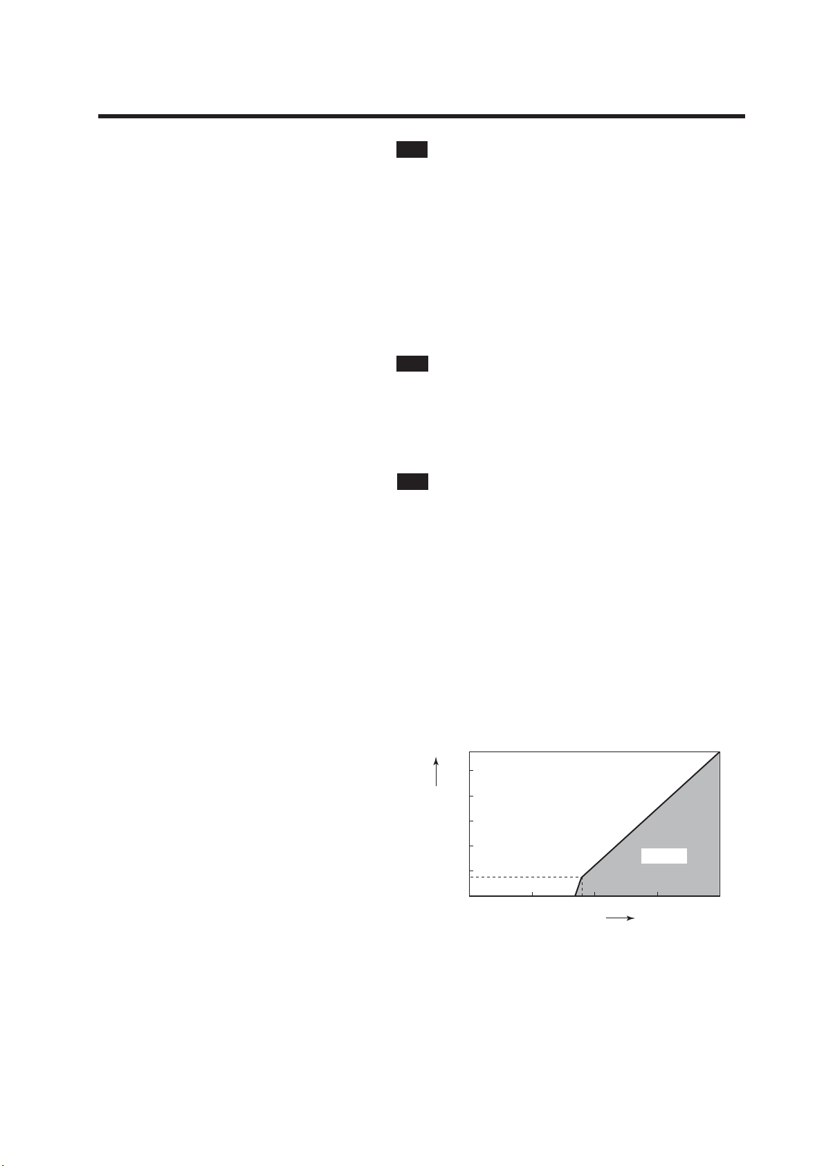
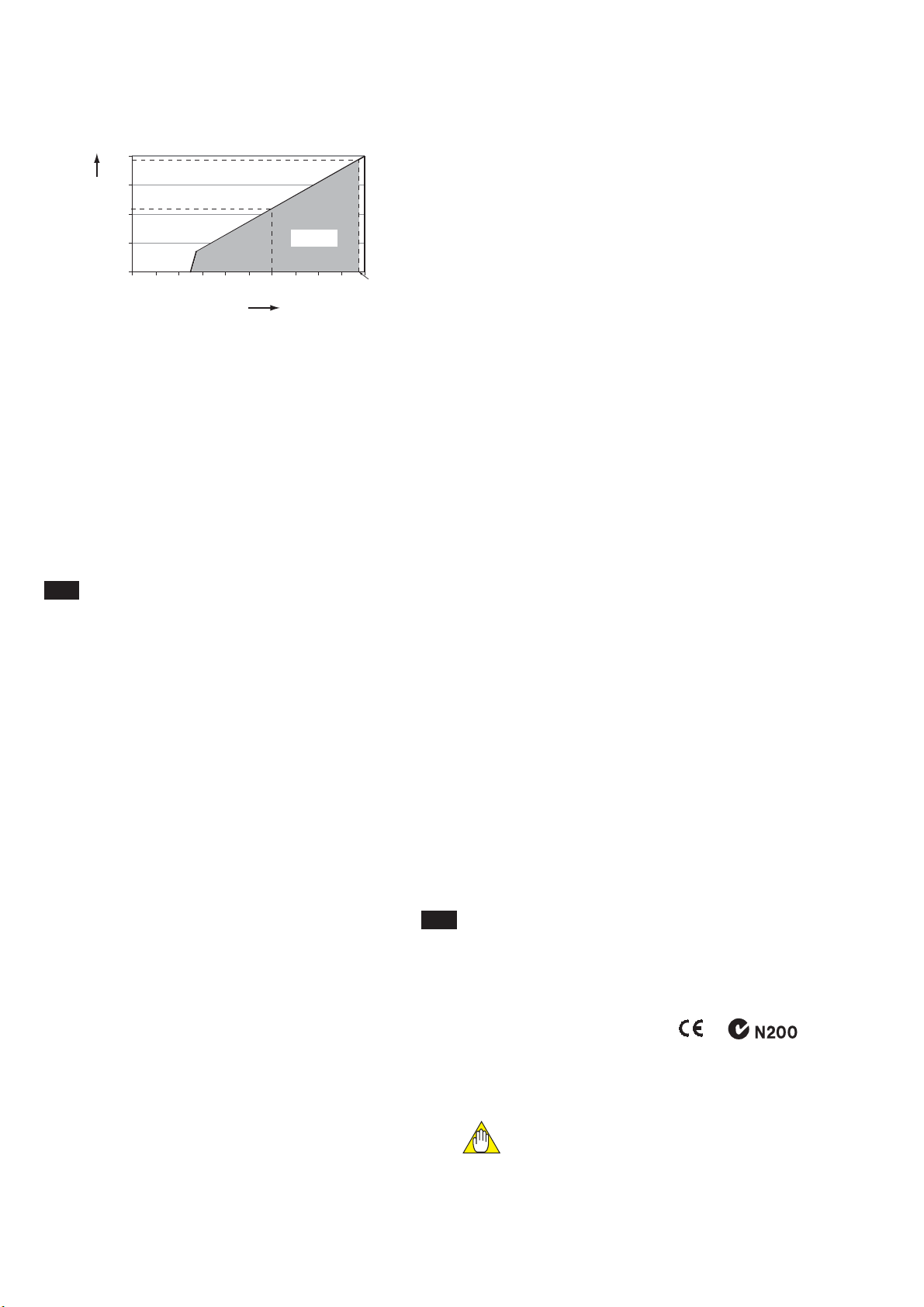
Maximum load resistance :
For the ISC202G, see figure 2-1.
200 or less with the PH201G
50 or less with the SDBT
For the ISC202S, see figure 2-2.
1000
1150
800
600
400
200
150
0
10 201817 30 400
Voltage (V)
Load Resistance ()
Possible
F05.EPS
Fig.2-1 Supply voltage/ load diagram for the ISC202G
mAmA
mAmA
mAmA
2. GENERAL SPECIFICATIONS
IM 12D06A03-01E
2-2 Specifications
0
200
400
600
800
12 16
17
20 24 28 32
425
775
Voltage (V)
Load Resistance ()
31.5 V
Possible
Fig.2-2 Supply voltage/ load diagram for the ISC202S
J) Temperature compensation:
- Sensor types: Pt1000 or 30k NTC
- Automatic:
-20 to 140 ºC (0 to 280 ºF)
- Algorithm:
selectable as mentioned below
NaCl according to IEC 60746-3
tables.
Two T.C. setting possible between
0.00 to 3.50 %/°C
Matrix: user selectable/
configurable. 8 selectable for
concentrated solutions, 1 free
programmable.
K) Sensor diagnostics:
Abnormal temperature (open, short), abnormal
conductivity values (E5/E6 free programmable),
e.g. dry cell, wiring problems.
L) Calibration:
Manual, calibration Input pre-measureds data
(cell constant).
M) Logbook:
Software record of important events and diag-
nostic data.
N) Display:
Custom liquid crystal display.
- Main display: 3½ digits, 12.5 mm high, zero
change included.
- Message display: 6 alphanumeric
characters, 7 mm high.
- Special fields: Flags for status indication :
FAIL and HOLD.
- Measuring units: S/cm or mS/cm
- Key prompts:
YES, NO, >, ^, ENT, Menu pointer
- Keys: 6 keys operated through
flexible window with tactile
feedback. One hidden key
behind the front cover.
O) Power supply:
Power supply : Normal 24 V DC loop powered
system, see Figure 2-1, 2-2.
ISC202G: 17 - 40 V DC
ISC202S: 17 - 31.5 V DC
- Input Isolation: Maximum 1000 VDC
mAmA
P) Housing:
- Material : Cast aluminium case with
chemically resistant coat-
ing, cover with flexible
polycarbonate window.
- Color : Case : Off-white (Equivalent to
Munsell 2.5Y8.4/1.2)
Cover : Deepsea Moss
green(Equivalent to Mun-
sell 0.6GY3.1/ 2.0)
- Cable gland : 2-Pg13.5
Q) Mounting:
Pipe, Wall or Panel.
R) Shipping details:
Package size : W x H x D, 290 x 300 x 290 mm
(11.5 x 11.8 x 11.5 inch).
S) Environment and operational conditions:
- Ambient temp.:
-10 to 55 ºC (+10 to +130 ºF)
LCD operational
temperature is specified
-
10 to 70 ºC (14 to 160 ºF)
Excursions to -30 to +70 ºC
will not damage the instrument.
- Storage temp.:
-30 to +70 ºC (-20 to +160 ºF).
- Relative humidity: 10 to 90% RH at 40 ºC
ambient temperature, non
condensing
- Data protection: EEPROM for configuration
and logbook. Battery
supported clock.
- Watchdog timer : Checks microprocessor.
- Automatic safeguard: Return to measurement
after 10 minutes when
no keystroke.
Operation protection: 3 digital pass codes (pro-
grammable).
Power down: No effect, reset to meas-
urement.
T) HART
®
specifications:
Minimum cable diameter: 0.51 mm, 24 AWG.
Maximum cable length: 1500 m
Refer to standard HART® specifications for more
details.
See www.hartcomm.org
U) EMC Conformity standard ,
EN 61326-1 Class A, Table 2
(For use in industrial locations)
EN 61326-2-3
EN 61326-2-5 (pending)
CAUTION
This instrument is a Class A product, and it is
designed for use in the industrial environment.
Please use this instrument in the industrial
environment only.
mAmA
IM 12D06A03-01E
Specifications 2-3
V) Explosionproof type
Refer to Control Drawings.
Item
Description
Code
Factory
Mutual (FM)
-N
-A
-N
-A
CENELEC
ATE X
2.EPS
FM Non-incendive safe Approval
Applicable standard: FM3600, FM3611, FM3810
Non-incendive Safe for Class I, Division 2,
Groups ABCD, Zone 2
Temp. Class: T4, Amb. Temp.: -10 to 55°C
Non-incendive Safe Apparatus Parameters
Vmax=31.5 V, Ci=22 nF, Li=35 H
FM Intrinsically safe Approval
Applicable standard: FM3600, FM3610, FM3810
Intrinsically Safe for Class I, Division 1, Groups ABCD
Class I, Zone 0, AEx ia IIC
Temp. Class: T4, Amb. Temp.: -10 to 55°C
Intrinsically Safe Apparatus Parameters
Vmax=31.5 V, Imax=100 mA,
Pmax=1.2 W, Ci=22 nF, Li=35 H
CENELEC ATEX (KEMA) Type of protection "n"
Applicable standard: EN60079-0:2006,
EN60079-15:2003
Certificate: KEMA 06ATEX0223
EEx nA [nL] IIC, Group: II, Category: 3G
Temp. Class: T4, Amb. Temp.: -10 to 55°C
T6, Amb. Temp.: -10 to 40°C
Ui=31.5 V, Ci=22 nF, Li=35 H
CENELEC ATEX (KEMA) Intrinsically safe Approval
Applicable standard: EN60079-0, EN50020
EN60079-26
Certificate: KEMA 06ATEX0222 X
Ex ia IIC, Group: II, Category: 1G
Temp. Class: T4, Amb. Temp.: -10 to 55°C
T6, Amb. Temp.: -10 to 40°C
Ui=31.5 V, Ii=100 mA, Pi=1.2 W, Ci=22 nF, Li=35 H
IECEx Type of protection "n"
Applicable standard: IEC 60079-15:2001,
IEC 60079-0:2004
Certificate: IECEx KEM 06.0054X
Ex nA [nL] IIC
Temp. Class: T4, Amb. Temp.: -10 to 55°C
T6, Amb. Temp.: -10 to 40°C
Ui=31.5 V, Ci=22 nF, Li=35 H
IECEx Intrinsically safe
Applicable standard: IEC 60079-0, IEC60079-11,
IEC60079-26
Certificate: IECEx KEM 06.0054X
Zone 0 Ex ia IIC
Temp. Class: T4, Amb. Temp.: -10 to 55°C
T6, Amb. Temp.: -10 to 40°C
Ui=31.5 V, Ii=100 mA, Pi=1.2 W, Ci=22 nF, Li=35 H
-N
-A
T12E.EPS
IECEx
Scheme
Item
Description
Code
CSA Non-incendive safe Approval or
type of protection "n"
Applicable standard: C22.2, No.0-M1991,
C22.2, No.04-M2004, C22.2, No.157-M1992,
C22.2, No.213-M1987, C22.2, No.61010-1
Class I, Division 2, Groups ABCD
Ex nA [nL] IIC
Temp. Class: T4, Amb. Temp.: -10 to 55°C
T6, Amb. Temp.: -10 to 40°C
Ui(Vmax)=31.5 V, Ci=22 nF, Li=35 H
-N
CSA Intrinsically safe Approval
Applicable standard: C22.2, No. 0-M1991,
C22.2, No. 04-M2004, C22.2, No. 157-M1992,
C22.2, No. 61010-1
Ex ia Class I, Division 1, Groups ABCD
Ex ia IIC
Temp. Class: T4, Amb. Temp.: -10 to 55°C
T6, Amb. Temp.: -10 to 40°C
Ui(Vmax)=31.5 V, Ii(Imax)=100 mA,
Pi(Pmax)=1.2 W, Ci=22 nF, Li=35 H
-A
Canadian
Standards
Association
(CSA)
mA
Item
Description
Code
Factory
Mutual (FM)
FM Non-incendive safe Approval
Applicable standard: FM3600, FM3611, FM3810
Non-incendive Safe for Class I, Division 2,
Groups ABCD, Zone 2
Temp. Class: T4, Amb. Temp.: -10 to 55°C
Non-incendive Safe Apparatus Parameters
FM Intrinsically safe Approval
Applicable standard: FM3600, FM3610, FM3810
Intrinsically Safe for Class I, Division 1, Groups ABCD
Class I, Zone 0, AEx ia IIC
Temp. Class: T4, Amb. Temp.: -10 to 55°C
Intrinsically Safe Apparatus Parameters
FM.EPS
Vmax=32 V, Pmax=1.2 W,
Ci=220 pF, Li=0 H
Vmax=32 V, Pmax=5.32 W,
Ci=220 pF, Li=0 H
Entity
FNICO
-F
-P
or
-D
-B
or
Vmax=24 V, Imax=250 mA,
Pmax=1.2 W, Ci=220 pF, Li=0 H
Vmax=17.5 V, Imax=380 mA,
Pmax=5.32 W, Ci=220pF, Li=0 H
Entity
FISCO
Item
Description
Code
CENELEC ATEX (KEMA) Type of protection "n"
Applicable standard: EN60079-0:2006,
EN60079-15:2003
Certificate: KEMA 07ATEX0053
EEx nA [nL] IIC, Group: II, Category: 3G
Temp. Class: T4, Amb. Temp.: -10 to 55°C
T6, Amb. Temp.: -10 to 40°C
Ui=32 V, Ci=220 pF, Li=0 H
CENELEC ATEX (KEMA) Intrinsically safe Approval
Applicable standard: EN60079-0, EN50020
EN60079-26
Certificate: KEMA 07ATEX0052 X
Ex ia IIC, Group: II, Category: 1G
Temp. Class: T4, Amb. Temp.: -10 to 55°C
Ui=24 V, Ii=250 mA, Pi=1.2 W, Ci=220 pF, Li=0 H
CENELEC
ATE X
ATEX.EPS
Entity
CENELEC
ATE X
CENELEC
ATE X
FISCO
-F
-P
or
-D
-B
or
CENELEC ATEX (KEMA) Intrinsically safe Approval
Applicable standard: EN60079-0, EN50020
EN60079-26, EN60079-27
Certificate: KEMA 07ATEX0052 X
Ex ia IIC, Group: II, Category: 1G
Temp. Class: T4, Amb. Temp.: -10 to 55°C
Ui=17.5 V, Ii=380 mA, Pi=5.32 W, Ci=220 pF, Li=0 H
Item
Description
Code
IEC.EPS
Entity
FISCO
-F
-P
or
-D
-B
or
IECEx Type of protection "n"
Applicable standard: IEC 60079-15:2001,
IEC 60079-0:2004
Certificate: IECEx KEM 07.0028X
Ex nA [nL] IIC
Temp. Class: T4, Amb. Temp.: -10 to 55°C
T6, Amb. Temp.: -10 to 40°C
Ui=32 V, Ci=220 pF, Li=0 H
IECEx Intrinsically safe
Applicable standard: IEC 60079-0, IEC60079-11,
IEC60079-26
Certificate: IECEx KEM 07.0028X
Zone 0 Ex ia IIC
Temp. Class: T4, Amb. Temp.: -10 to 55°C
Ui=24 V, Ii=250 mA, Pi=1.2 W, Ci=220 pF, Li=0 H
IECEx Intrinsically safe
Applicable standard: IEC 60079-0, IEC60079-11,
IEC60079-26, IEC60079-27
Certificate: IECEx KEM 07.0028X
Zone 0 Ex ia IIC
Temp. Class: T4, Amb. Temp.: -10 to 55°C
Ui=17.5 V, Ii=380 mA, Pi=5.32 W, Ci=220 pF, Li=0 H
IECEx
Scheme
IECEx
Scheme
IECEx
Scheme
mA
Item
Description
Code
CSA Non-incendive safe Approval or
type of protection "n"
Applicable standard: C22.2, No.0-M1991,
C22.2, No.04-M2004, C22.2, No.157-M1992,
C22.2, No.213-M1987, C22.2, No. 61010-1
Class I, Division 2, Groups ABCD
Ex nA [nL] IIC
Temp. Class: T4, Amb. Temp.: -10 to 55°C
T6, Amb. Temp.: -10 to 40°C
CSA Intrinsically safe Approval
Applicable standard: C22.2, No. 0-M1991,
C22.2, No. 04-M2004, C22.2, No. 157-M1992,
C22.2, No. 61010-1
Ex ia Class I, Division 1, Groups ABCD
Ex ia IIC
Temp. Class: T4, Amb. Temp.: -10 to 55°C
CSA.EPS
Canadian
Standards
Association
(CSA)
Ui(Vmax)=24 V, Ii(Imax)=250 mA,
Pi(Pmax)=1.2 W, Ci=220 pF, Li=0 H
Ui(Vmax)=17.5 V, Ii(Imax)=380 mA,
Pi(Pmax)=5.32 W, Ci=220 pF, Li=0 H
Entity
FISCO
Ui(Vmax)=32 V, Ci=220 pF, Li=0 H
Ui(Vmax)=32 V, Ci=220 pF, Li=0 H
Entity:
FNICO:
-F
-P
or
-D
-B
or

IM 12D06A03-01E
2-4 Specifications
NEPSI Certification (ISC202S-K)
NEPSI Intrinsically Safe Type
Cert No. GYJ081158X
• Applicable Standard:
GB3836.1-2000, GB3836.4-2000
• Type of Protection and Marking Code:
Ex ia IIC T4/T6
• Ambient Temperature :
T6; –10 to 40°C, T4; –10 to 55°C
Note 1 Entity Parameters
• Intrinsically safe input parameters
(terminal + and -):
Maximum Input Voltage (Ui) = 31.5 V
Maximum Input Current (Ii) = 100 mA
Maximum Input Power (Pi) = 1.2 W
Maximum Internal Capacitance (Ci) = 22 nF
Maximum Internal Inductance (Li) = 35 H
• Intrinsically safe output parameters and maximum
external parameters
(terminal 11 and 17):
Uo=14.4 V, Io=20 mA, Po=190 mW, Co=600
nF, Lo=88 mH
Note 2 Installation
• Electrostatic charges on the display window shall
be avoided.
• The external earth connection facility shall be
connected reliably.
• The instrument modification or parts replacement
by other than authorized representative of
Yokogawa Electric Corporation and will void
NEPSI Intrinsically safe certification.
• The user shall not change the configuration in
order to maintain/ensure the explosion protection
performance of the equipment. Any change may
impair safety.
• For installation, use and maintenance of
the product, the end user shall observe the
instruction manual and the following standards:
GB50257-1996 "Code for construction and
acceptance of electric device for explosion
atmospheres and fire hazard electrical
equipment installation engineering''.
GB3836.13-1997 "Electrical apparatus for
explosive gas atmospheres Part 13: Repair and
overhaul for apparatus used in explosive gas
atmospheres".
GB3836.15-2000 "Electrical apparatus for
explosive gas atmospheres- Part 15: Electrical
installations in hazardous area (other than
mines)" .
GB3836.16-2006 "Electrical apparatus for
explosive gas atmospheres- Part 16: lnspection
and maintenance of electrical installation (other
than mines)".
mA-HART
®
communication
A. Input : Two wire system 4-20 mA
B. Power supply :
ISC202G : up to 40 volts
ISC202S : up to 31.5 volts
Note: The transmitter contains a switched
power supply, drawing its energy
from the 0-4 mA section of the
signal. Consequently the 17 volt
limit is applied at 4 mA. The
characteristic of the unit is such that
above about 7 mA on the output, the
terminal voltage can drop to 14.5
volts without problem.
C. Transmission: Isolated output of 4 to 20 mA DC.
D. Signal : Maximum load 425 at 24 VDC.
(see fi gure 2-1)
Burn to signal failure acc.
NAMUR Recommendation NE43
(18.01.1994)
E. Operating range : 3.9 to 21 mA
F. Communication
: HART
®
, 1200 Baud, FSK
modulated on 4 to 20 mA signal
G. Configuration : Local with 6 keys
H. Software : Firmware based on Yokogawa stack.
I. Hardware :
Yokogawa HART® Modem F9197UB
J. Other Control systems
: Yokogawa PRM, Rosemount
AMS, Siemens PDM
K. Hand Terminal : Rosemount HHT 275/375
L. Other control systems: Yokogawa PRM, Rose-
mount AMS, Siemens PDM\
M. Output span :
- Conductivity : min 0.01S/cm, max. 1999 mS/
cm.
(max 90% zero suppression)
- Resistivity : min 0.001k
·cm, max.
999 M·cm.
(max 90% zero
suppression) The instrument
is user programmable for
linear or non-linear conductivity
ranges.
N. Cable specification
: 0.5 mm diameter or 24 AWG
over maximum length of 1500 m
O. DD specification
: The ISC202 Device Description
is available enabling
communications with the
Handheld Communicator and
compatible devices.
mA
mA

IM 12D06A03-01E
Specifications 2-5
PROFIBUS-PA communications
A. Input signal: Digital
B. Supply voltage: 9 to 32 V DC
C. Operating current: 26.0 mA
D. Operating values: According to IEC 1158-2
E. Bus connection
: Fieldbus interface base on
IEC1158-2 according to FISCO-
Model
F. Power supply: Power supply is achieved depend-
ant on the application by means of
segment coupler
G. Data transfer: According to PROFIBUS- PA pro-
file class B based on EN 50170
and DIN 19245 part 4
H. GSD file: The actual file can be down-
loaded from www.profibus.com
Configuration: Local with 6 keys
I. Software: Firmware based on Siemens
DPC31 stack.
J. Hardware:
PC- or PCMCIA-interfaces from
Siemens
K. Other control: Siemens PDM systems
L Electrical connection:
Terminals acc. to IEC 1158-2
M. Fieldbus-cable-types:
Twisted and shielded two
wire cable according to
recommendation based on IEC
1158-2 Cable diameter: 6 to 12
mm (0.24 to 0.47 inch)
FOUNDATION FIELDBUS H1 communications
A. Input signal: Digital
B. Supply voltage: 9 to 32 V DC
C. Operating current: 26.0 mA (base current)
D. Operating values: According to IEC 1158-2
E. Bus connection
: Fieldbus interface based on IEC
1158-2 according to FISCO-Model
F. Power supply:
Power supply is achieved
dependant on application by
means of segment coupler
G. Data transfer:
FF specification Rev. 1.4 Basic
device
H. Function blocks:
3 x AI, Transducer, Resource
I. Files: Actual file can be downloaded from
our homepage
J. Configuration: locally with 6 keys
K. Software:
National Instruments:
NI-FBUS configurator
L. Hardware: F-BUS interfaces from National
Instruments (AT-FBUS, PCMIA-
FBUS)
M. Other control systems:
YOKOGAWA PRM, DTM
IM 12D06A03-01E
2-6 Specifications
2. 2-wire Inductive conductivity transmitter (Explosionproof type)
Model Suffix Code Option Code Description
2-wire inductive conductivity transmitter
Intrinsic mA with HART (ATEX, CSA, FM)
Intrinsic mA with HART (NEPSI)
Intrinsic safe Profibus (ATEX, CSA, FM)
Intrinsic safe FF (ATEX, CSA, FM)
Non incendive FF (ATEX, CSA, FM) (*2)
Non incendive mA with HART (ATEX, CSA, FM) (*2)
Non incendive Profibus (ATEX, CSA, FM) (*2)
Japanese
English
Pipe, wall mounting bracket (Stainless steel)
Panel Mounting bracket(Stainless steel)
Hood for sun protection (Carbon steel)
Hood for sun protection (Stainless steel)
Stainless steel tag plate
G1/2
1/2NPT
Epoxy baked finish (*1)
/U
/PM
/H
/H2
/SCT
/AFTG
/ANSI
/X1
-A
-K
-P
-F
-B
-N
-D
-J
-E
ISC202S
Type
Language
Option Mounting Hardware
Hood
Tag Plate
Conduit Adapter
(*1) The housing is coated with epoxy resin.
(*2) When the instrument with Suffix Code "-B, -N, -D" is used, take measures so that the display window is not exposed
to direct sunlight.
[Style: S3]
2-2. Model and suffix codes
1. 2-wire Inductive conductivity transmitter (General purpose)
Model Suffix Code Option Code Description
2-wire Inductive conductivity transmitter
mA with HART
Profibus
FF
Japanese
English
Pipe, wall mounting bracket (Stainless steel)
Panel Mounting bracket(Stainless steel)
Hood for sun protection (Carbon steel)
Hood for sun protection (Stainless steel)
Stainless steel tag plate
G1/2
1/2NPT
Screw terminal (*1)
Epoxy baked finish (*2)
/U
/PM
/H
/H2
/SCT
/AFTG
/ANSI
/TB
/X1
-A
-P
-F
-J
-E
ISC202G
Type
Language
Option Mounting Hardware
Hood
Tag Plate
Conduit Adapter
(*1) It can be specified when the suffix code -A is selected.
(*2) The housing is coated with epoxy resin.
[Style: S2]
IM 12D06A03-01E
Specifications 2-7
2-3. Control Drawing ISC202S mA HART
®
Specification (IECEx).
・ Electrical data of the ISC202S.
- Supply and output circuit (terminals + and -):
Maximum input voltage U
i
= 31.5 V. Maximum input current I
i
= 100 mA.
Maximum input power P
i
= 1.2 W.
Effective internal capacitance C
i
= 22 nF.
Effective internal inductance L
i
= 35 PH.
- Sensor input circuit (terminals 11 through 17):
Maximum output voltage U
o
= 14.4 V. Maximum output current I
o
= 20 mA.
Maximum allowed external capacitance C
o
= 600 nF (for ISC202S-A),
C
o
= 3.5 PF (for ISC202S-N)
Maximum allowed external inductance L
o
= 88 mH (for ISC202S-A),
L
o
= 200mH (for ISC202S-N)
・ Barriers and power supply specification must not exceed the maximum values as
shown in the diagram above. These safety descriptions cover most of the commonly
used industry standard barriers, isolators and power supplies.
・ The Hand Held Communicator must be of a IECEx certified intrinsically safe type in
case it is used on the intrinsically safe circuit in the hazardous area or of a IECEx
certified non-incendive type in case it is used in the non-incendive circuit in the
hazardous area.
ISC202S
((Inductive Conductivity-transmitter)
Safe area
Uo = 31 .5 V o lt DC
Io = 100 mA
Po = 1.2 Watt
Ex ia or ib C er tifi e d R e p e a t e r
Power Supply
(HAR T Co mpa t ib le )
Output
Supply
ISC40S Sensor
terminals 11-17
+
_
G
ISC40S Sensor
terminals 11-17
Zone 0 or 1
Hazardous area Safe area
+
_
G
Functional
earth
Fanctional
earth
Intrins ic a lly s a fe d e s ig n
IECE x sta nd ard Ex ia IIC : T4 for a mb ient tem p . < 55 °C
T6 for ambient temp. < 40°C
ISC202S
+
_
Load
Resistance
Ex ia or ib
Certified safety b arrier or p o w e r
with Rint=300
:
Io = 100 mA
Uo = 31.5 Volt DC
Zone 0 or 1
Hazardous area
Fanctional
earth
+
_
24 volts DC Nominal
Sup p ly V olta g e .
Intrins ic a lly s a fe d e s ign
IECE x sta nd ard E x ia IIC : T 4 fo r am bie nt tem p. < 55 °C
T6 for a mb ient te m p. < 40 °C
(HAR T c omp atible)
(Induc tive C ond uc tivity-tra n sm itte r)
Certificate nr. IECEx KEM 06.0054X
Certificate nr. IECEx KEM 06.0054X
IM 12D06A03-01E
2-8 Specifications
2-4. Control Drawing ISC202S mA HART
®
Specification (ATEX)
ISC2 0 2 S
(Inductive Conduc tivity transmitter)
Safe area
Uo = 31 .5 V o lt DC
Io = 100 mA
Po = 1.2 Watt
EEx ia o r ib C e r tifie d Rep e a te r
Power Supply
(HA R T Com p a t ib le )
Output
Supply
ISC40S Sensor
terminals 11-17
(KEMA 00ATEX1067 X)
+
_
G
ISC40S Sensor
terminals 11-17
(KEMA 00ATEX1067 X)
Hazardous area Safe area
+
_
G
Functional
earth
Functional
earth
Intr insica lly s afe d esig n
CEN E LE C s tand ard E Ex ia IIC: T4 for amb ient temp . < 5 5° C
T6 for ambient temp. < 40°C
Certificate nr. KEM A 06ATEX 0222 X
ISC20 2S
+
_
Load
Resistance
EEx ia or ib
Certified safety barrier or power
with Rint=300
:
Io = 100 mA
Uo = 31.5 Volt DC
Hazardous area
Functional
earth
+
_
24 volts DC Nominal
Supply Voltage.
Intrinsically safe design
CENELE C s tan da rd EE x ia IIC : T 4 fo r am bie nt te mp . < 5 5° C
T6 for ambient temp.< 40°C
Certificate nr. KEM A 06ATEX 0222 X
(HART compatible)
(Indutive Condu c tivity tra ns m itter)
Zone 0 or 1
Zone 0 or 1
・ Electrical data of the ISC202S.
- Supply and output circuit (terminals + and -):
Maximum input voltage U
i
= 31.5 V. Maximum input current I
i
= 100 mA.
Maximum input power P
i
= 1.2 W.
Effective internal capacitance C
i
= 22 nF.
Effective internal inductance L
i
= 35 PH.
- Sensor input circuit (terminals 11 through 17):
Maximum output voltage U
o
= 14.4 V. Maximum output current I
o
= 20 mA.
Maximum allowed external capacitance C
o
= 600 nF (for ISC202S-A),
C
o
= 3.5 PF (for ISC202S-N)
Maximum allowed external inductance L
o
= 88 mH (for ISC202S-A),
L
o
= 200mH (for ISC202S-N)
・ Barriers and power supply specification must not exceed the maximum values as
shown in the diagram above. These safety descriptions cover most of the commonly
used industry standard barriers, isolators and power supplies.
・ The Hand Held Communicator must be of a ATEX certified intrinsically safe type in
case it is used on the intrinsically safe circuit in the hazardous area or of a ATEX
certified non-incendive type in case it is used in the non-incendive circuit in the
hazardous area.
IM 12D06A03-01E
Specifications 2-9
・ Electrical data of the ISC202S.
- Supply circuit (terminals + and -):
Maximum input voltage V
max
= 31.5 V. Maximum input current I
max
= 100 mA.
Maximum input power P
max
= 1.2 W.
Effective internal capacitance C
i
= 22 nF. Effective internal inductance L
i
= 35 PH.
- Sensor input circuit (terminals 11 through 17):
Maximum output voltage V
t
= 14.4 V. Maximum output current I
t
= 20 mA.
Maximum allowed external capacitance C
a
= 600 nF
Maximum allowed external inductance L
a
= 88 mH.
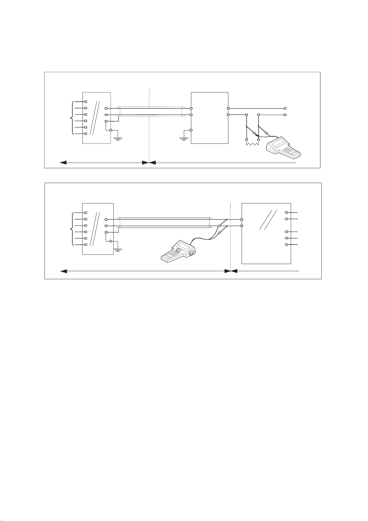
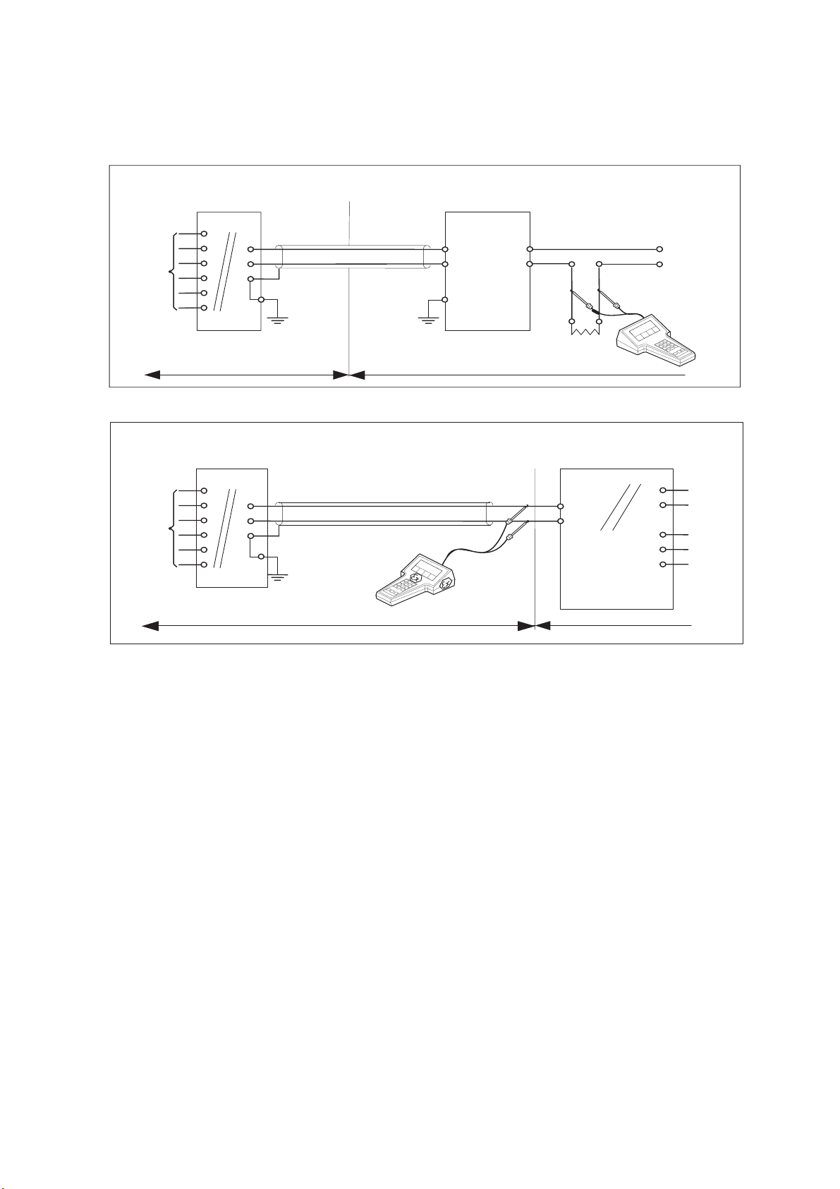
・If Hand Held Terminal (HHT) is not connected to the power supply lines of the ISC202S (see figure 1):
Any FM Approved barrier or power supply may be used that meets the following requirements.
V
oc
or V
t
d 31.5 V; I
sc
or I
t
d 100 mA; C
a
t 22nF + C
cable
; L
a
t 35PH + L
cable
If HHT is connected to the power supply lines of the ISC202S (see figure 2):
The Hand Held Terminal must be FM Approved. Refer to the manufacturers control drawing of the
HHT and the barrier/power supply to determine the cable parameters.
(V
oc
or V
t
) + V
HHT
d 31.5 V; (I
sc
or I
t
) + I
HHT
d 100 mA;
C
a
t 22nF + C
cable
+ C
HHT
; L
a
t 35P H + L
cable
+ L
HHT
When installing this equipment, follow the manufacturer’s installation drawing.
Installation should be in accordance with ANSI/ISA RP 12.06.01 “Installation of Intrinsically Safe
Systems for Hazardous (Classified) Locations” and the National Electrical Code (ANSI/NFPA 70).
Control equipment connected to the barrier/power supply must not use or generate more than 250
Vrms or Vdc.
・ Resistance between Intrinsically Safe Ground and earth ground must be less than 1.0 Ohm.
・ In case of using cable glands in Outdoor location, they shall be UV rated or made of metal.
WARNING
- Substitution of components may impair Intrinsic Safety
- To prevent ignition of flammable or combustible atmospheres, disconnect power before servicing or
read, understand and adhere to the manufacturer’s’live maintenance procedures.
ISC40S Sens o r
terminals 11-17
Max. cab lele ngth: 60 mtr.
Cable dia. : 3…12 mm.
ISC40S Sensor
terminals 11-17
Max. cablelength: 60 mtr.
Cable dia.: 3…12 mm.
Ùnclassified Location
FM Approved
Power Supply
(HART compatible)
Output
Supply
+
_
G
Classified Location
Unclassified Location
+
_
G
Functional
earth
Fanctional
earth
Intrinsically safe design
FM Class I, Div.1, Group ABCD, T4 for ambient temp. < 55°C
T6 for ambient temp. < 40°C
ISC202S transmitter
+
-
Load
Resistance
Classified Location
Fanctional
earth
+
_
24 volts DC N ominal
Supply Voltage.
FM Approved safety barrier or
power supply
with Rint = 300 :
(HART compatible)
For electrical data:
see text below.
For electrical data:
see text below.
Intrinsically safe design
FM Class I, Div.1, Group ABCD, T4 for ambient temp. < 55°C
T6 for ambient temp. < 40°C
ISC202S transmitter
Figure 1
Figure 2
2-5. Control Drawing ISC202S mA HART
®
Specification (FM Intrinsically safe design)
Application Doc. No.: IKE028-A10 P.5 to P.6
IM 12D06A03-01E
2-10 Specifications
・ Electrical data of the ISC202S.
- Supply circuit (terminals + and -):
Maximum input voltage V
max
= 31.5 V. Maximum input power P
max
= 1.2 W
Effective internal capacitance Ci = 22 nF Effective internal inductance Li = 35 H
- Sensor input circuit (terminals 11 through 17):
Maximum output voltage V
t
= 14.4 V. Maximum output current I
t
= 20 mA.
Maximum allowed external capacitance C
a
= 2.25 F.
Maximum allowed external inductance L
a
= 160 mH.
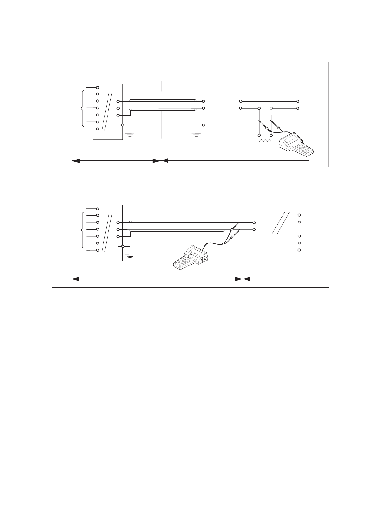
・ The Hand Held Terminal must be FM Approved in case it is used in the classified location.
When installing this equipment, follow the manufacturers installation drawing.
Installation shall be in accordance with Article 501.4(B) of the National Electrical Code
(ANSI/NFPA 79).
Non-incendive field wiring may be installed in accordance with Article 501 of the National
Electrical Code.
・ Grounding shall be in accordance with Article 250 of the National Electrical code
・ In case of using cable glands in Outdoor location, they shall be UV rated or made of metal.
WARNING
- Substitution of components may impair suitability for Division 2
- Do not remove or replace while circuit is live unless area is know to be non-hazardous
- Explosion Hazard – Do not disconnect equipment unless area is know to be non-hazardous
- Do not reset circuit breaker unless power has been removed from the equipment or the area is
know to be non-hazardous
ISC40S Sensor
terminals 11
-17
Max. cablelength: 60 mtr.
Cable dia. : 3…12 mm.
ISC40S Sensor
terminals 11
-17
Max. cablelength: 60 mtr.
Cable dia.: 3…12 mm
Ùnclassified Location
+
_
G
Classified Location Unclassified Location
+
_
G
Functional
earth
N
onincendive design
FM Class I, Div.2, Group ABCD, T4 for ambient temp. < 55°C
T6 for ambient temp. < 40°C
ISC202S transmitter
+
-
Load
Resistance
Classified Location
Functional
earth
FM Approved
p
ower supply
Voc
≤
31.5 V DC
For electrical data:
see text below.
For electrical data:
see text below.
N
onincendive design
FM Class I, Div.2, Group ABCD, T4 for ambient temp. < 55°C
T6 for ambient temp. < 40°C
ISC202S tramsmitter
+
-
FM Approved
p
ower supply
Voc
≤
31.5 VDC
2-6. Control Drawing ISC202S mA HART
®
Specification (FM Non-incendive design)
Application Doc. No.: IKE028-A10 P.7 to P.8
IM 12D06A03-01E
Specifications 2-11
2-7. Control Drawing of ISC202S mA HART
®
Specification (CSA)
Electrical data of the ISC202S.
- Supply and output circuit (terminals + and -)
Maximum input voltage V
max
= 31.5 V. Maximum input current I
max
= 100 mA.
Maximum input power P
max
= 1.2 W.
Effective internal capacitance C
i
= 22 nF. Effective internal inductance L
i
= 35 PH.
- Sensor input circuit (terminals 11 through 17):
Maximum output voltage V
oc
= 14.4 V. Maximum output current I
sc
= 20 mA.
Maximum allowed external capacitance C
a
= 600 nF.
Maximum allowed external inductance L
a
= 88 mH.
・ Barriers and power supply should be CSA certified. The specifications must not exceed
the maximum values as shown in the diagram above. Installation should be in
accordance with Canadian Electrical Code, Part I.
Maximum safe area voltage should not exceed 250 V
RMS
.
For Class I, Div. 2, Group ABCD the CSA certified barrier is not required, and the Sensor
input circuit (terminals 11 through 17) is non-incendive having the parameters:
Maximum output voltage V
oc
= 14.4 V.
Maximum output current I
sc
= 20 mA.
Maximum allowed external capacitance C
a
= 3.5μF.
Maximum allowed external inductance L
a
= 200 mH.
・The Hand Held Communicator must be of a CSA certified intrinsically safe type in case it
is used on the intrinsically safe circuit in the hazardous area, or of a CSA certified
non-incendive type in case it is used on the non-incendive circuit in the hazardous area.
Safe area
Vmax = 31.5 VoltDC
Imax = 100 mA
Pmax = 1.2 Watt
CSA certified
Power Supply
(HAR T com pa tible) )
Output
Supply
ISC40S Sensor
terminals 11-17
+
_
G
ISC40S Sensor
terminals 11-17
Hazardous area Safe area
+
_
G
Functional
earth
Functional
earth
Intrinsically safe design
CSA Ex ia Class I, Div.1, Group ABCD, T4 for ambient temp. < 55°C
T6 for ambient tem p. < 4 0° C
ISC202S transmitter
+
-
Load
Resistance
Imax = 100 mA
Vmax = 31.5 VoltDC
Hazardous area
Functional
earth
+
_
24 volts DC N o minal
Supply Voltage.
CSA c ertified sa fety b arrier o r
power supply with Rint=300 :
(HAR T c om p a tible)
Su it ab le v a lue s a r e:
For electrical data:
see text below.
For electrical data:
see text below.
Suitable v a lu es a re:
Intrinsically safe design
CSA E x ia C las s I, D iv.1 , G ro up A B C D , T4 for amb ient tem p. < 5 5 °C
T6 for ambient tem p . < 4 0 °C
ISC202S transmitter
IM 12D06A03-01E
2-12 Specifications
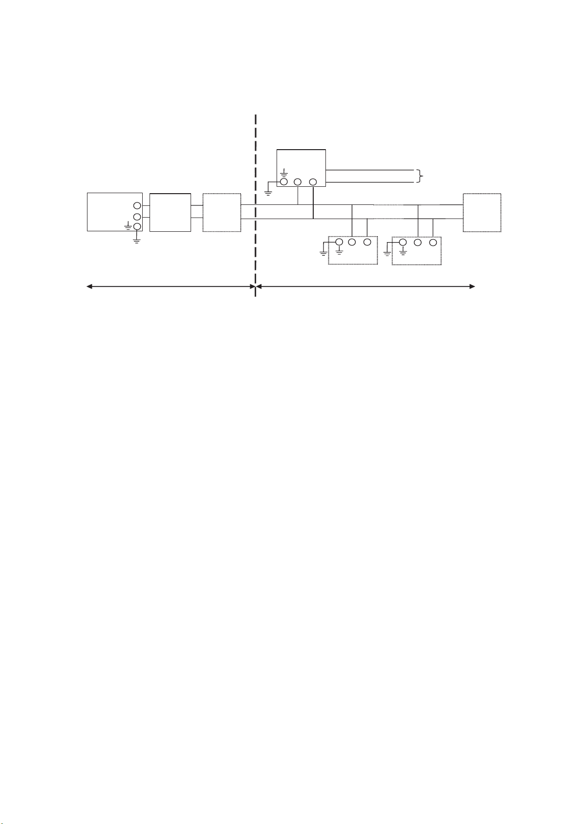
2-8. Control Drawing of ISC202S FF/PB Specification (IECEx)
Safe area
Hazardous area
Zone 0 or 1
Safe area
Apparatus
I.S.
interface
I.S.
certified
Terminator
Ui = 24 V or Ui = 17,5 V
Ii = 250 mA Ii= 380 mA
Pi = 1,2 W Pi = 5,32 W
Ex ia IIC
T4 for ambient te mp. d 55 q C
ISC202S-F
or ISC202S-P
I.S.
certified
Terminator
-
+
-
+
Transm itter
Transm itter
Sensor
Connections
-
+
-
+
x Sensor(s) are of a passive type to be regarded as 'simple apparatus'.
x Electrical data of the ISC202S-F & ISC202S-P:
- Supply and output circuit:
Maximum input voltage Ui = 24 V
Maximum input current Ii = 250 mA
Maximum input power Pi = 1.2 W
Effective internal capacitance Ci = 220 pF;
Effective internal inductance Li = 0 H.
or
FISCO field device
Maximum input voltage Ui =17.5 V
Maximum input current Ii =380 mA
Maximum input power Pi =5.32 W
Effective internal capacitance Ci = 220 pF;
Effective internal inductance Li = 0 H.
- Sensor input circuit:
Maximum output voltage Uo = 14.4 V; Maximum output current Io = 20 mA
Maximum allowed external capacitance Co = 600 nF
Maximum allowed external inductance Lo = 88 mH
x Any I.S. interface may be used that meets the following requirements:
Uo d 24 V
Io d 250 mA
Po d 1.2 W
Co t 220 pF + Ccable; Lo t 0 H + Lcable
or
FISCO power supply
Uo d 17.5 V
Io d 380mA
Po d 5.32 W
Co t 220 pF + Ccable; Lo t 0 H + Lcable
x Electrical data of the ISC202S-B & ISC202S-D (Type of protection “n”)
- Supply and output circuit:
Maximum input voltage Ui = 32 V
Effective internal capacitance Ci = 220 pF; Effective internal inductance Li = 0 H.
- Sensor input circuit:
Maximum output voltage Uo = 14.4 V; Maximum output current Io = 20 mA
Maximum allowed external capacitance Co = 3.5 F
Maximum allowed external inductance Lo = 200 mH
IM 12D06A03-01E
Specifications 2-13
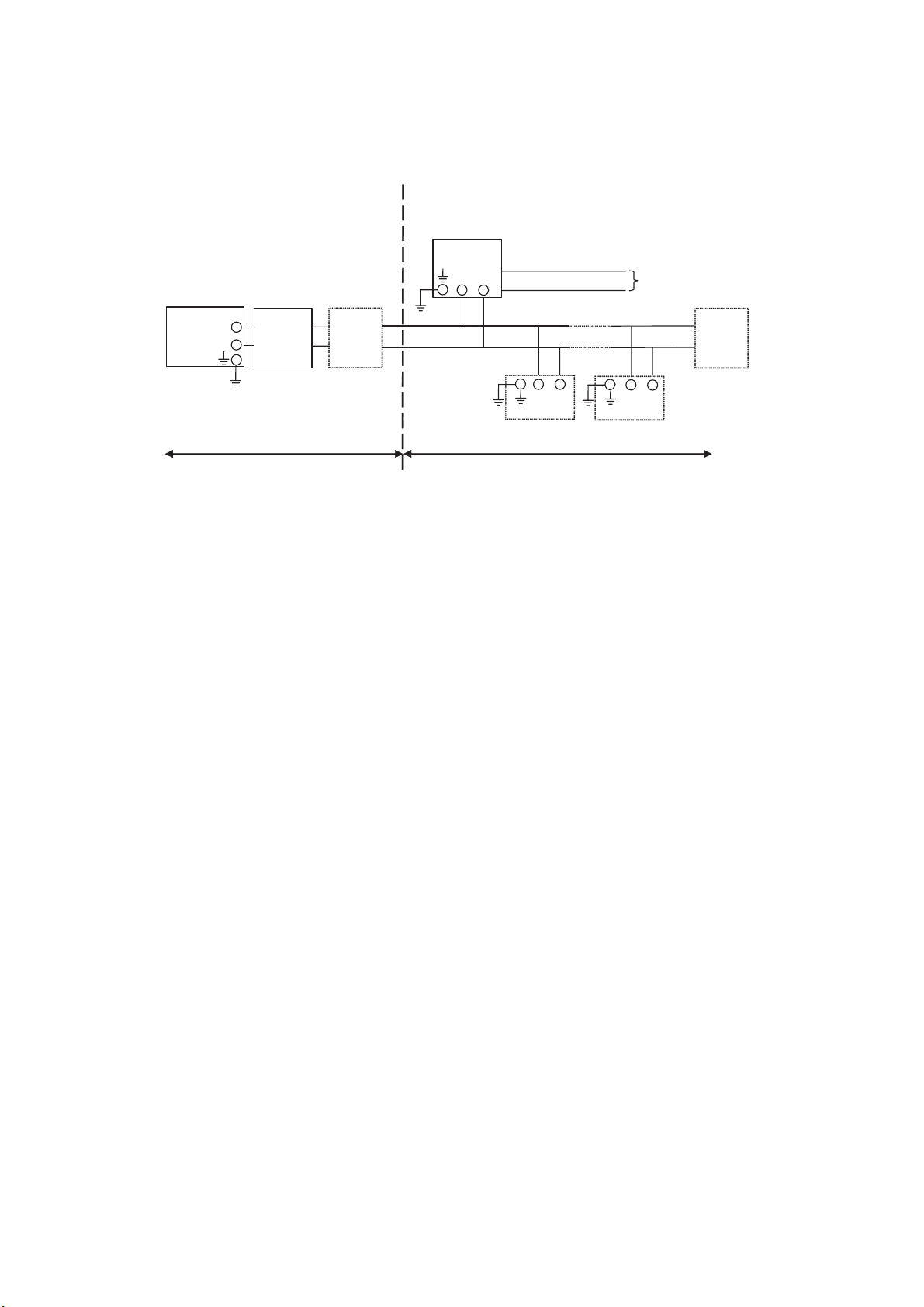
2-9. Control Drawing of ISC202S FF/PB Specification (ATEX)
Safe area
Hazardous area
Zone 0 or 1
Safe area
Apparatus
I.S.
interface
I.S.
certified
Terminator
Ui = 24 V or Ui = 17,5 V
Ii = 250 mA Ii= 380 mA
Pi = 1,2 W Pi = 5,32 W
Ex ia IIC
T4 for ambient temp. d 55 qC
ISC202S-F
o
r
ISC202S-P
I.S.
certified
Terminator
-
+
-
+
Transmitter
Transmitter
Sensor
Connections
-
+
-
+
x Sensor(s) are of a passive type to be regarded as 'simple apparatus'.
x Electrical data of the ISC202S-F & ISC202S-P:
- Supply and output circuit:
Maximum input voltage Ui =24 V
Maximum input current Ii =250 mA
Maximum input power Pi =1.2 W
Effective internal capacitance Ci = 220 pF;
Effective internal inductance Li = 0 H.
or
FISCO field device
Maximum input voltage Ui = 17.5 V
Maximum input current Ii = 380 mA
Maximum input power Pi = 5.32 W
Effective internal capacitance Ci = 220 pF;
Effective internal inductance Li = 0 H.
- Sensor input circuit:
Maximum output voltage Uo = 14.4V; Maximum output current Io = 20 mA
Maximum allowed external capacitance Co = 600 nF
Maximum allowed external inductance Lo = 88 mH
x Any I.S. interface may be used that meets the following requirements:
Uo d 24 V
Io d 250 mA
Po d 1.2 W
Co t 220 pF + Ccable; Lo t 0 H + Lcable
or
FISCO power supply
Uo d 17.5 V
Io d 380 mA
Po d 5.32 W
Co t 220 pF + Ccable; Lo t 0 H + Lcable
x Electrical data of the ISC202S-B & ISC202S-D (Type of protection “n”)
- Supply and output circuit:
Maximum input voltage Ui = 32 V
Effective internal capacitance Ci = 220 pF; Effective internal inductance Li = 0 H.
- Sensor input circuit:
Maximum output voltage Uo= 14.4 V; Maximum output current Io = 20 mA
Maximum allowed external capacitance Co = 3.5 F
Maximum allowed external inductance Lo = 200 mH
IM 12D06A03-01E
2-14 Specifications
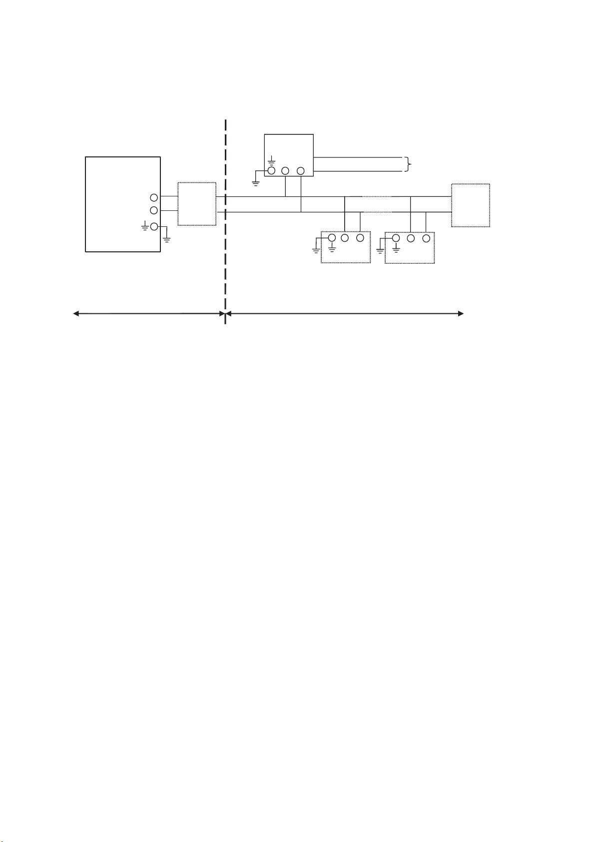
2-10. Control Drawing of ISC202S FF/PB Specification (FM Intrinsically safe Entity)
Unclassified Location
Classified Location
Division 1
FM Approved
barrier
Voc (Vt) d 24 V
Ioc (It) d 250 mA
Poc (Pt) d 1.2 W
Ca t 220pF+ Ccable
La t 0 H + Lcable
Sensor
Connections
Max. cablelength: 60 mtr.
Cable dia. : 3…12 mm.
FM Class I, DIV. 1, Group ABCD
T4 for ambient temp. d 55 qC
-
+
I.S.
certified
Terminator
I.S.
certified
Terminator
ISC202S-F
or ISC202S-P
Transmitter
Transmitter
-
+
Sensor
Connections
-
+
-
+
x Sensor(s) are of a passive type to be regarded as 'simple apparatus', devices which
neither store nor generate voltages over 1.5 V, currents over 0.1 A, power over 25 mW or
energy over 20 PJ, or are FM Approvals entity approved and meet connection
requirements.
x Electrical data of the ISC202S-F & ISC202S-P:
- Supply circuit:
Maximum input voltage Vmax = 24 V
Maximum input current Imax = 250 mA
Maximum input power Pi = 1.2 W
Effective internal capacitance Ci = 220 pF; Effective internal inductance Li = 0 PH.
- Sensor input circuit:
Maximum output voltage Vt = 14.4 V; Maximum output current It = 20 mA
Maximum allowed external capacitance Ca = 600 nF
Maximum allowed external inductance La = 88 mH
x Any FM Approved barrier may be used that meets the following requirements:
Voc or Vt d 24 V
Ioc or It d 250 mA
Poc or Pt d 1.2 W
Ca t 220 pF + Ccable; La t 0 H + Lcable
When installing this equipment, follow the manufacturer’s installation drawing.
Installation should be in accordance with ANSI/ISA RP 12.06.01 “Installation of
Intrinsically Safe Systems for Hazardous (Classified) Locations” and the National
Electrical Code (ANSI/NFPA 70).
Associated apparatus connected to the barrier must not use or generate more than
250 Vrms or Vdc.
x Resistance between Intrinsically Safe Ground and earth ground must be less than 1.0
Ohm.
x In case of using cable glands in Outdoor location, they shall be UV rated or made of metal.
WARNING
- Substitution of components may impair Intrinsic Safety
- To prevent ignition of flammable or combustible atmospheres, disconnect power
before servicing or read, understand and adhere to the manufacturer’s live
maintenance procedures.

IM 12D06A03-01E
Specifications 2-15
x The cable used to interconnect the devices needs to comply with the following
parameters:
Loop resistance R’: 15 … 150 /km; Inductance per unit length L’: 0,4 … 1 mH/km
Capacitance per unit length C’: 80 … 200 nF/km
(C’ = C’ line/line + 0,5 C’ line/screen if both line are floating)
(C’ = C’ line/line + C’ line/screen if the screen is connected to one line)
Length of spur cable: max. 30 m
Length of trunk cable: max. 1 km
Length of splice : max. 1 m
WARNING
- Substitution of components may impair Intrinsic Safety
- To prevent ignition of flammable or combustible atmospheres, disconnect power
before servicing or read, understand and adhere to the manufacturer’s live
maintenance procedures.
Application Doc. No.: IKE029-A10 P.5 to P.6
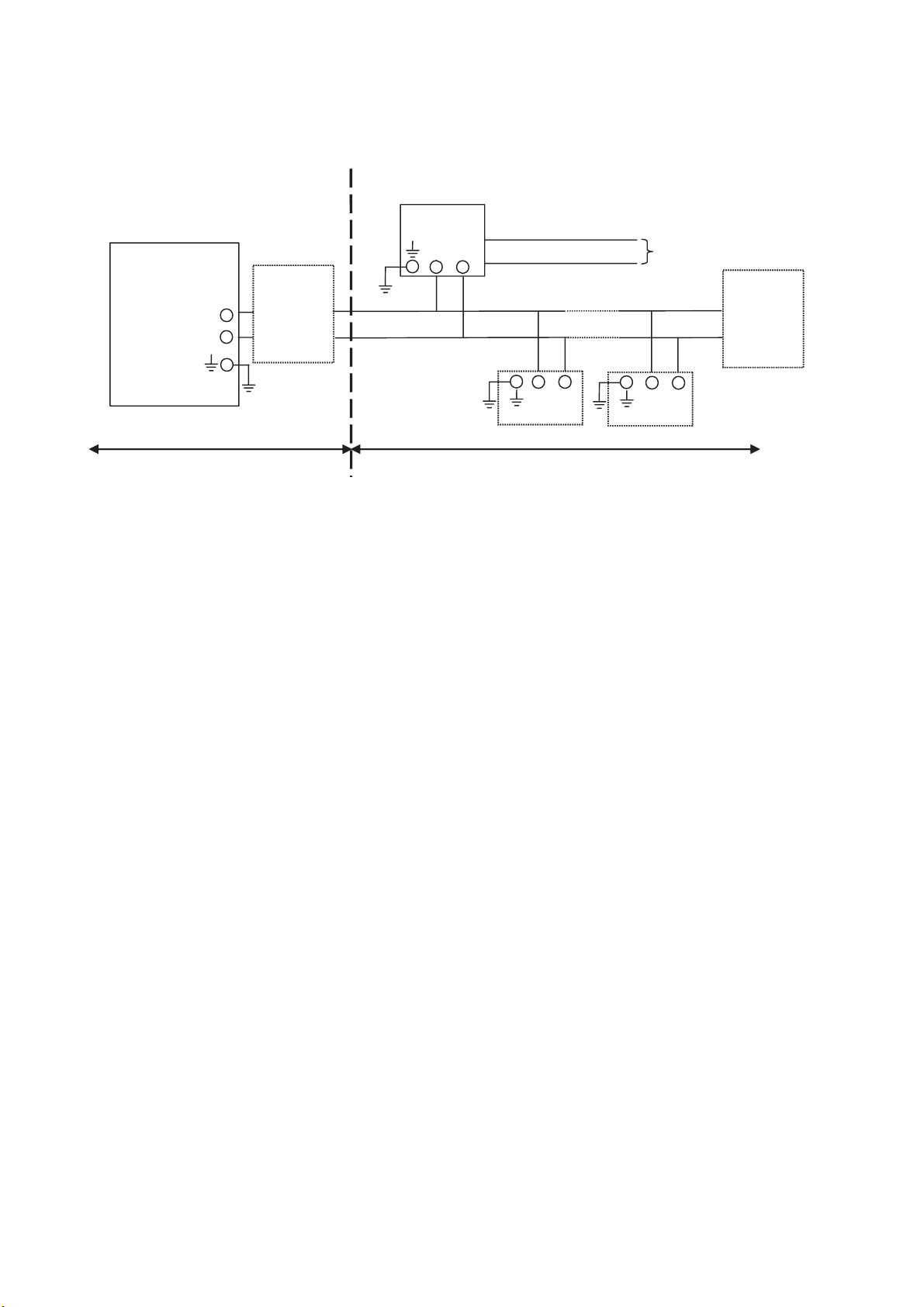
IM 12D06A03-01E
2-16 Specifications
2-11. Control Drawing of ISC202S FF/PB Specification (FM Intrinsically safe FISCO)
-
+
ISC202S-F
or ISC202S-P
Transmitter
-
+
Transmitter
Unclassified Location
Classified Location
Division 1
FM Approved
FISCO barrier
Voc (Vt) d17,5 V
Ioc (It) d380 mA
Poc (Pt) d5,32 W
Sensor
Connections
Max. cablelength: 60 mtr.
Cable dia. : 3…12 mm.
FM Class I, DIV. 1, Group ABCD
T4 for ambient temp. d 55 qC
Sensor
Connections
-
+
-
+
FM Approved
Terminator
R = 90..100
C = 0..2,2 F
FM Approved
Terminator
R = 90..100
C = 0..2,2 F
x Sensor(s) are of a passive type to be regarded as 'simple apparatus', devices which
neither store nor generate voltages over 1.5 V, currents over 0.1 A, power over 25 mW or
energy over 20 PJ, or are FM Approvals entity approved and meet connection
requirements.
x Electrical data of the ISC202S-F & ISC202S-P:
- Supply circuit: Vmax = 17.5 V; Imax = 380 mA; Pi = 5.32 W; Ci = 220 pF; Li = 0 H.
- Sensor input circuit: Vt = 14.4 V; It = 20 mA; Ca = 600 nF; La = 88 mH
x Any FM Approved FISCO barrier may be used that meets the following requirements:
Voc or Vt d 17.5 V; Ioc or It d 380 mA; Poc or Pt d 5.32 W
When installing this equipment, follow the manufacturer’s installation drawing.
Installation should be in accordance with ANSI/ISA RP 12.06.01 “Installation of
Intrinsically Safe Systems for Hazardous (Classified) Locations” and the National
Electrical Code (ANSI/NFPA 70).
Associated apparatus connected to the FISCO barrier must not use or generate more
than 250 Vrms or Vdc.
x Resistance between FISCO Intrinsically Safe Ground and earth ground must be less than
1.0 Ohm.
x In case of using cable glands in Outdoor location, they shall be UV rated or made of metal.
x The FISCO concept allows the interconnection of several I.S. apparatus not specifically
examined in such combination. The criterion for such interconnection is that the voltage
(Vmax), the current (Imax) and the power (Pi) which I.S. apparatus can receive and remain
intrinsically safe, considering faults, must be equal to or greater that the voltage (Voc, Vt),
the current (Ioc, It) and the power (Poc, Pt) which can be provided by the FM approved
FISCO barrier. In addition, the maximum unprotected residual capacitance (Ci) and
inductance (Li) of each apparatus (other than the terminator) connected to the Fieldbus
must be less than or equal to 5nF and 10 H respectively.

IM 12D06A03-01E
Specifications 2-17
x In each I.S. Fieldbus segment only one active source, normally the FM Approved FISCO
barrier, is allowed to provide the necessary power for the Fieldbus system. All other
equipment connected to the bus cable has to be passive (not providing energy to the
system), except to a leakage current of 50A for each connected device. Seperately
powered equipment needs a galvanic isolation to insure that the I.S. Fieldbus circuit
remains passive.
x The cable used to interconnect the devices needs to comply with the following
parameters:
Loop resistance R’: 15 … 150 /km; Inductance per unit length L’: 0.4 … 1 mH/km
Capacitance per unit length C’: 80 … 200 nF/km
(C’ = C’ line/line + 0,5 C’ line/screen if both line are floating)
(C’ = C’ line/line + C’ line/screen if the screen is connected to one line)
Length of spur cable: max. 30 m
Length of trunk cable: max. 1 km
Length of splice : max. 1 m
WARNING
- Substitution of components may impair Intrinsic Safety
- To prevent ignition of flammable or combustible atmospheres, disconnect power
before servicing or read, understand and adhere to the manufacturer’s live
maintenance procedures.
Application Doc. No.: IKE029-A10 P.7 to P.8
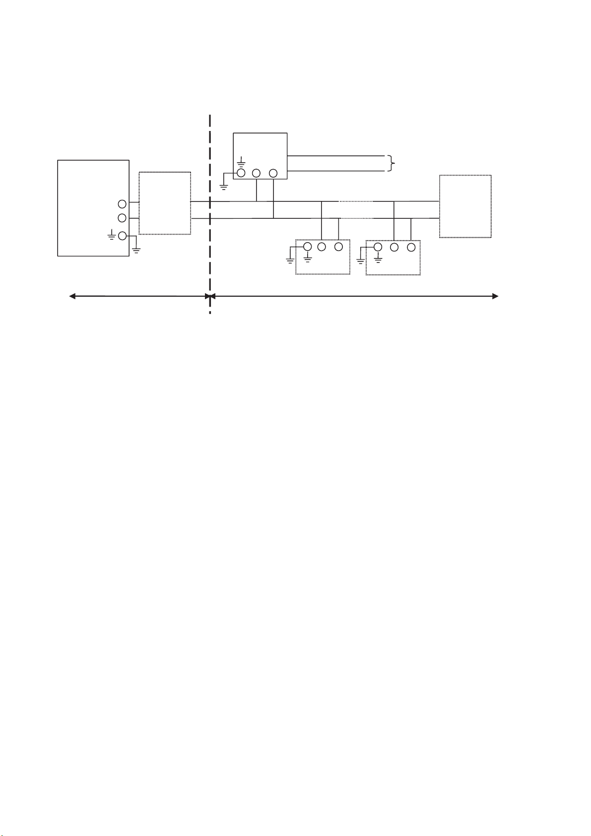
IM 12D06A03-01E
2-18 Specifications
ISC202S-B
or ISC202S-D
Transmitter
-
+
Transmitter
-
+
Unclassified Location
Classified Location
Division 2
FM Approved
Power Supply
Voc d 32 VDC
Sensor
Connections
Max. cablelength: 60 mtr.
Cable dia.: 3…12 mm.
FM Class I, DIV. 2, Group ABCD
T4 for ambient temp. d 55 qC
T6 for ambient tem
p
. d 40 qC
Sensor
Connections
-
+
-
+
FM Approved
Terminator
R = 90..100
C = 0..2,2 F
FM Approved
Terminator
R = 90..100
C = 0..2,2 F
x Sensor(s) are of a passive type to be regarded as 'simple apparatus', devices which
neither store nor generate voltages over 1.5 V, currents over 0.1 A, power over 25 mW or
energy over 20 J, or are FM Approvals entity approved and meet connection
requirements.
x Electrical data of the ISC202S-B & ISC202S-D:
- Supply circuit: Vmax = 32 V; Pi = 1.2 W; Ci = 220 pF; Li = 0 H
- Sensor input circuit: Vt = 14.4 V; It = 20 mA; Ca = 2.25 F; La = 160 mH
When installing this equipment, follow the manufacturers installation drawing.
Installation shall be in accordance with Article 501.4(B) of the National Electrical Code
(ANSI/NFPA 79). Nonincendive field wiring may be installed in accordance with Article
501.4(B)(3)
x Grounding shall be in accordance with Article 250 of the National Electrical code.
x In case of using cable glands in Outdoor location, they shall be UV rated or made of metal.
WARNING
- Substitution of components may impair suitability for Division 2.
- Do not remove or replace while circuit is live unless area is know to be non-hazardous
- Explosion Hazard – Do not disconnect equipment unless area is know to be
non-hazardous
- Do not reset circuit breaker unless power has been removed from the equipment or the
area is know to be non-hazardous
2-12. Control Drawing of ISC202S FF/PB Specification (FM Non-incendive Entity)
Application Doc. No.: IKE029-A10 P.9
Loading...