


User’s
Manual YTA Series
Temperature Transmitter
Fieldbus Communication
IM 01C50T02-01E
IM 01C50T02-01E
7th Edition
Yokogawa Electric Corporation
|
|
|
|
CONTENTS |
|
|
|
|
CONTENTS |
|
|
|
|
|
|
|
|
1. |
INTRODUCTION ............................................................................................ |
|
1-1 |
|
|
|
Regarding This Manual ............................................................................. |
1-1 |
|
||
|
For Safe Use of Product ........................................................................... |
1-2 |
|
||
|
Warranty .................................................................................................... |
1-2 |
|
||
|
ATEX Documentation ............................................................................... |
1-3 |
|
||
2. |
PART NAMES ............................................................................................... |
|
|
2-1 |
|
3. |
ABOUT FIELDBUS ....................................................................................... |
|
3-1 |
|
|
|
3.1 |
Outline ................................................................................................. |
3-1 |
|
|
|
3.2 |
Internal Structure of YTA .................................................................... |
3-1 |
|
|
|
|
3.2.1 |
System/network Management VFD ............................................. |
3-1 |
|
|
|
3.2.2 |
Function Block VFD ..................................................................... |
3-1 |
|
|
3.3 |
Logical Structure of Each Block .......................................................... |
3-1 |
|
|
|
3.4 |
Wiring System Configuration .............................................................. |
3-2 |
|
|
4. |
GETTING STARTED ..................................................................................... |
|
4-1 |
|
|
|
4.1 |
Connection of Devices ........................................................................ |
4-1 |
|
|
|
4.2 |
Host Setting ......................................................................................... |
4-2 |
|
|
|
4.3 |
Bus Power ON .................................................................................... |
4-2 |
|
|
|
4.4 |
Integration of DD ................................................................................. |
4-3 |
|
|
|
4.5 |
Reading the Parameters ..................................................................... |
4-3 |
|
|
|
4.6 |
Continuous Record of Values ............................................................. |
4-3 |
|
|
|
4.7 |
Generation of Alarm ............................................................................ |
4-3 |
|
|
5. |
CONFIGURATION ......................................................................................... |
|
5-1 |
|
|
|
5.1 |
Network Design ................................................................................... |
5-1 |
|
|
|
5.2 |
Network Definition ............................................................................... |
5-1 |
|
|
|
5.3 |
Definition of Combining Function Blocks ............................................ |
5-2 |
|
|
|
5.4 |
Setting of Tags and Addresses .......................................................... |
5-3 |
|
|
|
5.5 |
Communication Setting ....................................................................... |
5-4 |
|
|
|
|
5.5.1 |
VCR Setting .................................................................................. |
5-4 |
|
|
|
5.5.2 Function Block Execution Control ................................................ |
5-5 |
|
|
|
5.6 |
Block Setting ....................................................................................... |
5-5 |
|
|
|
|
5.6.1 |
Link Object ................................................................................... |
5-5 |
|
|
|
5.6.2 |
Trend Object ................................................................................. |
5-5 |
|
|
|
5.6.3 |
View Object .................................................................................. |
5-6 |
|
|
|
5.6.4 Parameters of Transducer Block ............................................... |
5-12 |
|
|
|
|
5.6.5 Parameters of AI Function Block ............................................... |
5-14 |
|
|
|
|
5.6.6 Parameters of DI Function Block ............................................... |
5-15 |
|
|
|
|
5.6.7 A setting when Sensor input 2 is not connected ....................... |
5-15 |
|
|
FD No. IM 01C50T02-01E |
i |
IM 01C50T02-01E |
7th Edition: Nov. 2007(KP) |
|
|
All Rights Reserved, Copyright © 2000, Yokogawa Electric Corporation |
|
|
|
|
|
|
|
CONTENTS |
6. |
IN-PROCESS OPERATION .......................................................................... |
6-1 |
|||
|
6.1 |
Mode Transition .................................................................................. |
6-1 |
||
|
6.2 |
Generation of Alarm ............................................................................ |
6-1 |
||
|
6.2.1 |
Indication of Alarm ....................................................................... |
6-1 |
||
|
6.2.2 |
Alarms and Events ....................................................................... |
6-1 |
||
|
6.3 |
Simulation Function ............................................................................. |
6-2 |
||
|
6.4 |
Operation of Integral Indicator ............................................................ |
6-2 |
||
7. |
ERRORS AND WARNINGS .......................................................................... |
7-1 |
|||
|
7.1 |
Error and Warning Indications ............................................................ |
7-1 |
||
|
7.2 |
Checking with LCD ............................................................................. |
7-1 |
||
|
7.3 |
Checking with DEVICE_STATUS_1 to _8 of Resource Block ........... |
7-4 |
||
|
7.4 |
Precautions on Warnings .................................................................... |
7-8 |
||
8. |
HANDLING CAUTION ................................................................................... |
|
8-1 |
||
|
8.1 |
Installation of Explosionproof Type Transmitters ................................ |
8-1 |
||
|
8.1.1 |
CSA Certification .......................................................................... |
8-1 |
||
|
8.1.2 |
CENELEC ATEX Certification ...................................................... |
8-2 |
||
|
8.1.3 |
FM |
Certification ........................................................................... |
8-6 |
|
|
8.1.4 |
SAA |
Certification ......................................................................... |
8-9 |
|
|
8.1.5 |
IECEx Certification ....................................................................... |
8-9 |
||
9. |
GENERAL SPECIFICATIONS ...................................................................... |
9-1 |
|||
|
9.1 |
Standard Specifications ...................................................................... |
9-1 |
||
|
9.2 |
Optional Specifications ........................................................................ |
9-2 |
||
APPENDIX 1. LIST OF PARAMETERS FOR EACH BLOCK OF THE YTA .. |
A-1 |
||||
|
A1.1 |
Resource Block ................................................................................... |
A-1 |
||
|
A1.2 |
Al Function Block ................................................................................ |
A-3 |
||
|
A1.3 |
Dl Function Block ................................................................................ |
A-5 |
||
|
A1.4 |
Transducer Block ................................................................................ |
A-6 |
||
|
A1.5 |
Unit and Code ................................................................................... |
A-10 |
||
APPENDIX 2. Parameters for Basic Settings, and How to Make and Change
the Settings ............................................................................................... |
|
A-11 |
A2.1 |
Basic Settings and Corresponding Parameters ................................ |
A-11 |
A2.2 |
Making and Changing Basic Parameter Settings ............................. |
A-12 |
A2.3 |
Setting Up the Transducer Block ...................................................... |
A-12 |
A2.4 |
Setting Up AI Blocks ......................................................................... |
A-15 |
A2.5 |
Setting Up DI Blocks ......................................................................... |
A-16 |
APPENDIX 3. FUNCTION BLOCK DIAGRAM ............................................... |
A-18 |
|
A3.1 |
AI Block Function Diagram ............................................................... |
A-18 |
A3.2 |
DI Block Function Diagram ............................................................... |
A-18 |
ii |
IM 01C50T02-01E |
|
|
CONTENTS |
APPENDIX 4. PID BLOCK .............................................................................. |
A-19 |
|
A4.1 |
Function Diagram .............................................................................. |
A-19 |
A4.2 |
Functions of PID Block ..................................................................... |
A-19 |
A4.3 |
Parameters of PID Block .................................................................. |
A-20 |
A4.4 |
PID Computation Details ................................................................... |
A-22 |
A4.4.1 PV-proportional and -derivative Type PID (I-PD) |
|
|
|
Control Algorithm ........................................................................ |
A-22 |
A4.4.2 PID Control Parameters ............................................................. |
A-22 |
|
A4.5 |
Control Output ................................................................................... |
A-22 |
A4.5.1 Velocity Type Output Action ....................................................... |
A-22 |
|
A4.6 |
Direction of Control Action ................................................................ |
A-22 |
A4.7 |
Control Action Bypass ....................................................................... |
A-22 |
A4.8 |
Feed-forward ..................................................................................... |
A-22 |
A4.9 |
Block Modes ...................................................................................... |
A-23 |
A4.9.1 Mode Transitions ....................................................................... |
A-23 |
|
A4.10 Bumpless Transfer ............................................................................ |
A-23 |
|
A4.11 Setpoint Limiters ............................................................................... |
A-24 |
|
A4.11.1 When PID Block Is in Auto Mode ............................................ |
A-24 |
|
A4.11.2 When PID Block Is in Cas or RCas Mode ............................... |
A-24 |
|
A4.12 External-output Tracking ................................................................... |
A-24 |
|
A4.13 Measured-value Tracking .................................................................. |
A-24 |
|
A4.14 Initialization and Manual Fallback (IMan) ......................................... |
A-25 |
|
A4.15 Manual Fallback ................................................................................ |
A-25 |
|
A4.16 Auto Fallback .................................................................................... |
A-25 |
|
A4.17 Mode Shedding upon Computer Failure ........................................... |
A-25 |
|
A4.17.1 SHED_OPT .............................................................................. |
A-25 |
|
A4.18 Alarms ............................................................................................... |
A-26 |
|
A4.18.1 Block Alarm (BLOCK_ALM) ..................................................... |
A-26 |
|
A4.18.2 Process Alarms ........................................................................ |
A-26 |
|
A4.19 Example of Block Connections ......................................................... |
A-26 |
|
A4.19.1 View Object for PID Function Block ......................................... |
A-27 |
|
APPENDIX 5. LINK MASTER FUNCTIONS ................................................... |
A-29 |
|
A5.1 |
Link Active Scheduler ....................................................................... |
A-29 |
A5.2 |
Link Master ........................................................................................ |
A-29 |
A5.3 |
Transfer of LAS ................................................................................. |
A-30 |
A5.4 |
LM Functions ..................................................................................... |
A-31 |
A5.5 |
LM Parameters .................................................................................. |
A-32 |
A5.5.1 LM Parameter List ...................................................................... |
A-32 |
|
A5.5.2 Descriptions for LM Parameters ................................................ |
A-34 |
|
A5.6 |
FAQs ................................................................................................. |
A-36 |
REVISION RECORD
iii |
IM 01C50T02-01E |

Blank Page
1. INTRODUCTION
1.INTRODUCTION
This manual contains a description of the YTA320 Temperature Transmitter Fieldbus Communication Type. The Fieldbus communication type is based on the same dual sensor input features as that of the BRAIN or HART communication type and is similar to the BRAIN or HART communication type in terms of basic performance and operation. This manual describes only those topics that are required for operation of the Fieldbus communication type. Refer to the user s manual “ YTA series Temperature Transmitter [Hardware]” (IM 01C50B01-01E) for topics common to other communication types.
Regarding This Manual
•This manual should be passed on to the end user.
•The contents of this manual are subject to change without prior notice.
•All rights reserved. No part of this manual may be reproduced in any form without Yokogawa’s written permission.
•Yokogawa makes no warranty of any kind with regard to this manual, including, but not limited to, implied warranty of merchantability and fitness for a particular purpose.
•If any question arises or errors are found, or if any information is missing from this manual, please inform the nearest Yokogawa sales office.
•The specifications covered by this manual are limited to those for the standard type under the specified model number break-down and do not cover custom-made instrument.
•Please note that changes in the specifications, construction, or component parts of the instrument may not immediately be reflected in this manual at the time of change, provided that postponement of revisions will not cause difficulty to the user from a functional or performance standpoint.
•The following safety symbol marks are used in this Manual:
WARNING
Indicates a potentially hazardous situation which, if not avoided, could result in death or serious injury.
CAUTION
Indicates a potentially hazardous situation which, if not avoided, may result in minor or moderate injury. It may also be used to alert against unsafe practices.
IMPORTANT
Indicates that operating the hardware or software in this manner may damage it or lead to system failure.
NOTE
Draws attention to information essential for understanding the operation and features.
1-1 |
IM 01C50T02-01E |
For Safe Use of Product
For the protection and safety of the operator and the instrument or the system including the instrument, please be sure to follow the instructions on safety described in this manual when handling this instrument. In case the instrument is handled in contradiction to these instructions, Yokogawa does not guarantee safety. Please give your attention to the followings.
(a) Installation
•The instrument must be installed by an expert engineer or a skilled personnel. The procedures described about INSTALLATION are not permitted for operators.
•In case of high process temperature, care should be taken not to burn yourself because the surface of the case reaches a high temperature.
•All installation shall comply with local installation requirement and local electrical code.
(b) Wiring
•The instrument must be installed by an expert engineer or a skilled personnel. The procedures described about WIRING are not permitted for operators.
•Please confirm that voltages between the power supply and the instrument before connecting the power cables and that the cables are not powered before connecting.
(c) Maintenance
•Please do not carry out except being written to a maintenance descriptions. When these procedures are needed, please contact nearest YOKOGAWA office.
•Care should be taken to prevent the build up of drift, dust or other material on the display glass and
name plate. In case of its maintenance, soft and dry cloth is used.
(d) Modification
•Yokogawa will not be liable for malfunctions or damage resulting from any modification made to this instrument by the customer.
1. INTRODUCTION
Warranty
•The warranty shall cover the period noted on the quotation presented to the purchaser at the time of purchase. Problems occurred during the warranty period shall basically be repaired free of charge.
•In case of problems, the customer should contact the Yokogawa representative from which the instrument was purchased, or the nearest Yokogawa office.
•If a problem arises with this instrument, please inform us of the nature of the problem and the circumstances under which it developed, including the model specification and serial number. Any diagrams, data and other information you can include in your communication will also be helpful.
•Responsible party for repair cost for the problems shall be determined by Yokogawa based on our investigation.
•The Purchaser shall bear the responsibility for repair costs, even during the warranty period, if the malfunction is due to:
-Improper and/or inadequate maintenance by the purchaser.
-Failure or damage due to improper handling, use or storage which is out of design conditions.
-Use of the product in question in a location not conforming to the standards specified by Yokogawa, or due to improper maintenance of the installation location.
-Failure or damage due to modification or repair by any party except Yokogawa or an approved representative of Yokogawa.
-Malfunction or damage from improper relocation of the product in question after delivery.
-Reason of force majeure such as fires, earthquakes, storms/floods, thunder/lightening, or other natural disasters, or disturbances, riots, warfare, or radioactive contamination.
1-2 |
IM 01C50T02-01E |

ATEX Documentation
This procedure is only applicable to the countries in European Union.
GB
All instruction manuals for ATEX Ex related products are available in English, German and French. Should you require Ex related instructions in your local language, you are to contact your nearest Yokogawa office or representative.
DK
Alle brugervejledninger for produkter relateret til ATEX Ex er tilgængelige på engelsk, tysk og fransk. Skulle De ønske yderligere oplysninger om håndtering af Ex produkter på eget sprog, kan De rette henvendelse herom til den nærmeste Yokogawa afdeling eller forhandler.
I
Tutti i manuali operativi di prodotti ATEX contrassegnati con Ex sono disponibili in inglese, tedesco e francese. Se si desidera ricevere i manuali operativi di prodotti Ex in lingua locale, mettersi in contatto con l’ufficio Yokogawa più vicino o con un rappresentante.
E
Todos los manuales de instrucciones para los productos antiexplosivos de ATEX están disponibles en inglés, alemán y francés. Si desea solicitar las instrucciones de estos artículos antiexplosivos en su idioma local, deberá ponerse en contacto con la oficina o el representante de Yokogawa más cercano.
NL
Alle handleidingen voor producten die te maken hebben met ATEX explosiebeveiliging (Ex) zijn verkrijgbaar in het Engels, Duits en Frans. Neem, indien u aanwijzingen op het gebied van explosiebeveiliging nodig hebt in uw eigen taal, contact op met de dichtstbijzijnde vestiging van Yokogawa of met een vertegenwoordiger.
1. INTRODUCTION
SF
Kaikkien ATEX Ex -tyyppisten tuotteiden käyttöhjeet ovat saatavilla englannin-, saksanja ranskankielisinä. Mikäli tarvitsette Ex -tyyppisten tuotteiden ohjeita omalla paikallisella kielellännne, ottakaa yhteyttä lähimpään Yokogawa-toimistoon tai -edustajaan.
P
Todos os manuais de instruções referentes aos produtos Ex da ATEX estão disponíveis em Inglês, Alemão e Francês. Se necessitar de instruções na sua língua relacionadas com produtos Ex, deverá entrar em contacto com a delegação mais próxima ou com um representante da Yokogawa.
F
Tous les manuels d’instruction des produits ATEX Ex sont disponibles en langue anglaise, allemande et française. Si vous nécessitez des instructions relatives aux produits Ex dans votre langue, veuillez bien contacter votre représentant Yokogawa le plus proche.
D
Alle Betriebsanleitungen für ATEX Ex bezogene Produkte stehen in den Sprachen Englisch, Deutsch und Französisch zur Verfügung. Sollten Sie die Betriebsanleitungen für Ex-Produkte in Ihrer Landessprache benötigen, setzen Sie sich bitte mit Ihrem örtlichen Yokogawa-Vertreter in Verbindung.
S
Alla instruktionsböcker för ATEX Ex (explosionssäkra) produkter är tillgängliga på engelska, tyska och franska. Om Ni behöver instruktioner för dessa explosionssäkra produkter på annat språk, skall Ni kontakta närmaste Yokogawakontor eller representant.
GR
ATEX Ex, .
ExYokogawa .
1-3 |
IM 01C50T02-01E |

1. INTRODUCTION
SK |
PL |
CZ
SLO
LT |
H |
BG
LV
EST |
RO |
M
1-4 |
IM 01C50T02-01E |
2. PART NAMES
2.PART NAMES
Refer to the individual instruction manuals for detailed descriptions of the parts. This section describes the topics applicable to the Fieldbus communication type.
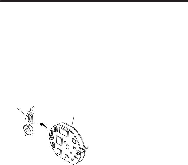
(1)In the Fieldbus communication type, the amplifier(CPU) assembly consists of two boards, as shown in Figure 2.1.
(2)In other communication types, there's the pin switch which is used for selecting the direction of hardware burnout at the position of 'SW1' on the amplifier assembly, while Fieldbus communication type does not have this pin.
(3)The Fieldbus communication type has a simulation function. A SIMULATE-ENABLE switch is mounted at 'SW1' on the amplifier. Refer to Section 6.3, “Simulation Function” for details of the simulation function.
Simulation setting switch
Amplifier Assembly
F0201.EPS
Figure 2.1 Diagram of the Amplifier Assembly
2-1 |
IM 01C50T02-01E |
3. ABOUT FIELDBUS
3.ABOUT FIELDBUS
3.1 Outline
Fieldbus is a bi-directional digital communication protocol for field devices, which offers an advancement in implementation technologies for process control systems and is widely employed by numerous field devices.
YTA Series Fieldbus communication type employs the specification standardized by The Fieldbus Foundation, and provides interoperability between Yokogawa devices and those produced by other manufacturers. Fieldbus comes with software consisting of four AI function blocks and four DI function blocks, providing the means to implement a flexible instrumentation system.
For information on other features, engineering, design, construction work, startup and maintenance of Fieldbus, refer to “Fieldbus Technical Information” (TI 38K3A01-01E).
3.2 Internal Structure of YTA
The YTA contains two virtual field devices (VFD) that share the following functions.
3.2.1 System/network Management VFD
•Sets node addresses and Phisical Device tags (PD Tag) necessary for communication.
•Controls the execution of function blocks.
•Manages operation parameters and communication resources (Virtual Communication Relationship: VCR).
3.2.2 Function Block VFD
(1)Resource block (RS)
•Manages the status of YTA hardware.
•Automatically informs the host of any detected faults or other problems.
•Outputs temperature signal.
•Carries out scaling, damping and square root extraction.
(4)DI function block
•Limit switch for temperature.
•Accepts the discrete signal from Transducer block and Outputs the discrete signal to show if the temperature exceeds the preset limit.
(5)PID function block
•Performs the PID control computation based on the deviation of the measured value from the setpoint.
3.3Logical Structure of Each Block
|
|
YTA |
System/network management VFD |
|
|
|
|
Fieldbus |
|
||
|
|
|
|
|
|
|
|
|
PD Tag |
Communication |
|
|
|
|
Node address |
parameters |
|
|
|
|
VCR |
|
|
|
|
|
|
|
|
|
|
|
|
Function block |
|
|
|
|
|
execution schedule |
|
|
|
|
Link Master (option) |
|
|
|
|
|
Function block VFD |
|
|
|
|
|
|
PID function |
|
|
|
|
|
block (option) |
|
|
|
|
|
DI function |
|
|
|
|
Transducer |
block |
|
Temperature |
Sensor |
|
AI function |
|
|
|
block |
OUT |
|
||
|
|
Sensor |
|
|
|
|
|
input |
Block tag |
Block tag |
|
|
|
|
Parameters |
Parameters |
Output |
|
|
|
Resource block |
|
|
|
|
|
Block tag |
|
|
|
|
|
Parameters |
|
|
|
|
|
|
|
F0301.EPS |
Figure 3.1 Logical Structure of Each Block
(2)Transducer block (TR)
•Accepts temperature input from sensors and transfers to AI function block.
•Operates limit swtich calculation and transfers to DI function block.
(3)AI function block
• Conditions raw data from the Transducer block.
Setting of various parameters, node addresses, and PD Tags shown in Figure 3.1 is required before starting operation.
3-1 |
IM 01C50T02-01E |
3. ABOUT FIELDBUS
3.4 Wiring System Configuration
The number of devices that can be connected to a single bus and the cable length vary depending on system design. When constructing systems, both the basic and overall design must be carefully considered to allow device performance to be fully exhibited.
3-2 |
IM 01C50T02-01E |

4. GETTING STARTED
4.GETTING STARTED
Fieldbus is fully dependent upon digital communication protocol and differs in operation from conventional 4 to 20 mA transmission and the BRAIN or HART communication protocol. It is recommended that novice users use field devices in accordance with the procedures described in this section. The procedures assume that field devices will be set up on a bench or an instrument shop.
4.1 Connection of Devices
The following instruments are required for use with Fieldbus devices:
• Power supply:
Fieldbus requires a dedicated power supply. It is recommended that current capacity be well over the total value of the maximum current consumed by all devices (including the host). Conventional DC current cannot be used as is.
• Terminator:
Fieldbus requires two terminators. Refer to the supplier for details of terminators that are attached to the host.
• Field devices:
Connect Fieldbus communication type YTA320. Two or more YTA320 devices or other devices can be connected.
• Host:
Used for accessing field devices. A dedicated host (such as DCS) is used for an instrumentation line while dedicated communication tools are used for experimental purposes. For operation of the host, refer to the instruction manual for each host. No details of the host are explained in the rest of this material.
• Cable:
Used for connecting devices. Refer to “Fieldbus Technical Information” (TI 38K3A01-01E) for details of instrumentation cabling. If the total length of the cable is in a range of 2 to 3 meters for laboratory or other experimental use, the following simplified cable (a twisted pair wire with a cross section of 0.9 mm2 or more and cycle period of within 5 cm (2 inches) may be used. Termination
processing depends on the type of device being deployed. For YTA, use an M4 screw terminal claw. Some hosts require a connector.
Refer to Yokogawa when making arrangements to purchase the recommended equipment.
Connect the devices as shown in Figure 4.1. Connect the terminators at both ends of the trunk, with a minimum length of the spur laid for connection.
The polarity of signal and power must be maintained.
Fieldbus power |
|
|
supply |
YTA320 |
HOST |
|
Terminator
Terminator
F0401.EPS
Figure 4.1 Cabling
NOTE
No CHECK terminal is used for Fieldbus communication YTA. Do not connect the field indicator and check meter. Use the instrument with the short-bar being installed between (-) terminal and the CHECK terminal.
Before using a Fieldbus configuration tool other than the existing host, confirm it does not affect the loop functionality in which all devices are already installed in operation. Disconnect the relevant control loop from the bus if necessary.
IMPORTANT
Connecting a Fieldbus configuration tool to a loop with its existing host may cause communication data scrambles resulting in a functional disorder or a system failure.
4-1 |
IM 01C50T02-01E |

4.2 Host Setting
To activate Fieldbus, the following settings are required for the host.
IMPORTANT
Do not turn off the power immediately after setting. When the parameters are saved to EEPROM, the redundant processing is executed for the improvement of reliability. If the power is turned off within 60 seconds after setting is made, the modified parameters are not saved and the settings may return to the original values.
Table 4.1 Operation Parameters
Symbol |
Parameter |
Description and Settings |
|
|
|
V (ST) |
Slot-Time |
Set 4 or greater value. |
|
|
|
V (MID) |
Minimum-Inter-PDU- |
Set 4 or greater value. |
|
Delay |
|
|
|
|
V (MRD) |
Maximum-Response- |
Set so that V (MRD) V |
|
Delay |
(ST) is 12 or greater |
|
|
|
V (FUN) |
First-Unpolled-Node |
Indicate the address next |
|
|
to the address range used |
|
|
by the host. Set 0x15 or |
|
|
greater. |
|
|
|
V (NUN) |
Number-of- |
Unused address range. |
|
consecutive- |
YTA address is factory-set |
|
Unpolled-Node |
to 0xF3. Set this address to |
|
|
be within the range of the |
|
|
BASIC device in Figure |
|
|
4.2. |
|
|
|
T0401.EPS |
|
0x00 |
|
|
|
|
Not used |
|
|
0x10 |
|
|
|
|
Bridge device |
|
|
0x14 |
LM device |
|
|
|
|
|
V(FUN) |
|
|
|
|
|
Unused |
V(NUN) |
V(FUN) V(NUN) |
|
BASIC device |
|
YTA(0xF3) |
|
|
|
0xF7 |
|
|
|
|
|
|
|
|
0xF8 |
|
|
|
|
Default address |
|
|
0xFB |
|
|
|
0xFC |
|
|
|
|
Portable device address |
|
|
0xFF |
|
|
Note 1: LM device: with bus control function (Link Master function) Note 2: BASIC device: without bus control function
F0402.EPS
Figure 4.2 Available Address Range
4. GETTING STARTED
4.3 Bus Power ON
Turn on the power of the host and the bus. Where the YTA is equipped with an LCD indicator, first all segments are lit, then the display begins to operate. If the indicator is not lit, check the polarity of the power supply.
Using the host device display function, check that the YTA is in operation on the bus.
The device information, including PD tag, Node address, and Device ID, is described on the sheet attached to YTA. The duplicates of device information are provided on this sheet.
DEVICE INFORMATION
Device ID |
: |
5945430005XXXXXXXX |
|
PD Tag |
: |
TT1001 |
|
Device Revision |
: |
2 |
|
Node Address |
: |
0xf3 |
|
Serial No. |
: |
XXXXXXXXXXXXXXXXX |
|
Physical Location |
: |
|
|
Note:
Our Device Description Files and Capabilities Files available at
http://www.yokogawa.com/fld (English) or
http://www.yokogawa.co.jp/Sensor/fieldbus/download.htm (Japanese)
F0403.EPS
Figure 4.3 Device Information Sheet Attached to YTA
If no YTA is detected, check the available address range and the polarity of the power supply. If the node address and PD tag are not specified when ordering, default value is factory set. If two or more YTAs are connected at a time with default value, one YTA will keep the address upon shipment while the other will have a default address as they have the same initial addres. Separately connect each YTA and set a different address for each.
4-2 |
IM 01C50T02-01E |

4.4 Integration of DD
If the host supports DD (Device Description), the DD of the YTA needs to be installed. Check if host has the following directory under its default DD directory.
594543\0005
(594543 is the manufacturer number of Yokogawa Electric Corporation, and 0005 is the YTA device number, respectively.)
If this directory is not found, DD of YTA has not been included. Create the above directory and copy the DD file (0m0n.ffo,0m0n.sym) (m, n is a numeral) into the directory. If you do not have the DD or capabilities files, you can download them from our web site. Visit the following web site.
http://www.yokogawa.com/fld
Once the DD is installed in the directory, the name and attribute of all parameters of the YTA are displayed.
Off-line configuration is possible by using capabilities files.
NOTE
Ensure to use the suitable file for the device. YTA has three types, one with the standard function blocks, one with /LC1(additional PID and LAS function) and one with /LC2(additional 2 PIDs and LAS function). If the different type capabilities file is used, some errors may occur at downloading to the device.
4.5 Reading the Parameters
To read YTA parameters, select the AI1 block of the YTA from the host screen and read the OUT parameter. The current temperature which is assign to AI1 block is displayed. Sensor 1 input is assigned to AI1 block upon shipment. Check that actual of MODE_BLOCK of the function block and resource block is set to Auto, and increase the temperature measured by Sensor1 and read the parameter again. A new designated value should be displayed.
4. GETTING STARTED
4.6 Continuous Record of Values
If the host has a function of continuously recording the indications, use this function to list the indications (values). Depending on the host being used, it may be necessary to set the schedule of Publish (the function that transmits the indication on a periodic basis).
4.7 Generation of Alarm
If the host is allowed to receive alarms, generation of an alarm can be attempted from YTA. In this case, set the reception of alarms on the host side. YTA’s VCR-6 is factory-set for this purpose. For practical purposes, all alarms are placed in a disabled status; for this reason, it is recommended that you first use one of these alarms on a trial basis. Set the value of link object-3 (index 30002) as “0, 298, 0, 6, 0”. Refer to section 5.6.1 Link Object for details.
Since the LO_PRI parameter (index 4029) of the AI1 block is set to “0”, try setting this value to “3”. Select the Write function from the host in operation, specify an index or variable name, and write “3” to it.
The LO_LIM parameter (index 4030) of the AI1 block determines the limit at which the lower bound alarm for the process value is given. In usual cases, a very small value is set to this limit. Set the value which is apparantely higher than expected measured value to the limit. For example, in case masuering room temperature of 28 C, SET '50( C)' to the limit. Since the measured temperature is lower than the limit, lower bound alarm is raised. Check that the alarm can be received at the host. When the alarm is confirmed, transmission of the alarm is suspended.
The above-mentioned items are a description of the simple procedure to be carried out until YTA is connected to Fieldbus. In order to take full advantage of the performance and functionality of the device, it is recommended that it be read together with Chapter 5, which describes how to use the YTA.
4-3 |
IM 01C50T02-01E |

5. CONFIGURATION
5.CONFIGURATION
This chapter contains information on how to adapt the function and performance of the YTA to suit specific applications. Because two or more devices are connected to Fieldbus, settings including the requirements of all devices need to be determined. Practically, the following steps must be taken.
(1)Network design
Determines the devices to be connected to Fieldbus and checks the capacity of the power supply.
(2)Network definition
Determines the tag and node addresses for all devices.
(3)Definition of combining function blocks
Determines the method for combination between each function block.
(4)Setting tags and addresses
Sets the PD Tag and node addresses one by one for each device.
(5)Communication setting
Sets the link between communication parameters and function blocks.
(6)Block setting
Sets the parameters for function blocks.
The following section describes each step of the procedure in the order given. Using a dedicated configuration tool allows the procedure to be significantly simplified. This section describes the procedure to be assigned for a host which has relatively simple functions. Refer to Appendix 5 when the YTA is used as Link Master.
5.1 Network Design
Select the devices to be connected to the Fieldbus network. The following instruments are necessary for operation of Fieldbus.
• Power supply
Fieldbus requires a dedicated power supply. It is recommended that current capacity be well over the total value of the maximum current consumed by all devices (including the host). Conventional DC current cannot be used as is.
• Terminator
Fieldbus requires two terminators. Refer to the supplier for details of terminators that are attached to the host.
• Field devices
Connect the field devices necessary for instrumentation. YTA has passed the interoperability test conducted by The Fieldbus Foundation. In order to properly start Fieldbus, it is recommended that the devices used satisfy the requirements of the above test.
• Host
Used for accessing field devices. A minimum of one device with bus control function is needed.
• Cable
Used for connecting devices. Refer to “Fieldbus Technical Information” for details of instrumentation cabling. Provide a cable sufficiently long to connect all devices. For field branch cabling, use terminal boards or a connection box as required.
First, check the capacity of the power supply. The power supply capacity must be greater than the sum of the maximum current consumed by all devices to be connected to Fieldbus. The maximum current consumed (power supply voltage 9 V to 32 V) for YTA is 16.6 mA. The cable must have the spur in a minimum length with terminators installed at both ends of the trunk.
5.2 Network Definition
Before connection of devices with Fieldbus, define the Fieldbus network. Allocate PD Tag and node addresses to all devices (excluding such passive devices as terminators).
The PD Tag is the same as the conventional one used for the device. Up to 32 alphanumeric characters may be used for definition. Use a hyphen as a delimiter as required.
The node address is used to specify devices for communication purposes. Because data is too long for a PD Tag, the host uses the node address in place of the PD Tag for communication. A range of 16 to 247
5-1 |
IM 01C50T02-01E |
(or hexadecimal 10 to F7) can be set. The device (LM device) with bus control function (Link Master function) is allocated from a smaller address number (16) side, and other devices (BASIC device) without bus control function allocated from a larger address number (247) side respectively. Place YTA in the range of the BASIC device. When the YTA is used as Link Master, place YTA in the range of LM device. Set the range of addresses to be used to the LM device. Set the following parameters.
Table 5.1 Parameters for Setting Address Range
Symbol |
Parameters |
Description |
|
|
|
V (FUN) |
First-Unpolled-Node |
Indicates the address next |
|
|
to the address range used |
|
|
for the host or other LM |
|
|
device. |
|
|
|
V (NUN) |
Number-of- |
Unused address range |
|
consecutive- |
|
|
Unpolled-Node |
|
|
|
|
|
|
T0501.EPS |
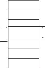
The devices within the address range written as “Unused” in Figure 5.1 cannot be used on a Fieldbus. For other address ranges, the range is periodically checked to identify when a new device is mounted. Care must be taken not to allow the address range to become wider, which can lead to exhaustive consumption of Fieldbus communication performance.
0x00 |
|
|
|
Not used |
|
0x10 |
|
|
|
Bridge device |
|
0x14 |
LM device |
|
|
|
|
V(FUN) |
|
|
|
Unused |
V(NUN) |
V(FUN) V(NUN) |
BASIC device |
|
|
|
|
0xF7 |
|
|
0xF8 |
|
|
|
Default address |
|
0xFB |
|
|
0xFC |
|
|
|
Portable device address |
|
0xFF |
|
|
|
|
F0501.EPS |
Figure 5.1 Available Range of Node Addresses
To ensure stable operation of Fieldbus, determine the operation parameters and set them to the LM devices. While the parameters in Table 5.2 are to be set, the worst-case value of all the devices to be connected to the same Fieldbus must be used. Refer to the specification of each device for details. Table 5.2 lists YTA specification values.
5. CONFIGURATION
Table 5.2 Operation Parameter Values of the YTA to be Set to LM Devices
Symbol |
Parameters |
Description and Settings |
|
|
|
V (ST) |
Slot-Time |
Indicates the time |
|
|
necessary for immediate |
|
|
reply of thje device. Unit of |
|
|
time is in octets (256 s). |
|
|
Set maximum specification |
|
|
for all devices. For YTA, |
|
|
set a value of 4 or greater. |
|
|
|
V (MID) |
Minimum-Inter-PDU- |
Minimum value of |
|
Delay |
communication data |
|
intervals. Unit of time is in |
|
|
|
|
|
|
octets (256 s). Set the |
|
|
maximum specification for |
|
|
all devices. For YTA, set a |
|
|
value of 4 or greater. |
|
|
|
V (MRD) |
Maximum-Reply-Delay |
The worst case time |
|
|
elapsed until a reply is |
|
|
recorded. The unit is Slot- |
|
|
time; set the value so that |
|
|
V (MRD) V (ST) is the |
|
|
maximum value of the |
|
|
specification for all |
|
|
devices. For YTA, the |
|
|
setting must be a value of |
|
|
12 or greater. |
|
|
|
|
|
T0502.EPS |
5.3Definition of Combining Function Blocks
The input/output parameters for function blocks are combined. For the YTA, four AI blocks output parameter (OUT), four DI blocks output parameter (OUT_D) and PID block are subject to combination. They are combined with the input of the control block as necessary. Practically, setting is written to the YTA link object with reference to “Block setting” in Section 5.6 for details. It is also possible to read values from the host at proper intervals instead of connecting the YTA block output to other blocks.
The combined blocks need to be executed synchronously with other blocks on the communications schedule. In this case, change the YTA schedule according to the following table. Enclosed values in the table are factory-settings.
Table 5.3 Execution Schedule of the YTA Function Blocks
Index |
|
Parameters |
Setting (Enclosed is |
|
|
factory-setting) |
|||
|
|
|
||
269 |
MACROCYCLE_ |
Cycle (MACROCYCLE) |
||
(SM) |
DURATION |
period of control or |
||
measurement. Unit is 1/32 |
||||
|
|
|
||
|
|
|
ms. (16000 = 0.5 s) |
|
|
|
|
||
276 |
FB_START_ENTRY.1 |
AI1 block startup time. |
||
(SM) |
|
|
Elapsed time from the start |
|
|
|
of MACROCYCLE specified |
||
|
|
|
||
|
|
|
in 1/32 ms. (0 = 0 s) |
|
|
|
|
||
277 |
FB_START_ENTRY.2 |
AI2 block startup time. |
||
(SM) |
|
|
Elapsed time from the start |
|
|
|
|
of MACROCYCLE specified |
|
|
|
|
in 1/32 ms. (4000 = 125ms) |
|
278 |
FB_START_ENTRY.3 |
|
||
to |
to |
|
Not used. |
|
285 |
FB_START_ENTRY.10 |
|||
|
|
|
||
(SM) |
|
|
|
|
|
|
|
|
|
|
|
|
T0503.EPS |
|
5-2 |
IM 01C50T02-01E |

A maximum of 50 ms is taken for execution of each AI block. A maximum of 30 ms is taken for execution of each DI block, and 100ms for each PID block. For scheduling of communications for combination with the next function block, the execution is so arranged as to start after a lapse of longer than 100 ms. In no case should function blocks of the YTA be executed at the same time (execution time is overlapped).
Figure 5.3 shows an example of schedule based on the loop shown in Figure 5.2.
|
TIC100 |
|
YTA |
TC200 |
|
#1 |
||
|
||
|
TT100 |
YTA #2
TT 200
TV200
F0502.EPS
Figure 5.2 Example of Loop Connecting Function Block of Two YTA with Other Instruments
Macrocycle (Control Period)
|
TT100 |
IN |
|
|
|
|
OUT |
CAS_IN |
|
||
|
|
|
|||
Function |
|
TIC100 |
BKCAL_OUT |
||
|
|
||||
|
|
|
|||
Block |
BKCAL_IN |
TC200 |
TV200 |
||
Schedule |
|||||
|
|
||||
|
|
|
|
||
|
TT200 |
IN |
|
||
|
BKCAL_IN BKCAL_OUT |
||||
|
|
OUT |
|||
Commu- |
Unscheduled |
nication |
Communication |
Schedule
Scheduled
Communication
F0503.EPS
Figure 5.3 Function Block Schedule and Communication
Schedule
When the control period (macrocycle) is set to more than 4 seconds, set the following interval to be more than 1% of the control period.
-Interval between “end of block execution” and “start of sending CD from LAS”
-Interval between “end of block execution” and “start of the next block execution”
5. CONFIGURATION
5.4Setting of Tags and Addresses
This section describes the steps in the procedure to set PD Tags and node addresses in the YTA. There are three states of Fieldbus devices as shown in Figure 5.4, and if the state is other than the lowest SM_OPERATIONAL state, no function block is executed. YTA must be transferred to this state when an YTA tag or address is changed.
UNINITIALIZED
(No tag nor address is set)
Tag clear |
|
Tag setting |
|
||
|
|
|
|
|
|
INITIALIZED (Only tag is set)
|
|
|
|
Address clear |
|
Address setting |
|
|
|||
|
|
|
|
|
|
|
|
SM_OPERATIONAL
(Tag and address are retained, and the function block can be executed.)
F0504.EPS
Figure 5.4 Status Transition by Setting PD Tag and Node Address
YTA has a PD Tag (TT1001) and node address (243, or hexadecimal 0xF3) that are set upon shipment from the factory unless otherwise specified. To change only the node address, clear the address once and then set a new node address. To set the PD Tag, first clear the node address and clear the PD Tag, then set the PD Tag and node address again.
Devices whose node address was cleared will await the default address (randomly chosen from a range of 248 to 251, or from hexadecimal F8 to FB). At the same time, it is necessary to specify the device ID in order to correctly specify the device. The device ID of the YTA is 5945430005xxxxxxxx. (The xxxxxxxx at the end of the above device ID is a total of 8 alphanumeric characters.)
5-3 |
IM 01C50T02-01E |
5.5 Communication Setting
To set the communication function, it is necessary to change the database residing in SM-VFD.
5.5.1 VCR Setting
Set VCR (Virtual Communication Relationship), which specifies the called party for communication and resources. YTA has 30 VCRs whose application can be changed, except for the first VCR, which is used for management.
YTA has VCRs of four types:
Server(QUB) VCR
A Server responds to requests from a host. This communication needs data exchange. This type of communication is called QUB (Queued Usertriggered Bidirectional) VCR.
Source (QUU) VCR
A Source multicasts alarms or trends to other devices. This type of communication is called QUU (Queued User-triggered Unidirectional) VCR.
Publisher (BNU) VCR
A Publisher multicasts AI block and DI block output to another function block(s). This type of communication is called BNU (Buffered Network-triggered Unidirectional) VCR.
Subscriber (BNU) VCR
A Subscriber receives output of another function block(s) by PID block.
A Server VCR is capable to respond to requests from a Client (QUB) VCR after the Client initiates connection to the Server successfully. A Source VCR transmits data without established connection. A Sink (QUU) VCR on another device can receive it if the Sink is configured so. A Publisher VCR transmits data when LAS requests so. An explicit connection is established from Subscriber (BNU) VCR(s) so that a Subscriber knows the format of published data.
Each VCR has the parameters listed in Table 5.4. Parameters must be changed together for each VCR because modification for each parameter may cause inconsistent operation.
|
|
|
5. CONFIGURATION |
Table 5.4 VCR Static Entry |
|
||
|
|
|
|
|
Sub- |
Parameter |
Description |
|
index |
||
|
|
|
|
|
1 |
FasArTypeAndRole |
Indicates the type and role of |
|
|
|
communication (VCR). The |
|
|
|
following 4 types are used |
|
|
|
for YTA. |
|
|
|
0x32: Server (Responds to |
|
|
|
requests from host.) |
|
|
|
0x44: Source (Transmits |
|
|
|
alarm or trend.) |
|
|
|
0x66: Publisher (Sends AI |
|
|
|
block output to other |
|
|
|
blocks.) |
|
|
|
0x76: Subscriber (Receives |
|
|
|
output of other blocks |
|
|
|
by PID block.) |
|
|
|
|
|
2 |
FasDllLocalAddr |
Sets the local address to |
|
|
|
specify VCR in YTA. A range |
|
|
|
of 20 to F7 in hexadecimal. |
|
3 |
FasDllConfigured |
Sets the node address of the |
|
|
RemoteAddr |
called party for |
|
|
|
communication and the |
|
|
|
address (DLSAP or DLCEP) |
|
|
|
used to specify VCR in that |
|
|
|
address. For DLSAP or |
|
|
|
DLCEP, a range of 20 to F7 |
|
|
|
in hexadecimal is used. |
|
|
|
Addresses in Subindex 2 |
|
|
|
and 3 need to be set to the |
|
|
|
same contents of the VCR |
|
|
|
as the called party (local and |
|
|
|
remote are reversed). |
|
|
|
|
|
4 |
FasDllSDAP |
Specifies the quality of |
|
|
|
communication. Usually, one |
|
|
|
of the following types is set. |
|
|
|
0x2B: Server |
|
|
|
0x01: Source (Alert) |
|
|
|
0x03: Source (Trend) |
|
|
|
0x91: Publisher/Subscriber |
|
5 |
FasDllMaxConfirm |
To establish connection for |
|
|
DelayOnConnect |
communication, a maximum |
|
|
|
wait time for the called |
|
|
|
party's response is set in |
|
|
|
ms. Typical value is 60 |
|
|
|
seconds (60000). |
|
|
|
|
|
6 |
FasDllMaxConfirm |
For request of data, a |
|
|
DelayOnData |
maximum wait time for the |
|
|
|
called party's response is |
|
|
|
set in ms. Typical value is |
|
|
|
60 seconds (60000). |
|
|
|
|
|
7 |
FasDllMaxDlsduSize |
Specifies maximum DL |
|
|
|
Service Data unit Size |
|
|
|
(DLSDU). Set 256 for Server |
|
|
|
and Trend VCR, and 64 for |
|
|
|
other VCRs. |
|
|
|
|
|
8 |
FasDllResidual |
Specifies whether |
|
|
ActivitySupported |
connection is monitored. Set |
|
|
|
TRUE (0xff) for Server. This |
|
|
|
parameter is not used for |
|
|
|
other communication. |
|
9 |
FasDllTimelinessClass |
Not used for YTA. |
|
|
|
|
|
10 |
FasDllPublisherTime |
Not used for YTA. |
|
|
WindowSize |
|
|
|
|
|
|
11 |
FasDllPublisher |
Not used for YTA. |
|
|
SynchronizaingDlcep |
|
|
|
|
|
|
|
|
T0504-1.EPS |
5-4 |
IM 01C50T02-01E |

Sub- |
Parameter |
Description |
|
index |
|||
|
|
||
12 |
FasDllSubsriberTime |
Not used for YTA. |
|
|
WindowSize |
|
|
|
|
|
|
13 |
FasDllSubscriber |
Not used for YTA. |
|
|
SynchronizationDlcep |
|
|
|
|
|
|
14 |
FmsVfdId |
Sets VFD for YTA to be |
|
|
|
used. |
|
|
|
0x1: System/network |
|
|
|
management VFD |
|
|
|
0x1234: Function block |
|
|
|
VFD |
|
|
|
|
|
15 |
FmsMaxOutstanding |
Set 0 to Server. It is not |
|
|
ServiceCalling |
used for other applications. |
|
|
|
|
|
16 |
FmsMaxOutstanding |
Set 1 to Server. It is not |
|
|
ServiceCalled |
used for other applications. |
|
|
|
|
|
17 |
FmsFeatures |
Indicates the type of |
|
|
Supported |
services in the application |
|
|
|
layer. In the YTA, it is |
|
|
|
automatically set according |
|
|
|
to specific applications. |
|
|
|
T0504-2.EPS |
30 VCRs are factory-set as shown in the table below.
Table 5.5 |
VCR List |
|
||
|
|
|
|
|
|
Index |
VCR |
|
Factory Setting |
|
(SM) |
Number |
|
|
|
|
|
||
|
|
|
|
|
|
293 |
1 |
|
For system management (Fixed) |
|
|
|
|
|
|
294 |
2 |
|
Server (LocalAddr = 0xF3) |
|
|
|
|
|
|
295 |
3 |
|
Server (LocalAddr = 0xF4) |
|
|
|
|
|
|
296 |
4 |
|
Server (LocalAddr = 0xF7) |
|
|
|
|
|
|
297 |
5 |
|
Trend Source (LocalAddr = 0x07, |
|
|
|
|
Remote Address=0x111) |
|
298 |
6 |
|
Alert Source (LocalAddr = 0x07, |
|
|
|
|
Remote Address=0x110) |
|
|
|
|
|
|
299 |
7 to 30 |
|
Not used. |
|
to |
|
||
|
322 |
|
|
|
|
|
|
|
T0505.EPS |
5.5.2 Function Block Execution Control
According to the instructions given in Section 5.3, set the execution cycle of the function blocks and schedule of execution.
5.6 Block Setting
Set the parameter for function block VFD.
5.6.1 Link Object
Link object combines the data voluntarily sent by the function block with VCR. YTA has 26 link objects. A single link object specifies one combination. Each link object has the parameters listed in Table 5.6.
5. CONFIGURATION
Parameters must be changed together for each VCR because the modifications made to each parameter may cause inconsistent operation.
Table 5.6 Link Object Parameters
Sub- |
Parameters |
Description |
|
index |
|||
|
|
||
|
|
|
|
1 |
LocalIndex |
Sets the index of function |
|
|
|
block parameters to be |
|
|
|
combined; set “0” for Trend |
|
|
|
and Alert. |
|
2 |
VcrNumber |
Sets the index of VCR to |
|
|
|
be combined. If set to “0”, |
|
|
|
this link object is not used. |
|
|
|
|
|
3 |
RemoteIndex |
Not used in YTA.Set to “0”. |
|
4 |
ServiceOperation |
Set one of the following. |
|
|
|
Set only one each for link |
|
|
|
object for Alert or Trend. |
|
|
|
0: Undefined |
|
|
|
2: Publisher |
|
|
|
3: Subscriber |
|
|
|
6: Alert |
|
|
|
7: Trend |
|
|
|
|
|
5 |
StaleCountLimit |
Set the maximum number |
|
|
|
of consecutive stale input |
|
|
|
values which may be |
|
|
|
received before the input |
|
|
|
status is set to BAD. To |
|
|
|
avoid the unnecessary |
|
|
|
mode transition caused |
|
|
|
when the data is not |
|
|
|
correctly received by |
|
|
|
subscriber, set this |
|
|
|
parameter to “2” or more. |
|
|
|
|
|
|
|
T0506.EPS |
26 Link objects are not factory-set.
5.6.2 Trend Object
It is possible to set the parameter so that the function block automatically transmits Trend. YTA has ten Trend objects, six of which are used for Trend in analog mode parameters and four is used for Trend in discrete mode parameter. A single Trend object specifies the trend of one parameter.
Each Trend object has the parameters listed in Table 5.8. The first four parameters are the items to be set.
5-5 |
IM 01C50T02-01E |
Table 5.8 Parameters for Trend Objects
Sub- |
Parameters |
Description |
|
index |
|||
|
|
||
|
|
|
|
1 |
Block Index |
Sets the leading index of |
|
|
|
the function block that |
|
|
|
takes a trend. |
|
2 |
Parameter Relative |
Sets the index of |
|
|
Index |
parameters taking a trend |
|
|
|
by a value relative to the |
|
|
|
beginning of the function |
|
|
|
block. |
|
3 |
Sample Type |
Specifies how trends are |
|
|
|
taken. Choose one of the |
|
|
|
following 2 types: |
|
|
|
1: Sampled upon |
|
|
|
execution of a function |
|
|
|
block. |
|
|
|
2: The average value is |
|
|
|
sampled. |
|
|
|
|
|
4 |
Sample Interval |
Specifies sampling |
|
|
|
intervals in units of 1/32 |
|
|
|
ms. Set the integer |
|
|
|
multiple of the function |
|
|
|
block execution cycle. |
|
|
|
|
|
5 |
Last Update |
The last sampling time. |
|
|
|
|
|
6 to 21 |
List of Status |
Status part of a sampled |
|
|
|
parameter. |
|
|
|
|
|
21 to 37 |
List of Samples |
Data part of a sampled |
|
|
|
parameter. |
|
|
|
|
|
|
|
T0508.EPS |
Five trend objects are factory-set as shown Table 5.9.
Table 5.9 Trend Object are Factory-Set
Index |
Parameters |
Factory Settings |
|
|
|
32000 |
TREND_FLT.1 |
Not used. |
to |
to |
|
32005 |
TREND_FLT.6 |
|
|
|
|
32006 |
TREND_DIS.1 |
Not used. |
to |
to |
|
32010 |
TREND_DIS.4 |
|
|
|
|
T0509.EPS
5. CONFIGURATION
5.6.3 View Object
This is the object to form groups of parameters in a block. One of advantage brought by forming groups of parameters is the reduction of load for data transaction. YTA has four View Objects for each Resource block, Transducer block and each function block, and each View Object has the parameters listed in Table 5.11 to 5.13.
Table 5.10 Purpose of Each View Object
Description
VIEW_1 Set of dynamic parameters required by operator for plant operation. (PV, SV, OUT, Mode etc.)
VIEW_2 Set of static parameters which need to be shown to plant operator at once. (Range etc.)
VIEW_3 Set of all the dynamic parameters.
VIEW_4 Set of static parameters for configuration or maintenance.
T0510.EPS
5-6 |
IM 01C50T02-01E |
5. CONFIGURATION
Table 5.11 View Object for Resource Block
Relative |
Parameter |
VIEW |
VIEW |
VIEW |
VIEW |
index |
|
1 |
2 |
3 |
4 |
1 |
ST_REV |
2 |
2 |
2 |
2 |
|
|
|
|
|
|
2 |
TAG_DESC |
|
|
|
|
|
|
|
|
|
|
3 |
STRATEGY |
|
|
|
2 |
|
|
|
|
|
|
4 |
ALERT_KEY |
|
|
|
1 |
|
|
|
|
|
|
5 |
MODE_BLK |
4 |
|
4 |
|
|
|
|
|
|
|
6 |
BLOCK_ERR |
2 |
|
2 |
|
|
|
|
|
|
|
7 |
RS_STATE |
1 |
|
1 |
|
|
|
|
|
|
|
8 |
TEST_RW |
|
|
|
|
|
|
|
|
|
|
9 |
DD_RESOURCE |
|
|
|
|
|
|
|
|
|
|
10 |
MANUFAC_ID |
|
|
|
4 |
|
|
|
|
|
|
11 |
DEV_TYPE |
|
|
|
2 |
|
|
|
|
|
|
12 |
DEV_REV |
|
|
|
1 |
|
|
|
|
|
|
13 |
DD_REV |
|
|
|
1 |
|
|
|
|
|
|
14 |
GRANT_DENY |
|
2 |
|
|
|
|
|
|
|
|
15 |
HARD_TYPES |
|
|
|
2 |
|
|
|
|
|
|
16 |
RESTART |
|
|
|
|
|
|
|
|
|
|
17 |
FEATURES |
|
|
|
2 |
|
|
|
|
|
|
18 |
FEATURE_SEL |
|
2 |
|
|
|
|
|
|
|
|
19 |
CYCLE_TYPE |
|
|
|
2 |
|
|
|
|
|
|
20 |
CYCLE_SEL |
|
2 |
|
|
|
|
|
|
|
|
21 |
MIN_CYCLE_T |
|
|
|
4 |
|
|
|
|
|
|
22 |
MEMORY_SIZE |
|
|
|
2 |
|
|
|
|
|
|
23 |
NV_CYCLE_T |
|
4 |
|
|
|
|
|
|
|
|
24 |
FREE_SPACE |
|
4 |
|
|
|
|
|
|
|
|
25 |
FREE_TIME |
4 |
|
4 |
|
|
|
|
|
|
|
26 |
SHED_RCAS |
|
4 |
|
|
|
|
|
|
|
|
27 |
SHED_ROUT |
|
4 |
|
|
|
|
|
|
|
|
28 |
FAULT_STATE |
1 |
|
1 |
|
|
|
|
|
|
|
29 |
SET_FSTATE |
|
|
|
|
|
|
|
|
|
|
30 |
CLR_FSTATE |
|
|
|
|
|
|
|
|
|
|
31 |
MAX_NOTIFY |
|
|
|
1 |
|
|
|
|
|
|
32 |
LIM_NOTIFY |
|
1 |
|
|
|
|
|
|
|
|
33 |
CONFIRM_TIME |
|
4 |
|
|
|
|
|
|
|
|
34 |
WRITE_LOCK |
|
1 |
|
|
|
|
|
|
|
|
35 |
UPDATE_EVT |
|
|
|
|
|
|
|
|
|
|
36 |
BLOCK_ALM |
|
|
|
|
|
|
|
|
|
|
37 |
ALARM_SUM |
8 |
|
8 |
|
|
|
|
|
|
|
38 |
ACK_OPTION |
|
|
|
2 |
|
|
|
|
|
|
39 |
WRITE_PRI |
|
|
|
1 |
|
|
|
|
|
|
40 |
WRITE_ALM |
|
|
|
|
|
|
|
|
|
|
41 |
ITK_VER |
|
|
|
2 |
|
|
|
|
|
|
42 |
SOFT_REV |
|
|
|
|
|
|
|
|
|
|
43 |
SOFT_DESC |
|
|
|
|
|
|
|
|
|
|
44 |
SIM_ENABLE_MSG |
|
|
|
|
|
|
|
|
|
|
Relative |
Parameter |
VIEW |
VIEW |
VIEW |
VIEW |
index |
|
1 |
2 |
3 |
4 |
45 |
DEVICE_STATUS_1 |
|
|
4 |
|
|
|
|
|
|
|
46 |
DEVICE_STATUS_2 |
|
|
4 |
|
|
|
|
|
|
|
47 |
DEVICE_STATUS_3 |
|
|
4 |
|
|
|
|
|
|
|
48 |
DEVICE_STATUS_4 |
|
|
4 |
|
|
|
|
|
|
|
49 |
DEVICE_STATUS_5 |
|
|
4 |
|
|
|
|
|
|
|
50 |
DEVICE_STATUS_6 |
|
|
4 |
|
|
|
|
|
|
|
51 |
DEVICE_STATUS_7 |
|
|
4 |
|
|
|
|
|
|
|
52 |
DEVICE_STATUS_8 |
|
|
4 |
|
|
|
|
|
|
|
|
Total in byte |
22 |
30 |
54 |
31 |
|
|
|
|
|
|
T0511.EPS
5-7 |
IM 01C50T02-01E |
5. CONFIGURATION
Table 5.12 View Object for Transducer Block
Relative |
Parameter |
VIEW |
VIEW |
VIEW |
VIEW |
VIEW |
VIEW |
VIEW |
VIEW |
index |
1 |
2 |
3 |
4 |
4 |
4 |
4 |
4 |
|
|
(1st) |
(2nd) |
(3rd) |
(4th) |
(5th) |
||||
|
|
|
|
|
|||||
1 |
ST_REV |
2 |
2 |
2 |
2 |
2 |
2 |
2 |
2 |
|
|
|
|
|
|
|
|
|
|
2 |
TAG_DESC |
|
|
|
|
|
|
|
|
|
|
|
|
|
|
|
|
|
|
3 |
STRATEGY |
|
|
|
2 |
|
|
|
|
|
|
|
|
|
|
|
|
|
|
4 |
ALERT_KEY |
|
|
|
1 |
|
|
|
|
|
|
|
|
|
|
|
|
|
|
5 |
MODE_BLK |
4 |
|
4 |
|
|
|
|
|
|
|
|
|
|
|
|
|
|
|
6 |
BLOCK_ERR |
2 |
|
2 |
|
|
|
|
|
|
|
|
|
|
|
|
|
|
|
7 |
UPDATE_EVT |
|
|
|
|
|
|
|
|
|
|
|
|
|
|
|
|
|
|
8 |
BLOCK_ALM |
|
|
|
|
|
|
|
|
|
|
|
|
|
|
|
|
|
|
9 |
TRANSDUCER_DIRECTORY |
|
|
|
|
|
|
|
|
|
|
|
|
|
|
|
|
|
|
10 |
TRANSDUCER_TYPE |
2 |
2 |
2 |
2 |
|
|
|
|
|
|
|
|
|
|
|
|
|
|
11 |
XD_ERROR |
1 |
|
1 |
|
|
|
|
|
|
|
|
|
|
|
|
|
|
|
12 |
COLLECTION_DIRECTORY |
|
|
|
|
|
|
|
|
|
|
|
|
|
|
|
|
|
|
13 |
PRIMARY_VALUE_TYPE_1 |
|
2 |
|
|
|
|
|
|
|
|
|
|
|
|
|
|
|
|
14 |
PRIMARY_VALUE_1 |
5 |
|
5 |
|
|
|
|
|
|
|
|
|
|
|
|
|
|
|
15 |
PRIMARY_VALUE_RANGE_1 |
|
|
|
|
11 |
|
|
|
|
|
|
|
|
|
|
|
|
|
16 |
CAL_POINT_HI_1 |
|
4 |
|
|
|
|
|
|
|
|
|
|
|
|
|
|
|
|
17 |
CAL_POINT_LO_1 |
|
4 |
|
|
|
|
|
|
|
|
|
|
|
|
|
|
|
|
18 |
CAL_MIN_SPAN_1 |
|
|
|
|
4 |
|
|
|
|
|
|
|
|
|
|
|
|
|
19 |
CAL_UNIT_1 |
|
|
|
|
2 |
|
|
|
|
|
|
|
|
|
|
|
|
|
20 |
SENSOR_TYPE_1 |
|
|
|
|
2 |
|
|
|
|
|
|
|
|
|
|
|
|
|
21 |
SENSOR_RANGE_1 |
|
|
|
|
11 |
|
|
|
|
|
|
|
|
|
|
|
|
|
22 |
SENSOR_SN_1 |
|
|
|
|
32 |
|
|
|
|
|
|
|
|
|
|
|
|
|
23 |
SENSOR_CAL_METHOD_1 |
|
|
|
|
|
1 |
|
|
|
|
|
|
|
|
|
|
|
|
24 |
SENSOR_CAL_LOC_1 |
|
|
|
|
|
32 |
|
|
|
|
|
|
|
|
|
|
|
|
25 |
SENSOR_CAL_DATE_1 |
|
|
|
|
|
6 |
|
|
|
|
|
|
|
|
|
|
|
|
26 |
SENSOR_CAL_WHO_1 |
|
|
|
|
|
32 |
|
|
|
|
|
|
|
|
|
|
|
|
27 |
SENSOR_CONNECTION_1 |
|
|
|
|
2 |
|
|
|
|
|
|
|
|
|
|
|
|
|
28 |
PRIMARY_VALUE_TYPE_2 |
|
2 |
|
|
|
|
|
|
|
|
|
|
|
|
|
|
|
|
29 |
PRIMARY_VALUE_2 |
5 |
|
5 |
|
|
|
|
|
|
|
|
|
|
|
|
|
|
|
30 |
PRIMARY_VALUE_RANGE_2 |
|
|
|
|
|
|
11 |
|
|
|
|
|
|
|
|
|
|
|
31 |
CAL_POINT_HI_2 |
|
4 |
|
|
|
|
|
|
|
|
|
|
|
|
|
|
|
|
32 |
CAL_POINT_LO_2 |
|
4 |
|
|
|
|
|
|
|
|
|
|
|
|
|
|
|
|
33 |
CAL_MIN_SPAN_2 |
|
|
|
|
|
|
4 |
|
|
|
|
|
|
|
|
|
|
|
34 |
CAL_UNIT_2 |
|
|
|
|
|
|
2 |
|
|
|
|
|
|
|
|
|
|
|
35 |
SENSOR_TYPE_2 |
|
|
|
|
|
|
2 |
|
|
|
|
|
|
|
|
|
|
|
36 |
SENSOR_RANGE_2 |
|
|
|
|
|
|
11 |
|
|
|
|
|
|
|
|
|
|
|
37 |
SENSOR_SN_2 |
|
|
|
|
|
|
32 |
|
|
|
|
|
|
|
|
|
|
|
38 |
SENSOR_CAL_METHOD_2 |
|
|
|
|
|
|
|
1 |
|
|
|
|
|
|
|
|
|
|
39 |
SENSOR_CAL_LOC_2 |
|
|
|
|
|
|
|
32 |
|
|
|
|
|
|
|
|
|
|
40 |
SENSOR_CAL_DATE_2 |
|
|
|
|
|
|
|
6 |
|
|
|
|
|
|
|
|
|
|
41 |
SENSOR_CAL_WHO_2 |
|
|
|
|
|
|
|
32 |
|
|
|
|
|
|
|
|
|
|
42 |
SENSOR_CONNECTION_2 |
|
|
|
|
|
|
2 |
|
|
|
|
|
|
|
|
|
|
|
43 |
SECONDARY_VALUE |
|
|
5 |
|
|
|
|
|
|
|
|
|
|
|
|
|
|
|
44 |
SECONDARY_VALUE_UNIT |
|
|
|
2 |
|
|
|
|
|
|
|
|
|
|
|
|
|
|
45 |
MODULE_SN |
|
|
|
32 |
|
|
|
|
|
|
|
|
|
|
|
|
|
|
T0512-1.EPS
5-8 |
IM 01C50T02-01E |

5. CONFIGURATION
Relative |
Parameter |
VIEW |
VIEW VIEW |
VIEW VIEW VIEW VIEW VIEW |
|||||
index |
1 |
2 |
3 |
4 |
4 |
4 |
4 |
4 |
|
|
(1st) |
(2nd) |
(3rd) |
(4th) |
(5th) |
||||
|
|
|
|
|
|||||
46 |
ALARM_SUM |
|
|
8 |
|
|
|
|
|
|
|
|
|
|
|
|
|
|
|
47 |
PRIMARY_VALUE_FTIME_1 |
|
4 |
|
|
|
|
|
|
|
|
|
|
|
|
|
|
|
|
48 |
CAL_STATE_1 |
|
|
|
|
1 |
|
|
|
|
|
|
|
|
|
|
|
|
|
49 |
CJC_SELECT_1 |
|
|
|
|
1 |
|
|
|
|
|
|
|
|
|
|
|
|
|
50 |
CONSTANT_CJC_TEMP_1 |
|
|
|
|
4 |
|
|
|
|
|
|
|
|
|
|
|
|
|
51 |
WIRING_RESISTANCE_1 |
|
|
|
|
4 |
|
|
|
|
|
|
|
|
|
|
|
|
|
52 |
SENSOR_MATCH_R0_1 |
|
|
|
|
|
|
|
|
|
|
|
|
|
|
|
|
|
|
53 |
SENSOR_MATCH_A_1 |
|
|
|
|
|
|
|
|
|
|
|
|
|
|
|
|
|
|
54 |
SENSOR_MATCH_B_1 |
|
|
|
|
|
|
|
|
55SENSOR_MATCH_C_1
56SENSOR_MATCH_ALPHA_1
57SENSOR_MATCH_DELTA_1
58SENSOR_MATCH_BETA_1
|
59 |
PRIMARY_VALUE_FTIME_2 |
|
4 |
|
|
60 |
CAL_STATE_2 |
|
1 |
|
|
|
|
|
|
|
|
61 |
CJC_SELECT_2 |
|
1 |
|
|
|
|
|
|
|
|
62 |
CONSTANT_CJC_TEMP_2 |
|
4 |
|
|
|
|
|
|
|
|
63 |
WIRING_RESISTANCE_2 |
|
4 |
|
|
|
|
|
|
|
|
64 |
SENSOR_MATCH_R0_2 |
|
|
|
|
|
|
|
|
|
|
65 |
SENSOR_MATCH_A_2 |
|
|
|
|
|
|
|
|
|
|
66 |
SENSOR_MATCH_B_2 |
|
|
|
|
|
|
|
|
|
|
67 |
SENSOR_MATCH_C_2 |
|
|
|
|
|
|
|
|
|
|
68 |
SENSOR_MATCH_ALPHA_2 |
|
|
|
|
|
|
|
|
|
|
69 |
SENSOR_MATCH_DELTA_2 |
|
|
|
|
|
|
|
|
|
|
70 |
SENSOR_MATCH_BETA_2 |
|
|
|
|
|
|
|
|
|
|
71 |
SECONDARY_VALUE_FTIME |
|
1 |
|
|
|
|
|
|
|
|
72 |
DIFFERENTIAL_VALUE |
5 |
5 |
|
|
|
|
|
|
|
|
73 |
DIFFERENTIAL_UNIT |
|
2 |
|
|
74 |
DIFFERENTIAL_VALUE_FTIME |
|
4 |
|
|
|
|
|
|
|
|
75 |
AVERAGE_VALUE |
5 |
5 |
|
|
|
|
|
|
|
|
76 |
AVERAGE_UNIT |
|
2 |
|
|
|
|
|
|
|
|
77 |
AVERAGE_VALUE_FTIME |
|
4 |
|
|
|
|
|
|
|
|
78 |
BACKUP_VALUE |
5 |
5 |
|
|
|
|
|
|
|
|
79 |
BACKUP_UNIT |
|
2 |
|
|
|
|
|
|
|
|
80 |
BACKUP_RETURN_SENSOR1 |
|
|
|
|
|
|
|
|
|
|
81 |
SENSOR_BURNOUT_DETECT |
|
|
|
|
|
|
|
|
|
|
82 |
LIMSW_1_VALUE_D |
2 |
2 |
|
|
|
|
|
|
|
|
83 |
LIMSW_1_TARGET |
|
1 |
|
|
|
|
|
|
|
|
84 |
LIMSW_1_SETPOINT |
|
4 |
|
|
85 |
LIMSW_1_ACT_DIRECTION |
|
1 |
|
|
|
|
|
|
|
|
86 |
LIMSW_1_HYSTERESIS |
|
4 |
|
|
|
|
|
|
|
|
87 |
LIMSW_1_UNIT |
|
2 |
|
|
|
|
|
|
|
|
88 |
LIMSW_2_VALUE_D |
2 |
2 |
|
|
|
|
|
|
|
|
89 |
LIMSW_2_TARGET |
|
1 |
|
|
|
|
|
|
|
|
90 |
LIMSW_2_SETPOINT |
|
4 |
|
T0512-2.EPS
5-9 |
IM 01C50T02-01E |
|
|
|
|
|
|
|
|
|
5. CONFIGURATION |
|
|
|
|
|
|
|
|
|
|
|
|
Relative |
Parameter |
VIEW |
VIEW |
VIEW |
VIEW |
VIEW |
VIEW |
VIEW |
VIEW |
|
index |
1 |
2 |
3 |
4 |
4 |
4 |
4 |
4 |
|
|
|
(1st) |
(2nd) |
(3rd) |
(4th) |
(5th) |
|
||||
|
|
|
|
|
|
|||||
91 |
LIMSW_2_ACT_DIRECTION |
|
|
|
1 |
|
|
|
|
|
|
|
|
|
|
|
|
|
|
|
|
92 |
LIMSW_2_HYSTERESIS |
|
|
|
4 |
|
|
|
|
|
|
|
|
|
|
|
|
|
|
|
|
93 |
LIMSW_2_UNIT |
|
|
|
2 |
|
|
|
|
|
|
|
|
|
|
|
|
|
|
|
|
94 |
LIMSW_3_VALUE_D |
2 |
|
2 |
|
|
|
|
|
|
|
|
|
|
|
|
|
|
|
|
|
95 |
LIMSW_3_TARGET |
|
1 |
|
|
|
|
|
|
|
|
|
|
|
|
|
|
|
|
|
|
96 |
LIMSW_3_SETPOINT |
|
4 |
|
|
|
|
|
|
|
|
|
|
|
|
|
|
|
|
|
|
97 |
LIMSW_3_ACT_DIRECTION |
|
|
|
1 |
|
|
|
|
|
|
|
|
|
|
|
|
|
|
|
|
98 |
LIMSW_3_HYSTERESIS |
|
|
|
4 |
|
|
|
|
|
|
|
|
|
|
|
|
|
|
|
|
99 |
LIMSW_3_UNIT |
|
|
|
2 |
|
|
|
|
|
|
|
|
|
|
|
|
|
|
|
|
100 |
LIMSW_4_VALUE_D |
2 |
|
2 |
|
|
|
|
|
|
|
|
|
|
|
|
|
|
|
|
|
101 |
LIMSW_4_TARGET |
|
1 |
|
|
|
|
|
|
|
|
|
|
|
|
|
|
|
|
|
|
102 |
LIMSW_4_SETPOINT |
|
4 |
|
|
|
|
|
|
|
|
|
|
|
|
|
|
|
|
|
|
103 |
LIMSW_4_ACT_DIRECTION |
|
|
|
1 |
|
|
|
|
|
|
|
|
|
|
|
|
|
|
|
|
104 |
LIMSW_4_HYSTERESIS |
|
|
|
4 |
|
|
|
|
|
|
|
|
|
|
|
|
|
|
|
|
105 |
LIMSW_4_UNIT |
|
|
|
2 |
|
|
|
|
|
|
|
|
|
|
|
|
|
|
|
|
106 |
DISPLAY_AI_OUT |
|
|
|
1 |
|
|
|
|
|
|
|
|
|
|
|
|
|
|
|
|
107 |
DISPLAY_ERROR |
|
|
|
1 |
|
|
|
|
|
|
|
|
|
|
|
|
|
|
|
|
108 |
DISPLAY_WARNING |
|
|
|
1 |
|
|
|
|
|
|
|
|
|
|
|
|
|
|
|
|
109 |
DISPLAY_ADDR |
|
|
|
1 |
|
|
|
|
|
|
|
|
|
|
|
|
|
|
|
|
110 |
DISPLAY_CYCLE |
|
|
|
1 |
|
|
|
|
|
|
|
|
|
|
|
|
|
|
|
|
111 |
WARNING_ENABLE_1 |
|
|
|
4 |
|
|
|
|
|
|
|
|
|
|
|
|
|
|
|
|
112 |
WARNING_ENABLE_2 |
|
|
|
4 |
|
|
|
|
|
|
|
|
|
|
|
|
|
|
|
|
113 |
WARNING_ENABLE_3 |
|
|
|
4 |
|
|
|
|
|
|
|
|
|
|
|
|
|
|
|
|
114 |
WARNING_ENABLE_4 |
|
|
|
4 |
|
|
|
|
|
|
|
|
|
|
|
|
|
|
|
|
115 |
MODEL |
|
|
|
|
|
|
|
|
|
|
|
|
|
|
|
|
|
|
|
|
116 |
YTA_OPTION |
|
|
|
2 |
|
|
|
|
|
|
|
|
|
|
|
|
|
|
|
|
|
|
|
|
|
|
|
|
|
|
|
|
Total in byte |
44 |
60 |
57 |
99 |
76 |
73 |
76 |
73 |
|
|
|
|
|
|
|
|
|
|
|
|
|
|
|
|
|
|
|
|
T0512-3.EPS |
||
5-10 |
IM 01C50T02-01E |

Table 5.13 View Object for AI Function Block
Relative |
Parameter |
VIEW |
VIEW |
VIEW |
VIEW |
|
index |
1 |
2 |
3 |
4 |
||
|
||||||
1 |
ST_REV |
2 |
2 |
2 |
2 |
|
|
|
|
|
|
|
|
2 |
TAG_DESC |
|
|
|
|
|
|
|
|
|
|
|
|
3 |
STRATEGY |
|
|
|
2 |
|
|
|
|
|
|
|
|
4 |
ALERT_KEY |
|
|
|
1 |
|
|
|
|
|
|
|
|
5 |
MODE_BLK |
4 |
|
4 |
|
|
|
|
|
|
|
|
|
6 |
BLOCK_ERR |
2 |
|
2 |
|
|
|
|
|
|
|
|
|
7 |
PV |
5 |
|
5 |
|
|
|
|
|
|
|
|
|
8 |
OUT |
5 |
|
5 |
|
|
|
|
|
|
|
|
|
9 |
SIMULATE |
|
|
|
|
|
|
|
|
|
|
|
|
10 |
XD_SCALE |
|
11 |
|
|
|
|
|
|
|
|
|
|
11 |
OUT_SCALE |
|
11 |
|
|
|
|
|
|
|
|
|
|
12 |
GRANT_DENY |
|
2 |
|
|
|
|
|
|
|
|
|
|
13 |
IO_OPTS |
|
|
|
2 |
|
|
|
|
|
|
|
|
14 |
STATUS_OPTS |
|
|
|
2 |
|
|
|
|
|
|
|
|
15 |
CHANNEL |
|
|
|
2 |
|
|
|
|
|
|
|
|
16 |
L_TYPE |
|
|
|
1 |
|
|
|
|
|
|
|
|
17 |
LOW_CUT |
|
|
|
4 |
|
|
|
|
|
|
|
|
18 |
PV_FTIME |
|
|
|
4 |
|
|
|
|
|
|
|
|
19 |
FIELD_VAL |
5 |
|
5 |
|
|
|
|
|
|
|
|
|
20 |
UPDATE_EVT |
|
|
|
|
|
|
|
|
|
|
|
|
21 |
BLOCK_ALM |
|
|
|
|
|
|
|
|
|
|
|
|
22 |
ALARM_SUM |
8 |
|
8 |
|
|
|
|
|
|
|
|
|
23 |
ACK_OPTION |
|
|
|
2 |
|
|
|
|
|
|
|
|
24 |
ALARM_HYS |
|
|
|
4 |
|
|
|
|
|
|
|
|
25 |
HI_HI_PRI |
|
|
|
1 |
|
|
|
|
|
|
|
|
26 |
HI_HI_LIM |
|
|
|
4 |
|
|
|
|
|
|
|
|
27 |
HI_PRI |
|
|
|
1 |
|
|
|
|
|
|
|
|
28 |
HI_LIM |
|
|
|
4 |
|
|
|
|
|
|
|
|
29 |
LO_PRI |
|
|
|
1 |
|
|
|
|
|
|
|
|
30 |
LO_LIM |
|
|
|
4 |
|
|
|
|
|
|
|
|
31 |
LO_LO_PRI |
|
|
|
1 |
|
|
|
|
|
|
|
|
32 |
LO_LO_LIM |
|
|
|
4 |
|
|
|
|
|
|
|
|
33 |
HI_HI_ALM |
|
|
|
|
|
|
|
|
|
|
|
|
34 |
HI_ALM |
|
|
|
|
|
|
|
|
|
|
|
|
35 |
LO_ALM |
|
|
|
|
|
|
|
|
|
|
|
|
36 |
LO_LO_ALM |
|
|
|
|
|
|
|
|
|
|
|
|
|
|
|
|
|
|
|
|
Total in byte |
31 |
26 |
31 |
46 |
|
|
|
|
|
|
|
T0513.EPS
5. CONFIGURATION
Table 5.14 View Object for DI Function Block
|
Relative |
Parameter |
|
VIEW |
VIEW |
VIEW |
VIEW |
||||||||
|
index |
|
1 |
|
2 |
|
3 |
|
4 |
|
|||||
|
|
|
|
|
|
|
|
|
|
||||||
|
1 |
ST_REV |
|
|
|
2 |
|
2 |
|
2 |
|
2 |
|
||
|
|
|
|
|
|
|
|
|
|
|
|
|
|
|
|
|
2 |
TAG_DESC |
|
|
|
|
|
|
|
|
|
|
|
|
|
|
|
|
|
|
|
|
|
|
|
|
|
|
|
|
|
|
3 |
STRATEGY |
|
|
|
|
|
|
|
|
|
|
2 |
|
|
|
|
|
|
|
|
|
|
|
|
|
|
|
|
|
|
|
4 |
ALERT_KEY |
|
|
|
|
|
|
|
|
|
|
1 |
|
|
|
|
|
|
|
|
|
|
|
|
|
|
|
|
|
|
|
5 |
MODE_BLK |
|
|
|
4 |
|
|
|
4 |
|
|
|
||
|
|
|
|
|
|
|
|
|
|
|
|
|
|
|
|
|
6 |
BLOCK_ERR |
|
|
|
2 |
|
|
|
2 |
|
|
|
||
|
|
|
|
|
|
|
|
|
|
|
|
|
|
|
|
|
7 |
PV_D |
|
|
|
2 |
|
|
|
2 |
|
|
|
||
|
|
|
|
|
|
|
|
|
|
|
|
|
|
|
|
|
8 |
OUT_D |
|
|
|
2 |
|
|
|
2 |
|
|
|
||
|
|
|
|
|
|
|
|
|
|
|
|
|
|
|
|
|
9 |
SIMULATE_D |
|
|
|
|
|
|
|
|
|
|
|
|
|
|
|
|
|
|
|
|
|
|
|
|
|
|
|
|
|
|
10 |
XD_STATE |
|
|
|
|
|
2 |
|
|
|
|
|
|
|
|
|
|
|
|
|
|
|
|
|
|
|
|
|
|
|
|
11 |
OUT_STATE |
|
|
|
|
|
2 |
|
|
|
|
|
|
|
|
|
|
|
|
|
|
|
|
|
|
|
|
|
|
|
|
12 |
GRANT_DENY |
|
|
|
|
2 |
|
|
|
|
|
|
||
|
|
|
|
|
|
|
|
|
|
|
|
|
|
|
|
|
13 |
IO_OPTS |
|
|
|
|
|
|
|
|
|
|
2 |
|
|
|
|
|
|
|
|
|
|
|
|
|
|
|
|
|
|
|
14 |
STATUS_OPTS |
|
|
|
|
|
|
|
|
|
2 |
|
||
|
|
|
|
|
|
|
|
|
|
|
|
|
|
|
|
|
15 |
CHANNEL |
|
|
|
|
|
|
|
|
|
|
2 |
|
|
|
|
|
|
|
|
|
|
|
|
|
|
|
|
|
|
|
16 |
PV_FTIME |
|
|
|
|
|
|
|
|
|
|
4 |
|
|
|
|
|
|
|
|
|
|
|
|
|
|
|
|
|
|
|
17 |
FIELD_VAL_D |
|
|
2 |
|
|
|
2 |
|
|
|
|||
|
|
|
|
|
|
|
|
|
|
|
|
|
|
|
|
|
18 |
UPDATE_EVT |
|
|
|
|
|
|
|
|
|
|
|
||
|
|
|
|
|
|
|
|
|
|
|
|
|
|
|
|
|
19 |
BLOCK_ALM |
|
|
|
|
|
|
|
|
|
|
|
|
|
|
|
|
|
|
|
|
|
|
|
|
|
|
|
|
|
|
20 |
ALARM_SUM |
|
|
|
8 |
|
|
|
8 |
|
|
|
||
|
|
|
|
|
|
|
|
|
|
|
|
|
|
|
|
|
21 |
ACK_OPTION |
|
|
|
|
|
|
|
|
|
|
2 |
|
|
|
|
|
|
|
|
|
|
|
|
|
|
|
|
|
|
|
22 |
DISC_PRI |
|
|
|
|
|
|
|
|
|
|
1 |
|
|
|
|
|
|
|
|
|
|
|
|
|
|
|
|
|
|
|
23 |
DISC_LIM |
|
|
|
|
|
|
|
|
|
|
1 |
|
|
|
|
|
|
|
|
|
|
|
|
|
|
|
|
|
|
|
24 |
DISC_ALM |
|
|
|
|
|
|
|
|
|
|
|
|
|
|
|
|
|
|
|
|
|
|
|
|
|
|
|
|
|
|
|
|
|
|
|
|
|
|
|
|
|
|
|
|
|
|
|
Total in byte |
|
|
|
22 |
|
8 |
|
22 |
|
19 |
|
||
|
|
|
|
|
|
|
|
|
|
|
|
|
|
|
|
|
|
|
|
|
|
|
|
|
|
|
|
|
T0514.EPS |
||
Table 5.15 Indexes of View for Each Block |
|
|
|
|
|
|
|
||||||||
|
|
|
|
|
|
|
|
|
|
||||||
|
|
|
|
|
VIEW_1 |
VIEW_2 |
VIEW_3 |
VIEW_4 |
|
||||||
|
|
|
|
|
|
|
|
|
|
|
|
||||
|
Resource block |
|
40100 |
40101 |
|
40102 |
|
|
40103 |
|
|||||
|
Transducer block |
|
40200 |
40201 |
|
40202 |
|
|
40203 |
|
|||||
|
|
|
|
|
|
|
|
- 40207 |
|
||||||
|
|
|
|
|
|
|
|
|
|
|
|
|
|
||
|
AI Function block |
|
1 |
40400 |
40401 |
|
40402 |
|
|
40403 |
|
||||
|
|
|
|
2 |
40410 |
40411 |
|
40412 |
|
|
40413 |
|
|||
|
|
|
|
3 |
40420 |
40421 |
|
40422 |
|
|
40423 |
|
|||
|
|
|
|
4 |
40430 |
40431 |
|
40432 |
|
|
40433 |
|
|||
|
DI Function block |
|
1 |
40600 |
40601 |
|
40602 |
|
|
40603 |
|
||||
|
|
|
|
2 |
40610 |
40611 |
|
40612 |
|
|
40613 |
|
|||
|
|
|
|
3 |
40620 |
40621 |
|
40622 |
|
|
40623 |
|
|||
|
|
|
|
4 |
40630 |
40631 |
|
40632 |
|
|
40633 |
|
|||
|
PID Function block |
|
1 |
40800 |
40801 |
|
40802 |
|
|
40803 |
|
||||
|
|
|
|
2 |
40810 |
40811 |
|
40812 |
|
|
40813 |
|
|||
T0515EPS
5-11 |
IM 01C50T02-01E |

5.6.4 Parameters of Transducer Block
The transducer block makes settings for the temperature transmitter-specific functions of the YTA320, such as the temperature input and display settings. See Appendix 1 for a list of all parameters of the YTA320; this section describes only the settings for important parameters.
Note that you can choose “˚C” or “Kelvin” as the unit of temperature. “˚F” or “˚R” can also be selected for a model with the option code /D2.
Mode Setting Parameter
MODE_BLK
Supports O/S and Auto modes. In the O/S mode, the transducer block does not function, as implied by the mode name “Out of Service.”
Parameters Related to Sensor Input
The number “2” enclosed in parentheses appearing in the following parameter names and descriptions indicates that the preceding number “1” should be read as “2” for the cases of sensor 2, respectively.
SENSOR_TYPE_1 (2)
Shows and stipulates the type of sensor connected to sensor input 1 (or 2). The following sensors can be connected.
· Thermocouple: Types B, E, J, K, N, R, S, and T (IEC584), types L and U (DIN43710), and Types W3 and W5 (ASTM E-988)
· 2-/3-/4-wire RTD: Pt100, Pt200, Pt500 (IEC751) JPt100 (JIS), Ni120,
Cu (SAMARC21-4)
·2-/3-/4-wire resistance input
·2-wire DC mV input
IMPORTANT
Whenever 4-wire input is specified for Sensor 1, set ‘Non Connection’ for Sensor 2.
4-wire input cannot be used as Sensor 2.
SENSOR_CONNECTION_1 (2)
Shows and stipulates the number of wires connected to sensor input 1 (or 2). This setting only valid for RTD and resistance input.
5. CONFIGURATION
PRIMARY_VALUE_1 (2)
Shows the value and status of the input from sensor 1 (or 2). The unit set in PRIMARY_VALUE_RANGE_1 (or ..._2) applies to the unit of the value. The damping time constant is set in PRIMARY_VALUE_FTIME_1 (or ..._2).
NOTE
If an input exceeds the range shown-
in PRIMARY_VALUE_RANGE_1(2), the value up to 120% of the range will be output for up er limit side, and -20% of the range will be out
ut for lower limit side. In thie case, the accuracy of the input exceeding the range shall not
be guaranteed.
SECONDARY_VALU
Shows the value and status of the terminal board temperature. The unit of temperature is set in SECONDARY_VALUE_UNIT, and the damping time constant in SECONDARY_VALUE_FTIME.
DIFFERENTIAL_VALUE
Shows the value and status of the difference between 2 inputs [sensor 1 input value minus sensor 2 input value] when 2 sensors are connected. The unit of temperature is set in DIFFERENTIAL_UNIT, and the damping time constant in DIFFERENTIAL_VALUE_FTIME. When there is no connection to sensor 2 input, the status of DIFFERENTIAL_VALUE is Bad and the value is undefined.
AVERAGE_VALUE
Shows the value and status of the average of 2 inputs when 2 sensors are connected. The unit of temperature is set in AVERAGE_UNIT, and the damping time constant in AVERAGE_VALUE_FTIME. When there is no connection to sensor 2 input, the status of AVERAGE_VALUE is Bad and the value is undefined.
BACKUP_VALUE
When 2 sensors are connected, this parameter normally shows the value input from sensor 1, and in case of burnout of sensor 1 (when the backup action becomes active), shows the value input from sensor 2. The unit and damping time constant follow the respective settings for the input currently selected.
5-12 |
IM 01C50T02-01E |

If you want to switch back to select sensor 1 input while the backup action is active after the sensor 1 input recovers, set 1 (Enable) in BACKUP_RETURN_SENSOR1. Because this data is not retained, set 1(Enable) in the parameter every switch back.
When there is no connection to sensor 2 input, the status of BACKUP_VALUE is Bad and the value is undefined.
Parameters Related to Limit Switches
Parameters whose names begin with “LIMSW” store the settings for limit switch signals output to DI function blocks. The transducer block has 4 limit switches numbered from 1 to 4, and these parameters determine the specifications of the respective switches. In the following parameter names and descriptions, read the number “1” as “2,” “3,” or “4” according to the intended limit switch number.
LIMSW_1_VALUE_D
Stores the value and status of limit switch 1.
LIMSW_1_TARGET
Stipulates the value that should be compared with the threshold. PRIMARY_VALUE_1, PRIMARY_VALUE_2, SECONDARY_VALUE, DIFFERENTIAL_VALUE, AVERAGE_VALUE, or BACKUP_VALUE can be chosen.
LIMSW_1_SETPOINT
Stipulates the threshold of switching on limit switch 1.
LIMSW_1_ACT_DIRECTION
Stipulates whether limit switch 1 should work as a high limit switch or low limit switch.
LIMSW_1_HYSTERESIS
Stipulates the hysteresis of limit switch 1.
Parameters Related to Display
For a model with the Integral indicator, the display information can be selected by parameters that have names beginning with “DISPLAY.” For the details of contents to be displayed, refer to section 6.4.
DISPLAY_AI_OUT
Specify an AI block number or numbers to select the AI blocks whose output values should be displayed on the LCD. If two or more AI blocks are selected, the respective values are displayed in turn cyclically.
5. CONFIGURATION
DISPLAY_ERROR
Select whether to display the error code on the LCD. Selecting 1 (INHIBIT) will hide the error code from the LCD even when an error occurs.
DISPLAY_WARNING
Select whether to display the warning code on the LCD. Even if this parameter is set to ‘SHOW’, error code for warning will not be shown when the functions themselves are disabled by parameters WARNING_ENABLE_#.
DISPLAY_ADDRESS
Select whether to display the device address on the LCD.
DISPLAY_CYCLE
Sets the display refresh cycle.
Parameters Related to Warnings
Faults found as a result of self-diagnostics of the YTA320 are categorized into errors and warnings. Warnings can be hidden from the LCD as necessary by changing the values of the parameters below. Refer section 7.4 for the notes on using Warning function.
WARNING_ENABLE_1, (2, 3, 4)
Switches on and off the generation of warnings.
Parameters Related to Input Calibrations
The number “2” enclosed in parentheses appearing in the following parameter names and descriptions indicates that the preceding number “1” should be read as “2” for the cases of sensor 2, respectively.
CAL_STATE_1 (2)
Shows if user adjustment function for Sensor1(2) input is invalid(User Cal off) or valid(User cal on). Setting ‘2(Calibration Exec)’ will allow users to adjust the input.
IMPORTANT
If you changing the sensor type once after making user adjustment function valid, re-do user adjustment or set ‘0(User Cal off)’ to CAL_STATE_1 (2) to make the function off.
5-13 |
IM 01C50T02-01E |
CAL_POINT_HI_1 (2), CAL_POINT_LO_1 (2)
These parameters store the calibrated upper and lower range limit values for sensor input 1 (or 2). To perform a calibration, apply a voltage (for a thermocouple or voltage input) or a resistance (for a RTD or resistance input) between the corresponding input terminals, and write the applied level to these parameters. The values written must meet the following conditions:
CAL_POINT_HI_1 > CAL_POINT_LO_1 CAL_POINT_HI_2 > CAL_POINT_LO_2 The table below shows the recommended input
levels for calibrations.
Table 5.16 Recommended Input Levels for Calibration
|
|
Input |
||
Input Type |
Sensor Type |
Low Level |
High Level |
|
(CAL_POINT_ |
(CAL_POINT_ |
|||
|
|
|||
|
|
LO_1/2) |
HI_1/2) |
|
Thermocouple |
Type B, R, S, |
0 mV |
25 mV |
|
|
or T |
|
|
|
|
Type E, J, K, |
0 mV |
75 mV |
|
|
N, W3, W5, L, |
|
|
|
|
U |
|
|
|
RTD |
Pt100, JPt100, |
40Ω |
330Ω |
|
|
Ni120, Cu |
|
|
|
|
Pt200, Pt500 |
40Ω |
1600Ω |
|
DC mV |
mV |
0 mV |
75 mV |
|
Resistance |
Ohm |
40Ω |
1600Ω |
|
T0516.EPS
5.6.5 Parameters of AI Function Block
Parameters of function blocks can be read and written from a host computer. See Appendix 1 for a list of all parameters of the YTA320. For a model incorporating the PID function block and link master feature, see Appendixes 4 and 5. This section describes only the settings for important parameters of each AI block.
MODE_BLK
Supports O/S, Auto, and Manual modes. The AI block does not function in the O/S mode, does not update the measured value in the Manual mode, and updates the measured value in the Auto mode. Normally, set the mode to Auto. Before the YTA320 is shipped from the factory, AI1 and AI2 are set to Auto mode, and AI3 and AI4 to O/S.
NOTE
The CHANNEL of unused blocks are recommended to set to ‘3’ (SECONDARY_VALUE).
CHANNEL
Selects the input to the AI block from the transducer. The table below shows the input value depending on the setting of CHANNEL. Set CHANNEL according to the value you want to input to the AI block.
|
|
5. CONFIGURATION |
Table 5.17 |
Input Selected by CHANNEL Setting |
|
|
|
|
|
CHANNEL |
Input Selected |
|
Setting |
|
|
|
|
|
1 |
Sensor 1 input (PRIMARY_VALUE_1) |
2 |
Sensor 2 input (PRIMARY_VALUE_2) |
|
3 |
Terminal board temperature |
|
|
|
(SECONDARY_VALUE) |
4 |
Temperature difference between sensors 1 and 2 |
|
|
|
(DIFFERENTIAL_VALUE) |
5 |
Average temperature of sensors 1 and 2 |
|
|
|
(AVERAGE_VALUE) |
|
6 |
Backup temperature (BACKUP_VALUE) |
|
|
|
T0517.EPS
XD_SCALE
Stipulates the range of the input from the transducer. The customer-specified range (or the default range if the range was not specified when ordering) is set before the YTA320 is shipped from the factory.
If the unit of the input temperature value is set as mV or ohm in the transducer block and the unit of XD_SCALE is set as a unit of temperature (e.g., °C), or vice versa, the status becomes Uncertain or Bad. It is recommended to set the same unit for the transducer block and AO blocks.
L_TYPE
Stipulates the calculation in the AI block. Setting L_TYPE to:
·“Direct” puts the value that is input to CHANNEL, in OUT as is.
·“Indirect” performs scaling of the input value based on XD_SCALE and OUT_SCALE and puts the scaled value in OUT.
·“IndirectSQRT” performs scaling of the input value based on XD_SCALE, extracts the square root of the scaled value, performs scaling of the square root, and then puts the scaled value in OUT.
PV_FTIME
Stipulates the time constant (in seconds) of the firstorder lag filter inside the AI block.
OUT_SCALE
Stipulates the range of OUT (by setting the upper and lower range limits). The unit can also be set freely. OUT_SCALE is set to 0 to 100% before the YTA320 is shipped from the factory. Change the setting as necessary.
Alarm Priorities: HI_HI_PRI, HI_PRI, LO_PRI,
and LO_LO_PRI
These parameters determine the respective priority levels of the four types of process alarms: HI_HI_ALM, HI_ALM, LO_ALM, and LO_LO_ALM. Only the alarms whose priority level is set to 3 or higher will be transmitted upon occurrence.
5-14 |
IM 01C50T02-01E |
 Loading...