


ADMAG AXF
Table of contents
 Loading...
User’s
Manual
AXFA11G
Magnetic Flowmeter
Remote Converter
[Hardware Edition/Software Edition]
IM 01E20C01-01E
Yokogawa Electric Corporation
IM 01E20C01-01E
7th Edition

CONTENTS
Contents
1. INTRODUCTION ................................................................................................... 1-1
1.1 Using the Magnetic Flowmeter Safely ........................................................... 1-2
1.2 Warranty .......................................................................................................... 1-2
1.3 Combination Remote Flowtubes ..................................................................... 1-3
2. HANDLING PRECAUTIONS ............................................................................... 2-1
2.1 Checking Model and Specifications ............................................................... 2-1
2.2 Accessories ...................................................................................................... 2-1
2.3 Storage Precautions ......................................................................................... 2-1
2.4 Installation Location Precautions .................................................................... 2-1
3. INSTALLATION .................................................................................................... 3-1
3.1 Installation Location ........................................................................................ 3-1
3.2 Mounting ......................................................................................................... 3-1
4. WIRING ................................................................................................................... 4-1
4.1 Wiring Precautions .......................................................................................... 4-1
4.2 Cables .............................................................................................................. 4-1
4.3 Wiring Ports .................................................................................................... 4-3
4.4 Wiring Connections ........................................................................................ 4-5
4.4.1 Removing Cover ...................................................................................... 4-5
4.4.2 Terminal Configuration ............................................................................ 4-5
4.4.3 Precautions for Wiring of Power Supply Cables ..................................... 4-6
4.4.4 DC Power Connection ............................................................................. 4-6
4.4.5 Grounding ................................................................................................ 4-7
4.4.6 Wiring the Remote Flowtube with the AXFA11 Converter..................... 4-7
4.4.7 Connecting to External Instruments ........................................................ 4-8
5. BASIC OPERATING PROCEDURES (USING THE DISPLAY UNIT) ........ 5-1
5.1 Operating Panel Configuration and Functions ............................................... 5-2
5.2 Display Unit Setting Methods......................................................................... 5-3
5.2.1 Display Mode Æ Setting Mode ............................................................... 5-3
5.2.2 Setting Mode ............................................................................................ 5-5
5.3 Parameter Setting Procedure ........................................................................... 5-5
5.3.1 Setting Example for Selection-Type Data: Flow rate units ..................... 5-5
5.3.2 Setting Example for Numeric-Type Data: Flow rate span ....................... 5-7
5.3.3 Setting Example for Alphanumeric-Type Data: Tag number .................. 5-8
7th Edition: June 2012
All Rights Reserved, Copyright © 2003, Yokogawa Electric Corporation
i
IM 01E20C01-01E

CONTENTS
6. PARAMETER DESCRIPTION ............................................................................ 6-1
6.1 Parameters ....................................................................................................... 6-1
6.2 Parameter Lists ................................................................................................ 6-1
6.3 Parameter List Overview ................................................................................ 6-2
6.4 Parameter Description ................................................................................... 6-12
(1) Menu B: Easy Setup items ........................................................................... 6-12
(2) Menu C: Basic Setting items........................................................................ 6-15
(3) Menu D: Total Setting items ........................................................................ 6-17
(4) Menu E: Pulse Setting items ........................................................................ 6-19
(5) Menu F: Status Functions Setting items ...................................................... 6-20
(6) Menu G: Alarm Setting items ...................................................................... 6-25
(7) Menu H: Display Setting items .................................................................... 6-30
(8) Menu J: Auxiliary Function Setting items ................................................... 6-30
(9) Menu K: Diagnostic Function Setting items ................................................ 6-33
(10) Menu M: Automatic Zero Adjustment Function Setting items .................. 6-33
(11) Menu N: Loop Test Setting items .............................................................. 6-33
(12) Menu P: Parameter Protection items.......................................................... 6-34
6.5 Alarm Functions ............................................................................................ 6-36
6.5.1 Alarm Levels.......................................................................................... 6-36
6.5.2 Alarm Selection ..................................................................................... 6-36
6.5.3 Alarms & Warning Messages ................................................................ 6-39
7. OPERATION VIA BRAIN TERMINAL (BT200) .............................................. 7-1
7.1 BT200 Basic Operations ................................................................................. 7-1
7.1.1 Key Layout and Display .......................................................................... 7-1
7.1.2 Key Descriptions...................................................................................... 7-1
7.2 AXFA11 Operation Using a BT200 ............................................................... 7-3
7.2.1 BT200 Connection ................................................................................... 7-3
7.2.2 The data update and upload/download function of BT200...................... 7-3
7.2.3 BT200 Screens & Flow Rate Data Display ............................................. 7-4
7.3 Parameter Setting Using a BT200 .................................................................. 7-4
7.3.1 BT200 Setting of Selection-Type Data: Flow rate units .......................... 7-5
7.3.2 BT200 Setting of Numeric-Type Data: Flow rate span ........................... 7-6
7.3.3 BT200 Setting of Alphanumeric-Type Data: Tag number ....................... 7-7
8. OPERATION VIA HART COMMUNICATOR TOOL (HART 5).................. 8-1
8.1 Matching of instrument (AXFA11) DD and HART
Configuration Tool’s DD ................................................................................ 8-1
8.2 Interconnection between AXFA11 and HART
Configuration Tool .......................................................................................... 8-2
8.3 Basic Setup ...................................................................................................... 8-3
8.4 Parameters ....................................................................................................... 8-3
8.4.1 Parameter configuration........................................................................... 8-3
8.4.2 Data Renewing......................................................................................... 8-3
8.4.3 Self-diagnostic ......................................................................................... 8-4
8.4.4 HART Specific Functions ........................................................................ 8-4
8.4.5 Other operations for the HART configuration tool .................................. 8-6
8.4.6 Menu Tree for DD (HART 5) .................................................................. 8-7
8.4.7 Menu Tree for DTM (HART 5) ............................................................. 8-12
ii
IM 01E20C01-01E

CONTENTS
9. ACTUAL OPERATION ......................................................................................... 9-1
9.1 Pre-operation Zero Adjustment ....................................................................... 9-1
9.1.1 Zero Adjustment Using Display Unit Switches....................................... 9-2
9.1.2 Zero Adjustment via External Status Input.............................................. 9-3
10. MAINTENANCE .................................................................................................. 10-1
10.1 Maintenance .................................................................................................. 10-1
10.1.1 Fuse Replacement .................................................................................. 10-1
10.2 Setting of Switches ....................................................................................... 10-1
10.2.1 Lifting of display unit ............................................................................ 10-1
10.2.2 Setting of Burnout Switch ..................................................................... 10-2
10.2.3 Setting of Write Protect Switch ............................................................. 10-2
10.3 Troubleshooting ............................................................................................. 10-3
10.3.1 No Indication ......................................................................................... 10-3
10.3.2 Unstable Zero......................................................................................... 10-4
10.3.3 Disagreement Between Indication and Actual Flow .............................. 10-5
11. OUTLINE............................................................................................................... 11-1
REVISION RECORD ......................................................................................................... 1
iii
IM 01E20C01-01E

1. INTRODUCTION
NOTE
1. INTRODUCTION
This instrument has been adjusted at the factory before
shipment.
To ensure correct use of the instrument, please read
this manual thoroughly and fully understand how to
operate the instrument before operating it.
Regarding This User's Manual
• This manual should be provided to the end user.
• Before use, read this manual thoroughly to comprehend its contents.
• The contents of this manual may be changed
without prior notice.
• All rights are reserved. No part of this manual may
be reproduced in any form without Yokogawa's
written permission.
• Yokogawa makes no warranty of any kind with
regard to this material, including, but not limited to,
implied warranties of merchantability and suitability
for a particular purpose.
• All reasonable effort has been made to ensure the
accuracy of the contents of this manual. However,
if any errors or omissions are found, please inform
Yokogawa.
• Yokogawa assumes no responsibilities for this
product except as stated in the warranty.
• Please note that this user's manual may not be
revised for any specification changes, construction
changes or operating part changes that are not
considered to affect function or performance.
• If the customer or any third party is harmed by the
use of this product, Yokogawa assumes no responsibility for any such harm owing to any defects in the
product which were not predictable, or for any
indirect damages.
ments. If this instrument is used in a manner not
specified in this manual, the protection provided by
this instrument may be impaired.
• Yokogawa will not be liable for malfunctions or
damage resulting from any modification made to this
instrument by the customer.
• The following safety symbol marks are used in this
user's manual and instrument.
WARNING
A WARNING sign denotes a hazard. It calls
attention to procedure, practice, condition or the
like, which, if not correctly performed or adhered
to, could result in injury or death of personnel.
CAUTION
A CAUTION sign denotes a hazard. It calls
attention to procedure, practice, condition or the
like, which, if not correctly performed or adhered
to, could result in damage to or destruction of
part or all of the product.
IMPORTANT
An IMPORTANT sign denotes that attention is
required to avoid damage to the instrument or
system failure.
NOTE
Please refer to manual IM 01E20D01-01E for
information of the AXF Remote Flowtube.
Safety and Modification Precautions
• The following general safety precautions must be
observed during all phases of operation, service, and
repair of this instrument. Failure to comply with
these precautions or with specific WARNINGS
given elsewhere in this manual violates safety
standards of design, manufacture, and intended use
of the instrument. Yokogawa assumes no liability for
the customer's failure to comply with these require-
A NOTE sign denotes information necessary for
essential understanding of operation and features.
Protective grounding terminal
Functional grounding terminal
(This terminal should not be used as a protective
grounding terminal.)
Alternating current
Direct current
1-1
IM 01E20C01-01E

1. INTRODUCTION
1.1 Using the Magnetic
Flowmeter Safely
WARNING
(1) Installation
• Installation of the magnetic flowmeter must be
performed by expert engineer or skilled personnel. No operator shall be permitted to perform
procedures relating to installation.
• The magnetic flowmeter is a heavy instrument.
Be careful that no damage is caused to personnel through accidentally dropping it, or by
exerting excessive force on the magnetic
flowmeter. When moving the magnetic flowmeter, always use a trolley and have at least two
people carry it.
• When the magnetic flowmeter is processing hot
fluids, the instrument itself may become extremely hot. Take sufficient care not to get
burnt.
• Where the fluid being processed is a toxic
substance, avoid contact with the fluid and
avoid inhaling any residual gas, even after the
instrument has been taken off the piping line for
maintenance and so forth.
• Do not apply excessive weight, for example, a
person sttepping on the magnetic flowmeter.
• All procedures relating to installation must
comply with the electrical code of the country
where it is used.
(2) Wiring
• The wiring of the magnetic flowmeter must be
performed by expert engineer or skilled personnel. No operator shall be permitted to perform
procedures relating to wiring.
• When connecting the wiring, check that the
supply voltage is within the range of the voltage
specified for this instrument before connecting
the power cable. In addition, check that no
voltage is applied to the power cable before
connecting the wiring.
• The protective grounding must be connected
securely at the terminal with the mark to
avoid danger to personnel.
(3) Operation
• When opening the cover, wait for more than 10
minutes after turning off the power. Only
expert engineer or skilled personnel are permitted to open the cover.
• Be sure to set parameters as "Protect" on the
write protect function after finish of parameter
setting work.
Under extremely rare case, the infra-red
switches may respond unexpectedly in such
conditions as sticking ball of water or
extraneous substances on the surface of
display panel glass according to the principle of
infra-red switch operation.
Its probability rises in such cases as sticking
rain water by storm or other similar situation
and washing up work near flowmeter installation place.
Either to illuminate or stop illuminating the infrared switches by the flashlight may cause the
mis-reaction.
Refer to Chapter 6 "Menu P: Parameter Protection Items" and section "10.2.3" how to use the
write protect function in detail.
(4) Maintenance
• Maintenance of the magnetic flowmeter should
be performed by the trained personnel having
knowledge of safety standard. No operator
shall be permitted to perform any operations
relating to maintenance.
• When opening the cover, wait for more than 10
minutes after turning off the power.
• Always conform to maintenance procedures
outlined in this manual. If necessary, contact
Yokogawa.
• Care should be taken to prevent the build up of
dirt, dust or other substances on the display
panel glass or data plate. If these surfaces do
get dirty, wipe them clean with a soft dry cloth.
1.2 Warranty
• The terms of this instrument that are guaranteed are
described in the quotation. We will make any repairs
that may become necessary during the guaranteed
term free of charge.
• Please contact our sales office if this instrument
requires repair.
• If the instrument is faulty, contact us with concrete
details about the problem and the length of time it
has been faulty, and state the model and serial
number. We would appreciate the inclusion of
drawings or additional information.
• The results of our examination will determine
whether the meter will be repaired free of charge or
on an at-cost basis.
The guarantee will not apply in the following
cases:
• Damage due to negligence or insufficient maintenance on the part of the customer.
1-2
IM 01E20C01-01E

1. INTRODUCTION
• Problems or damage resulting from handling,
operation or storage that violates the intended use
and specifications.
• Problems that result from using or performing
maintenance on the instrument in a location that
does not comply with the installation location
specified by Yokogawa.
• Problems or damage resulting from repairs or
modifications not performed by Yokogawa or
someone authorized by Yokogawa.
• Problems or damage resulting from inappropriate
reinstallation after delivery.
• Problems or damage resulting from disasters such as
fires, earthquakes, storms, floods, or lightning strikes
and external causes.
Trademarks:
ADMAG, AXF and ADMAG AXF are registered
trademarks of Yokogawa Electric Corporation.
Company names and product names used in this
material are registered trademarks or trademarks of
their respective owners.
maintenance, and repair are strictly restricted,
and non-observance or negligence of these
restriction would result dangerous condition.
1.3 Combination Remote Flowtubes
IMPORTANT
• The AXFA11 Magnetic Flowmeter Converter
should be used in combination with the following remote flowtubes:
AXFA11G ⇔AXF002-N to AXF26L-N
Contact Yokogawa before using it in combination with flowtubes other than those listed
above.
• The model AXFC remote flowtube with
optional code JF3 (TIIS flame proof type)
cannot be combined with the AXFA11 converter. In this case, use the AXFA14 converter.
• If the converter combined with the AXF magnetic flowmeter remote flowtube is changed
from the AXFA11 to AXFA14 or vice versa, the
meter factor of the remote flowtube must be
readjusted according to its flow calibration.
CAUTION
In case of combination with the explosion proof
type remote flowtube (AXFC-N) for
ATEX, FM, and CSA certification, please see the
manual IM 01E20D01-01E. The construction of
the instrument, installation, external wiring,
1-3
IM 01E20C01-01E
2. HANDLING PRECAUTIONS
2. HANDLING PRECAUTIONS
This instrument has been inspected carefully at the
factory before shipment. When the instrument is
delivered, visually check that no damage has occurred
during transportation.
Read this section carefully as it contains important
information on handling this instrument. Refer to the
relevant sections for information not contained in this
section. If you have any problems or questions, please
contact Yokogawa sales office.
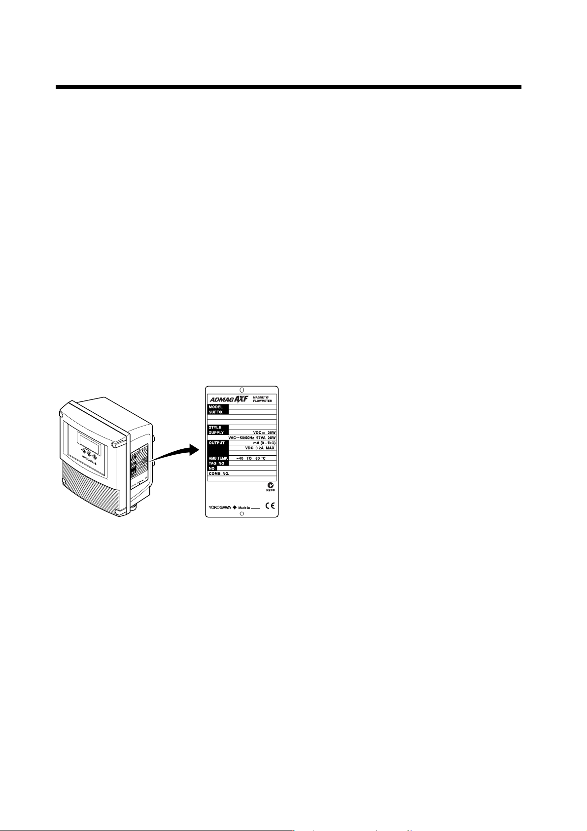
2.1 Checking Model and Specifications
The model code and specifications are found on the
data plate located on the outside of the case. Check
that the model code and specifications match what you
have ordered.
Be sure you have your model number and serial
number available when contacting Yokogawa.
2.3 Storage Precautions
If the instrument is to be stored for a long period of
time after delivery, observe the following points.
The instrument should be stored in its original
packing condition in the storage location.
Select a storage location that fulfils the following
conditions:
• A place where it will not be exposed to rain or
water
• A place subject to minimal vibrations or shocks
• Temperature and humidity levels should be as
follows:
Temperature: -30 to 70°C
Humidity: 5 to 80% RH (no condensation)
The preferred ambient temperature and
humidity levels are 25°C and approximately
65% RH.
If the AXFA11 is transferred to the installation site
and stored without being installed, its performance
may be impaired due to the infiltration of rainwater
and so forth. Be sure to install and wire the
AXFA11 as soon as possible after transferring it to
the installation location.
F0201.EPS
2.2 Accessories
Check that the parts shown below are included in the
package:
Mounting hardware: 1 set
2.4 Installation Location Precautions
Select the installation location with consideration to the
following items to ensure long-term stable operation of
the instrument.
Ambient Temperature:
Avoid installing the instrument in locations with
constantly fluctuating temperatures. If the location is
subject to radiant heat from the plant, provide heat
insulation or improve ventilation.
Atmospheric Condition:
Avoid installing the instrument in a corrosive
atmosphere. In situations where this is unavoidable,
consider ways to improve ventilation and to prevent
rainwater from entering and being retained in the
conduit pipes.
Vibrations or Shocks:
Avoid installing the instrument in a place subject to
shocks or vibrations.
2-1
IM 01E20C01-01E
3. INSTALLATION
3. INSTALLATION
WARNING
Installation of the magnetic flowmeter must be performed by expert engineer or skilled personnel. No
operator shall be permitted to perform procedures relating to installation.
3.1 Installation Location
IMPORTANT
Install the instrument in a location where it is not exposed to direct sunlight. For ambient temperature,
refer to Chapter 11 “OUTLINE”.
The instrument may be used in an ambient humidity where the RH ranges from 0 to 100%. However,
avoid long-term continuous operation at relative humidity above 95%.
3.2 Mounting
This instrument can be mounted using surface mounting, 2-inch pipe mounting, or panel
mounting.
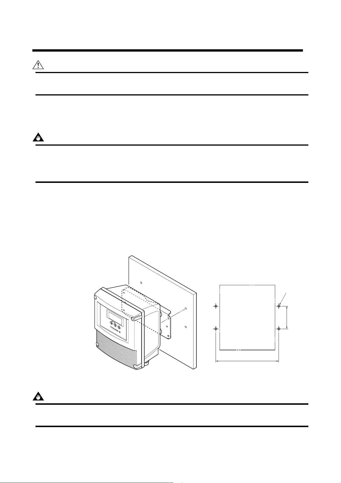
Surface Mounting (Wall Mounting)
Unit: mm
(approx. inch)
For surface mounting, use the mounting
fixture provided, using M6 screws.
These M6 screws must be provided
by the user.
194 (7.64)
4-6 Hole or
M6 Screw
65
(2.56)
F0301.EPS
Figure 3.2.1 Surface Mounting
IMPORTANT
Mounting fixture on equipment intended to be mounted on a wall or ceiling shall withstand a force of four
times the weight of the equipment (AXFA11: 3.3kg (7.3 lb)).
3-1
IM 01E20C01-01E
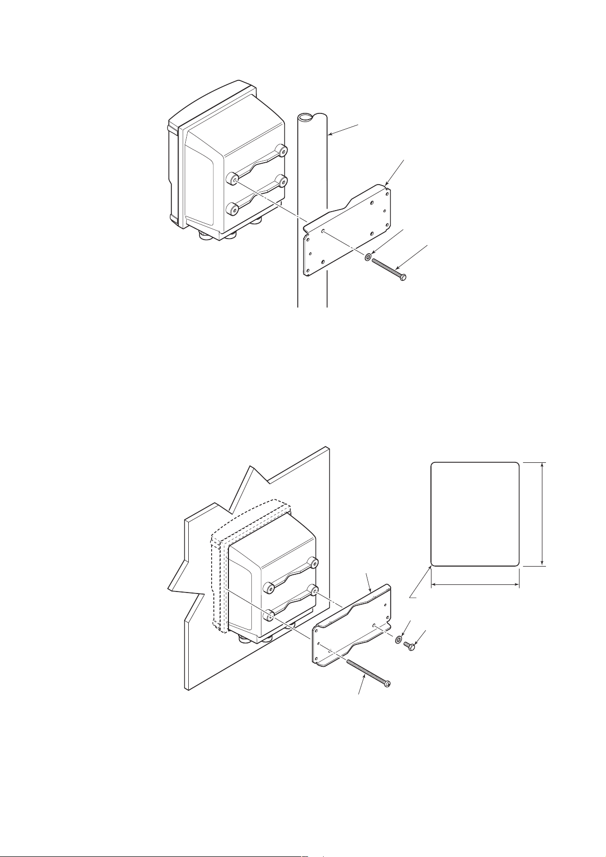
2-inch Pipe Mounting
2-inch pipe
Mounting fixture
Washer
Clamp screw
Pass the four clamp screws through the mounting fixture, position it on the 2-inch pipe,
and then fasten the AXFA11 in place.
3. INSTALLATION
Figure 3.2.2 2-inch Pipe Mounting
Panel Mounting
F0302.EPS
Unit: mm
(approx. inch)
Panel cutout
203 (8.0)
Mounting fixture
172 (6.8)
R3MAX
Washer
Screw
Fit the AXFA11 into the panel. Then attach the mounting fixture to the AXFA11 using the screw and the
washer, and secure the instrument with the two clamp screws.
Figure 3.2.3 Panel Mounting
3-2
Clamp screw
F0303.EPS
IM 01E20C01-01E
4. WIRING
4. WIRING
This section describes the wiring on the converter side
only. For information relating to wiring on the
flowtube side, refer to the user’s manual of the AXF
Remote Flowtube (IM 01E20D01-01E).
WARNING
The wiring of the magnetic flowmeter must be
performed by expert engineer or skilled personnel. No operator shall be permitted to perform
procedures relating to wiring.
CAUTION
Once all wiring is complete, check the connections before applying power to the instrument.
Improper arrangements or wiring may cause a
unit malfunction or damage.
4.1 Wiring Precautions
Be sure to observe the following precautions when
wiring:
four-core cables are used for wiring. Keep
conduits or flexible tubes watertight using
sealing tape.
• Ground the remote flowtube and the converter
separately.
• Cover each shield of the signal cable with vinyl
tube or vinyl tape to avoid contact between two
shields or between a shield and a case.
• When waterproof glands or union equipped
waterproof glands are used, avoid tightening
the glands with an excessive torque.
• Be sure to turn power off before opening the
cover.
• Before turning the power on, tighten the cover
securely.
4.2 Cables
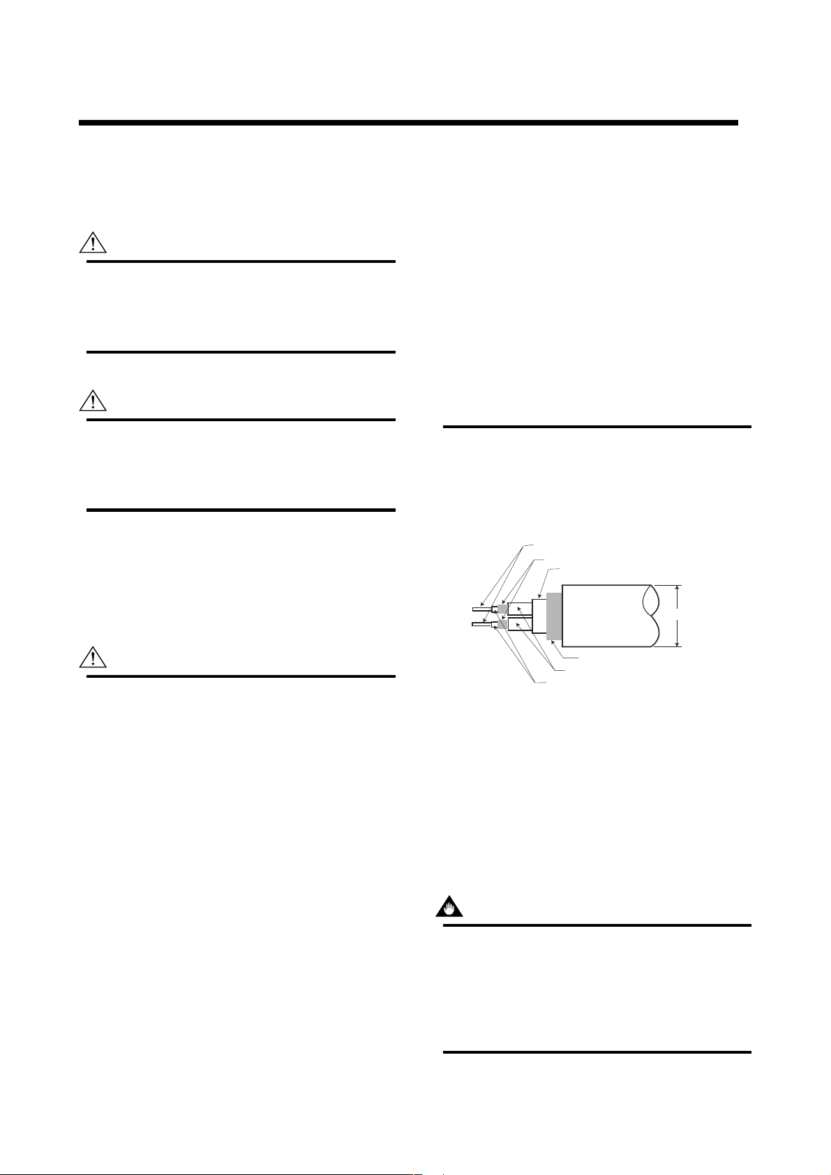
(1) Dedicated Signal Cable (AXFC)
Conductors (A and B)
Shields (SA and SB)
Tape
Outer jacket
10.5 (0.413")
CAUTION
• In cases where the ambient temperature
exceeds 50°C (122°F), use external heatresistant wiring with a maximum allowable
temperature of 70°C (158°F) or above.
• Do not connect cables outdoors in wet weather
in order to prevent damage from condensation
and to protect the insulation.
• Do not splice the cable between the flowtube
terminal and the converter if it is too short.
Replace the short cable with a cable that is the
appropriate length.
• All the cable ends must be provided with round
crimp-on terminals and be securely wired.
• The signal cables must be routed in separate
steel conduit tubes 16 (JIS C 8305) or flexible
conduit tubes 15 (JIS C 8309).
• Always route the power and output signal
cables in separate steel conduit tubes, except
when the power supply voltage is 24 V and
Shield (C)
Insulation
Insulation
Figure 4.2.1 Dedicated Signal Cable AXFC
F0401.EPS
The flow signal is transmitted via this dedicated cable.
The cable is constructed with double shielding over the
two conductors, and heat-resistant vinyl is used for the
outer jacket material.
Finished diameter: 10.5 mm (0.413")
Maximum length: 200 m (660 ft)
Maximum temperature: 80°C (176°F)
IMPORTANT
If the cable is longer than required, cut off any
extra length rather than coiling it up, and terminate the conductors as shown in Figure 4.2.2.
Avoid using junction terminal boards to extend
the cable length, as this will interrupt the shielding.
4-1
IM 01E20C01-01E
4. WIRING
NOTE
Unit : mm
(approx. inch)
ACB
SA
White Black
On the
converter
side
25 (0.98)
5
150
8(0.3) max.
(5.9)
20 (0.8)
SB
50 (1.97)
Red
60 (2.36)
70 (2.76)
L (Specified Dimensions)
AXFC
ACB
55 (2.17)
90 (3.54)
White Black Red
8 (0.3) max.
5
On the
(5.9)
150
flowtube
side
10.5 (0.4)
F0402.EPS
Figure 4.2.2 Treatment of Dedicated Signal Cables
CAUTION
• As crimp terminals A, B, SA, SB and C have
their own electrical potentials, securely insulate
them so as not to come in contact with one
another.
• To prevent a shield from coming in contact with
another shield or the case, cover each shield
with a vinyl tube or wrap it in vinyl tape.
90 (3.54)
With gland options EG, EU and EW;
• Excitation cable;
10.5 or 11.5 mm (0.41 or 0.45 in.)
• Power and output cable;
7.5 to 12 mm (0.30 to 0.47 in.)
With gland options EP;
6 to 12 mm (0.24 to 0.47 in.)
Nominal Cross Section:
Single wire; 0.5 to 2.5 mm
Stranded wire; 0.5 to 1.5 mm
2
2
In case of power cable, Green/Yellow covered conductor shall be used only for connection to PROTECTIVE
CONDUCTOR TERMINALS. Conform to IEC227,
IEC245 or equivalent national authorization.
Unit : mm
(approx. inch)
Crimp Terminal
EX2
EX1
85 (3.35)
On the converter side
85 (3.35)
On the flowtube side
EX1
EX2
NOTE
Conductors A and B carry the signal from the
electrodes, and C is at the potential of the liquid
(signal common). Shields SA and SB are kept
at the same potentials as the individual electrodes (these are actively driven shields.) This is
done to reduce the effect of the distributed
capacitance of the cable at long cable length.
Note that, since the signals from the individual
electrodes are impedance converted inside the
converter, errors will result if they come in
contact with any other component. Great care
must be taken in the cable end treatment.
(2) Excitation Cable/Power Cable/Output
Cable
JIS C3401 control cable equivalent
JIS C3312 power cable equivalent
14 AWG Belden 8720 equivalent
Outer Diameter:
With no gland option;
6.5 to 12 mm (0.26 to 0.47 in.)
F0403.EPS
Figure 4.2.3 End Treatment of Excitation Cable
• For excitation and power cables, always use a
crimp terminal with an insulation cover.
• Use crimp tools from the manufacturer of the
crimp terminal you want to use to connect the
crimp terminal and cable.
• Use crimp tools that are appropriate for the
diameter of the cable to be connected.
4-2
IM 01E20C01-01E

4. WIRING
4.3 Wiring Ports
This instrument is of watertight construction as
stipulated in JIS C0920. It is shipped with a wiring
bracket (waterproof gland or waterproof gland with
union) or a plastic gland attached, only in cases where
an optional specification is selected for the wiring port.
IMPORTANT
The wiring port is sealed with a cap (not waterproof). Do not remove the cap from the unused
wiring port. If waterproof property is necessary,
please use waterproof glands.
(1) When waterproof property is unnecessary
(When there are no particular optional
specifications)
The wiring port is sealed with a cap (not water-proof)
that must be removed before wiring. At this time,
handle the wiring port in accordance with the JIS
C0920 mentioned above. Do not remove the cap from
the unused wiring port.
For working on the electric wire tubes or the flexible
tubes (PF1/2), remove the waterproof gland and attach
them directly to the wiring port.
Washer
PF1/2
Gasket
Tightening gland
Cable
When working on conduit pipes or flexible pipes (PF1/2 only)
F0405.EPS
Figure 4.3.2 Waterproof Gland with Union Joint
(Optional Code EU)
(2) When waterproof property is necessary
(Wiring using waterproof glands)
IMPORTANT
To prevent water or condensation from entering
the converter housing, waterproof glands are
recommended. Do not over-tighten the glands or
damage to the cables may result. Tightness of
the gland can be checked by confirming that the
cable is held firmly in place.
Washer
Gasket
Waterproof gland
Cable
F0404.EPS
Plastic gland
Figure 4.3.3 Plastic Gland (Optional Code EP)
PF1/2
PF3/4
Extension plug (x2)
Conversion plug (x5)
Cable
When working on electric wire tube or flexible tube (PF3/4)
* When connecting PF1/2, remove the conversion plug and
connect directly to wiring port.
Figure 4.3.4 PF3/4 Waterproof Gland (Optional Code EW)
F0406.EPS
Gasket
Washer
Figure 4.3.1 Waterproof Gland (Optional Code EG)
4-3
IM 01E20C01-01E
(3) Conduit Wiring
When wiring the conduits, pass the conduit through the
wiring connection port, and utilize the waterproof
gland to prevent water from flowing in. Place the
conduit pipe on an angle as shown in Figure 4.3.5.
Install a drain valve at the low end of the vertical pipe,
and open the valve regularly.
Drain valve
F0408.EPS
Figure 4.3.5 Conduit Wiring
4. WIRING
4-4
IM 01E20C01-01E
4.4 Wiring Connections
4.4.1 Removing Cover
While supporting the front of the cover with your hand, flip the connecting screw protective cover over, and remove the four connecting screws.
Figure 4.4.1 Removing the Front Cover
4.4.2 Terminal Configuration
When the cover is removed, the connection terminals will be visible. The terminal configuration labels are attached in the position shown in Figure 4.4.2.
4. WIRING
F0409.EPS
SO2+
N/– L/+ EX2EX1 P– SI1+ SI2+ COMP+
AL+ AL– C SA A B SB
ALARM OUT
EX2EX1
PULSE OUT STATUS IN
SIGNAL
P– SI1+ SI2+ COMP+
I+ I–
CURRENT OUT
POWER SUPPLY
SO1+ COMSO2+
STATUS OUT
N/– L/+
I+ I– AL+ AL– C SA A B SBSO1+ COM
EXCIT ATION
Figure 4.4.2 Terminal Layout Labels Position
The description of the terminal symbols is shown in Table 4.4.1.
Table 4.4.1 Terminal Symbols
Terminal Symbols
SIGNAL
ALARM OUT
STATUS OUT
CURRENT OUT
C
SA
A
B
SB
AL+
AL-
SO1+
SO2+
COM
I+
I-
Description
Flow signal input
Alarm output
Status output
(Two output)
Current output
4 to 20mA DC
Terminal Symbols
STATUS IN
PULSE OUT
EXCITATION
POWER SUPPLY
Description
Sl1+
Status input
Sl2+
(Two input)
COM
P+
Pulse output
P-
Excitation current
EX1
EX2
output
L /+
Power supply
N/-
Functional grounding
Protective grounding
(Outside of the terminal)
T0401.EPS
F0410.EPS
4-5
IM 01E20C01-01E

4. WIRING
IMPORTANT
Do not wire the terminal without terminal symbols in terminal layout labels.
4.4.3 Precautions for Wiring of Power Supply Cables
When connecting to the power supply, observe the
points below. Failure to comply with these warnings
may result in an electric shock or damage to the
instrument.
WARNING
• Ensure that the power supply is OFF in order to
prevent electric shocks.
• Ensure the protective grounding terminal is
grounded before turning the power on.
• Use insulating sleeve crimp terminals (for 4-mm
screws) for the power supply wiring and protective grounding wiring.
• To prevent electric shocks, ensure the electrical
wiring cover (transparent) is attached.
• Install an external switch or circuit breaker as a
means to turn the powe off (capacitance; 15A,
conforming to IEC947-1 and IEC947-3). Locate
this switch either near the instrument or in other
places facilitating easy operation. Affix a
“Power Off Equipment” label to this external
switch or circuit breaker.
4.4.4 DC Power Connection
When using DC power as the power supply for the
converter, give attention to the following points.
(1) Connecting Power Supply
IMPORTANT
Do not connect power supply with reversed
polarities.
L/+ terminal: connect +
N/– terminal: connect
IMPORTANT
Do not connect power supply with 100 to 240 V
AC or 100 to 120 V DC in the case of a 24 V
power supply version (power supply code 2).
It will give a damage to the converter.
(2) Required Power Supply Voltages
IMPORTANT
When using a 24 V power supply, the specification for the supply voltage is 24 V (–15% to
+20%), but the input voltage of the converter
drops due to cable resistance therefore it must
be used within the following ranges.
Supply Voltage and Cable Length
–
Wiring Procedure
1. Turn the instrument's power off, and remove the
wiring cover (transparent).
2. Wire the power supply cable and the functional
grounding cable to the power supply terminals.
CUR OUT STATUS OUT ALARM OUT SIGNAL
Functional
grounding cable
Figure 4.4.3 Electric Cable Wiring
POWER SUPPLY EXCITER
P–P+
PULSE OUT STATUS IN
Power supply cable
SBBASACAL–AL+COMSO2+SO1+I+ I–
COMSI2+SI1+EX2EX1L/+N/–
F0411.EPS
3. Reattach the electrical wiring cover (transparent).
420 (1380)
280 ( 920)
200 ( 660)
100 ( 330)
Allowable cable length m(ft)
0
20.4 22 24 26 28.8
Usable range E (V)
Cable cross section area: 1.25 mm
Cable cross section area: 2 mm
(3) Setting Power Supply Frequency
IMPORTANT
Set the local commercial power frequency in
order to eliminate the effect of induction noise
from the commercial power supply.
Refer to “Chapter 6: Parameter Description” in
this manual. Parameter No. J30 and J31.
4-6
2
2
F0411-2.EPS
IM 01E20C01-01E
4. WIRING
4.4.5 Grounding
CAUTION
Be sure to connect the protective grounding of
the AXFA11 with a cable of 2mm2 or larger cross
section in oder to avoid electrical shock to the
operators and maintenance engineers and to
prevent the influence of external noise. Connect
the grounding wire to the mark (100 or
less).
IMPORTANT
When optional code A (lighting protector) is
selected, the ground should satisfy Class C
requirements (grounding resistance, 10 or
less).
• The protective grounding terminals are located
on the inside and outside of the terminal area.
Either terminal may be used.
• Use 600 V vinyl insulation wires as the grounding
wires.
4.4.6 Wiring the Remote Flowtube with the AXFA11 Converter
WARNING
Before wiring, be sure that the power supply for
AXFA11 converter has been turned off to
prevent an electrical shock.
(1) Connection with the Remote Flowtube
(General-Purpose Use, Submersible Type,
Sanitary Type, Size 2.5 to 400 mm (0.1 to
16 in.))
Connect wiring as shown in the figure below.
I+ I–
CURRENT OUT
N/– L/+
POWER SUPPLY
A
B
C
Figure 4.4.5 Wiring Diagram
AL+ AL– C SA A B SB
SO1+ COMSO2+
ALARM OUT
STATUS OUT
EX2EX1
P– SI1+ SI2+ COMP+
EXCIT ATION
PULSE OUT STATUS IN
Excitation cable
Remote flowtube
EX2
EX1
SIGNAL
AXFA11 Converter
AXFC Dedicated signal
cable
Converter
SA
A
B
SB
C
EX1
EX2
* Individually tape and insulate the
shields corresponding to SA and
SB on the remote flowtube side.
Remote
flowtube
Taping*
A
B
Taping*
C
EX1
EX2
F0415.EPS
Protective grounding terminals
F0414.EPS
Figure 4.4.4 Protective Grounding Terminal Location
(2) Connection with the Remote Flowtube
(Explosion proof Type, Size 2.5 to 400 mm
(0.1 to 16 in.))
IMPORTANT
In case of TIIS Flame proof type, a remote
flowtube cannot be combined with AXFA11
converter. In this case, use the AXFA14 converter.
4-7
IM 01E20C01-01E

4. WIRING
In case of explosion proof type for ATEX, FM, and
CSA certification, connect wiring as shown in the
figure below.
In case of the explosion proof type, the protective
grounding
of remote flowtube must be connected to
a suitable IS grounding system. In that case,
(functional grounding terminal) need not be connected.
I+ I–
CURRENT OUT
N/– L/+
POWER SUPPLY
A
B
C
Figure 4.4.6 Wiring Diagram
AL+ AL– C SA A B SB
SO1+ COMSO2+
ALARM OUT
STATUS OUT
EX2EX1
P– SI1+ SI2+ COMP+
EXCIT ATION
PULSE OUT STATUS IN
Excitation cable
Remote flowtube
EX2
EX1
SIGNAL
AXFA11 Converter
AXFC Dedicated signal
cable
Converter
SA
A
B
SB
C
EX1
EX2
* Individually tape and insulate the
shields corresponding to SA and
SB on the remote flowtube side.
Remote
flowtube
Taping*
A
B
Taping*
C
EX1
EX2
F0416.EPS
(4) Connection with the Remote Flowtube
(General-Purpose Use, Submersible Type,
Size 1100 to 2600 mm (44 to 104 in.))
Connect wiring as shown in the figure below.
SO1+ COMSO2+
I+
Shortbar
CURRENT OUT
4-20mA out
N/– L/+
POWER SUPPLY
I–
AL+ AL– C SA A B SB
STATUS OUT
ALARM OUT
EX2EX1
P– SI1+ SI2+ COMP+
EXCIT ATION
PULSE OUT STATUS IN
SIGNAL
AXFA11 converter
AXFC dedicated
signal cable
Excitation
cable
A
EX2
B
C
EX1
Converter
SA
A
B
SB
C
EX1
EX2
* Individually tape and insulate
the shields corresponding to SA
and SB on the remote flowtube
side.
Remote flowtube
Remote
flowtube
Taping*
A
B
Taping*
C
EX1
EX2
F040218.EPS
Figure 4.4.8 Wiring Diagram
4.4.7 Connecting to External Instruments
(3) Connection with the Remote Flowtube
(General-Purpose Use, Submersible Type,
Size 500 to 1000 mm (20 to 40 in.))
Connect wiring as shown in the figure below.
SO1+ COMSO2+
I+
I–
CURRENT OUT
4-20mA out
N/– L/+
POWER SUPPLY
Shortbar
A
B
C
Figure 4.4.7 Wiring Diagram
AL+ AL– C SA A B SB
STATUS OUT
ALARM OUT
EX2EX1
P– SI1+ SI2+ COMP+
EXCIT ATION
PULSE OUT STATUS IN
Excitation
cable
EX2
EX1
Remote flowtube
SIGNAL
AXFA11 converter
AXFC dedicated
signal cable
Converter
SA
A
B
SB
C
EX1
EX2
* Individually tape and insulate
the shields corresponding to SA
and SB on the remote flowtube
side.
Remote
flowtube
Taping*
Taping*
EX1
EX2
F040217.EPS
WARNING
Before wiring with external instrument, be sure to
turn off the power supply for AXFA11 converter
and any external instruments.
Connect the AXFA11 terminal to external instruments,
giving attention to the following points.
4 to 20 mA DC Current Output
A
B
C
AXFA11
l+
Receiver
l-
Instrument
Resistive Load Max. 1 kΩ.
(When using BRAIN/ HART communication,
more than 250 Ω, less than 600 Ω).
Figure 4.4.9 4 to 20 mA DC Output Connection
F0417.EPS
4-8
IM 01E20C01-01E
4. WIRING
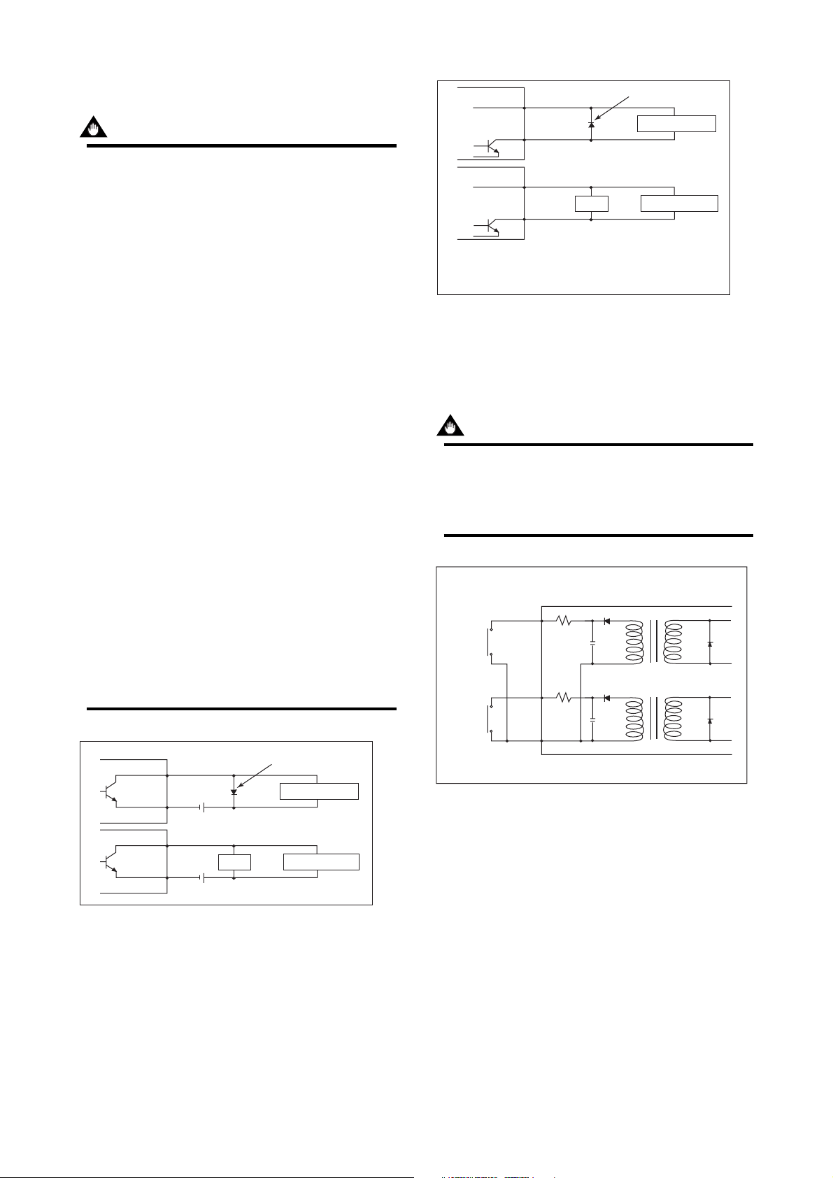
Pulse Output
IMPORTANT
• As this is a transistor contact (insulated type),
give attention to proper voltage and polarity
when wiring.
• Do not apply a voltage larger than 30V DC or a
current larger than 0.2A in order to prevent
damage to the instrument.
• When input filter constant of the electronic
counter is large in relation to the pulse width,
the signal will decrease and the count will not
be accurate.
• If the input impedance of the electronic counter
is large, an induction noise from the power
supply may result in inaccurate counts. Use a
shield cable or sufficiently reduce the input
impedance of the electronic counter within the
electromagnetic flowmeter pulse output specification range.
• The active pulse output (Optional Code EM)
cannot be used in conjunction with the standard
pulse output.
• When the active pulse output (Optional Code
EM) is selected, do not be short-circuit between
the P+ and P– terminals to avoid damaging the
instrument.
• When the active pulse output (Optional code
EM) is selected, the range of pulse rate must
be set to 2 pps maximum.
• To avoid communication (BRAIN/ HART)
failure, it is recommended to use the shield
cable.
AXFA11
PULSE OUT
AXFA11
PULSE OUT
Output voltage: 24 V DC 20%
• Current: 150 mA or less
Pulse rate: 0.0001 to 2 pps
Pulse width: 20, 33, 50, 100 ms
Figure 4.4.11 Active Pulse Output Connection
P+
P-
P+
P-
(Optional code EM)
Load
Protective diode
Mechanical Counter
Electronic Counter
F0419.EPS
Status Input
IMPORTANT
Status inputs are designed for use with novoltage (dry) contacts. Be careful not to connect
the status to any signal source carrying voltage.
Applying voltage may damage the input circuit.
Closed: Less than 200 Ω
Open: More than 100 kΩ
+
SI1
+
SI2
AXFA11
AXFA11
PULSE OUT
AXFA11
PULSE OUT
Figure 4.4.10 Pulse Output Connection
P+
P-
P+
P-
Load
30V DC, 0.2A. max
Protective diode
Mechanical Counter
Electronic Counter
F0418.EPS
COM
No-voltage status input
Figure 4.4.12 Status Input Connection
4-9
F0420.EPS
IM 01E20C01-01E
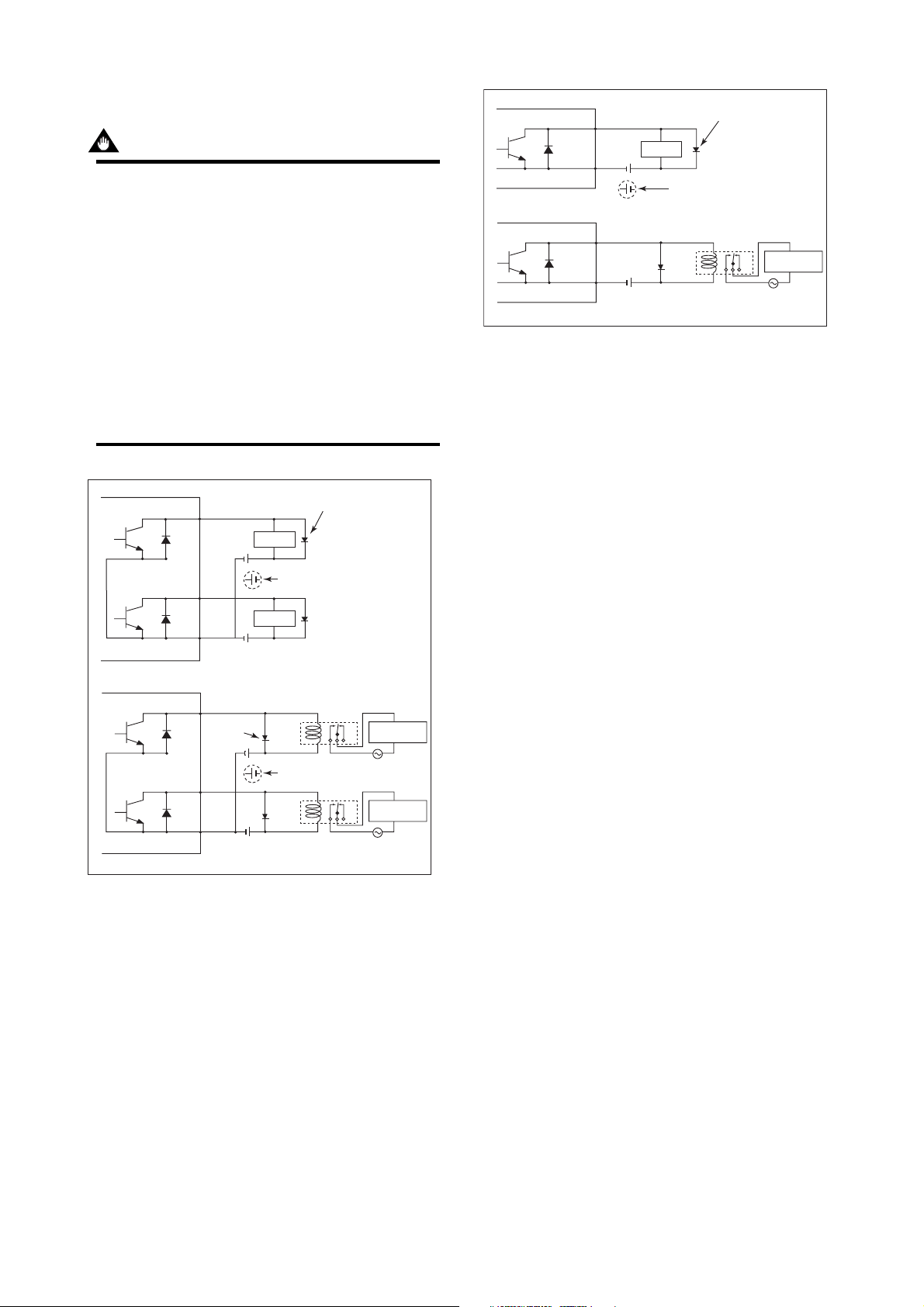
Status Output / Alarm Output
IMPORTANT
Since this is an isolated transistor output, be
careful of voltage and polarity when wiring.
Do not apply a voltage larger than 30V DC or a
current larger than 0.2A in order to prevent
damage to the instrument.
This output cannot switch an AC load. To switch
an AC load, an intermediate relay must be
inserted as shown in Figure 4.4.13 or Figure
4.4.14.
*The alarm output operates from closed (normal)
to open (alarm occurrence) in the default value
(as setup upon plant shipment). Changes can
be made via the parameter settings.
AXFA11
AXFA11
+
AL
Load
-
AL
This connection is not possible.
+
AL
-
AL
External power supply
30V DC, 0.2A. max
Figure 4.4.14 Alarm Output Connection
4. WIRING
Protective diode
Relay
Electromagnetic
AC power supply
valve
F0422.EPS
AXFA11
+
SO1
Load
This connection is not possible.
Load
This connection is not possible.
AXFA11
+
SO2
COM
External power supply
30V DC, 0.2A. max
+
SO1
Protective
diode
+
SO2
COM
External power supply
30V DC, 0.2A. max
Figure 4.4.13 Status Output Connection
Protective diode
Relay
Electromagnetic
Electromagnetic
AC power supply
valve
valve
F0421.EPS
4-10
IM 01E20C01-01E

5. BASIC OPERATING PROCEDURES
5.
BASIC OPERATING PROCEDURES
The modification of data settings from the display unit can be carried out using the three
setting switches (infra-red switches) - namely, the , , and switches.
The infra-red switches enable the user to set parameters without opening the cover.
This chapter will provide a description of basic data configuration and the methods to be
used with the three setting switches. The AXFA11 can also be operated using a handheld
Brain Terminal (BT200) or a HART Communicator. (Please refer to Chapter 7 for operation via Brain Terminal and Chapter 8 for operation via HART Communicator.)
WARNING
Be sure to set parameters as "Protect" on the write protect function after finish of
parameter setting work.
Under extremely rare case, the infra-red switches may respond unexpectedly in
such conditions as sticking ball of water or extraneous substances on the surface
of display panel glass according to the principle of infra-red switch operation.
Its probability rises in such cases as sticking rain water by storm or other similar
situation and washing up work near flowmeter installation place.
Either to illuminate or stop illuminating the infra-red switches by the flashlight may
cause the mis-reaction.
Refer to Chapter 6 "Menu P: Parameter Protection Items" and section "10.2.3"
how to use the write protect function in detail.
(USING THE DISPLAY UNIT)
IMPORTANT
Operate the display unit under the condition where direct sunlight, etc... do not shine
to the setting switches directly when the parameter setting operation is carried out.
NOTE
(1) Always use the setting switches with the cover of the AXFA11 closed.
(2) Use these switches with them covered by the glass window.
(3) If dirt, dust or other substances surfaces on the display panel glass, wipe
them clean with a soft dry cloth.
(4) The operation with dirty gloves may cause a switch response error.
5-1
IM 01E20C01-01E
5. BASIC OPERATING PROCEDURES
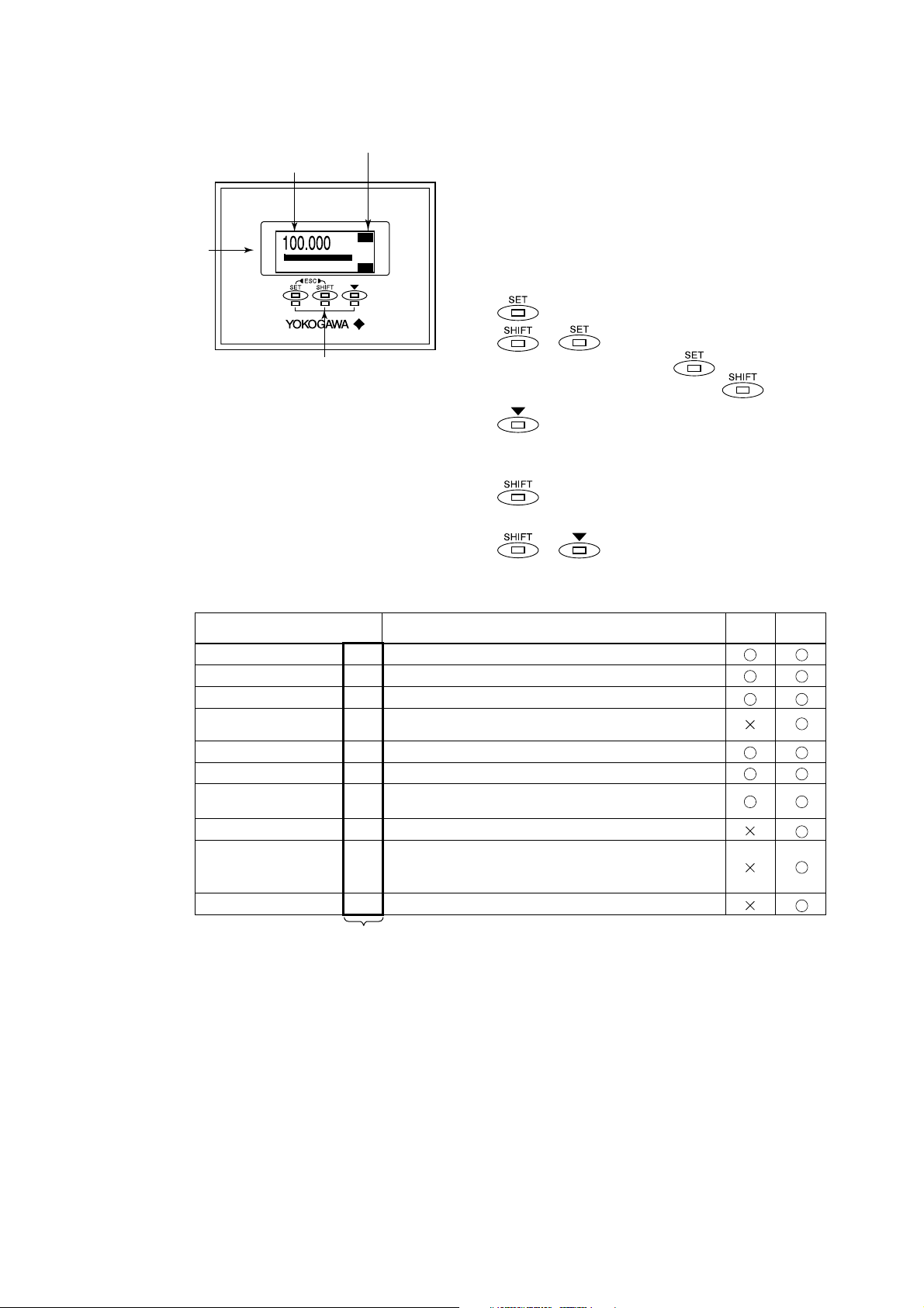
5.1 Operating Panel Configuration and Functions
(4)
(3) Display items
Reversed character display
(1) Data display area
: : :
0
(2) Setting switches
(Infra-red switches)
3274m
3
3
/h
m
100
FTL
FR
F0501.EPS
(1) Data display area
1st line (Display Select1), 2nd line (Display
Select2), and 3rd line (Display Select3) can be
displayed using parameter settings. The content
corresponding to selected item is shown with the
reversed-character on the right of the line.
(2) Setting switch operations
: Move the layer down, select, and confirm
+ : Move the layer up
(Press the switch while
holding down the switch)
: Move the cursor down (for selection-type
parameters) or increase values (for numeric-type parameters)
: Move the cursor to the right (for numeric-
type parameters)
(3) Display items
Displayed items and
reversed-character indication
Instantaneous flow rate: %
Actual instantaneous flow rate
Instantaneous flow rate: mA
Bar graph indicating
instantaneous flow rate
Totalized forward-direction flow rate
Totalized reverse-direction flow rate
Totalized differential flow rate
Tag number
Diagnosis of electrode adhesion
Communication type
+ : Move the cursor up (for selec-
tion-type parameters)
Content
Displays the instantaneous flow rate for the span as a percentage.
FR
Displays the actual reading for instantaneous flow rate.
FR
Displays the instantaneous flow rate for the span as a current output value.
FR
Displays the instantaneous flow rate for the span as a percentage
None
using bar graph.
Displays the totalized value for flow rate in the forward direction.
FTL
Displays the totalized value for flow rate in the reverse direction.
RTL
Displays the differential totalized value for flow rate between
DTL
forward totalization and reverse totalization.
Display the tag number (using up to 16 characters).
TA G
Displays the adhesion condition in the form of a bar graph.
ADH
(See the description for parameters K10 through K15 from
Chapter 6: Parameter Description for more details.)
Displays the communication type.
COM
(4)
Disp Select1
Disp Select2
Disp Select3
T0501.EPS
5-2
IM 01E20C01-01E
5.2 Display Unit Setting Methods
NOTE
Before changing any settings, be sure to check the corresponding setting details
in Chapter 6: Parameter Description.
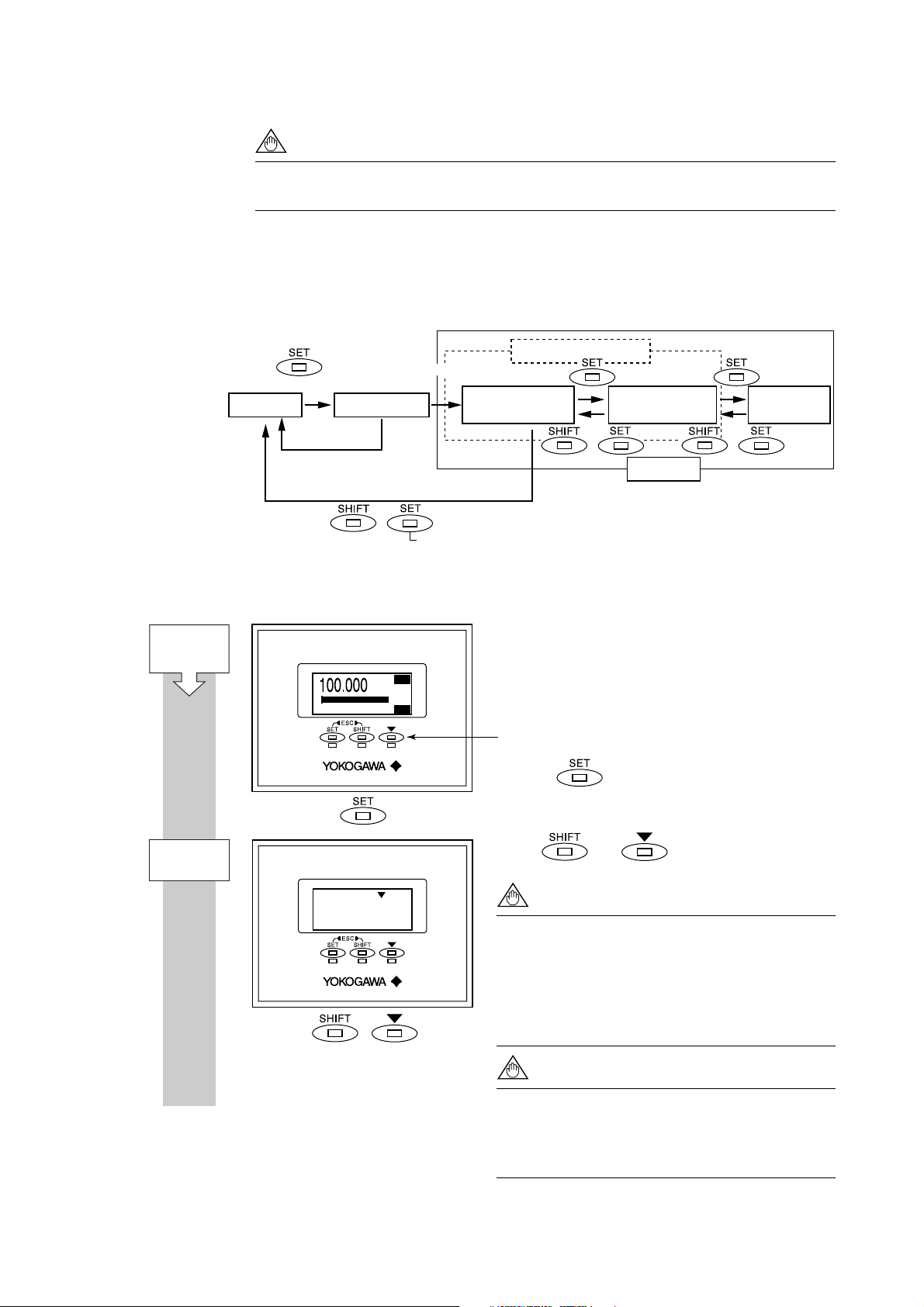
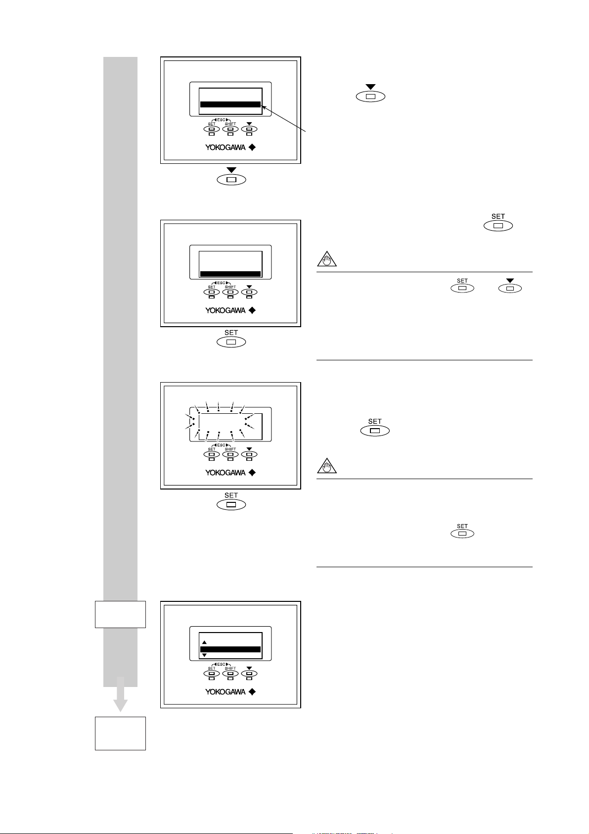
5.2.1 Display Mode → Setting Mode
Display Mode will be adopted when the power is turned on, and the Setting Mode can be
activated using the following procedure.
Parameter Search Mode
(2 seconds or more)
Display Mode
Entry Mode
Select “Yes”
Major Item Parameter
Search Mode
5. BASIC OPERATING PROCEDURES
Sub-item Parameter
Search Mode
Parameter
Replacement Mode
Start:
Display Mode
(*1)
Entry Mode
Select “No”
* The term "mode" is used to refer to a situation
where display and setting are possible.
+
Press the SET switch while holding down the SHIFT switch.
+ +
Setting modes
F0502.EPS
Sample Display: Procedure for moving from Display Mode to Setting Mode
1st line: Actual instantaneous flow rate [FR]
2nd line: Bar graph indicating instantaneous flow
rate
3rd line: Totalized forward flow rate [FTL]
Setting switches
: : :
0
3274m
m
3
FTL
FR
3
/h
100
Hold the switch for 2 seconds.
Touch and switches simultaneously.
Touch SHIFT + key
NOTE
F0503-1.EPS
When other operations are carried out, the
system will automatically return to the Display
Mode.
When no operations in this display are carried
out for 20 seconds, the system will automatically return to the Display Mode.
(*1)
NOTE
The Major Item Parameter which is set just
before will be shown when entrying the Setting
Mode again within 1 minute after returning
from Setting Mode to Display Mode.
5-3
IM 01E20C01-01E
Setting Mode
No
Yes
Setting Mode
No
Yes
5. BASIC OPERATING PROCEDURES
A screen is displayed to confirm whether or not the
system is to enter Setting Mode.
Press the
The reversed-character (i.e. the cursor position)
indicates the item that is currently selected.
switch and select [Yes].
When [Yes] has been selected, touch the
switch.
NOTE
When the operations except and
switches are carried out, the system will
automatically return to the Display Mode.
When no operations in this display are carried
out for 20 seconds, the system will automatically return to the Display Mode.
Setting Mode
Setting Mode
Yes
Setting Mode
P:Protect
B:Easy Setup
C:Basic Setup
In order to request confirmation, the entire display
flashes on and off.
Touch the switch once again at this time to
fix your selection.
NOTE
When no operations in the flashed display are
carried out for 20 seconds, the system will
automatically return to the Display Mode.
When the operations except are carried
out, the system will automatically return to the
Display Mode.
The system enters Setting Mode.
Parameters to be set can be selected.
To Parameter
Search Mode
F0503-2.EPS
This completes the procedure for changing from the
Display Mode to the Parameter Search Mode.
5-4
IM 01E20C01-01E

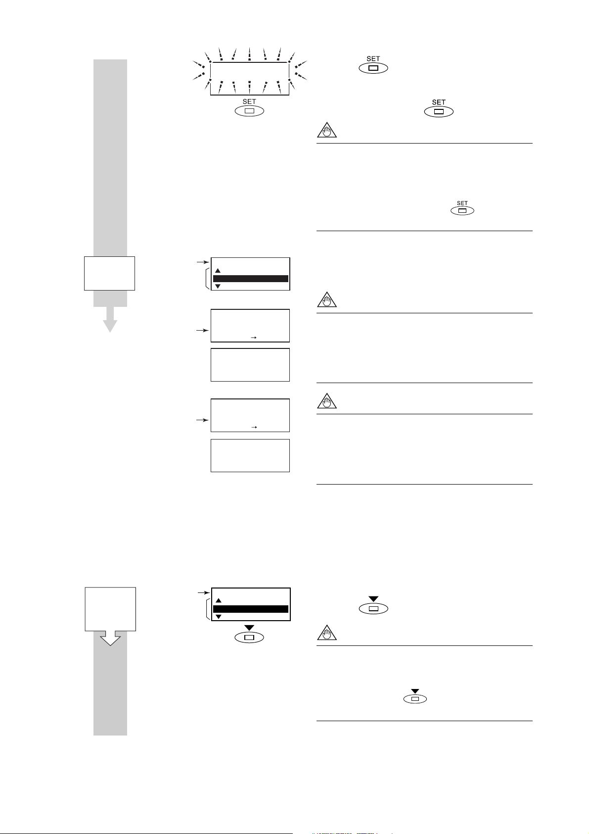
5.2.2 Setting Mode
When the Setting Mode has been activated using the procedure from Section 5.2.1, parameters can be selected for setting.
Format for Parameter Data
Depending on the type of parameter, data is formatted in one of the following three ways.
5. BASIC OPERATING PROCEDURES
NOTE
If no operations are carried out for a period of 10 minutes in Setting Mode, the
system will automatically return to the Display Mode.
Format Typical display Content
(i) Selection-type
(ii) Numeric-type
(iii) Alphanumeric-type
Regarding the alphanumeric-type format (iii), the following alphanumerics are displayed in the following sequence:
#%&*+-./0123456789:<>ABCDEFGHIJKLMNOPQRSTUVWXYZabcdefghij
klmnopqrstuvwxyz[space]
B21:Base Flow Unit
3
m
3
m
kl(Kiloliter)
B23:Flow Span
100 l/min
000100 l/min
Rng:0.00001 32000
C10:Tag No
FI-1101
FI-1201
The desired data item is selected from a predefined list.
Data is set using the values in each digit and using
the decimal point.
Data is composed using alphanumeric characters
(in the case of tag numbers, special units, and the like).
With this format, setting can be carried out using up to
16 of the characters shown below.
T0502.EPS
5.3 Parameter Setting Procedure
Once the system is in Setting Mode, the parameters for setting can be selected. On the
AXFA11, parameters that are frequently used have been grouped together in Easy Setup in
Menu B. This section provides a description of the parameter setting procedure using B:
Easy Setup and C: Basic Setup.
For more details regarding parameter content, please refer to Section 6: Parameter Description.
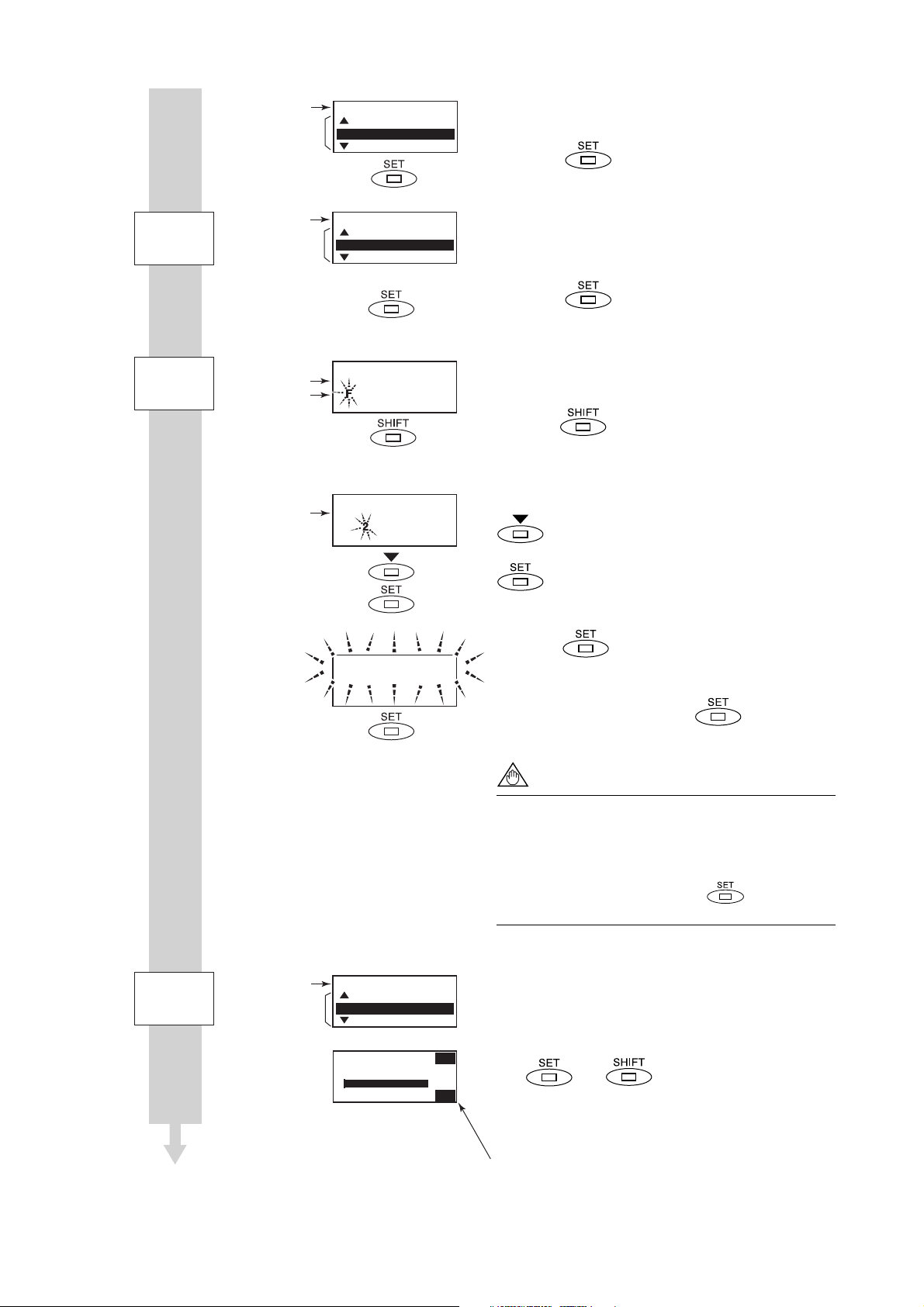
5.3.1 Setting Example for Selection-Type Data: Flow rate units
This example describes the setting of the flow rate units for the selection-type parameter
B21: Base Flow Unit from m3 to l (Liter).
Start:
Major Item
Parameter
Search Mode
Setting Mode
Major item
parameter
Setting Mode
P:Protect
B:Easy Setup
C:Basic Setup
F0504-1.EPS
Major Item Parameter Search Mode has been
accessed in this screen.
Touch the switch to access B: Easy Setup.
NOTE
The and symbols to the left of the param-
eters indicate that additional setting items to
those being currently displayed may also be
selected. Use the switch to cycle
through these items.
5-5
IM 01E20C01-01E

5. BASIC OPERATING PROCEDURES
Sub-item
Parameter
Search Mode
Parameter
Replacement Mode
Current unit setting
Available selections
Current unit setting
Available selections
Major item
Sub-item
parameter
Major item
Sub-item
selection (A)
Sub-item
Sub-item
B:Easy Setup
50:Auto Zero Exe
10:Language
20:Flow Damping
B:Easy Setup
20:Flow Damping
21:Base Flow Unit
22:Base Time Unit
B21:Base Flow Unit
3
m
3
m
kl(Kiloliter)
B21:Base Flow Unit
3
m
l(Liter)
3
cm
Sub-item Parameter Search Mode has been accessed
in this screen.
Touch the
X
2
B21: Base Flow Unit.
switch to move the cursor to
The cursor has been moved to B21: Base Flow
Unit in this screen. (Sub-item selection screen (A))
In this screen, Parameter Replacement Mode has
been called up using the switch.
Touch the switch to move the cursor to the
unit item for selection. In this example, the
switch is touched twice to select l (Liter)
X
2
B21:Base Flow Unit
l(Liter)
When l (Liter) has been selected, touch the
switch.
In order to request confirmation, the entire display
flashes on and off.
Touch the switch once again at this time to
fix your selection.
NOTE
When no operations are carried out for 20
seconds in the flashing state, the system will
automatically return to the Sub-item Parameter
Search Mode.
When the operations except are carried
out, the parameter cannot be set.
Sub-item
Parameter
Search Mode
Major item
Sub-item
selection (A)
B:Easy Setup
20:Flow Damping
21:Base Flow Unit
22:Base Time Unit
F0504-2.EPS
The system returns automatically to sub-item
selection screen (A).
5-6
IM 01E20C01-01E

5. BASIC OPERATING PROCEDURES
5.3.2 Setting Example for Numeric-Type Data: Flow rate span
This example describes the setting of the flow rate span for the numeric-type parameter
B23: Flow Span from 100 l/min to 120 l/min.
Start:
Major Item
Parameter
Search Mode
Sub-item
Parameter
Search Mode
Setting mode
Major item
parameter
Major item
Sub-item
parameter
Major item
Sub-item
selection (B)
Setting Mode
P:Protect
B:Easy Setup
C:Basic Setup
B:Easy Setup
50:Auto Zero Exe
10:Language
20:Flow Damping
X
4
B:Easy Setup
22:Base Time Unit
23:Flow Span
24:Flow Decimal Pnt
Selection of the appropriate parameter
Setting Mode Condition
Touch the switch to access B: Easy Setup.
NOTE
The and symbols to the left of the
parameters indicate that additional setting
items to those being currently displayed may
also be selected. Use the
switch to
cycle through these items.
Sub-item Parameter Search Mode has been accessed
in this screen.
Touch the switch to move the cursor to
B23: Flow Span.
The cursor has been moved to B23: Flow Span in
this screen. (Sub-item selection screen (B))
Touch the switch to access Parameter
Replacement Mode.
Parameter
Replacement Mode
B23:Flow Span
100 l/min
000100. l/min
Rng:0.00001 32000
B23:Flow Span
100 l/min
0000100. l/min
Rng:0.00001
32000
X
X
F0505-1.EPS
4
2
Once Parameter Replacement Mode has been
selected, the digit that can be replaced will be flashed
on and off. When in this condition, confirm the
relevant setting range as displayed at the bottom of
the screen and then set the parameter as required.
In this example, the parameter will be set to “120 l/
min”.
NOTE
When setting a new value, use the switch
to move from digit to digit, and use the
switch to cycle through values for each individual digit. In addition to digit, it is also possible
to select a decimal point, and this allows the
position of the decimal point to be changed.
Modify the value to “120 l/min” as follows:
Touch the switch to move the cursor to the
position for multiples of 10. Then, touch the
switch to change the value at this position from “0” to
“2”. When the value of “120” has been setup, touch
the switch.
5-7
IM 01E20C01-01E
5. BASIC OPERATING PROCEDURES
Sub-item
Parameter
Search Mode
Major item
Sub-item
selection (B)
Incorrect setting:
B23:Flow Span
120 l/min
B:Easy Setup
22:Base Time Unit
23:Flow Span
24:Flow Decimal Pnt
B23:Flow Span
100 l/min
1200000 l/min
Rng:0.00001 32000
Out of range.
Touch any key.
When the switch is touched, the entire
display flashes on and off. Confirm that the setting
has been correctly changed to “120”, and then fix
this value by touching the switch once again.
NOTE
When no operations are carried out for 20
seconds in the flashing state, the system will
automatically return to the Sub-item Parameter
Search Mode.
When the operations except are carried
out, the parameter cannot be set.
The system automatically returns to sub-item
selection screen (B).
NOTE
If the input value is outside the valid selection
range, the message “Out of range. Touch any
key.” will be displayed. In such a case, touch
any switch to return to Parameter Replacement
Mode and redo the setting.
Incorrect setting:
B23:Flow Span
100 l/min
0001.0. l/min
Rng:0.00001
Invalid value.
Touch any key.
32000
NOTE
If more than one decimal point has been input,
the message “Invalid value. Touch any key.”
will be displayed. In such a case, touch any
switch to return to Parameter Replacement
F0505-2.EPS
Mode and redo the setting.
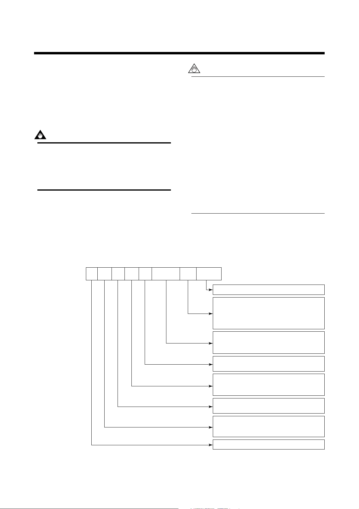
5.3.3 Setting Example for Alphanumeric-Type Data: Tag number
This example describes the setting of the tag number for the alphanumeric-type parameter
C10: Tag No. from “FI-1101” to “FI-1201.”
Start:
Major Item
Parameter
Search Mode
Setting mode
Major item
parameter
Setting Mode
P:Protect
B:Easy Setup
C:Basic Setup
F0506-1.EPS
Setting Mode Condition
Touch the switch to access C: Basic Setup.
NOTE
The and symbols to the left of the parameters indicate that additional setting items to
those being currently displayed may also be
selected. Use the switch to cycle through
these items.
5-8
IM 01E20C01-01E
5. BASIC OPERATING PROCEDURES
Sub-item
Parameter
Search Mode
Parameter
Replacement Mode
Current setting value
Modified value
Current setting value
Setting mode
Major item
parameter
Major item
Sub-item
selection (C)
Setting Mode
B:Easy Setup
C:Basic Setup
D:Total Set
C:Basic Setup
49:Flow User Span
10:Tag No
11:Flow Damping
Selection of the appropriate parameter
C10:Tag No
Fl-1101
l-1101
X
4
C10:Tag No
Fl-1101
Fl-1 01
The cursor has been moved to C: Basic Setup in
this screen.
Touch the
switch to enter C: Basic Setup.
Upon selection of C: Basic Setup, the cursor will
be positioned at C10: Tag No. (Sub-item selection
screen (C))
Touch the switch to access Parameter
Replacement Mode.
The cursor will flash on and off on the left of the tag
number. As “FI-1201” is to be setup in this example,
touch the switch to move the cursor to the
position for multiples of 100.
At the position for multiples of 100, touch the
switch to change the “1” to “2”. When the
setting has been changed to “FI-1201”, touch the
switch.
Sub-item
Parameter
Search Mode
Major item
Sub-item
selection (C)
C10:Tag No
Fl-1201
C:Basic Setup
49:Flow User Span
10:Tag No
11:Flow Damping
108.0
: : :
0
Fl-1201 TAG
FR
l/min
100
F0506-2.EPS
When the switch is touched, the entire
display flashes on and off. Confirm that the setting
has been correctly changed to “FI-1201”, and then
fix this setting by touching the switch once
again.
NOTE
When no operations are carried out for 20
seconds in the flashing state, the system will
automatically return to the Sub-item Parameter
Search Mode.
When the operations except are carried
out, the parameter cannot be set.
The system automatically returns to sub-item
selection screen (C).
After returning to Display Mode by touching using
the ( and ) twice as escape switches,
it will be possible to confirm the modified content (if
Display Select has been setup to display the tag
number.)
Indicates selection of Tag No display for B42: Display Select3.
5-9
IM 01E20C01-01E
6. PARAMETER DESCRIPTION
NOTE
6. PARAMETER DESCRIPTION
6.1 Parameters
With the exception of parameters that were specified
by the customer upon ordering, all of the AXFA11’s
internal parameters will initially be set to default
values. Actions such as the modification of display
details can then be carried out whenever necessary.
IMPORTANT
Make sure to keep the AXFA11’s power on at
least for 30 seconds after you set the parameters. If you turn the power off immediately after
the parameters are set, the settings will be
canceled.
6.2 Parameter Lists
Parameter lists are comprised of the following items.
In order to ensure that correct flow rate data can
be acquired, it is crucial that the nominal size,
flow rate span, and meter factor of the combined
remote flowtube are setup. In cases where a
remote flowtube is ordered at the same time as
the AXFA11, the nominal size and meter factor
will be setup upon shipment from the manufacturing plant, and these will not require additional
setting. If the AXFA11 is ordered individually, the
default value will be setup for the meter factor;
accordingly, it will be necessary to change this
setting to the meter factor indicated on your
remote flowtube data plate.
If a flow rate span is specified upon ordering,
this will be set before shipment. If this is not the
case, however, it will be necessary for the
appropriate value to be set up by the user.
Item Name
R/W
Data
range
Units
Position of
decimal point
Default
value
Description
Describes the parameter content.
The default value (as setup upon plant shipment).
If marked “(*)”, it indicates that the appropriate
setting has been made in accordance with
ordering information and data for a remote
flowtube to be combined.
The position of the decimal point within the data
range and also the allowed relocation range in
terms of places of decimals.
The units corresponding to the data range.
This item defines the range of data to be set for
numeric parameters and also defines selection of
data for selection-type parameters.
R: Read only
W: Writable
The name of the parameter. Entries in parentheses
indicate the parameter name displayed on the
handheld BRAIN Terminal (BT200).
Parameter number.
T0601.EPS
6-1
IM 01E20C01-01E
Loading...