


 Loading...
User’s
Manual Model SIND (Style R)
Integrator
IM 01B04M01-02E
IM 01B04M01-02E
9th Edition

Toc-1
Model SIND (Style R)
Integrator
IM 01B04M01-02E 9th Edition
Contents
1. INTRODUCTION........................................................................................... |
1-1 |
||
1.1 |
Inspection |
................................................................................................................. |
1-2 |
1.2 |
Documentation Conventions.................................................................................. |
1-3 |
|
1.3 |
Notice ........................................................................................................................ |
|
1-3 |
1.4 |
About Compatibility with the Conventional Model (Style A)............................... |
1-5 |
|
2. GENERAL..................................................................................................... |
|
2-1 |
|
2.1 |
Standard Specifications.......................................................................................... |
2-2 |
|
2.2 |
Model and Suffix Codes .......................................................................................... |
2-3 |
|
2.3 |
Accessory |
................................................................................................................. |
2-3 |
3. INSTALLATION ............................................................................................ |
|
3-1 |
|
3.1 |
External Wiring......................................................................................................... |
3-1 |
|
3.2 |
Connecting the SICD Counter ................................................................................ |
3-2 |
|
3.3 |
Connector a Third-party Counter........................................................................... |
3-3 |
|
|
3.3.1 Attaching an external power supply ........................................................ |
3-3 |
|
|
3.3.2 Transistor input electronic counter.......................................................... |
3-4 |
|
4. PRINCIPLES OF OPERATION..................................................................... |
4-1 |
||
4.1 |
Principle of Operation ............................................................................................. |
4-1 |
|
5. SETTING....................................................................................................... |
|
5-1 |
|
5.1 |
Names of Components............................................................................................ |
5-2 |
|
5.2 |
Setting Jumper......................................................................................................... |
5-3 |
|
|
5.2.1 |
Check of Setting Jumper and Location ................................................... |
5-3 |
5.3 |
Setting of Parameters.............................................................................................. |
5-4 |
|
|
5.3.1 |
Parameter Change Disable Function...................................................... |
5-4 |
|
5.3.2 Setting Parameters Using Display Setter (SIND-x04)............................. |
5-4 |
|
|
5.3.3 |
Setting Parameters Using Handy Terminal............................................. |
5-8 |
5.4 |
Parameter List.......................................................................................................... |
5-9 |
|
6. MAINTENANCE............................................................................................ |
|
6-1 |
|
6.1 |
Test Equipments...................................................................................................... |
6-1 |
|
6.2 |
Check of I/O.............................................................................................................. |
6-1 |
|
|
6.2.1 |
Wiring ...................................................................................................... |
6-2 |
|
6.2.2 |
Checking procedure ................................................................................ |
6-2 |
6.3 |
Replacement of Fuse............................................................................................... |
6-3 |
|
6.4 |
Replacement of Capacitor ...................................................................................... |
6-3 |
|
7. TROUBLESHOOTING .................................................................................. |
7-1 |
||
7.1 |
Troubleshooting Flowchart .................................................................................... |
7-1 |
|
7.2 |
Action in Fault Condition ........................................................................................ |
7-2 |
|
7.3 |
Replacement of Parts .............................................................................................. |
7-3 |
|
|
7.3.1 |
Replacement Procedure ......................................................................... |
7-3 |
|
7.3.2 |
Replacement of Power Supply Unit ........................................................ |
7-4 |
|
7.3.3 |
Replacement of Main Board.................................................................... |
7-4 |
|
7.3.4 Replacement of Display (SIND-x04 only) ............................................... |
7-4 |
|
|
|
|
|
|
|
IM 01B04M01-02E |
9th Edition : 2004.05.01-00 |

Toc-2
Appendix /TB Power Supply Terminal Connections (Option) ................ |
App.-1 |
|
Appendix-1 |
GENERAL ............................................................................................ |
App.-1 |
Appendix-2 |
APPLICABLE INSTRUMENTS ........................................................... |
App.-1 |
Appendix-3 |
NAMES OF PARTS & POWER TERMINAL SYMBOLS .................... |
App.-1 |
Appendix-4 |
POWER SUPPLY AND GROUND WIRING ........................................ |
App.-2 |
IM 01B04M01-02E 9th Edition : 2004.05.01-00

<Toc> |
<1. INTRODUCTION> |
1-1 |
|
|
|
1.INTRODUCTION
This manual describes the functions and operations of the SIND Integrator.
Intended Readers
This manual is intended for personnel in charge of:
zInstallation and wiring
zInstrumentation and setup of functions
zOperation and monitoring of the controller
zMaintenance of equipment
Related Documents
The following documents all relate to the SIND Integrator. Read them as necessary. The codes enclosed in parentheses are the document numbers.
z Rack-Mounted Instruments |
(IM 1B4F2-01E) |
Describes mounting and wiring for YS80 rack-mounted instruments.
z Model JHT200 Handy Terminal |
(IM JF81-02E) |
Describes operation of JHT200. |
|
z YEWSERIES 80 Installation Manual |
(TI 1B4A9-01E) |
Describes the installation conditions of YS80 instruments. |
|
IM 01B04M01-02E 9th Edition : 2004.05.01-00
<Toc> |
<1. INTRODUCTION> |
1-2 |
|
|
|
1.1Inspection
The SIND integrator is shipped only after stringent inspection at the factory. Visually inspect the product upon delivery to make sure it is not damaged in any way.
Store the box and inner packing material of the package in a safe place / they may be needed if there is a problem with the product and it needs to be sent back for repair.
Check of Model and Suffix Codes
The model and suffix codes are indicated on the Name plate attached to the front cover of the instrument. Crosscheck this information with the model and suffix codes of Section 2.2 to ensure that the product is as specified in the order.
INTEGRATOR
MODEL SIND
SUFFIX -104*R
SUPPLY 80-138VAC 47-63 Hz
/20-130VDC 250mA AT 20VDC
|
|
INPUT |
1 5 V DC |
|
||
|
|
MODEL |
Type K |
|
|
|
|
|
NO. |
|
|
|
|
|
|
YOKOGAWA |
Made in Korea |
|
||
|
|
Yokogawa Electric Corporation |
||||
Figure 1-1 Name Plate |
|
|
||||
Confirmation of the Package Contents
Check the package contents against the list below. If anything is missing or damaged, immediately contact the sales office from which you purchased the product or your nearest Yokogawa representative.
z SIND Integrator............................................................................................... |
1 |
z Integrating ratio label (Parts No.:L4040JA)..................................................... |
1 sheet |
z Fuse (Parts No.: S9510VK) ............................................................................ |
1 |
z User’s Manual (This manual).......................................................................... |
1 |
IM 01B04M01-02E 9th Edition : 2004.05.01-00

<Toc> |
<1. INTRODUCTION> |
1-3 |
|
|
|
1.2Documentation Conventions
This manual uses the following notational conventions.
Symbols
The following symbols are used in this manual.
WARNING
Indicates that operating the hardware or software in a particular manner may damage it or result in a system failure.
NOTE
Draws attention to information that is essential for understanding the operation and/or features of the product.
TIP
Gives additional information to complement the present topic and/or describes terms specific to this document.
See Also
Gives reference locations for further information on the topic.
Description of Displays
Some of the representations of product displays shown in this manual may be exaggerated, simplified, or partially omitted for reasons of convenience when explaining them.
1.3Notice
This User’s Manual
zThis manual should be passed on to the end user. Keep at least one extra copy of the manual in a safe place.
zRead this manual carefully to gain a thorough understanding of how to operate this product before you start using it.
zThis manual is intended to describe the functions of this product. Yokogawa Electric Corporation (hereinafter simply referred to as Yokogawa) does not guarantee that these functions are suited to the particular purpose of the user.
zUnder absolutely no circumstances may the contents of this manual, in part or in whole, be transcribed or copied without permission.
zThe contents of this manual are subject to change without prior notice.
zEvery effort has been made to ensure accuracy in the preparation of this manual. Should any errors or omissions come to your attention however, please contact your nearest Yokogawa representative or sales office.
IM 01B04M01-02E 9th Edition : 2004.05.01-00

<Toc> |
<1. INTRODUCTION> |
1-4 |
|
|
|
Protection, Safety, and Prohibition against Unauthorized Modification
zIn order to protect the product and the system controlled by it against damage and ensure its safe use, make certain that all of the instructions and precautions relating to safety contained in this document are strictly adhered to. Yokogawa does not guarantee safety if products are not handled according to these instructions.
zThe following safety symbols are used on the product and in this manual.
If this symbol is indicated on the product, the operator should refer to the explanation given in the user’s manual in order to avoid personal injury or death to either themselves or other personnel, and/or damage to the instrument. The manual describes that the operator should exercise special care to avoid shock or other dangers that may result in injury or loss of life.
Protective ground terminal:
This symbol indicates that the terminal must be connected to ground prior to operating the equipment.
Function ground terminal:
This symbol indicates that the terminal must be connected to ground prior to operating the equipment.
AC voltage:
This symbol indicates that AC voltage is present.
DC voltage:
This symbol indicates that DC voltage is present.
zDo not turn off the power of the product during adjustment.
zBe sure to confirm the parameters referring to ''5.4 Parameter List'' before installing the product in a system or plant. After confirming them, install the product in a system or plant and turn on the power.
zIf protection/safety circuits are to be used for the product or the system controlled by it, they should be externally installed on the product.
zWhen you replace the parts or consumables of the product, only use those specified by Yokogawa.
zDo not modify the product.
Force Majeure
zYokogawa does not make any warranties regarding the product except those mentioned in the WARRANTY that is provided separately.
zYokogawa assumes no liability to any party for any loss or damage, direct or indirect, caused by the use or any unpredictable defect of the product.
IM 01B04M01-02E 9th Edition : 2004.05.01-00

<Toc> |
<1. INTRODUCTION> |
1-5 |
|
|
|
1.4About Compatibility with the Conventional
Model (Style A)
zThe operation and function differ from the conventional model.
Read this manual carefully to gain a thorough understanding of how to operate this product before you start using it.
zBe sure to confirm the parameters such as integrating ratio set point and setting jumper referring to ''5. Setting'' before installing the product in a system or plant. After confirming them, install the product in a system or plant and turn on the power.
IM 01B04M01-02E 9th Edition : 2004.05.01-00

<Toc> |
<1. INTRODUCTION> |
1-6 |
|
|
|
Blank Page
IM 01B04M01-02E 9th Edition : 2004.05.01-00

<Toc> |
<2. GENERAL> |
2-1 |
|
|
|
2.GENERAL
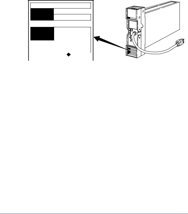
The SIND Integrator is a voltage-to-pulse converter that converts 1 to 5 V DC inputs to corresponding pulse frequency output. It can be used with a YS80 series SICD counter to totalize flow quantity.
Two integrating modes are available: proportional integration that directly totalizes the input, and square root integration that totalizes square-root values.
The JHT200 Handy Terminal (*1) is used for setting the SIND parameters.
On the SIND model with display setter (SIND-x04), input indication can be displayed and integrating ratio and low input cut off can be displayed / set on the front panel.
*1: The modular jack conversion adapter (E9786WH) is required for connecting the JHT200 Handy Terminal to the Integrator.
The 5 pin-connector type communication cable (F9182EE) and modular jack conversion adapter (E9786WH) is required for connecting the BT200 BRAIN Terminal of YOKOGAWA ELECTRIC Corporation
Figure 2-1 External View
IM 01B04M01-02E 9th Edition : 2004.05.01-00

<Toc> |
<2. GENERAL> |
2-2 |
|
|
|
2.1Standard Specifications
The following table shows the SIND standard specifications.
Table 2-1 Standard Specifications
Item |
|
|
|
|
Description |
|
Input Signal |
1 to 5 V DC |
Input resistance: 1MΩ 1 point |
|
|||
Output Signal |
SICD counter drive pulse (24 V DC) or transistor contact 2 points (*1) |
|||||
|
• |
Pulse ON time: 30 ms or 60 ms (*1) |
|
|||
|
• |
Load: |
|
SICD counter drive pulse |
150 mA or less |
|
|
|
|
|
Transistor contact pulse |
30 V DC 150 mA or less |
|
Integrating Ratio (*2) |
1 to 10,000 pph/full scale |
|
|
|||
Integration Method |
Proportional integration or square root integration |
|||||
Low Input Cutoff (*2) |
Proportional integrating type: Cut-off point can be set within 0 to 10% of |
|||||
|
|
|
|
input signal. |
|
|
|
Square root integrating type: Cut-off point can be set within 0.3 to 10% of |
|||||
|
|
|
|
input signal. |
|
|
Accuracy |
±0.5% of span (at output 10% or more on a square root integrating type) |
|||||
Power Voltage |
100 V version: |
With DC drive, 20 to 130 V (no polarity) |
||||
For both DC/AC |
|
|
With AC drive, |
80 to 138 V, 47 to 63 Hz |
||
|
220 V version: With DC drive, 120 to 340 V (no polarity) |
|||||
|
|
|
With AC drive, |
138 to 264 V, 47 to 63 Hz |
||
Current/Power |
Integrating ratio at 1000 pph: |
100 mA at 24 V DC, 7.3 VA at 100 V AC, |
||||
Consumption |
|
|
|
|
10.2 VA at 220 V AC |
|
|
Integrating ratio at 10000 pph: |
190 mA at 24 V DC, 10.8 VA at 100 V AC, |
||||
|
|
|
|
|
13.7 VA at 220 V AC |
|
Ambient Temperature |
0 to 50°C, 5 to 90%RH (non-condensing) |
|
||||
and Ambient Humidity |
|
|
|
|
|
|
Mounting and Wiring |
Mounting: |
|
Indoor, rack mounting |
|||
|
Signal connection: |
M4 screw terminal connection |
||||
|
Power supply connection: Power plug or M4 screw terminal connection |
|||||
Weight |
Approx. 1.7 kg (including rack and case) |
|
||||
*1: The time becomes 60 ms by shorting the A and C terminals. The number of outputs at this time is one. *2: Can be set and changed on the JHT200 Handy Terminal.
On the SIND-x04, can be set and changed on the display setter.
IM 01B04M01-02E 9th Edition : 2004.05.01-00
<Toc> |
<2. GENERAL> |
2-3 |
|
|
|
2.2Model and Suffix Codes
The following table shows the SIND model and suffix codes.
Table 2-2 Model and Suffix Codes
Model |
Suffix Codes |
Sytle |
Optional |
Description |
||
Suffix Codes |
||||||
|
|
|
|
|
||
SIND |
|
|
|
|
Integrator |
|
Square-root |
-1 |
|
|
|
Not proviced (proportional output) |
|
integration mode |
-2 |
|
|
|
Provided (square-root output)(*1) |
|
Display setter |
|
00 |
|
|
Not provided |
|
|
|
04 |
|
|
Provided |
|
Style Code |
|
|
*R |
|
Style R |
|
Option |
|
|
|
/A2ER |
220 V power supply |
|
|
|
|
|
/NHR |
Without case |
|
|
|
|
|
/TB |
Power supply terminal type |
|
*1: |
When the square-root integration mode is provided, SIND is shipped as a square-root integrating model. This model |
|
can be changed to a proportional output type using the JHT200 Handy Terminal. |
2.3Accessory
Fuse 1 A: |
1 |
Integrating ratio label: 1 sheet
NOTE
The fuse (S9510VK) is the dedicated fuse, Do not use it for other products.
IM 01B04M01-02E 9th Edition : 2004.05.01-00

<Toc> |
<2. GENERAL> |
2-4 |
|
|
|
Blank Page
IM 01B04M01-02E 9th Edition : 2004.05.01-00
<Toc> |
<3. INSTALLATION> |
3-1 |
|
|
|
3.INSTALLATION
For details of the installation procedure and wiring precautions, refer to the technical information “YEWSERIES 80 Installation Manual” (TI 1B4A9-01E) or the instruction manual “Installation of Rack-Mounted Instruments” (IM 1B4F2-01E).
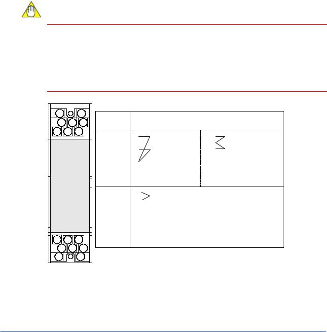
3.1External Wiring
(a)All cable ends must furnished with crimp-on type solderless lugs (for 4mm screws).
(b)Draw out the internal unit from the rack case.
(c)Connect the cables to the correct terminals referring to Figure 3-1.
(d)Return the internal unit into the rack case after completing the wiring.
(e)Always return the terminal block cover to its original position after completing the wiring.
NOTE
•Contacts have positive/negative minus polarity. Take care not to confuse the polarity when wiring.
•Connect a surge absorber (protective diode, CR circuit, etc.) in parallel to the load.
•Do not connect loads exceeding the rated load.
•The terminal block cover cannot be returned to its original position if the internal unit is not installed correctly inside the rack case.
Securely return the terminal block cover because it also functions as lock for the internal unit.
J |
|
K |
B D H |
||
A C |
F |
|
Front view |
||
may differ |
||
according to |
||
device. |
|
|
1 |
3 |
5 |
2 |
4 |
6 |
7 |
|
8 |
Terminal |
|
|
Description |
|
Designation |
|
|
|
|
A |
- |
SICD drive |
|
Transistor contact-1 |
B |
|
pulse-1 (*1, 3) |
COM |
(*2, 3) |
C |
- |
SICD drive |
Transistor contact-2 |
|
D |
|
pulse-2 (*1, 3) |
|
(*2, 3) |
F |
+ |
|
|
|
H |
|
|
|
|
J |
|
|
|
|
K |
|
|
|
|
1 |
+ |
Input (1 to 5 V DC) |
|
|
2 |
- |
|
||
3 |
|
|
|
|
4 |
|
|
|
|
5 |
|
|
|
|
6 |
|
|
|
|
7 |
|
|
|
|
8 |
|
|
|
|
*1: |
Pulse signals can also be used to drive an electromagnetic counter of rating (24 V DC, 150mA or less). |
*2: |
Transistor contact output can be used to provide a pulse output signal to a computer or used to drive another |
|
counter when combined with an external power supply |
*3 |
If a pulse ON time of 60 ms is required, short terminals A and C. This generates a pulse signal having an ON time of |
|
60 ms across the A/C and F terminals and across the A/C and B terminals. |
*4: |
When a counter other than SICD is used, connect a surge voltage protective diode in parallel with the counter coil. |
Figure 3-1 Terminal Layout and Terminal Wiring
IM 01B04M01-02E 9th Edition : 2004.05.01-00
Loading...