


BATCH CONTROLLERS
MODEL 414A
November 1995
CONTENTS
1. |
Introduction |
3 |
||
|
1.1 |
Model Number Designation |
4 |
|
2. |
Specification |
5 |
||
3. |
Operation |
|
7 |
|
|
3.1 |
Front Panel Operation |
8 |
|
|
3.2 |
Batch Operations |
11 |
|
|
|
3.2.1 |
Control Relay Outputs |
13 |
|
|
3.2.2 |
Signal Timeout |
14 |
|
|
3.2.3 |
End of Batch |
15 |
|
|
3.2.4 |
Auto Restart |
16 |
|
|
3.2.5 |
Automatic Overrun Compensation |
17 |
|
3.3 |
Calculation of Rate and Total |
18 |
|
|
|
3.3.1 |
Analog Input |
18 |
|
|
3.3.2 |
The Cutoff Point |
19 |
|
|
3.3.3 |
Filtering |
20 |
|
3.4 |
Total Conversion |
22 |
|
|
3.5 |
The Output Pulse and Flow Alarm |
23 |
|
4. |
Options |
|
25 |
|
|
4.1 |
The RS232/422/485 Interface Option |
25 |
|
|
|
4.1.1 |
Hardware |
25 |
|
|
4.1.2 |
Multipoint Communication |
26 |
|
|
4.1.3 |
Communication Protocol |
28 |
5. |
Calibration |
30 |
||
|
5.1 |
Programming the Setup Parameters |
32 |
|
|
5.2 |
Entering the Batch Parameters |
34 |
|
|
5.3 |
Programming Options |
36 |
|
|
5.4 |
Checking the Input Signal |
38 |
|
6. |
Input Circuits |
39 |
|
|
6.1 |
The Signal Input |
39 |
|
6.2 |
Remote Switch Inputs |
41 |
7. |
Installation |
42 |
|
|
7.1 |
General |
42 |
|
7.2 |
Wiring Designations for the Model 414A |
44 |
8. |
Trouble Shooting |
45 |
|
|
8.1 |
Error Codes |
47 |
Index |
|
48 |
|

Introduction 3
1. INTRODUCTION
The Model 414A Batch Controller accepts analog flow signals and automatically controls the batching of fluids via a one or two stage control valve.
The instrument is extremely flexible and easy to operate, with a four key, front panel operation that enables the batch quantity to be set, and batches to be started or stopped.
The Batch Controller is a microprocessor based instrument which measures 4-20mA, 0-20mA, 1-5 Volt or 0-10 Volt signals from flowmeters and pressure transducers. The instrument can be programmed to display directly in engineering units and includes such features as linear or square law calculation, integration and digital filtering.
The 4-20mA, 0-20mA, 1-5 Volt and 0-10 Volt input signals are isolated from the supply rails and outputs, and may therefore float independently. This ensures that the input will be compatible with all transmitters and can be used in current loops which have more than one receiver.
The instrument is fully programmable, with all calculation constants set via the front panel switches and stored in a non-volatile memory which will retain data indefinitely. The user can program such parameters as span, zero, filtering levels, display resolution and cutoff points.
This instrument conforms to the EMC-Directive of the Council of European Communities 89/336/EEC and the following standards:
Generic Emission Standard EN 50081-1 |
Residential, Commercial & Light |
|
Industry Environment. |
Generic Emission Standard EN 50081-2 |
Industrial Environment. |
Generic Immunity Standard EN 50082-1 |
Residential, Commercial & Light |
|
Industry Environment. |
Generic Immunity Standard EN 50082-2 |
Industrial Environment. |
In order to comply with these standards, the wiring instructions in Section 8.1 must be followed.

4 Introduction
1.1 MODEL NUMBER DESIGNATION
The Model number of an instrument describes which input and output options are installed and the AC mains voltage rating.
Model 414 A. 1 0 E B
B for Backlite
C for Conformal Coating
E for 220/240 VAC
A for 110/120 VAC
D for DC Power Only
Options
0 for no option
2 for RS232/422/485
Mounting
1 for panel mounting
2 for field mounting
3 for explosionproof
The Model Number of the instrument is displayed on first entering the Calibration Mode (see Section 5).
|
Specification 5 |
2. SPECIFICATION |
|
General |
|
Display: |
6 digit LCD. 0.7" (17.8mm) high digits. |
Display Update Rate: |
0.25 seconds. |
Transducer Supply: |
8-24VDC field adjustable. |
|
50mA maximum. |
Power Requirements: |
11.5 to 28.5 volts DC. |
|
130 mA typical current (no options). |
|
AC Mains: Set internally to 95-135 VAC or |
|
190-260 VAC. |
Operating Temperature: |
0 to 55°C standard. |
Dimensions: |
5.7" (144mm) wide x 2.8" (72mm) high x |
|
7.0" (178mm) deep. |
Cutout: |
5.5" (139mm) wide x 2.6" (67mm) high. |
Analog Input |
|
Input: |
4-20mA, 0-20mA, 1-5 Volt or 0-10 Volt. |
|
The input circuit is floating and isolated from |
|
the power supply and outputs. |
Span: |
0.1000 to 50000.0000. |
Zone: |
0.0000 to 50000.0000. |
Accuracy: |
0.075% of full scale. |
Self-Calibrating: |
An internal reference is sampled every 10 |
|
minutes. Temp Co-efficient is 40ppm/C. |
|
Aging is 20ppm/1000 hrs. |
Integration: |
The rate is integrated with a timebase |
|
selectable to be in days, hours, minutes or |
|
seconds. |
Cut-off: |
A cut-off point can be set below which the |
|
rate is not integrated. |
6 Specification
Relay Outputs
Maximum Switching Power: 1250VA.
Maximum Switching Voltage: 250VAC, 30VDC.
Maximum Switching Current: 5 Amps.
Pulse Output |
|
Pulse Width: |
10mSec (negative going pulse). |
Maximum Duty Cycle: |
49 pulses per second. |
Output: |
An open collector transistor will sink |
|
100mA. |
Scaling: |
The pulse output is scaled and outputs one |
|
pulse each time the accumulated total |
|
increments. |
Operation 7
3. OPERATION
The Model 414A Batch Controller uses a low power CMOS microprocessor to perform all control functions and calculations.
The instrument is fully programmable with all operating parameters and calculation constants user programmable. (See Section 5 entitled "Calibration" for information on programming.) All parameters and constants are stored in a non-volatile memory which retains data without battery backup for a minimum of 10 years.
A block diagram of the instrument is shown below.
4-20mA |
|
|
|
|
RS232/422 |
|
|
|
|
|
||||||
(0-20mA) |
|
|
|
|
|
|
|
|
|
RS232/422 |
||||||
|
|
|
|
|
Option |
|
|
|
|
|||||||
Signal |
|
|
|
|
|
|
|
|
Output |
|||||||
|
|
|
|
|
|
|
|
|
|
|
|
|
|
|||
Common |
|
|
|
|
|
|
|
|
|
|
|
|
|
|
EOB |
|
|
|
|
|
|
|
|
|
|
|
|
|
|
|
|||
0-10 V |
|
|
|
|
|
|
|
|
|
|
|
|
|
|
|
|
|
|
|
|
|
|
|
|
|
|
|
|
|
|
|
||
|
|
|
|
|
|
|
|
|
|
|
|
|
|
|
Control |
|
|
|
|
|
|
|
|
|
|
|
|
|
|
|
|
||
1-5 V |
|
|
|
|
|
Relays |
|
|
|
|
||||||
|
|
|
|
|
|
|
|
|
Relay Outputs (2) |
|||||||
|
|
|
|
|
|
|
|
|
|
|
|
|
|
|
|
|
|
|
|
|
|
|
|
|
|
|
|
|
|
|
|
|
Pulse |
|
|
|
|
|
|
|
|
|
|
|
|
|
|
|
|
Output |
|
|
|
|
Model 414A |
|
|
|
|
Flow Alarm |
|||||||
|
|
|
|
|
|
|||||||||||
|
|
|
|
|
|
|
|
|
|
|
|
|
DC Input Power |
|||
|
|
|
|
|
|
|
|
|
|
|
|
|
||||
|
|
|
|
|
|
|
|
|
|
|
|
|
||||
|
|
|
|
|
|
|
|
|
|
|
|
|
||||
|
|
|
|
110/220V |
|
|
|
|
|
DC Power Ground |
||||||
|
|
|
|
|
|
|
|
|
||||||||
|
|
|
|
AC Mains |
|
|
|
|
|
|
DC Power Output to Sensors |
|||||
|
|
|
|
|
|
|
|
|
|
|
|
|
||||

8 Operation
3.1 FRONT PANEL OPERATION
The four key operation of the Batch Controller is straight forward.
SETTING THE BATCH QUANTITY
The Batch quantity is programmed as follows:
Switch Action |
Display |
Comments |
Press BATCH SET |
Batch |
"Batch" is displayed for one second |
|
|
followed by the batch quantity last |
|
|
entered. The Batch Set LED lights. |
|
"1" 2345 |
Press |
"2" 2345 |
The most significant digit flashes indicating that it can be changed.
Pressing the DISPLAY key will increment the digit. (The up arrow on the Display key indicates to increment digit.)
Press |
2 "2" 345 Pressing the RUN key will change digit |
||
|
|
and enables the next digit to be |
|
|
|
incremented. (The right arrow on the |
|
|
|
RUN key indicates to change digit.) |
|
Press BATCH SET |
Set |
Once the desired number |
is entered, |
|
|
press the BATCH SET key |
to return to |
|
|
the Run mode. The Batch Set LED will |
|
|
|
extinguish. |
|
Once programmed, the Batch quantity will be retained in the non-volatile memory and will not alter until changed by the user.
Operation 9
The Batch quantity can only be set while the instrument is in non-operational state such as when the batch is complete, or if the batch process has been interrupted. However, the Batch key can be pressed while in the run state and the Batch quantity checked. All digits will flash to signal the quantity cannot be changed.
STARTING A BATCH
To start the process the RUN key is pressed. The Run LED will light and the instrument will begin to totalise from zero or, if programmed for the count down mode, the display will decrement from the batch quantity.
The batcher has two output relays and these are energised and de-energised as described in section 3.2.
STOPPING
The process can be stopped at any time by pressing the STOP switch. Once the process has been interrupted in this way it can be continued by pressing the RUN switch or the process can be aborted and the instrument reset by pressing the STOP switch a second time.
When the process is interrupted, the STOP LED will flash to prompt the operator to either restart or abort the batch.
RESETTING
The instrument can be programmed to reset in one of two ways.
At the end of a batch, the STOP key must be pressed to reset the Batch Total. If the instrument is programmed to count down, the Batch Total will then revert to the preset quantity. If it is programmed to count up, the Batch Total will clear to zero.
If Auto Reset is programmed, the Batch Total will automatically reset when the RUN key is pressed and then commence the next batch.
10 Operation
DISPLAYED INFORMATION
The display will normally show the Batch Total, which is the total count for the current batch and is reset on each new batch.
The DISPLAY key can be used to display the following additional information:
Rate
On the first press of the DISPLAY key, the display shows RATE for one second followed by the flowrate.
Accumulated Total
On the next press of the DISPLAY key, the display shows ACC for one second followed by the actual total. The Accumulated Total cannot be reset during normal operation.
LIMIT ON BATCH SIZE
To prevent accidental entry of large batch quantities, a maximum batch limit can be programmed during calibration. The operator is then prevented from entering a batch quantity which exceeds this value.

Operation 11
3.2 BATCH OPERATIONS
The Batch Control functions can be programmed, during Calibration, to operate in one of two ways.
1.At the end of the batch, the STOP key must be pressed to reset the Batch Total. (This must be done before another batch can be started.)
|
PAUSE |
Batch |
|
|
Quantity |
||
Run |
Stop Run |
||
Reached Stop Run |
Count Down
Count Up
Relay 1
Relay 2
Start Time |
Prestop |
|
|
|
|||
Quantity |
|||
|
|||
End of
Batch
End of Batch
12 Operation
2.If Automatic Reset is programmed, a new batch is commenced each time the RUN key is pressed.
|
|
|
|
|
|
PAUSE |
Batch |
|
|
|
|
|
|
|
|
|
|
|
|
||||||||||
|
|
|
|
|
|
Quantity |
|
|
|
|
|
|
|
|
|
|
|
|
|||||||||||
|
|
|
Run |
Stop Run |
|
|
|
|
|
|
|
|
|
|
|
|
|||||||||||||
|
|
|
Reached |
|
|
|
|
|
|
|
|
|
Run |
||||||||||||||||
|
|
|
|
|
|
Count Down |
|
|
|
|
|
|
|
|
|
|
|
|
|
|
|
|
|
||||||
|
|
|
|
|
|
|
|
|
|
|
|
|
|
|
|
|
|
|
|
|
|
|
|||||||
|
|
|
|
|
|
|
|
|
|
|
|
|
|
|
|
|
|
|
|
|
|
|
|
|
|
|
|
||
|
|
|
|
|
|
|
|
|
|
|
|
|
|
|
|
|
|
|
|
|
|
|
|
|
|
|
|
|
|
|
|
|
|
|
|
Count Up |
|
|
|
|
|
|
|
|
|
|
|
|
|
|
|
|
|
||||||
Relay 1 |
|
|
|
|
|
|
|
|
|
|
|
|
|
|
|
|
|
||||||||||||
|
|
|
|
|
|
|
|
|
|
|
|
|
|
|
|
|
|
|
|
|
|
|
|
||||||
|
|
|
|
|
|
|
|
|
|
|
|
|
|
|
|
|
|
|
|
|
|
|
|
|
|
|
|
|
|
Relay 2
Start Time |
Prestop |
|
|
|
|
|
|
|
|
|
|
Quantity |
|
|
|
|
|
Auto Restart |
|||
|
|
|
|
|
|
|
|
|
|
Time |
End of
Batch
End of Batch
The Batch Controller can also be programmed, during Calibration, to either count up from zero on each batch, or to count down from the preset batch quantity.

Operation 13
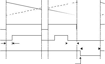
3.2.1 Control Relay Outputs
The two output relays can be set up to control a single valve or a dual valve with slow stop and/or slow start. Alternatively, the second relay can be used to control a pump.
The relay operation is shown on the previous two pages.
A time delay between the Start and the time when relay 2 energises can be programmed to provide a soft startup. The delay can range from 0 (no delay) to 79 minutes and 59 seconds.
A Prestop quantity (ie. the quantity to the end of the batch) can also be programmed to provide a slowdown of flow at the end of the batch, thereby enabling precise quantities to be batched.
The process can be stopped at any time by pressing the STOP key, whereby both relays will immediately de-energise. The process can then be aborted and the batcher reset by pressing the STOP key again, or the process continued by pressing the RUN key.
If the process is continued and the instrument was previously in the slow start or main control phases (ie. not the prestop phase), the timer will be reset and a slow start will occur with a full time delay to ensure a correct start up. The totals will not be reset and the batch quantity will remain unchanged.

14 Operation
3.2.2 Signal Timeout
The Signal Timeout period defines a time interval which is used to detect if the flow has stopped. If there is no signal input for a time greater than the Signal Timeout period, the flow is deemed to have stopped. A Signal Timeout period has two functions:
To detect the loss of signal midway through a batch when the relays are energised. In this case, the Batcher will enter a Flow Alarm condition and de-energise the relays.
After the preset batch quantity has been reached and the relays de-energised, some overrun of flow may occur due to slow valve closure, etc. In this case, the Signal Timeout is used to determine when the flow has ceased and thereby accurately determine the amount of overrun.
The instrument enables the user to program a time interval of up to 99 seconds to detect an absence of signal input. If the Signal Timeout is set to 0, this function is disabled.
Flow Alarm
If the Signal Timeout is set at greater than 0, and loss of signal is detected midway through a batch, a Flow Alarm signal is output on terminal 7. In addition, both relays are de-energised. The Flow Alarm output and condition is maintained until acknowledged by pressing the STOP switch. The alarm condition is also signalled to the operator by the flashing STOP LED. Once acknowledged, process can then be reset via the STOP switch or continued by pressing the RUN key.
 Loading...