


 Loading...
User’s
Manual YVP110
Advanced Valve Positioner
IM 21B04C01-01E
IM 21B04C01-01E
10th Edition

i
YVP110
Advanced Valve Positioner
|
|
|
IM 21B04C01-01E 10th Edition |
|
CONTENTS |
|
|
||
Introduction........................................................................................................... |
|
|
viii |
|
|
|
■ Notes on the User’s Manual.............................................................................. |
viii |
|
|
|
■ For Safe Use of Product.................................................................................... |
viii |
|
|
|
■ Warranty.............................................................................................................. |
ix |
|
|
|
■ Trade Mark........................................................................................................... |
ix |
|
|
|
■ATEX Documentation........................................................................................... |
x |
|
PART I: HARDWARE |
|
|||
1. |
Notes on Handling.................................................................................... |
1-1 |
||
|
1.1 |
Nameplate........................................................................................................... |
1-1 |
|
|
1.2 |
Transport............................................................................................................ |
|
1-1 |
|
1.3 |
Storage................................................................................................................ |
|
1-1 |
|
1.4 |
Choosing the Installation Location................................................................. |
1-1 |
|
|
1.5 |
Use of a Transceiver.......................................................................................... |
1-1 |
|
|
1.6 |
Insulation Resistance Test and Withstand Voltage Test............................... |
1-2 |
|
|
1.7 |
Notes for Saftey................................................................................................. |
1-2 |
|
|
1.8 |
EMC Conformity Standards............................................................................. |
1-3 |
|
|
1.9 |
Installation of Explosion Protected Type Positioner..................................... |
1-3 |
|
|
|
1.9.1 |
FM Certification.................................................................................. |
1-3 |
|
|
1.9.2 |
ATEX Certification.............................................................................. |
1-7 |
|
|
1.9.3 |
CSACertification.............................................................................. |
1-12 |
|
|
1.9.4 |
TIIS Certification............................................................................... |
1-12 |
2. |
Part Names................................................................................................ |
|
2-1 |
|
|
2.1 |
Appearance and Part Names............................................................................ |
2-1 |
|
|
2.2 |
Block Diagram.................................................................................................... |
2-1 |
|
3. |
Installing YVP110 onActuator................................................................. |
3-1 |
||
|
3.1 |
General................................................................................................................ |
|
3-1 |
|
3.2 |
Installing YVP110 onActuator.......................................................................... |
3-1 |
|
|
|
3.2.1 |
Installing YVP110 on Linear-motion Control Valve............................. |
3-1 |
|
|
3.2.2 |
Installing YVP110 on Rotary-motion Control Valve............................ |
3-3 |
|
|
3.2.3 |
A/M Switching..................................................................................... |
3-5 |
10th Edition: Dec. 2013 (YK) |
IM 21B04C01-01E |
All Rights Reserved, Copyright © 2000, Yokogawa Electric Corporation |
|

ii
4. |
Wiring and Piping...................................................................................... |
4-1 |
||
|
4.1 |
General................................................................................................................ |
|
4-1 |
|
4.2 |
Piping.................................................................................................................. |
|
4-1 |
|
|
4.2.1 |
Air Supply........................................................................................... |
4-1 |
|
|
4.2.2 |
Pneumatic Piping................................................................................ |
4-1 |
|
4.3 |
Wiring.................................................................................................................. |
|
4-2 |
|
|
4.3.1 |
Recommended Cables....................................................................... |
4-2 |
|
|
4.3.2 |
Precautions on Wiring........................................................................ |
4-2 |
|
4.4 |
Grounding.......................................................................................................... |
4-4 |
|
5. |
Setup.......................................................................................................... |
|
|
5-1 |
|
5.1 |
General................................................................................................................ |
|
5-1 |
|
5.2 |
Setting Basic Parameters................................................................................. |
5-1 |
|
|
5.3 |
Carrying out Tuning .......................................................................................... |
5-2 |
|
|
5.4 |
Checking ValveActions.................................................................................... |
5-4 |
|
|
5.5 |
Setting Parameters of Transducer Block........................................................ |
5-4 |
|
6. |
Maintenance.............................................................................................. |
|
6-1 |
|
|
6.1 |
General................................................................................................................ |
|
6-1 |
|
6.2 |
Periodic Inspections......................................................................................... |
6-1 |
|
|
|
6.2.1 |
Cleaning the Fixed Nozzle................................................................. |
6-1 |
|
6.3 |
Part Replacement.............................................................................................. |
6-2 |
|
|
|
6.3.1 |
Replacing the Control RelayAssembly.............................................. |
6-2 |
|
|
6.3.2 |
Replacing the Screen Filters ............................................................. |
6-2 |
|
|
6.3.3 |
Replacing the InternalAir Filter.......................................................... |
6-2 |
|
|
6.3.4 |
Tuning the Pressure Balance of Control Relay.................................. |
6-3 |
7. |
Standard Specifications........................................................................... |
7-1 |
||
PART II: FUNCTIONS
8. |
About Fieldbus.......................................................................................... |
|
8-1 |
|
|
8.1 |
Outline................................................................................................................. |
|
8-1 |
|
8.2 |
Internal Structure of YVP110............................................................................ |
8-1 |
|
|
|
8.2.1 |
System/network Management VFD................................................... |
8-1 |
|
|
8.2.2 |
Function Block VFD............................................................................ |
8-1 |
|
8.3 |
Logical Structure of Each Block...................................................................... |
8-1 |
|
|
8.4 |
System Configuration....................................................................................... |
8-1 |
|
|
|
8.4.1 |
Connection of Devices....................................................................... |
8-2 |
|
8.5 |
Integration of DD................................................................................................ |
8-2 |
|
9. |
Configuration............................................................................................ |
|
9-1 |
|
|
9.1 |
Network Design................................................................................................. |
9-1 |
|
|
9.2 |
Network Definition............................................................................................. |
9-1 |
|
|
9.3 |
Definition of Combining Function Blocks...................................................... |
9-2 |
|
IM 21B04C01-01E

iii
|
9.4 |
Setting of Tags andAddresses........................................................................ |
9-3 |
|
|
9.5 |
Communication Setting.................................................................................... |
9-4 |
|
|
|
9.5.1 |
VCR Setting ........................................................................................ |
9-4 |
|
|
9.5.2 |
Function Block Execution Control . ..................................................... |
9-4 |
|
9.6 |
Block Setting...................................................................................................... |
9-5 |
|
|
|
9.6.1 |
Link Object .......................................................................................... |
9-5 |
|
|
9.6.2 |
Trend Object ....................................................................................... |
9-5 |
|
|
9.6.3 |
View Object ......................................................................................... |
9-5 |
|
|
9.6.4 |
Function Block Parameters .............................................................. |
9-12 |
10. Actions of YVP110 During Operation................................................... |
10-1 |
|||
|
10.1 |
Block Modes..................................................................................................... |
10-1 |
|
|
10.2 |
Alarm Generation............................................................................................ |
10-2 |
|
|
10.3 |
Simulation Function........................................................................................ |
10-3 |
|
11. |
Resource Block ...................................................................................... |
11-1 |
||
|
11.1 |
General |
............................................................................................................. |
11-1 |
|
11.2 |
Alarm Processing ........................................................................................... |
11-1 |
|
|
11.3 |
Device Status .................................................................................................. |
11-1 |
|
12. |
Transducer Block.................................................................................... |
12-1 |
||
|
12.1 |
General.............................................................................................................. |
|
12-1 |
|
12.2 |
Forward ....................................................................................................Path |
12-1 |
|
|
|
12.2.1 .......................................................................... |
Input from AO Block |
12-1 |
|
|
12.2.2 ............................. |
Position - to - flow Rate Characteristic Conversion |
12-2 |
|
|
12.2.3 ............................................................... |
FINAL _ VALUE and Range |
12-2 |
|
|
12.2.4 ...................................................... |
Tight - shut and Full - open Actions |
12-2 |
|
12.3 |
Backward .................................................................................................Path |
12-2 |
|
|
|
12.3.1 .............................................................. |
FINAL _ POSITION _ VALUE |
12-2 |
|
|
12.3.2 ................................................................................... |
Limit Switches |
12-2 |
|
12.4 |
Auto Tuning...................................................................................................... |
12-3 |
|
|
12.5 |
Travel Calibration............................................................................................. |
12-4 |
|
|
12.6 |
Online Diagnostics.......................................................................................... |
12-4 |
|
|
|
12.6.1 ..................................................................................... |
XD _ ERROR |
12-4 |
|
|
12.6.2 ................................................................................. |
Fail - safe Action |
12-5 |
|
|
12.6.3 ........................................................... |
Operation Result Integration |
12-5 |
|
|
12.6.4 .................................................................... |
Recording of Revisions |
12-5 |
|
12.7 |
Control .........................................................................................Parameters |
12-5 |
|
|
12.8 |
Temperature ....................................................and Pressure Measurement |
12-5 |
|
13. |
AO Function Block.................................................................................. |
13-1 |
||
|
13.1 |
General.............................................................................................................. |
|
13-1 |
|
13.2 |
Modes................................................................................................................ |
|
13-1 |
|
13.3 |
Forward ....................................................................................................Path |
13-1 |
|
|
|
13.3.1 ......................................................................................... |
Fault state |
13-1 |
|
13.4 |
Backward .................................................................................................Path |
13-2 |
|
IM 21B04C01-01E

iv
|
13.5 |
IO_OPTS and STATUS_OPTS........................................................................ |
13-2 |
|
|
13.6 |
Mode Shedding upon Computer Failure ...................................................... |
13-3 |
|
|
13.7 |
Initialization at Start......................................................................................... |
13-3 |
|
|
13.8 |
Alarm Processing ........................................................................................... |
13-3 |
|
14. |
DI Function Block................................................................................... |
14-1 |
||
|
14.1 |
General.............................................................................................................. |
|
14-1 |
|
14.2 |
Modes................................................................................................................ |
|
14-1 |
|
14.3 |
PV Value (PV_D)............................................................................................... |
14-1 |
|
|
14.4 |
Filtering............................................................................................................. |
|
14-1 |
|
14.5 |
Output............................................................................................................... |
|
14-2 |
|
14.6 |
IO_OPTS and STATUS_OPTS........................................................................ |
14-2 |
|
|
14.7 |
Alarm Processing ........................................................................................... |
14-2 |
|
|
|
14.7.1 |
BlockAlarms..................................................................................... |
14-2 |
|
|
14.7.2 |
DiscreteAlarm.................................................................................. |
14-2 |
15. |
OS Function Block.................................................................................. |
15-1 |
||
|
15.1 |
General.............................................................................................................. |
|
15-1 |
|
15.2 |
Modes................................................................................................................ |
|
15-1 |
|
15.3 |
Output Processing.......................................................................................... |
15-1 |
|
|
15.4 |
Backward Path (BKCAL_OUT) ...................................................................... |
15-2 |
|
|
15.5 |
STATUS_OPTS ................................................................................................ |
15-2 |
|
|
15.6 |
Alarm Processing ........................................................................................... |
15-2 |
|
16. |
PID Function Block................................................................................. |
16-1 |
||
|
16.1 |
General.............................................................................................................. |
|
16-1 |
|
16.2 |
Modes................................................................................................................ |
|
16-1 |
|
16.3 |
Input Processing............................................................................................. |
16-1 |
|
|
16.4 |
Setpoint (SP) Limiters..................................................................................... |
16-1 |
|
|
16.5 |
PID Computation............................................................................................. |
16-2 |
|
|
16.6 |
Control Output................................................................................................. |
16-2 |
|
|
16.7 |
Direction of ControlAction............................................................................. |
16-2 |
|
|
16.8 |
ControlAction Bypass.................................................................................... |
16-2 |
|
|
16.9 |
Feed-forward.................................................................................................... |
16-3 |
|
|
16.10 |
External-output Tracking (LO)........................................................................ |
16-3 |
|
|
16.11 |
Measured-value Tracking............................................................................... |
16-3 |
|
|
16.12 |
CONTROL_OPTS............................................................................................. |
16-3 |
|
|
16.13 |
Initialization and Manual Fallback (IMan)...................................................... |
16-4 |
|
|
16.14 |
Manual Fallback............................................................................................... |
16-4 |
|
|
|
16.14.1 |
STATUS_OPTS................................................................................ |
16-4 |
|
16.15 |
Auto Fallback................................................................................................... |
16-4 |
|
|
16.16 |
Mode Shedding upon Computer Failure....................................................... |
16-4 |
|
|
16.17 |
Alarms............................................................................................................... |
|
16-5 |
|
|
16.17.1 |
BlockAlarm (BLOCK_ALM)............................................................. |
16-5 |
|
|
16.17.2 |
ProcessAlarms................................................................................. |
16-5 |
IM 21B04C01-01E

v
17. |
IS Function Block.................................................................................... |
17-1 |
||
|
17.1 |
IS Function Block Schematic......................................................................... |
17-1 |
|
|
17.2 |
Input Section ................................................................................................... |
17-3 |
|
|
|
17.2.1 |
Mode Handling ................................................................................ |
17-3 |
|
|
17.2.2 |
MIN_GOOD Handling ...................................................................... |
17-3 |
|
17.3 |
Selection |
.......................................................................................................... |
17-4 |
|
|
17.3.1 |
OP_SELECT Handling .................................................................... |
17-4 |
|
|
17.3.2 |
SELECTION Handling ..................................................................... |
17-5 |
|
17.4 |
Output Processing ....................................................................................... |
17-11 |
|
|
|
17.4.1 |
Handling of SELECTED ................................................................ |
17-11 |
|
|
17.4.2 |
OUT Processing ............................................................................ |
17-12 |
|
|
17.4.3 |
STATUS_OPTS ............................................................................. |
17-13 |
|
17.5 |
Application Example .................................................................................... |
17-13 |
|
18. |
AR Function Block.................................................................................. |
18-1 |
||
|
18.1 |
AR Function Block Schematic....................................................................... |
18-1 |
|
|
18.2 |
Input Section ................................................................................................... |
18-2 |
|
|
|
18.2.1 |
Main Inputs ...................................................................................... |
18-2 |
|
|
18.2.2 |
Auxiliary Inputs ................................................................................ |
18-2 |
|
|
18.2.3 |
INPUT_OPTS .................................................................................. |
18-3 |
|
|
18.2.4 |
Relationship between the Main Inputs and PV ............................... |
18-3 |
|
18.3 |
Computation Section ..................................................................................... |
18-3 |
|
|
|
18.3.1 |
Computing Equations ...................................................................... |
18-3 |
|
|
18.3.2 |
Compensated Values ...................................................................... |
18-4 |
|
|
18.3.3 |
Average Calculation ........................................................................ |
18-4 |
|
18.4 |
Output Section ................................................................................................ |
18-4 |
|
|
|
18.4.1 |
Mode Handling ................................................................................ |
18-4 |
|
|
18.4.2 |
Status Handling ............................................................................... |
18-5 |
19. |
Diagnostics.............................................................................................. |
|
19-1 |
|
|
19.1 |
Overview........................................................................................................... |
|
19-1 |
|
19.2 |
Integration Functions...................................................................................... |
19-1 |
|
|
19.3 |
Signature Measurement Functions............................................................... |
19-2 |
|
|
|
19.3.1 |
Signature Measurement Procedure................................................. |
19-2 |
|
|
19.3.2 |
Signatures and Relevant Parameters.............................................. |
19-3 |
|
|
19.3.3 |
Signature Measuring Result............................................................. |
19-4 |
20. |
Troubleshooting...................................................................................... |
20-1 |
||
|
20.1 |
What to Do First............................................................................................... |
20-1 |
|
|
20.2 |
Troubleshooting Communications............................................................... |
20-1 |
|
|
20.3 |
Troubleshooting Function Block Parameters.............................................. |
20-1 |
|
|
20.4 |
Troubleshooting Valve Control...................................................................... |
20-2 |
|
|
20.5 |
TroubleshootingAuto Tuning........................................................................ |
20-3 |
|
|
20.6 |
Troubleshooting Position, Pressure, and Temperature Sensors.............. |
20-3 |
|
IM 21B04C01-01E

vi
Appendix 1. Function Block Parameters....................................................... |
A-1 |
||
A1.1 |
Parameters of Resource Block....................................................................... |
A-1 |
|
A1.2 |
Parameters of Transducer Block ................................................................... |
A-3 |
|
A1.3 |
Parameters ofAO Block .................................................................................. |
A-8 |
|
A1.4 |
Parameters of DI Block ................................................................................. |
A-10 |
|
A1.5 |
Parameters of OS Block ................................................................................. |
A-11 |
|
A1.6 |
Parameters of PID Block (Optional) ............................................................. |
A-12 |
|
A1.7 |
Parameters of IS Block.................................................................................. |
A-14 |
|
A1.8 |
Parameters ofAR Block................................................................................. |
A-16 |
|
A1.9 |
IO_OPTS -Availability of Options for Each Block ...................................... |
A-18 |
|
A1.10 |
STATUS_OPTS -Availability of Options for Each Block ........................... |
A-18 |
|
A1.11 |
CONTROL_OPTS -Availability of Options for Each Block ....................... |
A-18 |
|
Appendix 2. Link Master Functions............................................................. |
A-19 |
||
A2.1 |
LinkActive Scheduler.................................................................................... |
A-19 |
|
A2.2 |
Link Master...................................................................................................... |
A-19 |
|
A2.3 |
Transfer of LAS............................................................................................... |
A-19 |
|
A2.4 |
LM Functions.................................................................................................. |
A-20 |
|
A2.5 |
LM Parameters................................................................................................ |
A-21 |
|
|
A2.5.1 |
LM Parameter List............................................................................ |
A-21 |
|
A2.5.2 Descriptions for LM Parameters....................................................... |
A-22 |
|
A2.6 |
FAQs................................................................................................................. |
|
A-25 |
Appendix 3. DD Methods and DD Menu....................................................... |
A-26 |
||
A3.1 |
Overview.......................................................................................................... |
|
A-26 |
A3.2 |
DD Methods .................................................................................................... |
A-26 |
|
|
A3.2.1 |
Transducer Block.............................................................................. |
A-26 |
|
A3.2.2 |
AO Block........................................................................................... |
A-28 |
|
A3.2.3 |
OS Block........................................................................................... |
A-29 |
Appendix 4. |
Software Download.................................................................. |
A-30 |
|
A4.1 |
Benefits of Software Download.................................................................... |
A-30 |
|
A4.2 |
Specifications................................................................................................. |
A-30 |
|
A4.3 |
Preparations for Software Downloading..................................................... |
A-30 |
|
A4.4 |
Software Download Sequence...................................................................... |
A-30 |
|
A4.5 |
Download Files............................................................................................... |
A-31 |
|
A4.6 |
Steps afterActivating a Field Device............................................................ |
A-31 |
|
A4.7 |
Troubleshooting............................................................................................. |
A-32 |
|
A4.8 |
Resource Block’s Parameters Relating to Software Download................ |
A-32 |
|
A4.9 |
System/Network Management VFD Parameters Relating to Software |
A-34 |
|
|
Download......................................................................................................... |
||
A4.10 |
Comments on System/Network Management VFD Parameters Relating to |
||
|
Software Download........................................................................................ |
A-35 |
|
Appendix 5. PositionAdjustment of Feedback Lever................................ |
A-37 |
||
IM 21B04C01-01E

|
|
vii |
|
|
|
Appendix 6. Manual Tuning Guideline......................................................... |
A-38 |
|
A6.1 |
General............................................................................................................. |
A-38 |
A6.2 |
Control Parameter Tuning Procedure.......................................................... |
A-38 |
A6.3 |
Examples of Tuning Control Parameters..................................................... |
A-40 |
A6.4 |
Description of Control Parameters............................................................... |
A-41 |
Installation and Operating Precautions for TIIS Flameproof Equipment |
||
.............................................................................................................. |
|
EX-B03 |
Customer Maintenance Parts List |
|
|
YVP110Advanced Valve Positioner................................................ |
CMPL21B04C01-01E |
|
Revision Record |
|
|
IM 21B04C01-01E

<Introduction> viii
Introduction
The YVP110 advanced valve positioner is fully factory-tested according to the specifications indicated upon the order.
This User’s Manual consists of two parts: Hardware and Functions. The Hardware part gives instructions on handling, wiring set-up and maintenance of YVP110, and the Functions part describes the software functions of YVP110.
In order for the YVP110 to be fully functional and to operate in an efficient manner, both parts in this manual must be carefully read, so that users become familiar with the functions, operation, and handling of the YVP110.
■Notes on the User’s Manual
•This manual should be delivered to the end user.
•The information contained in this manual is subject to change without prior notice.
•The information contained in this manual, in whole or part, shall not be transcribed or copied without notice.
•In no case does this manual guarantee the merchantability of the instrument or its adaptability to a specific client need.
•Should any doubt or error be found in this manual, submit inquiries to your local dealer.
•No special specifications are contained in this manual.
•Changes to specifications, structure, and components used may not lead to the revision of this manual unless such changes affect the function and performance of the instrument.
•Some of the diagrams in this instruction manual are partially omitted, described in writing, or simplified for ease of explanation. The drawings contained in the instruction manual may have a position or characters (upper/lower case) that differ slightly from the what are actually seen to an extent that does not hinder the understanding of functions or monitoring of operation.
•Symbols used in this manual
 WARNING
Contains precautions to protect against the chance of explosion or electric shock which, if not observed, could lead to death or serious injury.
 CAUTION
Contains precautions to protect against danger, which, if not observed, could lead to personal injury or damage to the instrument.
 IMPORTANT
Contains precautions to be observed to protect against adverse conditions that may lead to damage to the instrument or a system failure.
 NOTE
NOTE
Contains precautions to be observed with regard to understanding operation and functions.
■ For Safe Use of Product
For the protection and safety of the operator and the instrument or the system including the
instrument, please be sure to follow the instructions on safety described in this manual when handling this instrument. In case the instrument is handled in contradiction to these instructions, Yokogawa does not guarantee safety. Yokogawa will not be liable for malfunctions or damage resulting from any modification made to this instrument by the customer. Please give your highest attention to the followings.
(a) Installation
•The instrument must be installed by an expert engineer or skilled personnel. The procedures described about INSTALLATION are not permitted for operators.
IM 21B04C01-01E

<Introduction> ix
•Some of the operations will stroke the valve. Keep clear of the valve while the positioner is pneumatically or electrically supplied, so as not to be hit by unexpected movements of the valve.
•In case where ambient temperature is high, care should be taken not to burn yourself, because the surface of the body of the instrument reaches a high temperature.
•All installation shall comply with local installation requirement and local electrical codes.
•Do not supply air at a pressure exceeding the maximum rated air supply pressure. Doing so may result in a high risk of damage or cause an accident.
•To avoid injury or the process being affected when installing or replacing a positioner on a control valve, ensure that;
1)All inputs to the valve actuator and other accessories of the valve and actuator, including air supply and electrical signal, are cut off;
2)The process has been shut down or the control valve is isolated from the process by using bypass valves or the like; and
3)No pressure remains in the valve actuator.
•Auto-Manual switch must not be moved by anyone except for the authorized engineer.
(b) Wiring
•The instrument must be installed by an expert engineer or skilled personnel. The procedures described about WIRING are not permitted for operators.
•Please confirm voltages between the power supply and the instrument before connecting the power cables and that the cables are not powered before connecting.
(c) Operation
•Wait three minutes after power is turned off, before opening the covers.
(d) Maintenance
•Only the procedures written in maintenance descriptions are allowed for users. When further maintenance is needed, please contact nearest YOKOGAWAoffice.
•Care should be taken to prevent the build up of drift, dust or other material on the data plate. In case of its maintenance, use clean, soft and dry cloth.
•The instrument modification or parts
replacement for explosion-protected type instruments by other than authorized representative of Yokogawa Electric Corporation is prohibited and will void the approval.
■Warranty
•The warranty period of the instrument is written on the estimate sheet that is included with your purchase.Any trouble arising during the warranty period shall be repaired free of charge.
•Inquiries with regard to problems with the instrument shall be accepted by the sales outlet or our local dealer representative.
•Should the instrument be found to be defective, inform us of the model name and the serial number of the instrument together with a detailed description of nonconformance and a progress report. Outline drawings or related data will also be helpful for repair.
•Whether or not the defective instrument is repaired free of charge depends on the result of our inspection.
•The following conditions shall not be eligible for charge-exempt repair.
•Problems caused by improper or insufficient maintenance on the part of the customer.
•Trouble or damage caused by mishandling, misusage, or storage that exceeds the design or specification requirements.
•Problems caused by improper installation location or by maintenance conducted in a nonconforming location.
•Trouble or damage was caused by modification or repair that was handled by a party or parties other than our consigned agent.
•Trouble or damage was caused by inappropriate relocation following delivery.
•Trouble or damage was caused by fire, earthquake, wind or flood damage, lightning strikes or other acts of God that are not directly a result of problems with this instrument.
■Trade Mark
•FOUNDATION Fieldbus is a trademark of the Fieldbus Foundation.
•Registered trademarks or trademarks appearing in this manual are not designated by a TM or ® symbol.
•Other company names and product names used in this manual are the registered trademarks or trademarks of their respective owners.
IM 21B04C01-01E

<Introduction>
■ATEX Documentation
This procedure is only applicable to the countries in European Union.
GB |
SK |
CZ
DK
I |
LT |
E |
LV |
EST
NL
PL
SF
SLO
P
H
F
BG
D
RO
S
M
GR
x
IM 21B04C01-01E
<1. Notes on Handling> |
1-1 |
1.Notes on Handling
The YVP110 advanced valve positioner is fully factory-tested upon shipment. When the YVP110 is delivered, visually check that no damage occured during the shipment.
1.1Nameplate
The model name and configuration are indicated on the nameplate. Verify that the configuration indicated in the “Model and Suffix Code” in Chapter 7 is in compliance with the specifications written on the order sheet.
|
|
|
|
|
|
|
|
|
|
|
|
|
|
|
|
|
|
|
|
|
|
|
|
|
|
|
|
|
|
|
|
|
|
|
|
|
|
|
|
|
|
|
|
|
|
|
|
|
|
|
|
|
|
|
|
|
|
|
|
|
|
|
|
|
|
|
|
|
|
|
|
|
|
|
|
|
|
|
|
|
|
|
|
|
|
|
|
|
|
|
|
|
|
|
|
|
|
|
|
|
|
|
|
|
|
|
|
|
|
|
|
|
|
|
|
|
|
|
|
|
|
|
|
|
|
|
|
|
|
|
|
|
|
|
|
|
|
|
|
|
|
|
|
|
|
|
|
|
|
|
|
|
|
|
|
|
|
|
|
|
|
|
|
|
|
|
|
|
|
|
|
F0101.ai |
|||
Figure 1.1 |
Nameplate |
|||||||||
1.2Transport
To prevent damage while in transit, leave the positioner in the original shipping container until it reaches the installation site.
1.3Storage
When an extended storage period is expected, observe the following precautions:
(1)If at all possible, store the positioner in factoryshipped condition, that is, in the original shipping container.
(2)Choose a storage location that satisfies the following requirements.
•Alocation that is not exposed to rain or water.
•Alocation subject to a minimum of vibration or impact.
•The following temperature and humidity range is recommended. Ordinary temperature and humidity (25°C, 65%) are preferable.
Temperature: –40 to 85°C Humidity: 5 to 100% RH (at 40°C)
(3)The performance of the positioner may be impaired if stored in an area exposed to direct rain and water.
To avoid damage to the positioner, install it immediately after removal from the shipping container. Follow wiring instructions in this manual.
1.4Choosing the Installation Location
Although the advanced valve positioner is designed to operate in a vigorous environment, to maintain stability and accuracy, the following is recommended:
(1) Ambient Temperature
It is preferable not to expose the instrument to extreme temperatures or temperature fluctuations. If the instrument is exposed to radiation heat a thermal protection system and appropriate ventilation is recommended.
(2) Environmental Requirements
Do not allow the positioner to be installed in a location that is exposed to corrosive atmospheric conditions. When using the
positioner in a corrosive environment, ensure the location is well ventilated. The unit and its wiring should be protected from exposure to rainwater.
(3) Impact and Vibration
It is recommended that the positioner is installed in a location that is subject to a minimum amount of impact and vibration.
1.5Use of a Transceiver
Although the positioner is designed to resist influence from high frequency noise, use of a transceiver in the vicinity of installation may cause problems. Installing the transmitter in an area free from high frequency noise (RFI) is recommended.
IM 21B04C01-01E

<1. Notes on Handling> |
1-2 |
1.6Insulation Resistance Test and Withstand Voltage Test
 CAUTION
(1)Overvoltage of the test voltage that is so small that it does not cause an dielectric breakdown may in fact deteriorate insulation and lower the safety performance; to prevent this it is recommended that the amount of testing be kept to a minimum.
(2)The voltage for the insulation resistance test must be 500V DC or lower, and the voltage for the withstand voltage test must be 500V AC or lower. Failure to heed these guidelines may cause faulty operation.
(3)Where a built-in arrester is provided (suffix code: /A), the voltage for the insulation resistance test must be 100V DC or lower, and the voltage for the withstand voltage test must be 100VAC or lower. Failure to heed these guidelines may cause faulty operation.
Follow the steps below to perform the test, the wiring of the communication line must be removed before initiating testing.
Insulation resistance test procedure
1.Lay transition wiring between the + terminal and the − terminal.
2.Connect the insulation resistance meter (with the power turned OFF) between the transition wiring of Step 1 above and ground terminal. The polarity of the input terminals must be positive and that of the ground must be negative.
3.Turn the power of the insulation resistance meter ON and measure the insulation resistance. The duration of the applied voltage must be the period during which 100 MΩ
or more is confirmed (or 20 MΩ if the unit is equipped with a built-in arrester).
4.Upon completion of the test, remove the insulation resistance meter, connect a 100 kΩ resistor between the transition wiring, and allow the electricity to discharge. Do not touch the terminal with your bare hands while the electricity is discharging for more than one second.
Withstand voltage test procedure
Testing between the input terminals and the grounding terminal
1.Lay the transition wiring between the + terminal and the − terminal, and connect the withstand voltage tester (with the power turned OFF) between the transition wiring and the grounding terminal. Connect the grounding side of the withstand voltage tester to the grounding terminal.
2.After setting the current limit value of the withstand voltage tester to 10 mA, turn the power ON, and gradually increase the impressed voltage from 0 V to the specified value.
3.The voltage at the specified value must remain for a duration of one minute.
4.Upon completion of the test, carefully reduce the voltage so that no voltage surge occurs.
1.7Notes for Saftey
 CAUTION
When air is supplied to a valve, do not touch the moving part (a stem of the valve), as it may suddently move.
 CAUTION
•WhileA/M selection switch is set to manual side (M), the pressure set in the regulator for air supply will be directly output to the actuator regardless of the control signal. Before changing the mode from auto to manual, check and confirm thoroughly that there will be no effect which may cause
a danger in process or personal injury by changing the mode.
•Do not change the mode by using auto/ manual switch during the operation. If the mode is changed from auto to manual or manual to auto, the valve stem will happnen to move to the position which is different from the control signal (the input signal to the positioner), and thus dangerous.
•As soon as the manual operation is finished, make it sure to change the mode to auto by moving theA/M selection switch toAuto(A) side.
IM 21B04C01-01E

<1. Notes on Handling> |
1-3 |
1.8EMC Conformity Standards
EN61326-1 ClassA, Table 2 (For use in industrial locations)
 CAUTION
This instrument is a ClassAproduct, and it is designed for use in the industrial environment. Please use this instrument in the industrial environment only.
1.9Installation of Explosion Protected Type Positioner
 CAUTION
To preserve the safety of explosionproof equipment requires great care during mounting, wiring and piping. Safety requirements also place restrictions on maintenance and repair activities. Please read the following section very carefully.
1.9.1 FM Certification
A) FM Intrinsically Safe Type
Cautions for FM Intrinsically safe type. (Following cotents refer “Doc No. IFM017-A12 P.1, 1-1, 2, 2-1, and 2-2.”)
Note 1. Model YVP110Advenced Valve Positioner with optional code /FS15 are applicable for use in hazardous locations.
•Applicable standard: FM3600, FM3610, FM3611, FM3810,ANSI/NEMA250
•Intrinsically safe, with FISCO parameters, for use in Class I, II, III, Division 1, GroupsA, B, C, D, E, F, G and Class I, Zone 0,AEx ia IIC
•Non-incendive for Class I, Division 2, Groups A, B, C, D and Class I, Zone 2, Group IIC
•Indoor/Outdoor hazardous locations, NEMA 4X
•Ambient Temperature: –40 to 60°C
Note 2. Electrical Data
Rating 1
For GroupsA, B, C, D, E, F and G or Group IIC
Maximum Input Voltage Vmax: 24 V
Maximum Input Current Imax: 250 mA
Maximum Input Power Pmax: 1.2 W
Maximum Internal Capacitance Ci: 1.76 nF
Maximum Internal Inductance Li: 0 µH
or
Rating 2
For GroupsA, B, C, D, E, F and G or Group IIC Maximum Input Voltage Vmax: 17.5 V Maximum Input Current Imax: 360 mA Maximum Input Power Pmax: 2.52 W Maximum Internal Capacitance Ci: 1.76 nF Maximum Internal Inductance Li: 0 µH
or
Rating 3
For Groups C, D, E, F and G or Group IIB Maximum Input Voltage Vmax: 17.5 V Maximum Input Current Imax: 380 mA Maximum Input Power Pmax: 5.32 W Maximum Internal Capacitance Ci: 1.76 nF Maximum Internal Inductance Li: 0 µH
•In the rating 1, the output current of the barrier must be limited by a resistor “Ra” such that
Io = Uo/Ra.
•In the rating 2 or 3, the output characteristics of the barrier must be the type of trapezoid which are certified as the FISCO model.
•The safety barrier may include a terminator.
•More than one field instruments may be connected to the power supply line.
Note 3. Installation
•Dust-tight conduit seal must be used when installed in Class II and Class III environments.
•Control equipment connected to the AssoiciatedApparatus must not use or generate more than 250 Vrms or Vdc.
•Installation should be in accordance with ANSI/ISARP12.6 “Installation of Intrinsically Safe Systems for Hazardous (Classified) Locations” and the National Electrical Code (ANSI/NFPA70) Sections 504 and 505.
•The configuration ofAssociatedApparatus must be Factory Mutual ResearchApproved under FISCO Concept.
•AssociatedApparatus manufacturer’s installation drawing must be followed when installing this equipment.
•The YVP series are approved for Class I, Zone 0, applications. If connecting
AEx[ib] associatedApparatus orAEx ib I.S. Apparatus to the YVP series the I.S. circuit is only suitable for Class I, Zone 1, or Class I, Zone 2, and is not suitable for Class I, Zone 0, or Class I, Division 1, Hazardous (Classified) Locations.
IM 21B04C01-01E
<1. Notes on Handling> |
1-4 |
|
|
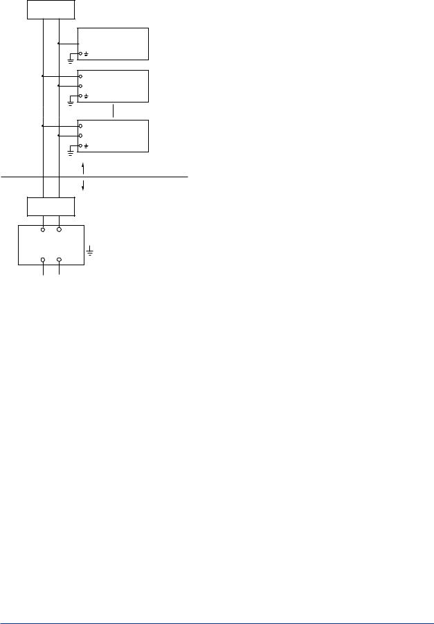
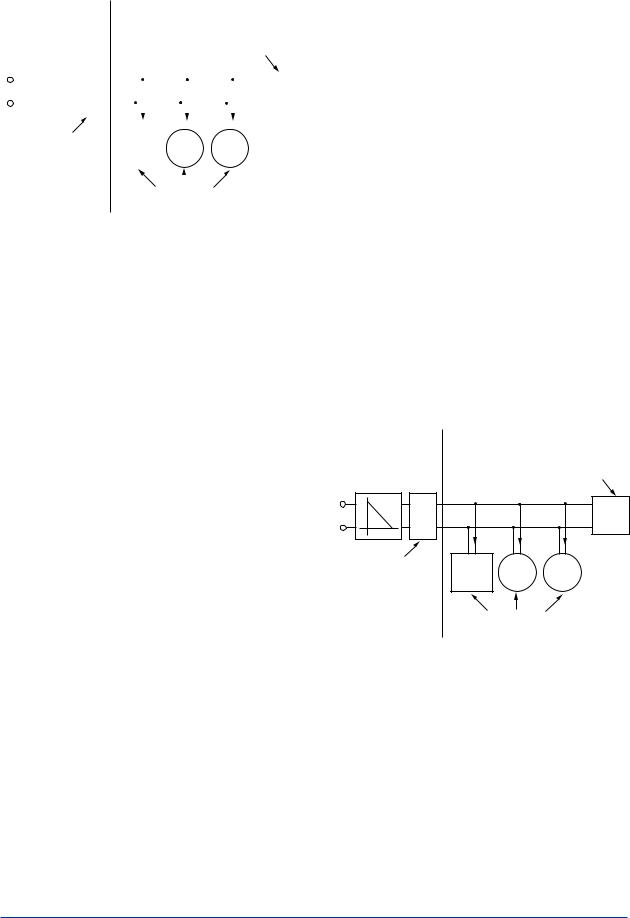
Installation Diagram (Intrinsically safe, Division 1 Installation)
Terminator

 + Valve Positioner
 −
−
+ |
Transmitter |
− |
|
+ |
Transmitter |
− |
|
Hazardous Location
Non-hazardous Location
Terminator
+−
Safety Barrier 
+ −
F0102.ai
Note 4. FISCO rules
The FISCO concept allows the interconnection of intrinsically safe apparatus to associated apparatus not specifically examined in
such combination. The criterion for such interconnection is that the voltage (Ui), the current (Ii) and the power (Pi) which intrinsically safe apparatus can receive and remain intrinsically safe, considering faults, must be equal or greater than the voltage (Uo, Voc, Vt), the current (Io) and the power (Po) which can be provided by the associated apparatus (supply unit). In addition, the maximum unprotected residual capacitance (Ci) and inductance (Li) of each apparatus (other than the terminators) connected to the fieldbus must be less than or equal to 5 nF and 10 µH respectively.
In each I.S. fieldbus segment only one active source, normally the associated apparatus, is allowed to provide the necessary power for the fieldbus system. The allowed voltage Uo of the associated apparatus used to supply the bus is limited to the range of 14 V d.c. to 24 V d.c. All other equipment connected to the bus cable has to be passive, meaning that the apparatus
is not allowed to provide energy to the system, except to a leakage current of 50 µAfor each connected device.
Supply unit
trapezoidal or rectangular output characteristic only
Uo = 14 to 24 V (I.S. maximum value)
Io according to spark test result or other assessment,
e.g. 133 mAfor Uo = 15 V (Group IIC, rectangular characteristic)
No specification of Lo and Co in the certificate and on the label.
Cable
The cable used to interconnect the devices needs to comply with the following parameters:
loop resistance R’: 15 to 150 Ω/km inductance per unit length L’: 0.4 to 1 mH/km capacitance per unit length C’: 80 to 200 nF/km
C’= C’ line/line + 0.5 C’line/screen, if both lines are floating
or
C’= C’line/line + C’line/screen, if the screen is connected to one line
length of spur cable: max. 30 m (Group IIC) or 120 m (Group IIB)
length of trunk cable: max. 1 km (Group IIC) or 1.9 km (Group IIB)
Terminators
At each end of the trunk cable an approved line terminator with the following parameters is suitable:
R = 90 to 100 Ω
C = 0 to 2.2 µF
The resistor must be infallible according to IEC 60079-11. One of the two allowed terminators might already be integrated in the associated apparatus (bus supply unit).
System evaluation
The number of passive devices like transmitters, actuators, hand held terminals connected to a single bus segment is not limited due to I.S. reasons. Furthermore, if the above rules are respected, the inductance and capacitance of the cable need not to be considered and will not impair the intrinsic safety of the installation.
IM 21B04C01-01E
<1. Notes on Handling> |
1-5 |
|
|
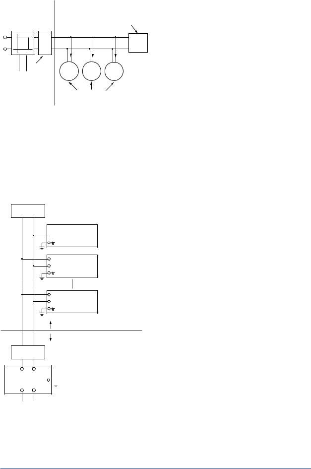
SAFE AREA |
HAZARDOUS AREA |
|
Supply Unit |
Terminator |
|
(FISCO Model) |
(FISCO Model) |
|
U |
Ex i |
|
|
|
|
U |
|
|
I |
|
|
Terminator |
|
|
Data |
|
|
|
Field Instruments |
|
|
(Passive) |
F0103.ai |
|
|
Note 5. Maintenance and Repair
The instrument modification or parts replacement by other than authorized representative of Yokogawa Electric Corporation is prohibited and will void Factory Mutual Intrinsically Safe and Non-incendive Approval.
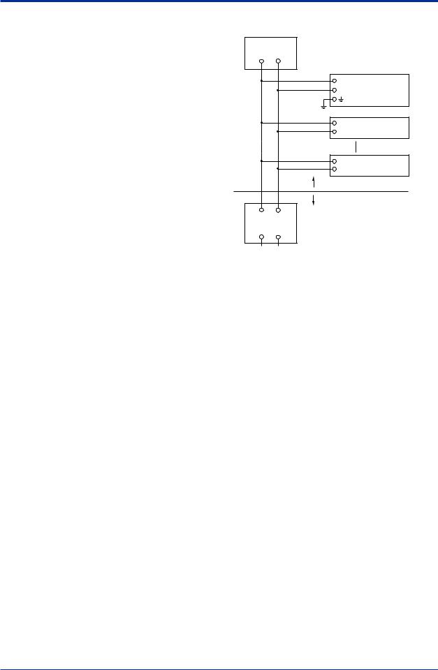
Installation Diagram (Nonincendive, Division 2 Installation)
Terminator

 + Valve Positioner
 −
−
+ |
Transmitter |
− |
|
+ |
Transmitter |
− |
|
Hazardous Location
Non-hazardous Location
Terminator
(Nonincendive) Power Supply 
FM Approved Associated
Nonincendive Field Wiring Apparatus
Vt or Voc
It or Isc
Ca
La
F0104.ai
*1: Dust-tight conduit seal must be used when installed in Class II and Class III environments.
*2: Installation should be in accordance with the National Electrical Code® (ANSI/NFPA70) Sections 504 and 505.
*3: The configuration ofAssociated Nonincendive Field WiringApparatus must be FMApproved.
*4: Associated Nonincendive Field Wiring Apparatus manufacturer’s installation drawing must be followed when installing this equipment.
*5: No revision to drawing without prior FM Approvals.
*6: Terminator and supply unit must be FM Approved.
*7: If use ordinary wirings, the general purpose equipment must have nonincendive field wiring terminal approved by FMApprovals.
*8: The nonincendive field wiring circuit concept allows interconection of nonincendive field wiring apparatus with associated nonincendive field wiring apparatus, using any of the wiring methods permitted for unclassified locations.
*9: Installation requirements; Vmax ≥ Voc or Vt Imax = see note 10. Ca ≥ Ci + Ccable
La ≥ Li + Lcable
*10: For this current controlled circuit, the parameter (Imax) is not required and need not be aligned with parameter (Isc or It) of the barrier or associated nonincendive field wiring apparatus.
Electrical Data:
Maximum Input Voltage Vmax: 32 V
Maximum Internal Capacitance Ci: 1.76 nF
Maximum Internal Inductance Li: 0 µH
B) FM Explosionproof Type
Caution for FM explosionproof type.
Note 1. Model YVP110 Valve Positioner with
optional code /FF1 are applicable for use in
hazardous locations.
•Applicable standard: FM3600, FM3615, FM3810,ANSI/NEMA250
•Explosionproof for Class I, Division 1, GroupsA, B, C and D
•Dust-ignitionproof for Class II/III, Division 1, Groups E, F and G
•Enclosure Rating: NEMA4X
•Temperature Class: T6
•Ambient Temperature: –40 to 80°C
IM 21B04C01-01E
|
<1. Notes on Handling> |
1-6 |
|
Note 2. Wiring |
NFM010-A12 |
|
|
• All wiring shall comply with National Electrical |
Installation Diagram: |
|
|
CodeANSI/NEPA70 and Local Electrical |
|
|
|
|
|
|
|
Codes. |
Terminator |
|
|
• “FACTORY SEALED, CONDUIT SEALNOT |
|
|
|
REQUIRED.” |
+ |
YVP |
|
Note 3. Operation |
|
||
− |
|
||
Valve Positioner |
|
||
• Note a warning label worded as follows; |
|
|
|
WARNING: OPEN CIRCUIT BEFORE |
−+ |
|
|
REMOVING COVER. |
Field Instruments |
|
|
• Take care not to generate mechanical spark |
|
|
|
when accessing to the instrument and |
+ |
|
|
peripheral devices in hazardous locations. |
Field Instruments |
|
|
|
− |
|
|
Note 4. Maintenance and Repair |
Hazardous Area |
|
|
• The instrument modification or parts |
Safe Area |
|
|
replacement by other than authorized |
|
||
|
|
|
|
representative of Yokogawa Electric |
Nonincendive |
|
|
Corporation is prohibited and will void |
Power Supply |
|
|
the approval of Factory Mutual Research |
|
|
|
Corporation. |
|
F0105.ai |
|
|
|
|
|
C) FM Nonincendive approval
Model YVP110Advanced Valve Positioner with optional code /FN15.
•Applicable standard: FM3600, FM3611, FM3810
•NonincendiveApproval
Class I, Division 2, GroupsA, B, C and D Class II, Division 2, Groups F and G Class III, Division 1 and
Class I, Zone 2, Group IIC in Hazardous (Classified) Locations.
Temperature Class: T4
Ambient Temperature: –40 to 60°C Enclosure: NEMAType4X
•Electrical Parameters:
Vmax = 32 Vdc
Ci = 1.76 nF
Li = 0 µ H
•Caution for FM Nonincendive type. (Following contents refer to “DOC. No. NFM010-A12 p.1 and p.2”)
Note 1.
Dust-tight conduit seal must be used when installed in Class II and Class III environments.
Note 2.
Installation should be in accordance with National Electrical Code (ANSI/NFPA70) Sections 504, 505 and Local Electrical Code.
Note 3.
The configuration ofAssociatedApparatus must be Factory Mutual ResearchApproved.
Note 4.
AssociatedApparatus manufacturer's installation drawing must be followed when installing this equipment.
Note 5.
No revision to drawing without prior Factory Mutual ResearchApproval.
Note 6.
Terminator and supply unit must be FM approved.
Note 7.
Installation requirements;
Vmax ≥ Voc or Vt
Ca ≥ Ci + Ccable
La ≥ Li + Lcable
IM 21B04C01-01E

<1. Notes on Handling> |
1-7 |
|
|
1.9.2 ATEX Certification
 WARNING
•Do not open the cover when energized.
•When the ambient temp.≥70°C, Use the heat-resisting cable≥90°C
•Take care not to generate mechanical sparking when access to the instrument and peripheral devices in hazardous locations.
•Electrostatic charge may cause an explosion hazard.
Avoid any actions that cause the generation of electrostatic charge, such as rubbing with a dry cloth on coating face of product.
(1)Technical Data
A) ATEX Intrinsically Safe Type (Ex ia)
Caution forATEX Intrinsically Safe Type.
 NOTE
NOTE
Keep the safety use conditions for both 1G and 1D when used in the hazardous gas and dust area.
Note1. Model YVP110Advanced Valve Positioner with optional code /KS25 for potentially explosive atmospheres:
•Applicable standard: EN60079-0:2006, EN60079-11:2007, EN60079-26:2007, EN60079-27:2006, EN61241-0:2006, EN61241-1:2004, EN61241-11:2006 and EN60529
•Certificate: KEMA08ATEX0114 X
Note 2. Ratings Type of Protection:
II 1G Ex ia IIB/IIC T4
II 1D Ex iaD 20 IP65 T100°C
II 1D Ex tDA20 IP65 T100°C
Maximum Surface Temperature for dust proof.: T100°C
Ambient Temperature Ex ia or Ex iaD: –40°C to +60°C
Ambient Temperature Ex tD: –40°C to +80°C Ambient Humidity: 0 to 100%RH
(No condensation)
Degree of Protection of the Enclosure: IP65 Electrical Parameters:
For Ex ia IIC or Ex iaD
Ui = 24.0 V, Ii = 250 mA, Pi = 1.2 W, Cint = 1.76 nF, Lint = 0 μH
or
For Ex ia IIB/ IIC or Ex iaD (FISCO model) Ui = 17.5 V, Ii = 380 mA, Pi = 5.32 W, Cint = 1.76 nF, Lint = 0 μH
For II 1D Ex tD Input signal: 32 Vdc,
Output current: 17 mA
Note 3. Installation
All wiring shall comply with local installation requirements.
(Refer to the installation diagram)
Note 4. Maintenance and Repair
The instrument modification or parts replacement by other than authorized representative of Yokogawa Electric Corporation is prohibited and will void KEMA Intrinsically safe Certification.
Note 5. Special Conditions for Safe Use Because the enclosure of the Valve Positioner is made of aluminium, if it is mounted in an area where the use of category 1G apparatus is required, it must be installed such, that, even in the event of rare incidents, ignition sources due to impact and friction sparks are excluded.
Once used as apparatus of equipment category 1D in type of protection Ex tD, the valve positioner is no longer suitable as apparatus of equipment category 1G or 1D in type of protection Ex ia or Ex iaD.
Note 6. Installation Instructions
When used in a potentially explosive atmosphere, requiring the use of apparatus of equipment category 1D, suitable certified cable entry devices or certified blanking elements with a degree of ingress protection of at least IP6X according to EN 60529 shall be used and correctly installed.
Note 7. Installation
When used in potentially explosive atmosphere for category 1D, need not use safety barrier.
IM 21B04C01-01E
<1. Notes on Handling> |
1-8 |
|
|
FISCO Model
|
|
Non-hazardous |
Hazardous Locations |
|
||||||||||||||||||
|
|
|
|
|
Locations |
|
|
|
|
|
|
|
|
|
|
|
||||||
|
|
Supply Unit |
|
|
|
|
|
|
Terminator |
|
||||||||||||
|
|
(FISCO Model) |
|
|
|
|
|
|
(FISCO Model) |
|
||||||||||||
|
|
|
|
|
|
|
|
|
|
|
|
|
|
|
Ex i |
|
|
|||||
|
|
U |
|
|
|
|
|
|
|
|
|
|
|
|
|
|
|
|
|
|||
U |
|
|
|
|
|
|
|
|
|
|
|
|
|
|
|
|
|
|
|
|
|
|
|
|
|
|
|
|
|
|
|
|
|
|
|
|
|
|
|
|
|
|
|
|
|
|
|
|
|
|
|
|
I |
|
|
|
|
|
|
|
|
|
|
|
|
|
|
|
|
|
|
|
|
|
|
|
|
|
|
|
|
|
|
|
|
|
|
||||
|
|
|
|
|
|
|
Terminator |
Hand- |
|
|
|
|
|
|
|
|
||||||
|
|
|
|
|
|
|
|
|
|
|
|
held- |
|
|
|
|
|
|
|
|||
|
|
|
|
Data |
|
|||||||||||||||||
|
|
|
|
Terminal |
|
|
|
|
|
|
|
|||||||||||
|
|
|
|
|
|
|
|
|
|
|
|
|
|
|
|
|||||||
|
|
|
|
|
|
|
|
|
|
|
|
|
|
|
|
|
||||||
|
|
|
|
|
|
|
|
|
|
|
|
|
|
Field Instruments |
|
|||||||
|
|
|
|
|
|
|
|
|
|
|
|
|
|
|
(Passive) |
F0106.ai |
||||||
I.S. fieldbus system complying with FISCO
The criterion for such interconnection is that the voltage (Ui), the current (Ii) and the power (Pi), which intrinsically safe apparatus can receive, must be equal or greater than the voltage (Uo), the current (Io) and the power (Po) which can be provided by the associated apparatus (supply unit). In addition, the maximum unprotected residual capacitance (Ci) and inductance (Li) of each apparatus (other than the terminators) connected to the fieldbus line must be equal or less than 5 nF and 10 µH respectively.
Supply unit
The supply unit must be certified by a notified body as FISCO model and following trapezoidal output characteristic is used.
Uo = 14 to 24 V (I.S. maximum value)
Io based on spark test result or other assessment, ex. 133 mAfor Uo = 15 V (Group IIC)
The maximum allowed Co and Lo are determined by the combinations as specified below.
Cable
The cable used to interconnect the devices needs to comply with the following parameters:
loop resistance R': 15 to 150 Ω/km inductance per unit length L': 0.4 to 1 mH/km capacitance per unit length C': 80 to 200 nF/km C' = C' line/line + 0.5 C' line/screen, if both lines are floating
or
C' = C' line/line + C' line/screen, if the screen is connected to one line
length of spur cable: max. 30 m (Ex ia IIC T4) or 120 m (Ex ia IIB T4)
length of trunk cable: max. 1 km (Ex ia IIC T4) or 1.9 km (Ex ia IIB T4)
Terminators
The terminator must be certified by a notified body as FISCO model and at each end of the trunk cable an approved line terminator with the following parameters is suitable:
R = 90 to 100 Ω
C = 0 to 2.2 µF
The resistor must be infallible according to EN 50020. One of the two allowed terminators might already be integrated in the associated apparatus (bus supply unit).
Number of Devices
The number of devices (max. 32) possible on a fieldbus link depends on factors such as the power consumption of each device, the type of cable used, use of repeaters, etc.
Entity Model
Non-hazardous |
Hazardous Locations |
Locations |
|
Supply Unit |
Terminator |
Ex i
U
U
I

 Terminator Handheld- Data Terminal
Field Instruments
(Passive) F0107.ai
I.S. fieldbus system complying with Entity model
IM 21B04C01-01E

<1. Notes on Handling> |
1-9 |
|
|
I.S. values Power supply-field device: Po ≤ Pi, Uo ≤ Ui, Io ≤ Ii
Calculation of max. allowed cable length:
Ccable ≤ Co - ∑ci - ∑ci (Terminator) Lcable ≤ Lo - ∑Li
Number of Devices
The number of devices (max. 32) possible on a fieldbus link depends on factors such as the power consumption of each device, the type of cable used, use of repeaters, etc.
B) ATEX Flameproof Type
Caution forATEX flameproof type.
Note 1. Model YVP110 Valve Positioner with optional code /KF2 is applicable for potentially explosive atmospheres:
•Applicable standard: EN60079-0:2009, EN60079-1:2007
•Certificate: KEMA10ATEX0023 X
•Group: II
•Category: 2G
•Type of Protection and Marking Code: Ex d IIC, T6 or T5 Gb
•Ambient Temperature: T6; –40 to 65°C
T5; –40 to 80°C
Note 2. Electrical Data
•Supply voltage: 32 V DC max.
•Output signal: 17 mADC
Note 3. Installation Instructions
•The cable glands and blanking elements shall be certified in type of protection flameproof enclosure “d” suitable for the conditions of use and correctly installed.
•With the use of conduit entries a sealing device shall be provided either in the flameproof enclosure or immediately on the entrance thereto.
•To maintain the degree of ingress protection IP65 according to EN 60529 special care must be taken to avoid water entering the breathing and draining device when the valve positioner is mounted with the feedback shaft in the upright position.
Note 4. Operation
•Keep strictly the WARNING on the label on the positioner.
AFTER DE-ENERGIZING, DELAY 5 MINUTES BEFORE OPENING. WHEN THEAMBIENTTEMP. ≥ 70°C,
USE HEAT-RESISTING CABLE & CABLE GLAND ≥ 90°C.
Note 5. Maintenance and Repair
•The instrument modification or parts replacement by other than authorized representative of Yokogawa Electric Corporation is prohibited and will void KEMA Flameproof Certification.
C)ATEX Intrinsically safe (Ex ic)/Type n (Ex nA)
Note 1. Model YVP110Advanced Valve Positioner
with optional code /KN25
•Applicable standard: EN60079-0:2009/EN60079-0:2012(Ex ic/Ex nA), EN60079-11:2012(Ex ic) EN60079-15:2010(Ex nA)
•Ex ic: II 3G Ex ic IIC T4 Gc (Intrinsically safe)
•Ex nA: II 3G Ex nAIIC T4 Gc (Non-sparking)
•Ambient Temperature: -30 to 75°C
•Ambient Humidity:
0 to 100%RH (No condensation)
•Enclosure: IP65
•Installation category: I
Note 2. Electrical Data
•Ex ic: Ui = 32 V, Ci = 3.52 nF, Li = 0 μH
•Ex nA: 32 V DC MAX
Note 3. For the installation of this positioner, once a particular declared type of protection is selected, the other type of protection
cannot be used. The installation must be in accordance with the description about type of protection in this instruction manual.
Note 4. In order to avoid confusion, unnecessary marking is crossed out on the label other than the selected type of protection when positioner is installed.
Note 5. Installation Instructions
•Cable glands, adapters and/or blanking elements shall be of Ex “n”, EX “e” or Ex “d” and shall be installed so as to maintain the specified degree of protection (IP Code) of the equipment.
•To maintain the degree of protection IP65 according to IEC 60529, special care must be taken to avoid water.
Note 6. Maintenance and Repair
•The instrument modification or parts replacement by other than authorized representative of Yokogawa Electric Corporation is prohibited and will voidATEX Ex ic and Ex nA.
IM 21B04C01-01E
<1. Notes on Handling> |
1-10 |
|
|
Note 7. Ex ic Installation
•All wiring shall comply with local installation requirements (refer to the installation diagram)
Installation Diagram
Hazardous Area |
Non-hazardous Area |
Valve Positioner |
Associated Apparatus |
+ |
+ |
− |
− |
F0108.ai
Electrical Data: Ui = 32 V
Ci = 3.52 nF
Li = 0 μH
Note 8. Ex ic Specific Conditions of Use
 WARNING
•Electrostatic charge may cause an explosion hazard.Avoid any actions that cause the generation of electrostatic charge, such as rubbing with a dry cloth on coating face of product.
•When the lightning protector option is specified (/A), the apparatus is not capable of withstanding the 500V insulation test required by EN60079-11. This must be taken into account when installing the apparatus.
•WHEN THEAMBIENTTEMP.≥70°C, USE THE HEAT-RESISTING CABLEAND CABLE GRAND≥90°C
•POTENTAIALELECTROSTATIC CHARGING HAZARD – SEE USER’S MANUAL
Note 9. Ex nAInstallation
•Screws of terminals for field wiring connections shall be tightened with specified torque values: 1.2 N·m
 WARNING
When using a power supply not having a nonincendive circuit, please pay attention not to ignite in the surrounding flammable atmosphere. In such a case, we recommend using wiring metal conduit in order to prevent the ignition.
Note 10.Ex nASpecific Conditions of Use
 WARNING
•Electrostatic charge may cause an explosion hazard.Avoid any actions that cause the generation of electrostatic charge, such as rubbing with a dry cloth on coating face of product.
•WHEN THEAMBIENTTEMP.≥70°C, USE THE HEAT-RESISTING CABLEAND CABLE GRAND≥90°C
•POTENTAIALELECTROSTATIC CHARGING HAZARD – SEE USER’S MANUAL
•DO NOT OPEN INAN EXPLOSIVE ATMOSPHERE WHEN ENERGIZED
(2)Electrical Connection
The type of electrical connection is stamped near the electrical connection port according to the following marking.
Screw Size |
Marking |
ISO M20 × 1.5 female |
M |
ANSI 1/2 NPT female |
N |
 Location of the marking
F0109.ai
(3) Installation
 WARNING
All wiring shall comply with local installation requirement and local electrical code.
IM 21B04C01-01E
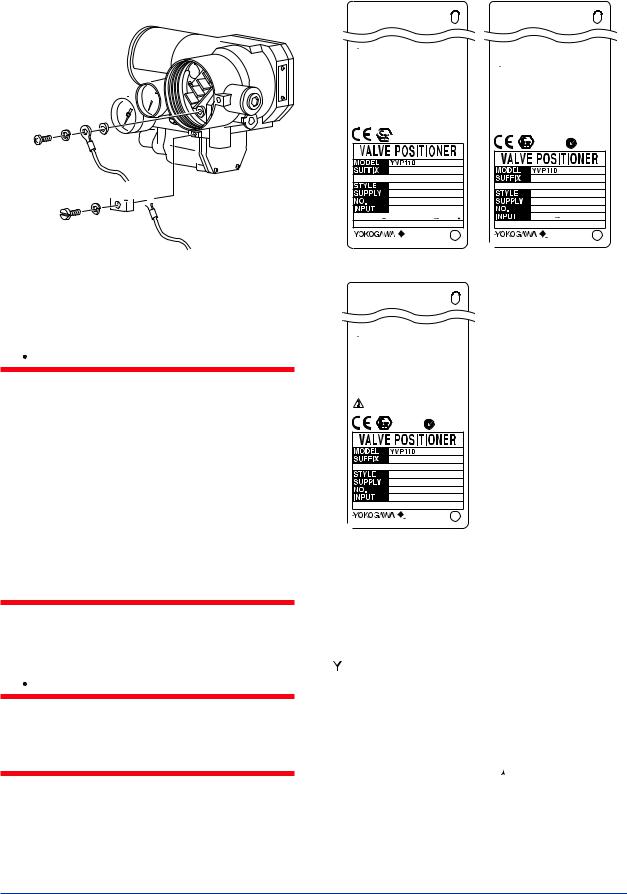
<1. Notes on Handling> |
1-11 |
|
|
The grounding terminals are located on the inside and outside of the terminal area.
Connect the cable to grounding terminal in accordance with wiring procedure 1) or 2).
1) Internal grounding 
 terminal


2) External grounding terminal 


F0111.ai
Wiring Procedure for Grounding Terminals
(4) Operation
 WARNING
•OPEN CIRCUIT BEFORE REMOVING COVER. INSTALLINACCORDANCE WITH THIS USER’S MANUAL
•Take care not to generate mechanical sparking when access to the instrument and peripheral devices in hazardous locations.
•Electrostatic charge may cause an explosion hazard.
Avoid any actions that cause the generation of electrostatic charge, such as rubbing with a dry cloth on coating face of product.
•Carbon disulphide is excluded for enclosures under gas atmosphere.
(5)Maintenance and Repair
 WARNING
The instrument modification or parts replacement by other than authorized Representative of Yokogawa Electric Corporation is prohibited and will void the certification.
(6) Name Plate
●Name plate for intrinsically safe type
F9176LL
YVP KS25
 WARNING
DON'T OPEN WHEN ENERGIZED.
WHEN THE AMBIENT TEMP. ≥70°C
USE THE HEAT-RESISTING CABLE ≥90°C
No. KEMA 08ATEX0114 X II 1G Ex ia IIB/IIC T4
II 1D Ex iaD 20 IP65 T100°C II 1D Ex tD A20 IP65 T100°C ENCLOSURE:IP65
For II 1G Ex ia IIC or II 1D Ex iaD
Ui=24V Ii=250mA Pi=1.2W Ci=1.76nF Li=0µH
For II 1G Ex ia IIC/IIB or II 1D Ex iaD (FISCO field device) Ui=17.5V Ii=380mA Pi=5.32W Ci=1.76nF Li=0µH
For II 1D Ex tD
Input signal:32V Output current:17mA
0344


 II 1G,1D
  N200
N200
FoundationFieldbus
9-17.5(24)VDC (Ex ia, iaD) 9-32.0VDC
 (Ex tD)
*3
TOKYO 180-8750 JAPAN Made in Japan
●Name plate for /KN25 (Ex ic, Ex nA)
F9176MQ
YVP KN25
 WARNING
WHEN THE AMBIENT TEMP.≥70°C,
USE THE HEAT-RESISTING CABLE & CABLE GLAND ≥90°C. POTENTIAL ELECTROSTATIC CHARGING HAZARD.
- SEE USER’S MANUAL
DO NOT OPEN IN AN EXPLOSIVE ATMOSPHERE WHEN ENERGIZED
Ex nA IIC T4 Gc |
Ex ic IIC T4 Gc |
Tamb −30 TO 75°C |
Tamb −30 TO 75°C |
ENCLOSURE : IP 65 |
ENCLOSURE : IP 65 |
SUPPLY 32V DC MAX |
Ui=32V, Ci=3.52nF, Li=0µH |
|
|
CROSS OUT UNNECESSARY MARKING OTHER
THAN THE SELECTED TYPE OF PRPTECTION
II 3G |
N200 |
|
Foundation Fieldbus
*3
 TOKYO 180-8750 JAPAN
Made in Japan
●Name plate for flameproof type
F9176LK
YVP KF2
 WARNING
AFTER DE-ENERGIZING, DELAY 5 MINUTES BEFORE OPENING.
WHEN THE AMBIENT TEMP.≥70°C,
USE THE HEAT-RESISTING CABLE & CABLE GLAND ≥90°C. POTENTIAL ELECTROSTATIC CHARGING HAZARD.
SEE USER’S MANUAL BEFORE USE.
No. KEMA 10ATEX0023X Ex d IIC T6,T5 Gb SUPPLY 32V DC MAX
Tamb −40 TO 65°C(T6),80°C(T5) ENCLOSURE : IP 65
0344
II 2G |
N200 |
|
9-32VDC FoundationFieldbus
*3
 TOKYO 180-8750 JAPAN
Made in Japan
F0110.ai
MODEL: Specified model code.
SUFFIX: Specified suffix code.
STYLE: Style code.
SUPPLY:Air supply pressure.
NO.: Serial number and year of production*1.
INPUT: Type of electrical input (FOUNDATION
FIELDBUS).


 TOKYO 180-8750 JAPAN:
The manufacturer name and the address*2.
*1: |
The third figure from the last of the serial number shows |
||||
|
the year of production. For example, the production year |
||||
|
of the product engraved in “NO.” column on the name |
||||
|
plate as follows is 2001. |
|
|
|
|
|
12A220566 |
108 |
|||
|
|
|
|
|
|
|
|
||||
|
|
|
|||
|
The year 2001 |
||||
|
|
|
|
|
|
*2: |
“180-8750” is a zip code which represents the following |
||||
|
address. |
|
|
|
|
|
2-9-32 Nakacho, Musashino-shi, Tokyo Japan |
||||
*3: |
The production year is shown on the place of *3 (for |
||||
|
example “2013.02).” |
|
|
|
|
IM 21B04C01-01E

<1. Notes on Handling> |
1-12 |
|
|
1.9.3 CSACertification
A) CSAExplosionproof Type
Cautions for CSAExplosionproof type.
Note 1. Model YVP110Advanced Valve Positioner
with optional code /CF1 are applicable for
use in hazardous locations:
•Applicable standard: C22.2 No. 0, No. 0.4, No. 0.5, No. 25, No. 30, No. 94, No. 1010.1
•Certificate: 1186507
•Explosionproof for Class I, Groups B, C and D; Class II, Groups E, F and G; Class III.
•Enclosure Rating: Type 4X
•Temperature Code: T6 and T5
•Ambient Temperature: –40 to 75°C for T6, –40 to 82°C for T5
Note 2. Wiring
•All wiring shall comply with National Electrical CodeANSI/NFPA70 and Local Electrical Codes.
•“FACTORY SEALED, CONDUIT SEALNOT REQUIRED.”
•When the ambient temperature is 60°C or more, use an external cable having a maximum allowable heat-resistance of at least 90°C.
Note 3. Maintenance and Repair
•The instrument modification or parts replacement by other than authorized representative of Yokogawa Electric Corporation is prohibited and will void CSA Certification.
1.9.4 TIIS Certification
A) TIIS Flameproof Type
The model YVP110 Valve Positioner with optional code /JF3, which has obtained certification according to technical criteria for explosionprotected construction of electric machinery and equipment (Standards Notification No. 556 from the Japanese Ministry of Labor) conforming to IEC standards, is designed for hazardous areas where inflammable gases or vapors may be present. (This allows installation in Division 1 and 2 areas)
To preserve the safety of flameproof equipment requires great care during mounting, wiring, and piping. Safety requirements also place restrictions on maintenance and repair activities. Users absolutely must read “Installation and Operating Precautions for JIS Flameproof Equipment” at the end of this manual.
 CAUTION
When selecting cables for TIIS flameproof type positioners, use cables having a maximum allowable heat resistance of at least 70°C.
IM 21B04C01-01E
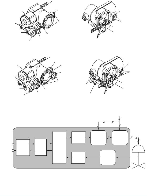
<2. Part Names> |
2-1 |
|
|
2.Part Names
2.1Appearance and Part Names
Single Acting Type |
Feedback lever (Optional) |
|
||
|
|
|||
Name plate |
Terminal cover |
For mounting |
||
|
|
(Normally not used) |
||
Air supply |
Electrical |
|
Air supply connection |
|
connection |
|
|||
connection |
|
|
Feedback shaft |
|
|
|
|
||
Output pressure |
Ground terminal |
|
Control relay |
|
connection |
|
|
||
Air supply pressure gauge |
|
|
||
Output pressure |
For M8 mounting bolt |
|||
gauge (Optional) |
(Optional) |
|
|
|
|
|
|
||
Double Acting Type |
Feedback lever (Optional) |
|
||
|
For mounting |
|||
|
Terminal cover |
|
||
|
|
(Normally not used) |
||
Name plate |
Output pressure |
|||
|
||||
|
connection |
|
||
|
Output pressure |
Air supply |
||
Air supply |
gauge (Optional) |
connection |
||
connection |
|
|
|
|
|
Electrical |
|
Feedback shaft |
|
Output pressure |
connection |
Output pressure |
||
Ground terminal |
gauge (Option) |
Control relay |
||
connection |
|
|||
Output pressure |
Air supply pressure gauge |
Output pressure |
For M8 mounting bolt |
|
gauge (Optional) |
(Optional) |
|||
connection |
F0201.ai |
|||
|
|
|||
2.2Block Diagram
Supply Air Pressure
|
YVP110 |
|
|
|
|
|
|
|
D/A |
I/P Module |
Control |
|
|
|
Conversion |
Relay |
|
|
|
|
|
||
|
Commu- |
|
CPU |
|
|
|
Fieldbus |
|
|
|
|
Fieldbus |
nication |
Digital |
|
|
|
Circuit |
Modem |
|
|
||
|
Processing |
|
|
||
|
Regulator |
|
|
|
|
|
|
Unit |
Position |
|
|
|
|
|
A/D |
|
|
|
|
|
Conversion |
Sensor |
|
F0202.ai
IM 21B04C01-01E
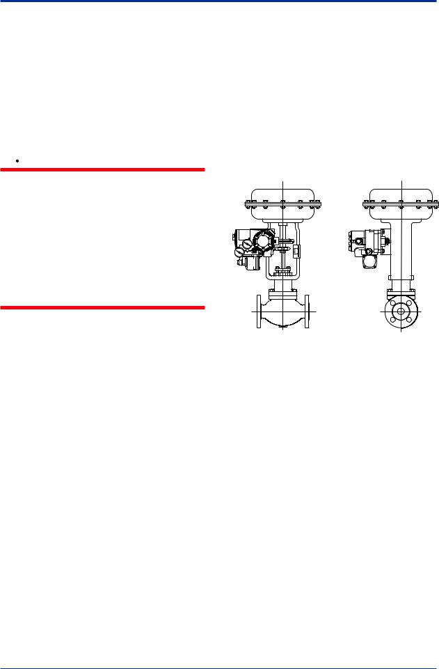
<3. Installing YVP110 onActuator> |
3-1 |
3.Installing YVP110 onActuator
3.1General
For installation of a YVP110, see Section 1.4, “Choosing the Installation Location.” For the ambient, environmental conditions required for installation, see Chapter 7, “General Specifications.”
 WARNING
To avoid injury or the process being affected when installing or replacing a positioner on a control valve, ensure that:
•All inputs to the valve actuator and other accessories of the valve and actuator, including the air supply and electric signal, are cut off.
•The process has been shut down or the control valve is isolated from the process by using bypass valves or the like.
•No pressure remains in the valve actuator.
3.2Installing YVP110 on Actuator
AYVP110 can be installed on a valve actuator with a mounting bracket. Prepare the bracket and clamp which are necessary to install the valve, according to the valve. In general, the installation method is determined by the combination of the control valve and positioner as well as by the valve manufacturer who performs the adjustment. For details, consult the control valve manufacturer.
Required Tools: To install a YVP110, you need to prepare:
•Nominal 13-mm open end or box end wrench for M8 bolts used to fix the mounting bracket to the positioner.
•Nominal 10-mm open end or box end wrench for M6 bolt used to fix the feedback lever to the shaft.
3.2.1Installing YVP110 on Linear-motion Control Valve
The following shows the general installation procedure when assembling a YVP110 with a linear-motion control valve (e.g., a globe valve) combined with a diaphragm actuator or cylinder actuator. Note that the most suitable procedure may differ depending on the shapes of the bracket and valve actuator, and the structure of the mounting position.
F0301.ai
Figure 3.1 YVP Installed on Linear-motion Valve/
Actuator
(1) Fixing Bracket to YVP110
Use the four M8 bolts that come with the YVP110 to tightly fix the mounting bracket to the YVP110. (See “Part Names” on page 2.1) The installation method is determined by the combination of the control valve and positioner as well as by the valve manufacturer who performs the adjustment. For details, consult the control valve manufacturer.
IM 21B04C01-01E
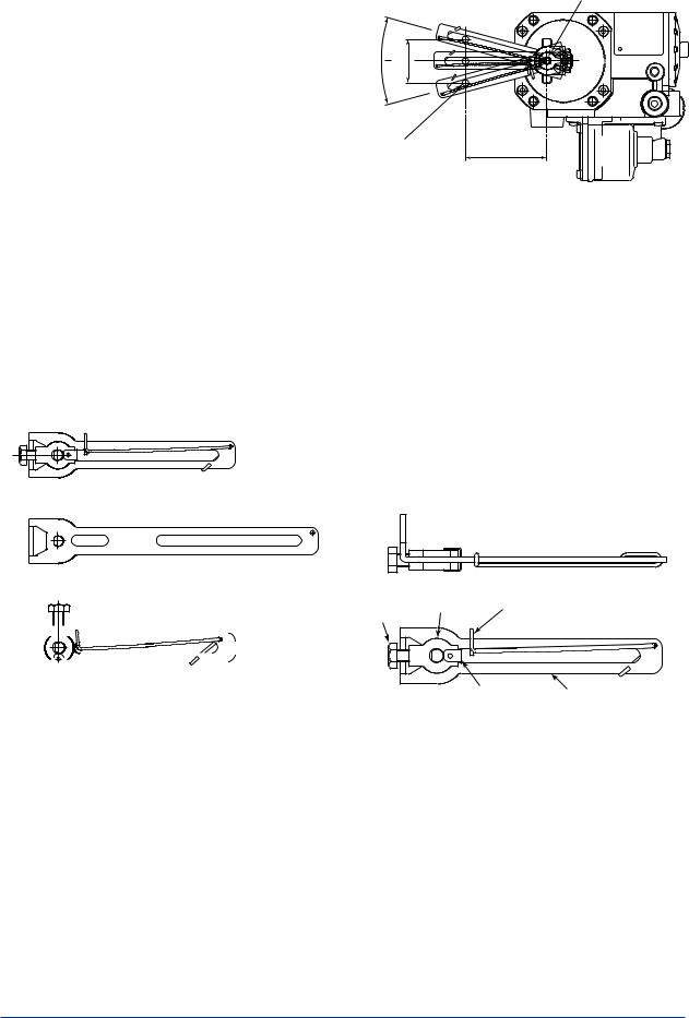
<3. Installing YVP110 onActuator> |
3-2 |
|
|
(2) Fixing the YVP110 toActuator with Bracket
After fixing the bracket to the YVP110, attach it to the actuator with the specified bolts. Depending on the shapes of the bracket and actuator, the working space at the rear of the YVP110 where the feedback shaft is positioned may be quite narrow, making installation work tricky. In such a case, the entire procedure may be made much easier by attaching
the feedback lever to the feedback shaft as described in step (3), prior to carrying out step
(2). Check the space behind the YVP110 beforehand.
(3) Attaching Feedback Lever
The YVP110 with option code /LV1 comes with two different feedback levers, (1) and (2) shown below, and the one with option code /LV2 comes with lever (3). Check the specifications of the levers shown in Table 3.1 and Figure 3.2 and choose the lever most suitable for the control valve used.
(1)F9176HA
(2)F9176HC
Feedback shaft
θ |
X |
|
|
|
SUP |
Clamp pin |
L |
|
on side of valve |
F0303.ai |
|
|
|
|
Figure 3.3 Stroke of Lever
When /LV1 is specified, the hardware for attaching the lever to the feedback shaft and the spring for fixing the clamp pin are attached to the F9176HA, the smaller feedback lever for generally used mid-capacity actuators. Thus, when using the F9176HC, the feedback lever for high-capacity actuators, detach and use the hardware and spring from the F9176HA. See Figure 3.4. To do so, first detach the spring <4>. Then, detach the clip <1> and remove the hardware <2> and <3>. Attach <1> to <4> to the F9176HC feedback lever for highcapacity actuators in the reverse order.
The hardware and the spring attached to the /LV2 lever is not compatible with those for the /LV1 lever.
(3) F9176HD
<3> <2> <4>
|
|
|
|
|
|
|
|
|
|
|
|
|
|
|
|
|
|
|
F0302.ai |
|
|
|
|
|
|
|
|
|
|
|
|
|
|
|
|
|
|
|
|
|
|
|
|
|
|
|
|
|
|
|
|
|
|
|
|
|
|
|
|
Figure 3.2 |
|
|
|
|
Feedback Levers |
|
|
|
|||||||||||
|
|
|
|
|
|
|
|
||||||||||||
Table 3.1 |
|
|
|
|
Specifications of Levers |
||||||||||||||
|
|
|
|
|
|
|
|
|
|
|
|
||||||||
Lever |
|
|
|
Stroke (X) |
Pin-to-shaft |
|
Allowable Range of |
||||||||||||
Model |
|
|
|
Distance (L) |
|
RotationAngle of |
|||||||||||||
|
|
|
|
|
|
|
Feedback Shaft(θ) |
||||||||||||
F9176HA |
|
10 to 60 mm |
25 to 75 mm |
|
|
|
|
||||||||||||
F9176HC |
|
30 to 100 mm |
75 to 115 mm |
|
±10 to 25 degrees |
||||||||||||||
F9176HD |
|
5 to 20 mm |
14 to 20 mm |
|
|
|
|
||||||||||||
Note: When assembling a YVP110 with a linear-motion actuator, ensure that the rotation angle of the YVP110’s feedback shaft does not exceed the allowable range (10 to 25 degrees shown above.
Only if the range of the rotation angle is within this specification, it is guaranteed that the specified accuracy can be obtained by linearity correction (see the description for travel calibration in Section 5.3, “Carrying outAuto Tuning”).
<1> |
Lever |
F0304.ai |
|
|
Figure 3.4 Disassembling a LeverAssembly
When determining which lever to use, follow the procedure below to make a linkage between the YVP110 positioner and control valve’s stem via the clamp and lever. The adjustment of this linkage is a decisive factor for determining the characteristics of the control valve combined with the YVP110 positioner.
(1)Insert the YVP110’s feedback shaft into the small hole on the stopper side of the lever as shown in Figure 3.5.
IM 21B04C01-01E
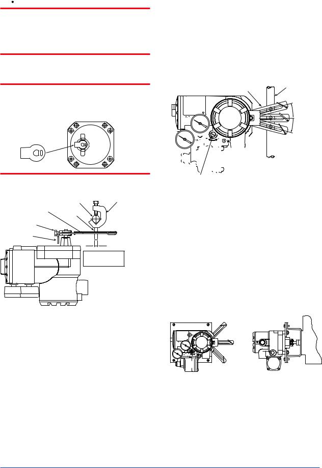
<3. Installing YVP110 onActuator> |
3-3 |
|
|
 CAUTION
It is extremely likely that attaching the lever in the wrong orientation will cause the feedback shaft to rotate at an angle exceeding its mechanical limits of ±55 degrees, resulting in the YVP110 being seriously damaged.
 IMPORTANT
Astopper is attached to the feedback shaft to prevent an over-rotation of the shaft as shown below. When installing the lever, make sure that you install it on the stopper.
Stopper |
|
|
|
|
F0311.ai |
Next, fix the lock screw. |
|
|
|
Valve stem |
Clamp |
Feedback lever |
Clamp pin |
|
Lock screw |
|
|
Stopper |
|
|
|
|
Applicable pin |
|
|
O.D.: 6 mm |
F0305.ai
Figure 3.5 Attaching Lever and Clamp
(2)Attach the clamp to the stem in reference with Figure 3.5. It is necessary to set the clamp of the YVP110 in a position that allows the feedback lever to be at an angle within ±15 degrees from the horizontal level when the valve stem is at the 50% position (see Figure 3.6). Installing the YVP110 at a carefully determined position, where the feedback lever is at the horizontal level when the valve stem is at the 50% position, will make the consequent installation work easier.
Note that only if the YVP110 is installed at a position meeting the specification above, it is guaranteed that the specified accuracy can be obtained by linearity correction (see also Section 13.5, “Travel Calibration”).
When using the SingleActing Type, it is possible to adjust the position of the feedback lever while air is being supplied to the actuator. SeeAppendix 5. “POSITIONADJUSTMENT OF FEEDBACK LEVER”.
Lever |
Valve stem |
|
|
|
∆θ |
|
|
|
|
|
|
|
|
|
|
|
|
|
|
|
|
|
|
|
|
|
|
|
|
|
|
|
|
|
|
|
|
|
|
|
|
|
|
|
|
|
|
|
|
|
|
|
|
|
|
|
|
|
|
|
|
|
|
|
|
|
|
|
|
|
|
|
|
|
|
|
|
|
|
|
|
|
|
|
|
|
|
|
|
|
|
|
|
|
|
|
|
|
|
|
|
|
|
|
|
|
|
|
|
|
|
|
|
|
|
|
|
|
|
|
|
|
|
|
|
|
|
|
|
|
|
|
|
|
|
|
|
|
|
|
|
|
|
|
|
|
|
|
|
|
|
|
|
|
|
|
|
|
|
|
|
|
|
|
|
|
|
|
|
|
|
|
|
|
|
|
|
|
|
|
|
|
|
|
|
|
|
|
|
|
|
|
|
|
|
|
|
|
|
|
|
|
|
|
|
|
|
|
|
|
|
|
|
|
|
|
|
|
|
|
|
|
|
|
|
|
|
|
|
|
The incline of lever from the |
||||||
|
|
|
|
|
|
|
|
|
|
|
|
|
|
|
|
|
|
|
|
|
|
|||||||
A/M selector switch |
horizontal level ∆θ when the stroke |
|||||||||||||||||||||||||||
|
|
|
|
|
|
|
|
|
|
|
|
|
|
|
|
|
|
|
|
|
|
of the stem is 50% must be: |
||||||
|
|
|
|
|
|
|
|
|
|
|
|
|
|
|
|
|
|
|
|
|
|
|
|
|
|
|
∆θ ≤ ±15 degrees |
|
|
|
|
|
|
|
|
|
|
|
|
|
|
|
|
|
|
|
|
|
|
|
|
|
|
|
|
|
|
|
|
|
|
|
|
|
|
|
|
|
|
|
|
|
|
|
|
|
|
|
|
|
|
|
|
|
|
F0306.ai |
Figure 3.6 Checking Position at Which Clamp
Should Be Fixed
3.2.2Installing YVP110 on Rotary-motion Control Valve
The following shows the general installation procedure when assembling a YVP110 with a rotary-motion control valve combined with a
diaphragm actuator or cylinder actuator. Note that the most suitable procedure may differ depending on the shapes of the bracket and valve actuator, and the structure of the actuator.
F0307.ai
Figure 3.7 YVP Installed on Rotary-motion Valve/
Actuator
IM 21B04C01-01E
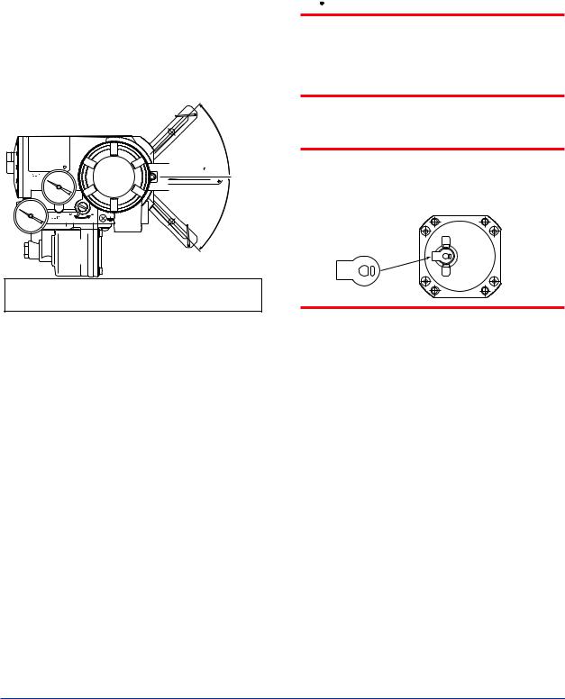
<3. Installing YVP110 onActuator> |
3-4 |
|
|
(1)Allowable Range of RotationAngle of Feedback Shaft
When combining a YVP110 with a rotarymotion actuator, ensure that the rotation of the feedback shaft by the position feedback meets the following specifications:
•Range of rotation angle of shaft: Within ±45 degrees from horizontal level
•Minimum span: 20 degrees
•Maximum span: 90 degrees
•Mechanically allowable rotation angle: ±55 degrees
If any one or more of the specifications above are not met, the specified accuracy may not be guaranteed, resulting in the YVP110 positioner being damaged. An advance check is essential.


 θ
θ
Range of rotation angle of shaft: Within ±45 degrees Mechanically allowable rotation angle: Within ±55 degrees
F0308.ai
Figure 3.8 Allowable Range of RotationAngle of
Feedback Shaft WhenAssembling with
Rotary-motionActuator
(2) Fixing Bracket to YVP110
Use the four M8 bolts that come with the YVP110 to tightly fix the mounting bracket to the YVP110. (See “Part Names” on page 2.1) The installation method is determined by the combination of the control valve and positioner as well as by the valve manufacturer who performs the adjustment. For details, consult the control valve manufacturer.
(3) Attaching Feedback Lever
For a rotary-motion actuator, since it is often difficult to secure sufficient working space between the positioner and actuator, attach the feedback lever before fixing the YVP110 to the actuator. Make sure that the stopper is located on the side of the YVP110 as shown in Figure 3.9.
 CAUTION
It is extremely likely that attaching the lever in the wrong orientation will cause the feedback shaft to rotate at an angle exceeding its mechanical limits of ±55 degrees, resulting in the YVP110 being seriously damaged.
 IMPORTANT
Astopper is attached to the feedback shaft to prevent an over-rotation of the shaft as shown below. When installing the lever, make sure that you install it on the stopper.
Stopper
F0311.ai
Next, fix the lock screw.
(4) Fixing the YVP110 toActuator with Bracket
Insert the pin attached to the valve spindle, into the long hole of the feedback shaft of the YVP110 positioner.
Before fixing the bracket to the actuator, carefully position it so that the center of the rotation axis of the valve plug and that of the YVP110 poistioner’s feedback shaft are aligned both horizontally and vertically. After
the alignment has been checked, tightly fix the bracket to the actuator with the specified bolts. Misalignment of these rotation axes decreases the level of accuracy.
IM 21B04C01-01E
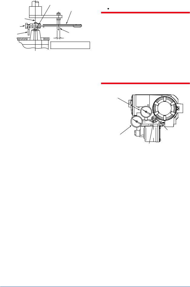
<3. Installing YVP110 onActuator> |
3-5 |
|
|
|
Feedback shaft |
|
Feedback lever |
Rotation axis |
|
of valve plug |
|
Lock screw |
|
Stopper |
Pin |
|
Applicable pin O.D.: 6 mm |
|
F0309.ai |
Figure 3.9 Inserting Pin into Hole of Feedback
Lever (In case of using F9176HA)
3.2.3 A/M Switching
To perform manual operation of the valve using theA/M (automatic/manual) mode switching mechanism of the YVP110, there needs to be a pressure regulator for the air supply. To perform manual operation, follow the procedure below.
(1)Turn theA/M selector switch clockwise to change the switch position to M until it stops.
(2)In manual mode, the pneumatic pressure output to the valve actuator can be varied by changing the regulator output pressure by more than 70 kPa (approximately), regardless of the input signal of the YVP110. For a YVP110 equipped with pressure gauges, you can read the output pressure to the actuator.
When using the DoubleActing Type, the pneumatic pressure can only be varied from OUT1 to the valve actuator. The pressure is always 0% from OUT2 to the valve actuator. Note that the valve position is not always in accord with the regulator pressure.
(3)After you have finished manual operation, turn theA/M selector switch counterclockwise until the stopper pin touches the side of the YVP110’s casing in order to ensure the switch position changes toA.
 WARNING
•Prior to changing theA/M selector switch position, make sure that doing so will neither cause an injury nor affect the process.
•Changing theA/M selector switch position from M (manual) toA(automatic) or A(automatic) to M(manual) during operation will cause the valve stem to temporarily move to a position different from the position determined by the level of the input signal to the positioner.
•If the pressure larger than the allowable range of pressure gauge is applied, the pressure gauge may possibly be damaged.
Supply pressure gauge |
(optional) |
Stopper pin |
Output pressure gauge |
(optional) |
A/M selector switch |
F0310.ai |
Figure 3.10 A/M Selector Switch
IM 21B04C01-01E

<4. Wiring and Piping> |
4-1 |
4.Wiring and Piping
4.1General
This chapter describes the air piping and electric wiring connections.
 WARNING
•Be sure to cut off all inputs to the valve actuator and other accessories of the valve and actuator, including the air supply and electric signal before making or modifying the piping and wiring connections.
•The process must be shut down or the control valve isolated from the process by using bypass valves or the like when making or modifying the piping and wiring connections.
•Always cap the unused wiring ports with blind plugs.
4.2Piping
4.2.1 Air Supply
For stable operation of the YVP110 over a long term, a clean and dry supply of air needs to be maintained. Therefore, be careful about the following:
(1)To prevent moisture, oil, and dust from being led into the YVP110 through pipes, give careful consideration to the choice of the air supply system and supply air suction point as well as installation of the air supply header and air supply piping.
(2)The desired supply air must:
•Be dry air whose dew point is at least 10°C lower than that of the ambient temperature.
•Be free from solid particles as a result of being passed through a 5-µm or finer filter.
•Not contain oil at a concentration higher than 1 ppm in weight or volume.
•Not be contaminated by a corrosive, explosive, flammable, or toxic gas.
•Comply withANSI/ISA-57.3 1975 (R1981) or ISA-S7.3-1975 (R1981).
(3)The YVP110 requires an air supply of 140 to 400 kPa. Within this range, regulate the air supply pressure at a level within ±10% of the air supply pressure specified for the actuator, and at 10% of the actuator’s spring range or higher.
 WARNING
Do not supply air at a pressure exceeding the maximum rated air supply pressure of the actuator or the YVP110 (400 kPa). Doing so may result in a high risk of damage to the equipment or lead to an accident. Supplying air to the valve actuator may cause the valve stem to move. Exercise extreme caution with regard to safety.
4.2.2 Pneumatic Piping
Connect the air supply pipe to the SUP port of the YVP110, and the output pressure pipe to the OUT1 port. When using the DoubleActing Type, connect the output pressure pipe to the OUT2 port of the YVP110.Apower failure will result in the fail-safe action; OUT1=0% and OUT2=100%. Use O.D. 6-mm/I.D. 4-mm or O.D. 8-mm/I.D. 6-mm copper tubes for piping, and pneumatic pipe fittings for joints. After finishing the piping, check that there is no leakage from the joints.
Note that a YVP110 has two air supply ports (SUP): one at the rear and the other on the side. When delivered, the rear SUP port is capped with a blind plug. Thus, to use the rear SUP port, remove the blind plug and cap the side SUP port with it. At this time, be very careful that no foreign matter or dust caught in the sealing tape is allowed to enter inside the pipe.
Figure 4.1 shows the pneumatic piping ports. The port specification can be chosen when ordering the YVP110.
IM 21B04C01-01E
Loading...