


 Loading...
User's
Manual
XL100
Datum-Y
IM XL120P |
|
Quick Setup Manual |
|
|
|
|
|
XL111, XL112, XL114
(Datum-Y) XL121, XL122, XL124
(Datum-Y)
XL111, XL112, XL114
Portable Data Logger (Datum-Y)
XL121, XL122, XL124
Portable Data Station (Datum-Y)
IM XL120P 1st Edition: Apr. 2007(YMI)

Introduction
Thank you for purchasing our XL100 Portable Data Station/Portable Data Logger.
This Quick Setup Manual briefly describes the key operations as well as setting examples of the XL100 upon actual measurement, so that you can operate the XL100 for the first time.
In addition to this manual, the User’s Manual and Communication Function Manual contained in the CD-ROM are available separately. The User’s Manual provides detailed information regarding all of the functions and operations of the XL100 excluding the communication functions. The Communication Function Manual provides information necessary for using communication functions and creating communication programs. Use them together with this Quick Setup Manual. The Communication Function Manual is available only for the Portable Data Station.
After reading this manual, keep it in an easily accessible place for later reference. This manual will come in handy when you are unsure of how to operate the product.
Notes
•The contents of this manual are subject to change without prior notice.
•Figures and illustrations representing display views in this manual may differ from actual views.
•Every effort has been made to ensure accuracy in the preparation of this manual. However, should any doubts arise or errors come to your attention, please contact the vendor from which you purchased the product.
•The contents of this manual may not be transcribed or reproduced, in part or in their entirety, without prior permission.
Trademarks
The company and product names referred to in this document are either trademarks or registered trademarks of their respective holders.
Revisions
First Edition: April, 2007
1st Edition: April 2007 (YMI)
All Rights Reserved, Copyright © 2005, Yokogawa Meters & Instruments Corporation
IM XL120P |
1 |
Safety Precautions
When operating the instrument, be sure to observe the cautionary notes given in “Safety Precautions” on pages 4 and 5 and section 3.1, “Handling Precautions” in the User’s Manual. If you use the instrument in any way other than as instructed, the instrument’s protective measures may be impaired.
The following safety symbols are used on the instrument and in this manual.
 WARNING
Indicates a hazard that may result in the loss of life or serious injury of the user unless the described instruction is abided by.
CAUTION
Indicates a hazard that may result in an injury to the user and/or physical damage to the product or other equipment unless the described instruction is abided by.
Note
Indicates information that is essential for handling the instrument or should be noted in order to familiarize yourself with the instrument’s operating procedures and/or functions.
TIP
Indicates information that complements the present topic.
2 |
IM XL120P |

Contents |
|
|
Introduction ............................................................................. |
1 |
|
Safety Precautions.................................................................. |
2 |
|
1. |
Checking the Contents of the Package ........................ |
4 |
2. |
Flow of Operation ........................................................... |
5 |
3. |
Names and Functions of Parts ...................................... |
6 |
4. |
How to View the Display ................................................. |
9 |
5. |
Introduction of the Main Functions ............................. |
15 |
|
Input Type and Calculation .................................................................. |
15 |
|
Alarm Function ..................................................................................... |
16 |
|
Saving Data ........................................................................................... |
17 |
|
Triggers ................................................................................................. |
18 |
|
File Operations ..................................................................................... |
18 |
|
Communication Function .................................................................... |
19 |
6. |
Operation Mode and Basic Key Operations ............... |
21 |
|
Operation Modes and Switching the Operation Mode ...................... |
21 |
|
Switching the Display in Free Running Mode or Logging Mode ...... |
22 |
|
Switching the menu in Setting Mode .................................................. |
22 |
|
Key Operations for Entering Characters ............................................ |
23 |
|
Key Operations for Entering Values .................................................... |
23 |
7. |
Signal Wiring ................................................................. |
24 |
8.Connecting to the Power Supply and Turning the
|
Power Switch ON/OFF .................................................. |
26 |
|
Connecting the Power Supply ............................................................. |
26 |
|
Turning the Power Switch ON/OFF ..................................................... |
27 |
9. Setting the Input Channel ............................................ |
29 |
|
10. |
Setting the Data Save Operation ................................. |
33 |
11. |
Confirming the Settings and Performing the Measure- |
|
|
ment ............................................................................... |
38 |
12. |
Inserting an External Storage Medium and Saving Data . 39 |
|
|
Inserting an External Storage Medium ............................................... |
39 |
|
Starting the Data Save Operation ....................................................... |
40 |
|
Stopping the Data Save Operation ..................................................... |
40 |
13. |
Analyzing the Saved Data ............................................ |
41 |
|
Loading the Saved Data File ................................................................ |
41 |
|
Loading the Measured Data ................................................................. |
43 |
|
Displaying Statistical Calculation Values ........................................... |
43 |
14. Troubleshooting ............................................................ |
44 |
Index ....................................................................................... |
45 |
IM XL120P |
3 |
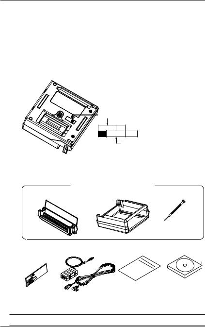
1.Checking the Contents of the Package
Unpack the box and check the contents before operating the instrument. Should the product you have received be the wrong model, lack any items, or show any problems in its appearance, contact the vendor from whom you purchased the product.
Instrument Main Unit
Check the model and suffix code printed on the nameplate on the rear panel to ensure that the XL100 is exactly as specified in your purchase order.
Model
XL100
No.
When inquiring about the product to the vender, please also give the vendor this number.
Accessories
Make sure that the package contains all the accessories listed below and that they are all free from any damage.
These are attached to the XL100.
Terminal block unit |
Rubber boot |
Screwdriver for |
|
terminals |
|||
|
|
+ |
ch1- |
b |
|
+ |
ch2- |
b |
|
+ |
ch3- |
b |
|
+ |
ch4- |
b |
|
+ |
ch5- |
b |
|
+ |
ch6- |
b |
|
+ |
ch7- |
b
(Ex.: 95052)
Side cover (Supplied with the XL121, XL122, and XL124)
+
ch8-

 1.
1.
AC adapter |
Quick setup manual |
CD-ROM |
|
(this manual) |
|
Contains Standard Software and
PDF manuals (User's Manual,
Quick Setup Manual, and
Communication Function Manual).
TIP
For details on peripherals and spare parts, see page 3 in the User’s Manual.
4 |
IM XL120P |
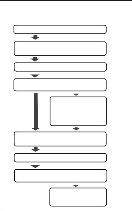
2.Flow of Operation
Connect the wires
Connect the power supply and turn the power ON
|
Reference chapter/ |
Reference page |
section in the |
in this manual |
User’s Manual |
Page 24 |
3.3-3.5 |
Page 26 |
3.6, 4.1 |
Set the language Initial startup only |
Page 28 |
||||||
|
|
|
• Set the input |
Page 29 |
|||
|
|
|
|||||
Configure |
|||||||
• Save the data |
Page 33 |
||||||
|
|
|
|||||
|
|
|
|
|
|
|
|
|
|
|
|
|
|
|
|
Set other items (as necessary)
•Alarm
•Display
•Calculation
•Communications
•Hardware
•System
Confirm the settings
and measure Free Running Mode Page 38
Chapter 5
9.1
Chapter 6
Chapter 7
Chapter 8
Chapter 10 Chapter 4, 11, etc. 11.6, 11.7
Save the data |
Logging Mode |
Page 39 |
9.1 |
|||||
|
|
|
• Review Mode |
Page 41 |
|
|||
|
|
|
|
|||||
Analyze the data |
9.2 |
|||||||
• Logging & Review Mode |
||||||||
|
|
|
|
|
|
|
||
|
|
|
|
|
||||
|
|
|
|
|
|
|
||
|
|
|
Process the file (as necessary) |
|
||||
|
|
|
• Rename the file |
|
9.7 |
|||
|
|
|
• Delete the files |
|
9.8 |
|||
|
|
|
• Copy the data |
|
9.9 |
|||
IM XL120P |
5 |

3.Names and Functions of Parts
Front Panel
Terminal block unit |
Display |
Terminal block unit where |
Displays measured data, operation |
probes are connected. |
status, setup menu, settings, etc. |
For the wiring procedure, |
For the viewing the displays, |
see page 23. |
see page 9. |
|
Status display |
|
section |
|
Data display, |
|
setting menu, |
|
and setting |
|
display section |
HOME REVIEW |
FILE |
SETTING |
HOLD |
|
TIME / DIV |
|
ESC |
SET |
|
|
|
|
|
|
START |
|
|
|
|
/ STOP |
|
|
|
|
RANGE |
DISPLAY |
|
|
|
SAVE |
GROUP |
SELECT |
||
|
|
MARK |
|
|
Operation status LED Keys
POWER : Illuminates when the power is ON
CHARGE : Illuminates when the battery is being charged
START : Illuminates while logging
Keys
1 |
2 |
|
3 |
|
4 |
|
|
HOME REVIEW |
FILE |
|
SETTING |
HOLD |
|
||
9 |
6 |
|
|
|
7 |
5 |
|
|
|
|
|
|
|
|
|
|
TIME / DIV |
|
ESC |
SET |
8 |
||
START |
|
|
|
|
|
|
|
/ STOP |
|
|
|
11 |
|
|
|
10 |
RANGE |
DISPLAY |
|
|
|
||
12 |
SAVE |
|
GROUP |
13 |
SELECT |
|
|
|
|
|
MARK |
|
|
|
|
|
14 |
|
15 |
|
|
16 |
|
6 |
IM XL120P |

3. Names and Functions of Parts
1.HOME Key
Press this key to enable Free Running Mode for measuring instantaneous values (see page 21).
2.REVIEW Key
Press this key to enable Logging & Review Mode in which past measured data can be viewed while logging (see page 21) or enable Review Mode in which saved data can be analyzed (see page 21).
3.FILE Key
Press this key to enable File Operation Mode in which file names can be changed, measured data can be copied, setting data can be saved or loaded, and so on (see page 21).
4.SETTING Key
Press this key to set measurement conditions, conditions for saving measured data, alarm conditions, etc.
5.HOLD Key
Press this key to hold the display so that the measured values are not updated or to release the display. In addition, hold this key down to enable or disable key lock.
6.TIME/DIV Key
Press this key to switch the time axis (the time per grid (division)).
7.ESC Key
Press this key to cancel a key operation.
8.SET Key
Press this key to set settings entered through the keys.
9.START/STOP Key
Press this key to start/stop logging.
10.RANGE Key
Press this key to change the input range or span (scale).
11.DISPLAY Key
Press this key to switch the display in Free Running Mode or Logging Mode (see page 22). Press this key also to switch between marker display and statistical calculation display in Review Mode.
12.SAVE Key
Press this key to manually save or print the measured data or screen data.
13.GROUP Key
Press this key to switch the displayed group of measurement, calculation, and communication input channels.
14.Fast Forward Key
Press this key to move the marker to the left or right by 1 division on the review display (see page 43).
15.MARK Key
Press this key to select a marker to be activated on the review display (see page 43).
16.Arrow/SELECT Key
Press the arrow keys to select items on the display. Press this key also to move the marker to the left or right on the review display (see page 43).
Press the SELECT key to confirm a selection.
IM XL120P |
7 |
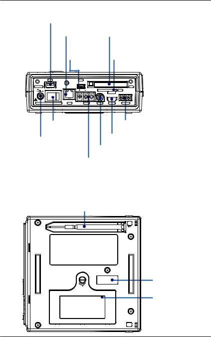
3. Names and Functions of Parts
Side Panel
USB port for USB memory
For a description, see section 3.9. |
The reference sections are those |
|
Ethernet port* |
CF card slot |
of the User’s Manual. |
|
||
|
For a description, |
|
see section 3.8. |
|
USB port for |
|
connecting a PC* |
|
For a description, |
|
see section 3.8. |
USB |
USB |
For a description, see section 4.7.
SD card slot*
For a description, see section 4.7.
For details on how to insert the CF card or SD card, see page 39.
DC INPUT |
|
|
|
|
CF |
12V 20W MAX |
|
SG |
|
SD |
|
|
|
|
|
||
|
|
|
|
IN |
GND OUT |
|
|
|
|
LOGIC/PULSE |
|
POWER |
LAN |
RS485 |
RS232 |
ALARM |
TRIGGER |
Power switch |
Trigger input/output terminal |
|
For a description, |
For a description, see section 3.5. |
|
see section 4.1. |
Digital I/O connector |
|
AC adapter jack |
||
For a description, see section 3.4. |
||
For a description, |
RS-232 connector* |
|
see section 3.6. |
||
For a description, see section 3.8. |
||
For details on connecting |
||
RS-485 connector* |
||
the power supply and |
||
For a description, see section 3.8. |
||
turning the power ON/OFF, |
||
|
||
see pages 26 and 27. |
* Supported only on the XL121, XL122, and XL124 |
Rear Panel
Screwdriver for terminals (accessory)
Press the screwdriver towards the spring (right in this figure) to detach it.
Name plate
Battery cover
Holds the lithium ion battery (94009) sold separately .
8 |
IM XL120P |

4.How to View the Display
Status Display Section
3 |
2 |
1 |
7 |
4 |
5 |
6
8
1.Operation Mode
Displays the mode: Free Running, Logging, Logging & Review, Setup, or File Operation.
2.User name
Displays the login user name when the key login function (see section 11.7 in the User’s Manual) is turned ON.
3.Group Name (For the procedure to set groups, see section 7.2 in the User’s Manual)
Displays the group name of the displayed measurement channel.
4.Alarm Status (For a description of the alarm function, see page 16)
The status is displayed using different icon colors as follows:
Gray: |
No alarm setting |
Yellow-green: |
Alarm setting enabled |
Red: |
Alarm activated |
5.Alarm Output Status
The status is displayed using different icon colors for each alarm output
channel (1 to 4) as follows:
Gray: |
No alarm setting |
Yellow-green: |
Alarm setting enabled |
Red: |
Alarm outputting |
6.Date/Time (For the procedure to set the date/time, see section 4.3 in the User’s Manual)
Displays the year, month, day, hour, minute, and second.
7.Sampling Interval
Displays the sampling interval (measurement/save interval of measured data) when in Free Running, Logging, or Logging & Review Mode.
8.Various Icons
The following icons are used to display the operation status, interface usage status, etc.
An icon shown when the data save destination is set to internal memory. The icon blinks when there is access to the internal memory. The icon is gray when the data save destination is not set to internal memory.
IM XL120P |
9 |
4. How to View the Display
An icon shown when the data save destination is set to internal memory and the save mode is set to DIVISION. The icon blinks when there is access to the internal memory.
An icon shown when the data save destination is set to internal memory and the memory full operation is set to REPEAT. The icon blinks when there is access to the internal memory.
An icon shown when the data save destination is set to internal memory and the memory full operation is set to DELETE. The icon blinks when there is access to the internal memory.
An icon shown when the data save destination is set to internal memory, the save mode is set to DIVISION, and the memory full operation is set to REPEAT. The icon blinks when there is access to the internal memory.
An icon shown when the data save destination is set to internal memory, the save mode is set to DIVISION, and the memory full operation is set to DELETE. The icon blinks when there is access to the internal memory.
An icon shown when the data save destination is set to CF card. The icon blinks when there is access to the CF card. The icon is gray when the data save destination is not set to CF card.
An icon shown when the data save destination is set to CF card and the save mode is set to DIVISION. The icon blinks when there is access to the CF card.
An icon shown when the data save destination is set to CF card and the memory full operation is set to REPEAT. The icon blinks when there is access to the CF card.
An icon shown when the data save destination is set to CF card and the memory full operation is set to DELETE. The icon blinks when there is access to the CF card.
An icon shown when the data save destination is set to CF card, the save mode is set to DIVISION, and the memory full operation is set to REPEAT. The icon blinks when there is access to the CF card.
An icon shown when the data save destination is set to CF card, the save mode is set to DIVISION, and the memory full operation is set to DELETE. The icon blinks when there is access to the CF card.
An icon shown when the data save destination is set to SD card. The icon blinks when there is access to the SD card. The icon is gray when the data save destination is not set to SD card. (Supported only on the XL121, XL122, and XL124.)
An icon shown when the data save destination is set to SD card and the save mode is set to DIVISION. The icon blinks when there is access to the SD card. (Supported only on the XL121, XL122, and XL124.)
An icon shown when the data save destination is set to SD card and the memory full operation is set to REPEAT. The icon blinks when there is access to the SD card. (Supported only on the XL121, XL122, and XL124.)
10 |
IM XL120P |

4. How to View the Display
An icon shown when the data save destination is set to SD card and the memory full operation is set to DELETE. The icon blinks when there is access to the SD card. (Supported only on the XL121, XL122, and XL124.)
An icon shown when the data save destination is set to SD card, the save mode is set to DIVISION, and the memory full operation is set to REPEAT. The icon blinks when there is access to the SD card. (Supported only on the XL121, XL122, and XL124.)
An icon shown when the data save destination is set to SD card, the save mode is set to DIVISION, and the memory full operation is set to DELETE. The icon blinks when there is access to the SD card. (Supported only on the XL121, XL122, and XL124.)
An icon shown when there is data saved in the backup memory. The icon blinks when there is access to the backup memory. The icon is gray when there is no data saved to the backup memory.
An icon shown when the interface is set to LAN, LAN/RS-232, or LAN/RS-485. For other cases, the icon is gray. (Supported only on the XL121, XL122, and XL124.)
An icon shown when the interface is set to USB. For other cases, the icon is gray. (Supported only on the XL121, XL122, and XL124.)
An icon shown when the communication protocol is set to Modbus (slave). The icon is gray when set to Modbus (master). (Supported only on the XL121, XL122, and XL124.)
An icon shown when the communication protocol is set to Modbus (master). The icon is gray when set to Modbus (slave). (Supported only on the XL121, XL122, and XL124.)
An icon shown when the printer output is turned ON and the sampling interval is greater than or equal to 1 minute. The icon is gray when the printer output is OFF. (Supported only on the XL121, XL122, and XL124.)
An icon shown when the printer output is turned ON and the sampling interval is less than or equal to 30 seconds. This indicates that only manual print is valid using the SAVE key. (Supported only on the XL121, XL122, and XL124.)
An icon shown when the display update is held. The icon is gray when the display is not held.
An icon shown when key lock is enabled. The icon is gray when key lock is disabled.
An icon shown when the AC adapter is connected.
An icon shown when the AC adapter is not connected, and the XL100 is
running on a battery. Shows the remaining battery power using four levels ( →
→ →
→ →
→ ).
).
IM XL120P |
11 |
4. How to View the Display
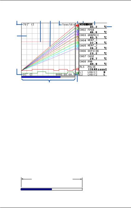
Data Display Section
Waveform & Digital Display
4 |
3 |
1 |
2 |
6 |
12 |
10 |
11
8
5
7 |
9 |
1. Waveform
Waveforms of measured data, calculated data, and communication input data. Waveforms of logic input are shown at the lower section of the screen as shown in the figure above.
2.Time Axis
Displays the time axis (time per grid (division)) specified by the TIME/DIV key.
3.Alarm Line
Displayed with a dotted line at the position of the alarm value of the selected channel (active channel).
4.Scale Upper Limit
Shows the display upper limit of the active channel.
5.Scale Lower Limit
Shows the display lower limit of the active channel.
6.Pen
Displayed at the current value position of each channel. The active channel is shown highlighted in reverse video.
7.Usage Indication Bar of the Storage Media
Displays using a blue bar the amount of space used with respect to the total space on the storage medium that is specified to be the save destination of the measured data.
Total space on the save
destination medium
 Used space
 Free space
8.Grid
The grid can be turned ON/OFF.
12 |
IM XL120P |

4. How to View the Display
9. Elapsed Time
Displays the elapsed time from the start of the logging operation.
10.Digital Display
Displays the current values of the measured data, calculated data, and communication input data using numeric values.When an alarm is occurring, the value is shown in red in reverse video.
11.Unit
Displays preset characters such as °C or an arbitrary specified characters (up to 6 characters).
12.Channel No./Tag
Displays the channel number and the specified tag (up to 8 characters). The active channel is shown highlighted (reverse video).
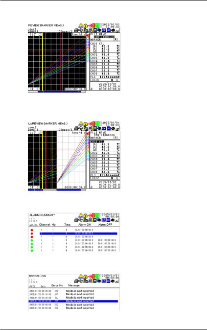
Other Data Displays
In addition to the waveform & digital display, other displays are available including the waveform display that does not show numeric values. For a description of the data displays below, see section 2.3, “Data Display” in the User’s Manual.
•Digital Display
Displays the numeric values of the instantaneous values and statistical calculation values.
•Bar Graph Display
Displays a bar graph in place of a waveform.
IM XL120P |
13 |
4. How to View the Display
•Review Display
Displays the waveforms of data saved in the past.
•Logging & Review Display
Displays both the waveforms of data currently being logged and the waveforms of data saved in the past.
•Alarm Summary Display Displays the alarm status in a list.
•Log Display
Displays the log data of error messages and communications.
14 |
IM XL120P |

5.Introduction of the Main Functions
Input Type and Calculation
As shown in the table below, the available input types are analog input, which includes DC voltage, thermocouple, and RTD, and other inputs, which consist of pulse signal (1 channel) and logic signals (2 channels).
In addition, the arithmetic calculations between two inputs can be performed and assigned to a calculation channel and displayed in the same fashion as measured values. The statistics of measured values can also be displayed.
For details on the input settings, see chapter 5, “Setting the Input Channels.” For details on calculation, see chapter 8, “Setting the Calculation of Measured Data.”
Input/Calculation |
Description |
||||||||
DC voltage |
Measures a DC voltage in the range of ±100 mV to ±50 V. |
||||||||
|
|
|
|
|
|
|
|
|
|
Thermocouple |
Selectable from the following types: R, S, B, K, E, J, T, N, W, |
||||||||
|
L, and U. |
||||||||
|
|
|
|
|
|
|
|
|
|
RTD |
Selectable from Pt100 and JPt100 types. |
||||||||
|
|
|
|
|
|
|
|
|
|
Pulse signal |
Displays the pulse input as number of revolutions, integrated |
||||||||
|
value, or instantaneous value. |
||||||||
|
|
|
|
|
|
|
|
|
|
Logic signal |
Displays the logic waveform at the lower section of the display by |
||||||||
|
taking input voltage less than or equal to 0.9 V to be OFF (0) and |
||||||||
|
input voltage greater than or equal to 2.1 V to be ON (1). |
||||||||
|
|
|
|
|
|
|
|
|
|
Calculation |
Performs arithmetic calculations using measured data, |
||||||||
|
calculated data, communication data, and arbitrary assigned |
||||||||
|
constants and displays the result. |
||||||||
|
|
|
|
|
|
|
|
|
|
Statistical calculation |
Calculates and displays the maximum, minimum, average, |
||||||||
|
peak (P-P), or rms value of the measured value. |
||||||||
|
|
|
|
|
|
|
|
|
|
|
Displays the measured/calculated data |
||||||||
|
|
|
|
|
|
|
|
||
Signal input |
|
|
|
|
|
|
|
|
|
|
|
|
|
|
|
|
|
||
Voltage |
|
|
|
Pulse/Logic |
|||||
|
|
|
|||||||
|
|
|
|
||||||
Thermocouple |
|
|
|
input |
|||||
|
|
|
|
|
|
|
|
|
|
RTD |
|
|
|
|
|
|
|
|
|
|
|
|
|
|
|
|
|
|
|
|
|
|
|
|
|
|
|
|
|
TIP
You must connect a digital I/O cable sold separately to the input terminal (digital I/O connector) to apply pulse or logic signals.
(See section 3.4 in the User's Manual.)
IM XL120P |
15 |
Loading...