


 Loading...
User’s
Manual AQ7270 Series
OTDR
IM 735020-01E
7th Edition
Product Registration
Thank you for purchasing YOKOGAWA products.
YOKOGAWA provides registered users with a variety of information and services.
Please allow us to serve you best by completing the product registration form accessible from our homepage.
http://tmi.yokogawa.com/
PIM 103-03E

Foreword
Thank you for purchasing the AQ7270 Series (AQ7270/AQ7275) OTDR (Optical Time Domain Reflectometer).
This user’s manual contains useful information about the instrument’s functions and operating procedures and the handling precautions of the AQ7270 Series OTDR.
To ensure correct use, please read this manual thoroughly before beginning operation. After reading the manual, keep it in a convenient location for quick reference whenever a question arises during operation.
Three manuals, including this one, are provided as manuals for the AQ7270 Series OTDR. Please read all of them.
Manual Title |
Manual No. |
Description |
AQ7270 Series OTDR User’s Manual |
IM 735020-01E |
This manual. Explains all functions |
|
|
and procedures of the AQ7270/ |
|
|
AQ7275 excluding the remote |
|
|
control functions. |
AQ7270 Series OTDR |
IM 735020-02E |
Explains briefly the functions |
Operation Guide |
|
and basic operations. |
AQ7270 Series OTDR Communication |
IM 735020-17E |
Explains the functions for |
Interface User’s Manual |
|
controlling the AQ7270/AQ7275 |
|
|
using communication commands. |
Notes
•The contents of this manual are subject to change without prior notice as a result of continuing improvements to the instrument’s performance and functions. The figures given in this manual may differ from those that actually appear on your screen.
•Every effort has been made in the preparation of this manual to ensure the accuracy of its contents. However, should you have any questions or find any errors, please contact your nearest YOKOGAWA dealer.
•Copying or reproducing all or any part of the contents of this manual without YOKOGAWA’s permission is strictly prohibited.
Trademarks
•The fiber Xplorer is the registered trademark of Yokogawa Electric Corporation.
•Microsoft, Windows, and Windows XP are either registered trademarks or trademarks of Microsoft Corporation in the United States and/or other countries.
•Adobe and Acrobat are trademarks of Adobe Systems Incorporated.
•For purposes of this manual, the TM and ® symbols do not accompany their respective trademark names or registered trademark names.
•Other company and product names are trademarks or registered trademarks of their respective holders.
Revisions
•1st Edition: December 2006
•2nd Edition: January 2007
•3rd Edition: December 2007
•4th Edition: February 2008
•5th Edition: December 2008
•6th Edition: June 2009
•7th Edition: September 2011
7th Edition : September 2011 (YMI)
All Rights Reserved, Copyright © 2006, Yokogawa Electric Corporation
All Rights Reserved, Copyright © 2011, Yokogawa Meters & Instruments Corporation
IM 735020-01E
i

Checking the Contents of the Package
Unpack the box and check the contents before operating the instrument.
If some of the contents are not correct or missing or if there is physical damage, contact the dealer from which you purchased them.
AQ7270 Series
MODEL
AQ7270
MODEL |
Suffix Code |
Description |
735020 |
|
1550 nm, 32 dB |
735021 |
|
1650 nm, 30 dB |
735022 |
|
1310/1550 nm, 34/32 dB |
735023 |
|
1310/1550 nm, 40/38 dB |
735024 |
|
1550/1625 nm, 38/35 dB |
735025 |
|
1310/1490/1550 nm, 34/30/32 dB |
735026 |
|
1310/1550/1625 nm, 34/32/28 dB |
735027 |
|
1310/1550/1650 nm, 34/32/30 dB |
735028 |
|
1310/1550/1625 nm, 40/38/35 dB |
735029 |
|
850/1300 nm, 22.5/24 dB (GI (62.5/125mm)) |
735030 |
|
850/1300 nm, 22.5/24 dB (GI (62.5/125mm)) |
|
|
1310/1550 nm, 34/32 dB |
|
|
|
AQ7275 |
|
|
MODEL |
Suffix Code |
Description |
735031 |
|
1650 nm, 30 dB |
|
|
(15dB if the suffix code is /PN) |
735032 |
|
1310/1550 nm, 34/32 dB |
|
|
(36/34 dB if the suffix code is /DR) |
735033 |
|
1310/1550 nm, 40/38 dB |
|
|
(23/21dB if the suffix code is /PN) |
735034 |
|
1310/1550 nm, 43/41 dB |
735035 |
|
1310/1490/1550 nm, 34/30/32 dB |
735036 |
|
1310/1550/1625 nm, 40/38/33 dB |
|
|
(23/21/16dB if the suffix code is /PN) |
735037 |
|
1310/1550/1650 nm, 40/38/30 dB |
735038 |
|
1310/1550/1625 nm, 40/38/36 dB |
|
|
(23/21/16dB if the suffix code is /PN) |
735040 |
|
850/1300 nm, 22.5/24 dB (GI (62.5/125mm)) |
|
|
1310/1550 nm, 40/38 dB |
735041 |
|
850/1300 nm, 22.5/24 dB (GI (62.5/125mm)) |
|
|
21.5/23 dB (GI (50/125mm)) |
|
|
1310/1550 nm, 40/38 dB |
|
|
|
ii
IM 735020-01E

|
|
|
|
Checking the Contents of the Package |
|
|
AQ7270/AQ7275 |
|
|
|
|
|
MODEL |
Suffix Code |
Description |
|
|
|
Optical connector |
-SCC |
SC connector (fixed) |
|
|
|
|
|
-FCC |
FC Connector (fixed) |
|
|
|
|
-ASC |
Angled PC SC Connector *1 |
|
|
|
|
-NON |
No universal adapter |
|
|
|
|
-USC |
SC universal adapter |
|
|
|
|
-UFC |
FC universal adapter |
|
|
|
|
|
|
|
|
Language |
-HE |
English |
|
|
|
|
|
-HC |
Chinese/English |
|
|
|
|
-HK |
Korean/English |
|
|
|
|
-HR |
Russian/English |
|
|
|
|
|
|
|
Power cord |
-D |
UL/CSA standard |
Max. rated voltage: 125 V |
||
|
|
|
-F |
VDE standard |
Max. rated votlage: 250 V |
|
|
|
-R |
AS standard |
Max. rated votlage: 250 V |
|
|
|
-Q |
BS standard |
Max. rated votlage: 250 V |
|
|
|
-H |
GB standard |
Max. rated votlage: 250 V |
|
|
|
-P |
EK standard |
Max. rated votlage: 250 V |
Options |
/PM |
Optical power monitor function *2 |
|
/SLS |
Stability Light source function *3 |
|
/LS |
Light source function *4 |
|
/VLS |
Visible Light source function *5 |
|
/PL |
Internal printer and LAN (Ethernet interface) |
|
/DF |
Dummy fiber (SMF) *6 |
|
/SB |
Shoulder belt |
|
/DR |
Dynamic range expansion (2 dB) *7 |
|
/PN |
PON measurement*8 (firmware version 2.07 or later) |
*1 Supported by the SMF port of the 735031 to 735038, 735040 and 735041, or supported by the visible light source output port of the 735031 to 735035 and 735038.
*2 Not supported by 735021, 735029 and 735031, and the MMF of 735030, 735040 and 735041 *3 Not supported by 735020 to 735030, and 735040
*4 Not supported by 735029, 735032, 735033 and 735037, and the MMF of 735030 and 735040
*5 Supported by 735031 to 735035 and 735038
*6 Not supported by 735029, 735030, 735040 and 735041 *7 Supported by 735032
*8 Supported by 735031, 735033, 735036 and 735038
•No. (Instrument No.)
When contacting the dealer from which you purchased the instrument, please give them this number.
IM 735020-01E |
iii |
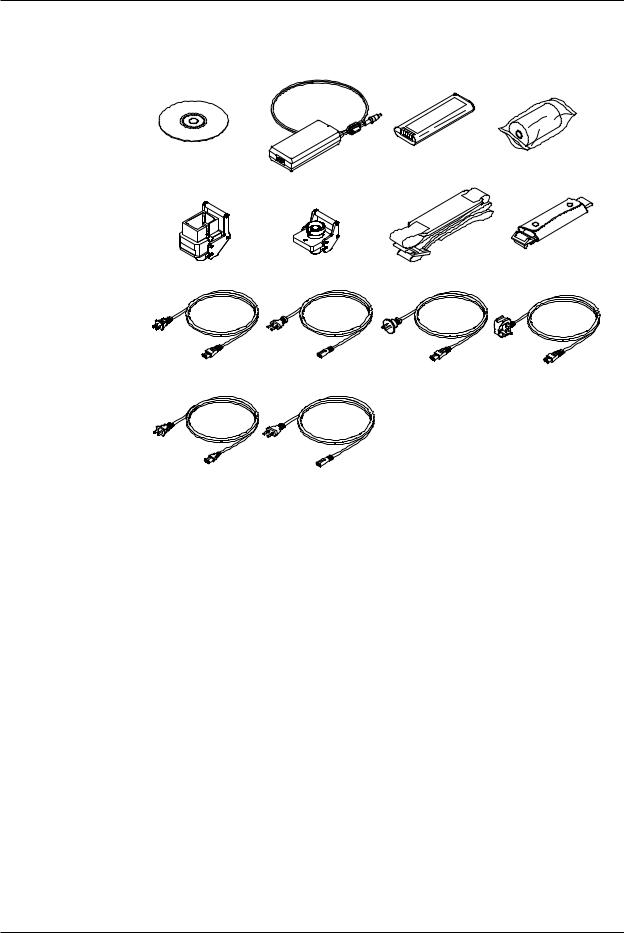
Checking the Contents of the Package
Standard Accessories
The standard accessories below are supplied with the instrument.
AQ7270 Series OTDR |
AC adapter |
Battery pack |
Printer roll paper |
User’s Manual |
739870-D/F/R/Q/H/P |
739880 |
A9010ZP*1 |
B8070TH |
|
|
|
Universal connector |
Universal connector |
Shoulder belt*4 |
Hand belt |
(SC) SU2005A-SCC*2 |
(FC) SU2005A-FCC*3 |
B8070CY |
B8070CX |
Power cord |
Power cord |
Power cord |
Power cord |
UL/CSA St’d A1068WD |
VDE St’d A1071WD |
AS St’d A1070WD |
BS St’d A1069WD |
Power cord
GB St’d A1076WD
Power cord
EK St’d A1078WD
*1 Included if the suffix code is /PL.
*2 Included if the suffix code is -USC.
*3 Included if the suffix code is -UFC. *4 Included if the suffix code is /SB.
Optional Accessories (Sold Separately)
The optional accessories below are available for purchase separately.
Name |
Part Number |
Notes |
Soft carrying case |
738960 |
Soft case |
Emulation software |
735070 |
Waveform analysis application |
Printer roll paper |
A9010ZP |
80 mm width × 25 m roll: 10 rolls per |
|
|
unit |
Battery pack(reserve) |
739880 |
|
External Large Capacity Battery 739881 |
Attached Connecting Cord and Battery |
|
|
|
case |
Universal adapter(SC) |
SU2005A-SCC |
SC type |
Universal adapter(FC) |
SU2005A-FCC |
FC type |
Shoulder belt |
B8070CY |
|
AC adapter(reserve) |
739870-D |
UL/CSA standard |
|
739870-F |
VDE standard |
|
739870-R |
AS standard |
|
739870-Q |
BS standard |
|
739870-H |
GB standard, Complied with CCC |
|
739870-P |
EK standard |
|
|
|
iv
IM 735020-01E

Safety Precautions
To use the instrument safely and effectively, be sure to observe the precautions given in the user’s manual.
The following symbols are used on this instrument.
Warning: handle with care. Refer to the user’s manual or service manual. This symbol appears on dangerous locations on the instrument which require
special instructions for proper handling or use. The same symbol appears in the corresponding place in the manual to identify those instructions.
Hazard, radiation of laser apparatus
Direct current
Stand-by (power)
Recycle
Ni-MH
Double insulation mark (equipment protected throughout by double insulation or reinforced insulation)
IM 735020-01E |
v |

Safety Precautions
Make sure to comply with the precautions below. Not complying might result in injury or death, or damage to the instrument.
WARNING
Use the Correct Power Supply
Before connecting the power cord, ensure that the source voltage matches the rated supply voltage of the AC adapter and that it is within the maximum rated voltage of the provided power cord.
Use the Correct Power Cord
Use only the power cord that comes with the instrument. Do not use it for other devices.
Use the Correct AC Adapter
Use only the AC adapter specified for the instrument. Do not use it for other devices.
Use Only the Designated Battery pack
Use only the battery pack specified for the instrument. Do not use it for other devices.
Use only this instrument or a charger specified by YOKOGAWA to charge the battery pack. If the fast charge does not finish after three hours or more, stop charging the battery pack immediately.
Because the electrolyte solution inside the battery pack is alkaline, harm can be done to the clothes or skin, if the battery pack leaks or explodes and the solution comes in contact. If the electrolyte solution enters the eye, it can cause blindness. In such cases, do not rub the eye. Rinse thoroughly with water and immediately consult your eye doctor.
To prevent the possibility of electric shock and accidents, always turn OFF the power switch and remove the AC adapter power supply from the instrument when replacing the battery pack.
Do not throw the battery pack into fire or apply heat to it. This can cause dangerous explosions or spraying of the electrolytes.
Do Not Look at the Laser Light
Do not look at the laser’s direct ray, reflected ray from a mirror, or indirect ray without the proper protective eyewear. In addition, avoid being exposed to the laser light. It can cause blindness or damage to the eye.
Do Not Operate in an Explosive Atmosphere
Do not use the thermocouple in a location where any flammable or explosive gas/ vapor is present. Operation in such an environment constitutes a safety hazard.
Do Not Remove Covers
The covers should be removed by YOKOGAWA’s qualified personnel only. Opening the cover is dangerous, because some areas inside the instrument have high voltages.
Carrying and Moving the Instrument
Remove all power cords and connection cables from the main unit before moving the instrument. When carrying the instrument, hold it firmly by the handle.
Also, if storage media is inserted into the instrument, always remove the storage media before carrying or moving the instrument. Never leave the media inserted when carrying or moving. The storage media can become damaged.
Apply Correct Signals to the Optical Connectors (PORT1 and PORT2)
Do not apply light that is —5 dBm or greater to the AQ7270/AQ7275 optical connectors (PORT1 and PORT2).
Doing so may damage the AQ7270/AQ7275.
vi
IM 735020-01E

Safety Precautions
CAUTION
When Measuring with the Same Wavelength as the Communication Light
Most instrument models use the same wavelength for measurement as is used for communication. If communication light is present in an optical fiber being measured, this has an affect on the communication itself. Take sufficient precautions to avoid interruption of communications. The measurements by the
instrument may also be incorrect, therefore the measuring environment (presence or absence of communication light, etc.) should be carefully considered.
When Measuring with a Wavelength Different from the Communication Light (1625/1650 nm)
When there is communication light in the fiber under test, use a wavelength different from the communication light for measurement.
If no cutoff filter of 1625 nm or 1650 nm is installed in an instrument connected to the system under test, or depending on the instrument’s lightfastness power rating or characteristics of the cutoff filter such as its attenuation, the pulse light output from the instrument can, in the worst case, damage the instrument. Check that an appropriate cutoff filter is installed and that there is no problem with the instrument’ s ratings, then take sufficient caution during use.
When Using the Angled PC SC Connector (Suffix Code:-ASC)
•Use the same type of angled PC SC connector for the connected optical fiber cable as well.
The ferrule end of the angled PC SC connector is polished to an angle.
If other types of connectors are used, the end face of the connector may become damaged.
•You can replace the AQ7270/AQ7275 connector, but only with an SC type.
See below for operating environment limitations.
CAUTION
This product is a Class A (for industrial environments) product. Operation of this product in a residential area may cause radio interference in which case the user will be required to correct the interference.
IM 735020-01E |
vii |
Safety Precautions
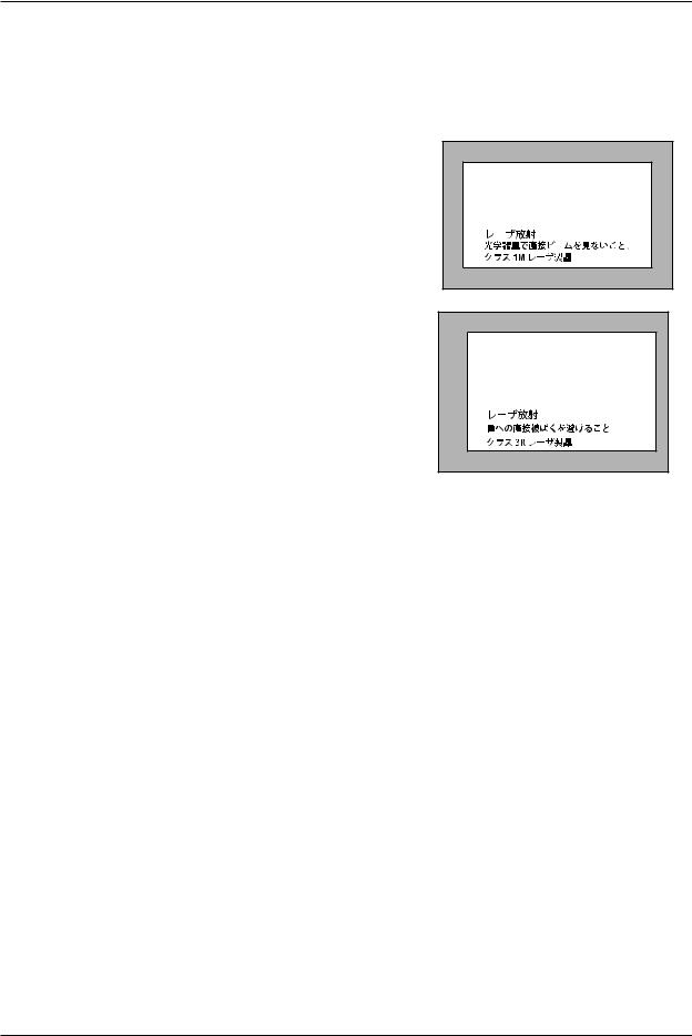
Safety Precautions for Laser Products
This instrument uses a laser light source. This instrument is a Class 1M laser product as defined by IEC60825-1 Safety of Laser Products-Part 1: Equipment Classification, Requirements and User’s Guide. In addition, the AQ7270/AQ7275 complies with
21 CFR 1040.10 except for the items that deviate from the standard as a result of complying with Laser Notice No.50 dated on June 24, 2007.
Laser Class 1M Label
If the laser output is observed at a distance of 100mm or less from the laser beam emitting part by means of optical method (loupe, magnifying glass, microscope, etc.), this may cause eye injury.
INVISIBLE LASER RADIATION DO NOT VIEW DIRECTY WITH OPTICAL INSTRUMENTS CLASS 1M LASER PRODUCT (IEC 60825-1:2007)
Laser Class 3R Label
Avoid direct eye exposure
VISIBLE LASER RADIATION AVOID DIRECT EYE EXPOSURE CLASS 3R LASER PRODUCT (IEC 60825-1:2007)
MAX OUTPUT WAVELENGTH 5mW 650±20nm
MODEL |
Class |
Center Wavelength |
Output Power |
|
735020 |
1M |
1550 nm |
CW: |
≤ 5 mW@1550 nm |
|
|
|
PULSE: |
≤ 200 mW@1550 nm |
|
|
|
PULSE width: ≤ 20 us@1550 nm (duty cycle: ≤ 2.5%) |
|
735021 |
1M |
1650 nm |
CW: |
≤ 5 mW@1650 nm |
|
|
|
PULSE: |
≤ 32 mW@1650 nm |
|
|
|
PULSE width: |
≤ 20 us@1650 nm (duty cycle: ≤ 2.5%) |
735022 |
1M |
1310/1550 nm |
CW: |
≤ 5 mW@1310/1550 nm |
|
|
|
PULSE: |
≤ 200 mW@1310/1550 nm |
|
|
|
PULSE width: |
≤ 20 us@1310/1550 nm (duty cycle: ≤ 2.5%) |
735023 |
1M |
1310/1550 nm |
CW: |
≤ 5 mW@1310/1550 nm |
|
|
|
PULSE: |
≤ 200 mW@1310/1550 nm |
|
|
|
PULSE width: |
≤ 20 us@1310/1550 nm (duty cycle: ≤ 2.5%) |
735024 |
1M |
1550/1625 nm |
CW: |
≤ 5 mW@1550/1625 nm |
|
|
|
PULSE: |
≤ 200 mW@1550/1625 nm |
|
|
|
PULSE width: |
≤ 20 us@1550/1625 nm (duty cycle: ≤ 2.5%) |
735025 |
1M |
1310/1490/1550 nm |
CW: |
≤ 5 mW@1310/1490/1550 nm |
|
|
|
PULSE: |
≤ 200 mW@1310/1490/1550 nm |
|
|
|
PULSE width: |
≤ 20 us@1310/1490/1550 nm (duty cycle: ≤ 2.5%) |
735026 |
1M |
1310/1550/1625 nm |
CW: |
≤ 5 mW@1310/1550/1625 nm |
|
|
|
PULSE: |
≤ 200 mW@1310/1550/1625 nm |
|
|
|
PULSE width: |
≤ 20 us@1310/1550/1625 nm (duty cycle: ≤ 2.5%) |
735027 |
1M |
1310/1550/1650 nm |
CW: |
≤ 5 mW@1310/1550/1650 nm |
|
|
|
PULSE: |
≤ 200 mW@1310/1550 nm |
|
|
|
PULSE: |
≤ 32 mW@1650 nm |
|
|
|
PULSE width: ≤ 20 us@1310/1550/1650 nm (duty cycle: ≤ 2.5%) |
|
735028 |
1M |
1310/1550/1625 nm |
CW: |
≤ 5 mW@1310/1550/1625 nm |
|
|
|
PULSE: |
≤ 200 mW@1310/1550/1625 nm |
|
|
|
PULSE width: ≤ 20 us@1310/1550/1625 nm (duty cycle: ≤ 2.5%) |
|
|
|
|
|
|
viii
IM 735020-01E
Safety Precautions
MODEL |
Class |
Center Wavelength |
Output Power |
|
735029 |
1M |
850/1300 nm |
PULSE: |
≤ 50 mW@850 nm |
|
|
|
|
≤ 100 mW@1300 nm |
|
|
|
PULSE width: ≤ 1 us@850 nm (duty cycle: ≤ 5%) |
|
|
|
|
|
≤ 5 us@1300 nm (duty cycle: ≤ 0.6%) |
735030 |
1M |
850/1300 nm |
PULSE: |
≤ 50 mW@850 nm |
|
|
|
|
≤ 100 mW@1300 nm |
|
|
|
PULSE width: ≤ 1 us@850 nm (duty cycle: ≤ 5%) |
|
|
|
|
|
≤ 5 us@1300 nm (duty cycle: ≤ 0.6%) |
|
|
1310/1550 nm |
CW: |
≤ 5 mW@1310/1550 nm |
|
|
|
PULSE: |
≤ 200 mW@1310/1550 nm |
|
|
|
PULSE width: ≤ 20 us@1310/1550 nm (duty cycle: ≤ 2.5%) |
|
735031 |
1M |
1650 nm |
CW: |
≤ 5 mW@1650 nm |
|
|
|
PULSE: |
≤ 32 mW@1650 nm |
|
|
|
PULSE width: ≤ 20 us@1650 nm (duty cycle: ≤ 2.5%) |
|
|
3R |
650 nm |
CW: |
≤ 5 mW@650 nm |
735032 |
1M |
1310/1550 nm |
CW: |
≤ 5 mW@1310/1550 nm |
|
|
|
PULSE: |
≤ 200 mW@1310/1550 nm |
|
|
|
PULSE width: ≤ 20 us@1310/1550 nm (duty cycle: ≤ 2.5%) |
|
|
3R |
650 nm |
CW: |
≤ 5 mW@650 nm |
735033 |
1M |
1310/1550 nm |
CW: |
≤ 5 mW@1310/1550 nm |
|
|
|
PULSE: |
≤ 200 mW@1310/1550 nm |
|
|
|
PULSE width: ≤ 20 us@1310/1550 nm (duty cycle: ≤ 2.5%) |
|
|
3R |
650 nm |
CW: |
≤ 5 mW@650 nm |
735034 |
1M |
1310/1550 nm |
CW: |
≤ 5 mW@1310/1550 nm |
|
|
|
PULSE: |
≤ 200 mW@1310/1550 nm |
|
|
|
PULSE width: ≤ 20 us@1310/1550 nm (duty cycle: ≤ 2.5%) |
|
|
3R |
650 nm |
CW: |
≤ 5 mW@650 nm |
735035 |
1M |
1310/1490/1550 nm |
CW: |
≤ 5 mW@1310/1490/1550 nm |
|
|
|
PULSE: |
≤ 200 mW@1310/1490/1550 nm |
|
|
|
PULSE width: ≤ 20 us@1310/1490/1550 nm (duty cycle: ≤ 2.5%) |
|
|
3R |
650 nm |
CW: |
≤ 5 mW@650 nm |
735036 |
1M |
1310/1550/1625 nm |
CW: |
≤ 5 mW@1310/1550/1625 nm |
|
|
|
PULSE: |
≤ 200 mW@1310/1550/1625 nm |
|
|
|
PULSE width: ≤ 20 us@1310/1550/1625 nm (duty cycle: ≤ 2.5%) |
|
735037 |
1M |
1310/1550/1650 nm |
CW: |
≤ 5 mW@1310/1550/1650 nm |
|
|
|
PULSE: |
≤ 200 mW@1310/1550 nm |
|
|
|
PULSE: |
≤ 32 mW@1650 nm |
|
|
|
PULSE width: ≤ 20 us@1310/1550/1650 nm (duty cycle: ≤ 2.5%) |
|
735038 |
1M |
1310/1550/1625 nm |
CW: |
≤ 5 mW@1310/1550/1625 nm |
|
|
|
PULSE: |
≤ 200 mW@1310/1550/1625 nm |
|
|
|
PULSE width: ≤ 20 us@1310/1550/1625 nm (duty cycle: ≤ 2.5%) |
|
|
3R |
650 nm |
CW: |
≤ 5 mW@650 nm |
735040 |
1M |
850/1300 nm |
PULSE: |
≤ 50 mW@850 nm,PULSE: ≤ 100 mW@1300 nm |
|
|
|
PULSE width: ≤ 1 us@850 nm (duty cycle: ≤ 5%) |
|
|
|
|
|
≤ 5 us@1300 nm (duty cycle: ≤ 0.6%) |
|
|
1310/1550 nm |
CW: |
≤ 5 mW@1310/1550 nm |
|
|
|
PULSE: |
≤ 200 mW@1310/1550 nm |
|
|
|
PULSE width: ≤ 20 us@1310/1550 nm (duty cycle: ≤ 2.5%) |
|
735041 |
1M |
850/1300 nm |
PULSE: |
≤ 50 mW@850 nm,PULSE: ≤ 100 mW@1300 nm |
|
|
|
PULSE width: ≤ 1 us@850 nm (duty cycle: ≤ 5%) |
|
|
|
|
|
≤ 5 us@1300 nm (duty cycle: ≤ 0.6%) |
|
|
1310/1550 nm |
CW: |
≤ 5 mW@1310/1550 nm |
|
|
|
PULSE: |
≤ 200 mW@1310/1550 nm |
|
|
|
PULSE width: ≤ 20 us@1310/1550 nm (duty cycle: ≤ 2.5%) |
|
|
|
|
|
|
If the instrument is used in a manner not specified in this manual, the protection provided by the instrument may be impaired. Yokogawa Electric Corporation assumes no liability for the customer’s failure to comply with these requirements.
IM 735020-01E |
ix |

Waste Electrical and Electronic Equipment
Waste Electrical and Electronic Equipment (WEEE), Directive 2002/96/EC
(This directive is only valid in the EU.)
 This product complies with the WEEE Directive (2002/96/EC) marking requirement. This marking indicates that you must not discard this electrical/ electronic product in domestic household waste.
Product Category
With reference to the equipment types in the WEEE directive Annex 1, this product is classified as a “Monitoring and Control instrumentation” product.
Do not dispose in domestic household waste. When disposing products in the EU, contact your local Yokogawa Europe B. V. office.
x
IM 735020-01E

Symbols and Notation Used in This Manual
Safety Markings
The following markings are used in this manual.
|
Improper handling or use can lead to injury to the user or damage |
|
to the instrument. This symbol appears on the instrument to indicate |
|
that the user must refer to the users manual for special instructions. |
|
The same symbol appears in the corresponding place in the user’ |
|
s manual to identify those instructions. In the manual, the symbol is |
|
used in conjunction with the word “WARNING” or “CAUTION.” |
|
|
WARNING |
Calls attention to actions or conditions that could cause serious or |
|
fatal injury to the user, and precautions that can be taken to prevent |
|
|
|
such occurrences. |
|
|
CAUTION |
Calls attention to actions or conditions that could cause light injury |
|
to the user or damage to the instrument or the user’s data, and |
|
|
|
precautions that can be taken to prevent such occurrences. |
Note
Calls attention to information that is important for proper operation of the instrument.
Notations Used on Pages Describing Operating Procedures
On pages that describe the operating procedures in chapters 4 through 19, the following displayed characters, and terminology are used to distinguish the procedures from their explanations.
Procedure Carry out the procedure according to the step numbers. All procedures are written with inexperienced users in mind; experienced
users may not need to carry out all the steps.
Explanation This section describes the setup items and the limitations regarding the procedures. It may not give a detailed explanation of the function.
For a detailed explanation of the function, see chapter 2.
Displayed Characters and Terminology Used in the Procedural
Explanations
Panel Keys and Soft keys
Bold characters used in the procedural explanations indicate characters that are marked on the panel keys or the characters of the soft keys or menus displayed on the screen.
Unit
k Denotes 1000. Example: 12 kg, 100 kHz
IM 735020-01E |
xi |

Contents
Checking the Contents of the Package............................................................................................. |
ii |
Safety Precautions............................................................................................................................ |
v |
Waste Electrical and Electronic Equipment ...................................................................................... |
x |
Symbols and Notation Used in This Manual .................................................................................... |
xi |
Chapter 1 Names and Functions of Parts
|
1.1 |
Front Panel....................................................................................................................... |
1-1 |
|
1.2 |
Rear Panel ....................................................................................................................... |
1-2 |
|
1.3 |
Side Panel ........................................................................................................................ |
1-3 |
|
1.4 |
Display.............................................................................................................................. |
1-5 |
Chapter 2 |
Measurement Overview |
|
|
|
2.1 |
Measurement Configuration............................................................................................. |
2-1 |
|
2.2 |
Measurement Procedure.................................................................................................. |
2-4 |
|
2.3 |
Viewing the Optical Pulse Measurement Waveform ........................................................ |
2-9 |
|
2.4 |
Distance Measurement ................................................................................................... |
2-11 |
Chapter 3 |
Measurement Preparation |
|
|
|
3.1 |
Connecting the Power Supply .......................................................................................... |
3-1 |
|
3.2 |
Connecting the Optical Fiber Cable ................................................................................. |
3-5 |
|
3.3 |
Setting the Date and Time................................................................................................ |
3-7 |
|
3.4 |
Loading the Printer Roll Paper (Option) ........................................................................... |
3-9 |
|
3.5 |
Connecting the USB Interface........................................................................................ |
3-10 |
|
3.6 |
Connecting the Ethernet Interface (Option)..................................................................... |
3-11 |
|
3.7 |
Attaching the Belt ........................................................................................................... |
3-12 |
Chapter 4 Setting the Optical Pulse Measurement Conditions (Simple Full Auto |
|||
|
Mode) |
|
|
|
4.1 |
Selecting the Test Wavelength ......................................................................................... |
4-1 |
|
4.2 |
Selecting the Approximation Method................................................................................ |
4-3 |
|
4.3 |
Setting Other Items .......................................................................................................... |
4-4 |
Chapter 5 Setting the Optical Pulse Measurement Conditions (Measurement |
|||
|
Wizard Mode) |
|
|
|
5.1 |
Setting the Measurement Conditions ............................................................................... |
5-1 |
|
5.2 |
Setting the Analysis Conditions ........................................................................................ |
5-8 |
|
5.3 |
Setting the Detection Conditions of Reflection and Loss Waveforms ............................. |
5-11 |
|
5.4 |
Setting the File ............................................................................................................... |
5-16 |
Chapter 6 Setting the Optical Pulse Measurement Conditions (Detail Mode |
|||
|
(Manually Setting All Items)) |
|
|
|
6.1 |
Setting the Measurement Conditions ............................................................................... |
6-1 |
|
6.2 |
Setting the Analysis Conditions ...................................................................................... |
6-16 |
|
6.3 |
Setting the Multi Wavelength Measurement Conditions................................................. |
6-22 |
|
6.4 |
Setting the Multi Wavelength Analysis Conditions.......................................................... |
6-25 |
xii
IM 735020-01E

Contents
Chapter 7 Executing the Optical Pulse Measurement (Acquiring Waveforms)
|
7.1 |
Realtime Measurement .................................................................................................... |
7-1 |
|
|
7.2 |
Averaging Measurement .................................................................................................. |
7-5 |
|
|
7.3 |
Displaying the Measurement Conditions.......................................................................... |
7-7 |
|
|
7.4 |
High Resolution Measurement of the Selected Location ................................................. |
7-8 |
|
|
7.5 |
Measuring Multicore Fiber............................................................................................... |
7-11 |
|
|
7.6 |
Warm-up Measurement.................................................................................................. |
7-28 |
|
Chapter 8 |
Zooming the Waveform |
|
|
|
|
8.1 |
Zooming the Display......................................................................................................... |
8-1 |
|
|
8.2 |
Moving the Waveform....................................................................................................... |
8-2 |
|
|
8.3 |
Initializing the Waveform Display...................................................................................... |
8-3 |
|
|
8.4 |
Auto Zoom the Waveform Display.................................................................................... |
8-4 |
|
Chapter 9 |
Macro Measurement |
|
|
|
|
9.1 |
Creating the Measurement Conditions (Defining the Macro Conditions)......................... |
9-1 |
|
|
9.2 |
Saving the Macro Measurement Results ......................................................................... |
9-3 |
|
|
9.3 |
Loading the Measurement Conditions.............................................................................. |
9-9 |
|
|
9.4 |
Executing the Macro....................................................................................................... |
.9-11 |
|
|
9.5 |
Saving/Loading Macro Conditions.................................................................................. |
9-13 |
|
Chapter 10 |
Measuring the Distance |
|
|
|
|
10.1 |
Marker and Cursor Operation......................................................................................... |
10-1 |
|
|
10.2 |
Measuring the Distance.................................................................................................. |
10-9 |
|
|
10.3 |
Moving the Measurement Reference ........................................................................... |
10-12 |
|
Chapter 11 |
Measuring the Splice and Return Loss |
|
|
|
|
11.1 |
Measuring the Splice Loss .............................................................................................. |
11-1 |
|
|
11.2 |
Measurement Taking the Adjacent Splice Loss into Consideration................................. |
11-7 |
|
|
11.3 |
Measuring the Return Loss and Reflection Level............................................................ |
11-9 |
|
Chapter 12 |
Editing the Event List |
|
|
|
|
12.1 |
Viewing the Measured Results....................................................................................... |
12-1 |
|
|
12.2 |
Editing the Waveform ..................................................................................................... |
12-3 |
|
|
12.3 |
Editing the List.............................................................................................................. |
12-14 |
|
Chapter 13 |
Detail Analysis of the Measured Waveform |
|
|
|
|
13.1 |
Displaying the Multiple Waveforms ................................................................................ |
13-1 |
|
|
13.2 |
2-Way Trace ................................................................................................................... |
13-4 |
|
|
13.3 |
Difference Waveform...................................................................................................... |
13-9 |
|
|
13.4 |
Section Analysis ........................................................................................................... |
13-12 |
|
|
13.5 |
Fixing the Waveform..................................................................................................... |
13-14 |
|
Chapter 14 |
Optical Power Monitoring (Option) |
|
|
|
|
14.1 |
Calibration before the Measurement .............................................................................. |
14-1 |
|
|
14.2 |
Setting the Reference..................................................................................................... |
14-2 |
|
|
14.3 |
Selecting the Display Unit .............................................................................................. |
14-3 |
|
|
14.4 |
Selecting the Wavelength............................................................................................... |
14-4 |
|
|
14.5 |
Setting the Offset............................................................................................................ |
14-5 |
|
|
14.6 |
Set the Threshold Level.................................................................................................. |
14-6 |
|
|
|
|
|
|
IM 735020-01E |
|
|
xiii |
|
1
2
3
4
5
6
7
8
9
10
11
12
13
14
15
16
17
18
19
20
21 App Index

Contents
Chapter 15 |
Light Source Operation (Option) |
|
|
|
15.1 |
Light and Stabilized Light Source................................................................................... |
15-1 |
|
15.2 |
Visible Light Source........................................................................................................ |
15-3 |
Chapter 16 |
Checking Fiber End Faces |
|
|
|
16.1 |
Using Fiber Inspection Probes to View the Status of Optional Fiber End Faces. .......... |
16-1 |
Chapter 17 Multi Core Trace Comparison
17.1 |
Measuring Optical Pulses before Work and after Work |
.................................................. 17-1 |
17.2 |
Configuring the Core Information................................................................................. |
17-10 |
17.3 |
Setting Measurement Conditions ................................................................................. |
17-15 |
17.4 |
Setting Analysis Conditions .......................................................................................... |
17-16 |
Chapter 18 Saving, Loading, and Printing Files
18.1 |
Loading and Saving Files ............................................................................................... |
18-1 |
18.2 |
Deleting or Copying the Files ......................................................................................... |
18-8 |
18.3 |
Renaming the File ........................................................................................................ |
18-12 |
18.4 |
Creating, Deleting, and Copying Folders ..................................................................... |
18-14 |
18.5 |
Printing ......................................................................................................................... |
18-18 |
18.6 |
Entering Characters ..................................................................................................... |
18-21 |
18.7 |
Creating Labels ............................................................................................................ |
18-23 |
18.8 |
Initializing (formatting) the internal memory ................................................................. |
18-29 |
Chapter 19 Other Settings
19.1 |
Setting the System ......................................................................................................... |
19-1 |
19.2 |
Setting the Display ......................................................................................................... |
19-9 |
19.3 |
Setting the Network (/PL Option).................................................................................. |
19-18 |
19.4 |
Network File Transfers ................................................................................................. |
19-22 |
19.5 |
Cable Installation Completion Notification.................................................................... |
19-23 |
Chapter 20 Troubleshooting, Maintenance, and Inspection
20.1 |
Troubleshooting.............................................................................................................. |
20-1 |
20.2 |
Error Messages .............................................................................................................. |
20-2 |
20.3 |
Self Test.......................................................................................................................... |
20-7 |
20.4 |
Updating the Firmware ................................................................................................... |
20-8 |
20.5 |
Mechanical Inspection.................................................................................................. |
20-10 |
20.6 |
Checking the Operation................................................................................................. |
20-11 |
20.7 |
Replacing the Battery Pack .......................................................................................... |
20-12 |
20.8 |
Replacing the Optical Adapter...................................................................................... |
20-15 |
20.9 |
Routine Maintenance ................................................................................................... |
20-17 |
20.10 |
Storage Precautions..................................................................................................... |
20-18 |
20.11 |
Recommended Replacement Parts ............................................................................. |
20-19 |
20.12 |
Calibration .................................................................................................................... |
20-20 |
Chapter 21 Specifications
21.1 |
Models............................................................................................................................ |
21-1 |
21.2 |
Optical Section ............................................................................................................... |
21-2 |
21.3 |
General Specifications ................................................................................................... |
21-8 |
21.4 |
External Dimensions .................................................................................................... |
21-10 |
xiv
IM 735020-01E

|
|
Contents |
Appendix |
|
|
Appendix 1 |
Terminology........................................................................................................ |
App-1 |
Appendix 2 |
Key Assignments for the USB104 Keyboard...................................................... |
App-6 |
Appendix 3 |
Example of file input/output................................................................................ |
App-7 |
Index
IM 735020-01E |
xv |
1
2
3
4
5
6
7
8
9
10
11
12
13
14
15
16
17
18
19
20
21 App Index
Chapter 1 Names and Functions of Parts |
|
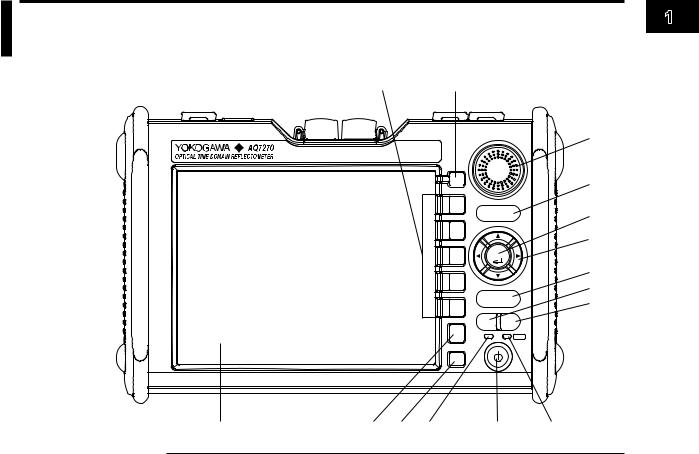
1.1 Front Panel |
1 |
|
15 |
|
|
14 |
|
|
|
Names |
|
|
|
|
|
|
and |
||
|
|
|
|
|
|
|
|
|
|
|
|
|
|
|
|
13 |
ofFunctions |
|
|
|
|
|
|
|
|
|
|
OPTICAL INPUT |
|
|
|
|
|
|
|
|
|
|
|
MENU |
|
|
12 |
Parts |
|
|
|
|
|
|
|
||
|
|
|
|
F 1 |
SCALE |
11 |
||
|
|
|
|
|
||||
|
|
|
|
|
|
|||
|
|
|
|
F 2 |
|
|
10 |
|
|
|
|
|
|
|
|
|
|
|
|
|
|
F 3 |
ENTER |
|
|
|
|
|
|
|
|
|
|
|
|
|
|
|
|
F 4 |
|
|
9 |
|
|
|
|
|
|
|
8 |
|
|
|
|
|
|
|
SETUP |
|
|
|
|
|
|
|
F 5 |
|
7 |
|
|
|
|
|
|
REAL |
|
|
||
|
|
|
|
|
AVG |
|
|
|
|
|
|
|
|
TIME |
|
|
|
|
|
|
|
ESC |
|
|
|
|
|
|
|
|
CHARGE |
|
ON |
|
|
|
|
|
|
FILE |
|
|
|
|
1 |
2 |
3 |
4 |
|
5 |
|
6 |
|
NumberName |
Function |
|
|
|
|
|
|
|
1 |
LCD |
Displays the measured waveforms, measurement |
|
|
conditions, etc. |
2 |
ESC key |
Cancels an operation or returns to the previous display. |
3 |
FILE key |
Operate files and print waveforms. |
|
|
Some also used as soft keys. |
4 |
CHARGE lamp |
Lights (green) while the battery pack is fast charging. |
Turns OFF when the battery pack is finished fast charging.
|
|
Blinks (green) if the battery pack cannot be fast charged. |
5 |
POWER switch |
Turns the instrument on/off |
6 |
POWER lamp |
Illuminates while the instrument is turned on (green). |
When the battery level is low (red).
7 |
AVERAGE key |
Starts or stop the averaging measurement. |
8 |
REALTIME key |
Starts or stop the realtime measurement. |
9 |
SETUP key |
Sets measurement conditions and system configuration. |
|
|
Also used to change the event detection conditions for |
|
|
event analysis. |
10 |
Arrow keys |
Moves, expands, and reduces waveforms, moves cursors, |
|
|
etc. |
11 |
ENTER key |
Confirms the operation |
12 |
SCALE key |
Expands, reduces, and moves waveforms. |
13 |
Rotary knob |
Moves cursors and markers, sets values, etc. |
14 |
MENU key |
Returns to the initial screen at startup. |
|
|
(Selects OTDR, optical power monitor, light source, and |
|
|
one-button measurement.) |
15 |
Soft keys |
Executes functions that are assigned to the soft keys |
|
|
displayed at the right edge of the LCD. |
IM 735020-01E |
1-1 |
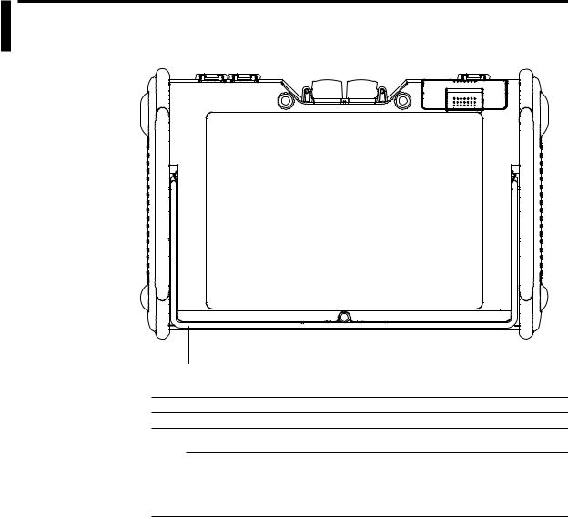
1.2Rear Panel
|
1 |
|
NumberName |
Function |
|
1 |
Stand |
Tilts the instrument. |
Note
•The /PL option does not come with a stand.
•Do not use the stand as a handle to carry the AQ7270/AQ7275.
•Use the stand only to tilt the AQ7270/AQ7275.
•If you are tilting the AQ7270/AQ7275, check that the stand is fixed in place.
1-2 |
IM 735020-01E |

1.3Side Panel
Top View
/PL Option
8 |
|
|
|
|
|
|
|
|
|
|
|
|
|
7 |
|
|
|
6 |
|
|
5 |
|
|
|
|
|
|
|
|
|
|
|
|
|
|
|
|
|
|
|
|
|
|
|
|
|
|
|
|
|
||||||||||||||||||||||||||||||||||||
|
|
|
|
|
|
|
|
|
|
|
|
|
|
|
|
|
|
|
|
|
|
|
|
|
|
|
|
|
|
|
|
|
|
|
|
|
|
|
|
|
|
|
|
|
|
|
|
|
|
|
|
|
|
|
|
|
|
|
|
|
|
|
|
|
|
|
|
|
|
|
|
|
|
|
|
|
|
|
|
|
|
|
|
|
|
|
|
|
|
|
|
|
|
|
|
|
|
|
|
|
|
|
|
|
|
|
|
|
|
|
|
|
|
|
|
|
|
|
|
|
|
|
|
|
|
|
|
|
|
|
|
|
|
|
|
|
|
|
|
|
|
|
|
|
|
|
|
|
|
|
|
|
|
|
|
|
|
|
|
|
|
|
|
|
|
|
|
|
|
|
|
|
|
|
|
|
|
|
|
|
|
|
|
|
|
|
|
|
|
|
|
|
|
|
|
|
|
|
|
|
|
|
|
|
|
|
|
|
|
|
|
|
|
|
|
|
|
|
|
|
|
|
|
|
|
|
|
|
|
|
|
|
|
|
|
|
|
|
|
|
|
|
|
|
|
|
|
|
|
|
|
|
|
|
|
|
|
|
|
|
|
|
|
|
|
|
|
|
|
|
|
|
|
|
|
|
|
|
|
|
|
|
|
|
|
|
|
|
|
|
|
|
|
|
|
|
|
|
|
|
|
|
|
|
|
|
|
|
|
|
|
|
|
|
|
|
|
|
|
|
|
|
|
|
|
|
|
|
|
|
|
|
|
|
|
|
|
|
|
|
|
|
|
|
|
|
|
|
|
|
|
|
|
|
|
|
|
|
|
|
|
|
|
|
|
|
|
|
|
|
|
|
|
|
|
|
|
|
|
|
|
|
|
|
|
|
|
|
|
|
|
|
|
|
|
|
|
|
|
|
|
|
|
|
|
|
|
|
|
|
|
|
|
|
|
|
|
|
|
|
|
|
|
|
|
|
|
|
|
|
|
|
|
|
|
|
|
|
|
|
|
|
|
|
|
|
|
|
|
|
|
|
|
|
|
|
|
|
|
|
|
|
|
|
|
|
|
|
|
|
|
|
|
|
|
|
|
|
|
|
|
|
|
|
|
|
|
|
|
|
|
|
|
|
|
|
|
|
|
|
|
|
|
|
|
|
|
|
|
|
|
|
|
|
|
|
|
|
|
|
|
|
|
|
|
|
|
|
|
|
|
|
|
|
|
|
|
|
|
|
|
|
|
|
|
|
|
|
|
|
|
|
|
|
|
|
|
|
|
|
|
|
|
|
|
|
|
|
|
|
|
|
|
|
|
|
|
|
|
|
|
|
|
|
|
|
|
|
|
|
|
|
|
|
|
|
|
|
|
|
|
|
|
|
|
|
|
|
|
|
|
|
|
|
|
|
|
|
|
|
|
|
|
|
|
|
|
|
|
|
|
|
|
|
|
|
|
|
|
|
|
|
|
|
|
|
|
|
|
|
|
|
|
|
|
|
|
|
|
|
|
|
|
|
|
|
|
|
|
|
|
|
|
|
|
|
|
|
|
|
|
|
|
|
|
|
|
|
|
|
|
|
|
|
|
|
|
|
|
|
|
|
|
|
|
|
|
|
|
|
|
|
|
|
|
|
|
|
|
|
|
|
|
|
|
|
|
|
|
|
|
|
|
|
|
|
|
|
|
|
|
|
|
|
|
|
|
|
|
|
|
|
|
|
|
|
|
|
|
|
|
|
|
|
|
|
|
|
|
|
|
|
|
|
|
|
|
|
|
|
|
|
|
|
|
|
|
|
|
|
|
|
|
|
|
|
|
|
|
|
|
|
|
|
|
|
|
|
|
|
|
|
|
|
|
|
|
|
|
|
|
|
|
|
|
|
|
|
|
|
|
|
|
|
|
|
|
|
|
|
|
|
|
|
|
|
|
|
|
|
|
|
|
|
|
|
|
|
|
|
|
|
|
|
|
|
|
|
|
|
|
|
|
|
|
|
|
|
|
|
|
|
|
|
|
|
|
|
|
|
|
|
|
|
|
|
|
|
|
|
|
|
|
|
|
|
|
|
|
|
|
|
|
|
|
|
|
|
|
|
|
|
|
|
|
|
|
|
|
|
|
|
|
|
|
|
|
|
|
|
|
|
|
|
|
|
|
|
|
|
|
|
|
|
|
|
|
|
|
|
|
|
|
|
|
|
|
|
|
|
|
|
|
|
|
|
|
|
|
|
|
|
|
|
|
|
|
|
|
|
|
|
|
|
|
|
|
|
|
|
|
|
|
|
|
|
|
|
|
|
|
|
|
|
|
|
|
|
|
|
|
|
|
|
|
|
|
|
|
|
|
|
|
|
|
|
|
|
|
|
|
|
|
|
|
|
|
|
|
|
|
|
|
|
|
|
|
|
|
|
|
|
|
|
|
|
|
|
|
|
|
|
|
|
|
|
|
|
|
|
|
|
|
|
|
|
|
|
|
|
|
|
|
|
|
|
|
|
|
|
|
|
|
|
|
|
|
|
|
|
|
|
|
|
|
|
|
|
|
|
|
|
|
|
|
|
|
|
|
|
|
|
|
|
|
|
|
|
|
|
|
|
|
|
|
|
|
|
|
|
|
|
|
|
|
|
|
|
|
|
|
|
|
|
|
|
|
|
|
|
|
|
|
|
|
|
|
|
|
|
|
|
|
|
|
|
|
|
|
|
|
|
|
|
|
|
|
|
|
|
|
|
|
|
|
|
|
|
|
|
|
|
|
|
|
|
|
|
|
|
|
|
|
|
|
|
|
|
|
|
|
|
|
|
|
|
|
|
|
|
|
|
|
|
|
|
|
|
|
|
|
|
|
|
|
|
|
|
|
|
|
|
|
|
|
|
|
|
|
|
|
|
|
|
|
|
|
|
|
|
|
|
|
|
|
|
|
|
|
|
|
|
|
|
|
|
|
|
|
|
|
|
|
|
1
Parts of Functions and Names
|
1 |
2 |
3 |
4 |
|
|
|
|
|
NumberName |
|
Function |
|
|
1 |
DC power connector |
|
Connects the AC adapter. |
|
2 |
Optical connector |
|
Connects the optical fiber cable. *1 |
|
3 |
USB 1.1 connector (Type A) |
|
Connects a USB memory, USB printer, |
|
|
|
|
the USB104 keyboard etc. |
|
4 |
USB 1.1 connector (Type B) |
|
Used for remote control, storage, etc. |
|
5 |
Internal printer |
|
Prints waveforms and event lists.(/PL option) |
|
6 |
Printer paper feed button |
|
Feeds the paper.(/PL option) |
|
7 |
Ethernet connector |
|
Used for remote control.(/PL option) |
|
8 |
Battery pack storage |
|
Stores the battery pack. |
|
*1 The /PM option supports only PORT1. PORT2 (MMF) and 1650-nm wavelength are not supported.
IM 735020-01E |
1-3 |
1.3 Side Panel
Right View
3
/PL option |
2 |
|
1 |
4
NumberName |
Function |
|
1 |
Printer cover |
Stores the paper. |
2 |
Lock lever |
Fixes the printer cover in place. |
3 |
Shoulder belt bracket |
Attaches the shoulder belt. |
4 |
Hand belt bracket |
Attaches the hand belt. |
|
|
|
1-4 |
IM 735020-01E |
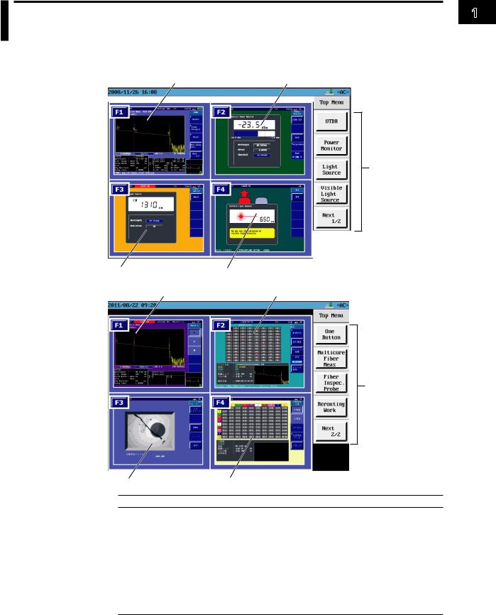
1.4Display
Top Menu
1 |
2 |
5
3 |
4 |
6 |
7 |
5
1
Parts of Functions and Names
8 |
9 |
NumberFunction
1Optical pulse measurement (OTDR) screen.
2Optical power monitor screen (/PM option).
3Light source screen (/LS /SLS option).
4Visible Light source screen (/VLS option).
5Displays the soft key menu.
6One-button measurement screen.
7multicore fiber measurement (main view display) screen.
8Displays the fiber inspection probe screen.
9Displays the Multi Core Trace Comparison (main view) screen (firmware versions 3.01 and later).
IM 735020-01E |
1-5 |

1.4 Display
Note
Displays a shaded area when the option is not installed (firmware version 3.01 or later).
A shaded area
1-6 |
IM 735020-01E |

1.4 Display
Optical Pulse Measurement (OTDR)
21 |
20 |
22 |
19 |
18 |
16 |
15 |
17 |
14 |
|
|
|
|
|
|
|
|
1
2
3 |
|
|
|
|
13 |
4 |
|
|
5 |
|
|
6 |
|
|
|
7 |
12 |
|
11 |
|
|
|
|
|
|
10 |
8 |
|
9 |
|
|
NumberFunction
1Displays the value per scale mark on the vertical axis.
2Shows the display start level of the vertical axis (top edge of the waveform display area)
3Waveform display area
4Displays the value per scale mark on the horizontal axis.
5Shows the display start distance of the horizontal axis (left edge of the waveform display area)
6Displays the distance from the measurement reference point of the horizontal axis to the cursor position.
7Displays the measurement conditions.
8Displays an explanation of the function
9Displays the computed result of the measured data.
10Displays the full screen of the waveform display area. The section displayed in the waveform display area is indicated with a frame (overview).When adjusting the scale using Zoom or Shift, the color of the frame is different. When you press Shift, the word “SHIFT” is displayed at the upper right of the overview screen.
11Displays the sampling resolution.
12Shows the display end distance of the horizontal axis (right edge of the waveform display area)
13Displays the soft key menu.
14Displays the type of power in use (battery pack or AC adapter)
15Displays the cursor movement setting.
16Displays the approximation method.
17Displays in red the connector in which the optical pulse is output.
18Displays the progress of the averaging measurement (AVE).Displays a bar graph indicating the progress in the text background.
19Label area. The name of the next file to be saved blinks if auto save is turned ON.
20Displays the operating status of the instrument.
While the optical pulse output is ON: “LASER ON” is indicated and the text ckground blinks.
While the optical pulse output is OFF: Operation mode (Simple (Full Auto), measurement Wizard, Detail, or Multi WL)
21Displays the year, month, day, and time.
22FILE name area
1
Parts of Functions and Names
IM 735020-01E |
1-7 |

1.4 Display
Optical Power Monitor(/PM option)
1 |
2 |
3 |
4
NumberFunction
1Displays numerically the optical input power value.
2Displays a graph of the optical input power value.
3Measurement condition display area
4Soft key menu
Light Source(/LS, /SLS option)
1 |
2 |
3
NumberFunction
1Displays the wavelength value.
2Measurement condition display area
3Soft key menu
1-8 |
IM 735020-01E |

1.4 Display
Visible Light source (/VLS option)
1
2
NumberFunction
1Displays the wavelength value.
2Soft key menu
One-Button Measurement
1
2
NumberFunction
1Displays the contents of the macro that is being defined (used to enter the macro while viewing the contents).
2Soft key menu
1
Parts of Functions and Names
IM 735020-01E |
1-9 |

1.4 Display
Fiber Inspection Probe
1
2
NumberFunction
1Displays the fiber inspection probe screen.
2Soft key menu
Multi Core Trace Comparison (Firmware Versions 3.01 and Later)
1
2
3
4
NumberFunction
1Displays the number of the core of the optical fiber cable under measurement.
2Displays the soft key menu.
3Displays the information of the cell that the cursor is at.
4Displays the waveform before work and the waveform after work at the same time.
1-10 |
IM 735020-01E |

Chapter 2 Measurement Overview
2.1Measurement Configuration
Overview of the AQ7270/AQ7275
The AQ7270/AQ7275 is an optical time domain reflectometer that measures optical fiber lengths and losses and identifies failure locations. It is mainly used in the optical fiber installation and maintenance servicing of access networks (communications links
between telephone exchanges and telephone poles) and user networks (communications links between user sites and telephone poles). The light source and optical power monitor functions can also be used as options.
AQ7270/AQ7275 OTDR

 Measurement in Telephone cable installations pole
Closure
Optical fiber cable
Telephone exchanges
Corporate user
Consumer
Analysis Using the Emulation Software
The waveform data that is measured by the AQ7270/AQ7275 can be analyzed on your PC using the AQ7932 OTDR emulation software (version 3.0 or later). The software comes with a report creation wizard that is convenient in creating construction reports.
Precautions for Measurement
When Measuring with the Same Wavelength as the Communication Light
Most instrument models use the same wavelength for measurement as is used for communication. If communication light is present in an optical fiber being measured, this has an affect on the communication itself. Take sufficient precautions to avoid interruption of communications. The measurements by the instrument may also be incorrect, therefore the measuring environment (presence or absence of communication light, etc.) should be carefully considered. For details on fiber-in-use alarm function, see section 6.1.
When Measuring with a Wavelength Different from Communication Light (1625/1650 nm)
When there is communication light in the fiber under test, use a wavelength different from the communication light for measurement.
The instrument is designed to allow measurement that impacts communication as little as possible in such cases, but be sure to install a cutoff filter of 1625 nm or 1650 nm in system under test. If measurements are taken without a cutoff filter installed, communications can be affected and measurements may not be correct. Always check the configuration of the system under test before use (presence or absence of an appropriate cutoff filter, attenuation characteristics, etc.).
IM 735020-01E |
2-1 |
2
Overview Measurement

2.1 Measurement Configuration
Configuration of Peripheral Devices
AC adapter |
Ethernet connector (remote control) |
|
|
|
PC |
|
Optical connector PORT2 |
|
|
(wavelength *1: 650 nm, 850 nm, 1300 nm, and 1650 nm) |
DUT |
|
Optical connector PORT1 |
|
|
(wavelength *2: 1310 nm, 1490 nm, 1550 nm, and 1625 nm) |
DUT |
|
|
|
|
USB connector |
|
|
USB memory USB printer |
USB104 keyboard |
|
|
PC |
|
USB connector |
|
|
(remote control and storage) |
|
*1 The 735021 and 735031 output 1650 nm from PORT1. The 735029 outputs 850 nm and 1300 nm from PORT1. The /PM option supports only PORT1. PORT2 (MMF) and 1650-nm wavelength are not supported.
*2 The 735036 outputs 1650 nm from PORT2.
2-2 |
IM 735020-01E |
2.1 Measurement Configuration
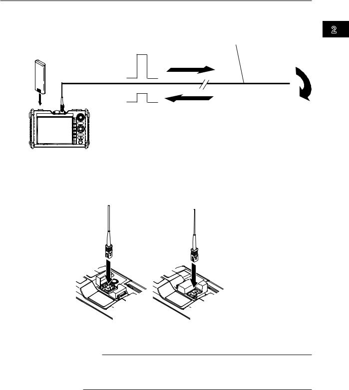
Optical Pulse Measurement (OTDR) Configuration
Install the battery pack and connect the optical fiber cable under measurement.
Optical fiber cable Optical pulse under measurement output
Battery pack
Reflection point
Return ray due to reflection
* Do not bend the optical fiber cable.
There are two optical connectors on the top panel of the AQ7270/AQ7275.Because the connector that delivers the optical pulse is fixed depending on the wavelength, connect the cable to the appropriate connector according to the condition of the optical fiber cable to be measured. You can view the indicator shown on the display (see page 1-5) to choose the appropriate connector.
2
Overview Measurement
[PORT2] |
[PORT1] |
This also applies when using the optional optical power monitor or light source function.
Note
•The 735021 outputs 1650 nm from PORT1.
•The 735029 outputs 850 nm and 1300 nm from PORT1.
•The /PM option supports only PORT1. PORT2 (MMF) and 1650-nm wavelength are not supported.
When Using the Angled PC SC Connector (Suffix Code:-ASC)
•Use the same type of angled PC SC connector for the connected optical fiber cable as well.
The ferrule end of the angled PC SC connector is polished to an angle.
If other types of connectors are used, the end face of the connector may become damaged.
•You can replace the AQ7270/AQ7275 connector, but only with an SC type.
IM 735020-01E |
2-3 |
Loading...