


 Loading...
User’s
Manual
Differential Pressure and
Pressure Transmitters
EJ110, EJ120,
EJ130, EJ310,
EJ430, and EJ440
IM 01C25B01-01E
IM 01C25B01-01E
13th Edition

i
Differential Pressure and Pressure Transmitters
EJ110, EJ120, EJ130,
EJ310, EJ430, and EJ440
|
|
|
IM 01C25B01-01E 13th Edition |
|
Contents |
|
|
|
|
1. |
Introduction............................................................................................... |
|
1-1 |
|
|
Regarding This Manual................................................................................................ |
1-1 |
||
|
1.1 |
Safe Use of This Product ................................................................................. |
1-2 |
|
|
1.2 |
Warranty............................................................................................................. |
|
1-3 |
|
1.3 |
ATEX Documentation........................................................................................ |
1-4 |
|
2. |
Handling Cautions.................................................................................... |
2-1 |
||
|
2.1 |
Model and Specifications Check..................................................................... |
2-1 |
|
|
2.2 |
Unpacking.......................................................................................................... |
2-1 |
|
|
2.3 |
Storage................................................................................................................ |
|
2-1 |
|
2.4 |
Selecting the Installation Location ................................................................. |
2-2 |
|
|
2.5 |
Pressure Connection........................................................................................ |
2-2 |
|
|
2.6 |
Waterproofing of Cable Conduit Connections............................................... |
2-2 |
|
|
2.7 |
Restrictions on Use of Radio Transceivers.................................................... |
2-2 |
|
|
2.8 |
Insulation Resistance and Dielectric Strength Test...................................... |
2-2 |
|
|
2.9 |
Installation of an Explosion-Protected Instrument........................................ |
2-3 |
|
|
|
2.9.1 |
FMApproval....................................................................................... |
2-4 |
|
|
2.9.2 |
CSACertification................................................................................ |
2-6 |
|
|
2.9.3 |
ATEX Certification.............................................................................. |
2-8 |
|
|
2.9.4 |
IECEx Certification........................................................................... |
2-11 |
|
2.10 |
EMC Conformity Standards........................................................................... |
2-12 |
|
|
2.11 |
Pressure Equipment Directive (PED)............................................................ |
2-13 |
|
|
2.12 |
Low Voltage Directive..................................................................................... |
2-13 |
|
3. |
Component Names................................................................................... |
3-1 |
||
4. |
Installation................................................................................................. |
|
4-1 |
|
|
4.1 |
Precautions ....................................................................................................... |
4-1 |
|
|
4.2 |
Mounting |
............................................................................................................ |
4-1 |
|
4.3 |
Changing the Process Connection................................................................. |
4-2 |
|
|
4.4 |
Swapping the High/Low-pressure Side Connection..................................... |
4-3 |
|
|
|
4.4.1 |
Rotating Pressure-detector Section 180° .......................................... |
4-3 |
|
|
4.4.2 |
Using the Communicator.................................................................... |
4-3 |
|
4.5 |
Rotating Transmitter Section........................................................................... |
4-4 |
|
|
4.6 |
Changing the Direction of Integral Indicator ................................................. |
4-4 |
|
13th Edition: June 2013 (YK) |
IM 01C25B01-01E |
All Rights Reserved, Copyright © 2004, Yokogawa Electric Corporation |
|

ii
5. |
Installing Impulse Piping.......................................................................... |
5-1 |
||
|
5.1 |
Impulse Piping Installation Precautions......................................................... |
5-1 |
|
|
|
5.1.1 |
Connecting Impulse Piping to a Transmitter...................................... |
5-1 |
|
|
5.1.2 |
Routing the Impulse Piping................................................................ |
5-3 |
|
5.2 |
Impulse Piping Connection Examples............................................................ |
5-4 |
|
6. |
Wiring......................................................................................................... |
|
|
6-1 |
|
6.1 |
Wiring Precautions............................................................................................ |
6-1 |
|
|
6.2 |
Selecting the Wiring Materials......................................................................... |
6-1 |
|
|
6.3 |
Connections of External Wiring to Terminal Box........................................... |
6-1 |
|
|
|
6.3.1 |
Power Supply Wiring Connection....................................................... |
6-1 |
|
|
6.3.2 |
External Indicator Connection............................................................ |
6-1 |
|
|
6.3.3 |
Communicator Connection................................................................. |
6-1 |
|
|
6.3.4 |
Check Meter Connection.................................................................... |
6-2 |
|
|
6.3.5 |
Status Output Connection.................................................................. |
6-2 |
|
6.4 |
Wiring.................................................................................................................. |
|
6-2 |
|
|
6.4.1 |
Loop Configuration............................................................................. |
6-2 |
|
|
6.4.2 |
Wiring Installation............................................................................... |
6-2 |
|
6.5 |
Grounding.......................................................................................................... |
6-3 |
|
|
6.6 |
Power Supply Voltage and Load Resistance................................................. |
6-3 |
|
7. |
Operation................................................................................................... |
|
7-1 |
|
|
7.1 |
Preparation for Starting Operation.................................................................. |
7-1 |
|
|
7.2 |
Zero PointAdjustment...................................................................................... |
7-2 |
|
|
|
7.2.1 |
Adjusting Zero Point for Differential Pressure Transmitters............... |
7-3 |
|
|
7.2.2 |
Adjusting Zero Point for Gauge/Absolute Pressure Transmitters .... |
7-3 |
|
7.3 |
Starting Operation............................................................................................. |
7-3 |
|
|
7.4 |
Shutting Down the Transmitter........................................................................ |
7-4 |
|
|
7.5 |
Venting or Draining Transmitter Pressure-detector Section........................ |
7-4 |
|
|
|
7.5.1 |
Draining Condensate.......................................................................... |
7-4 |
|
|
7.5.2 |
Venting Gas........................................................................................ |
7-5 |
|
7.6 |
Setting the Range Using the Range-setting Switch...................................... |
7-5 |
|
8. |
Maintenance.............................................................................................. |
|
8-1 |
|
|
8.1 |
Overview............................................................................................................. |
|
8-1 |
|
8.2 |
Calibration Instruments Selection................................................................... |
8-1 |
|
|
8.3 |
Calibration.......................................................................................................... |
8-1 |
|
|
8.4 |
Disassembly and Reassembly......................................................................... |
8-3 |
|
|
|
8.4.1 |
Replacing the Integral Indicator.......................................................... |
8-3 |
|
|
8.4.2 |
Replacing the CPU BoardAssembly.................................................. |
8-4 |
|
|
8.4.3 |
Cleaning and Replacing the CapsuleAssembly................................ |
8-4 |
|
|
8.4.4 |
Replacing the Process Connector Gaskets....................................... |
8-6 |
IM 01C25B01-01E

iii
|
8.5 |
Troubleshooting................................................................................................ |
8-6 |
|
|
|
8.5.1 |
Basic Troubleshooting........................................................................ |
8-6 |
|
|
8.5.2 |
Troubleshooting Flowcharts............................................................... |
8-7 |
|
|
8.5.3 |
Alarms and Countermeasures........................................................... |
8-9 |
9. |
General Specifications............................................................................. |
9-1 |
||
|
9.1 |
Standard Specifications................................................................................... |
9-1 |
|
|
9.2 |
Model and Suffix Codes.................................................................................... |
9-6 |
|
|
9.3 |
Optional Specifications .................................................................................. |
9-19 |
|
|
9.4 |
Dimensions...................................................................................................... |
9-22 |
|
Revision Information
When using the Transmitters in a Safety Instrumented Systems(SIS) application, refer toAppendixAin either IM 01C25T01-06EN for the HART protocol or IM 01C25T03-01E for the BRAIN protocol.
IM 01C25B01-01E

<1. Introduction> |
1-1 |
1.Introduction
Thank you for purchasing the DPharp Differential Pressure and pressure transmitter.
Your transmitter was precisely calibrated at the factory before shipment. To ensure both safety and efficiency, please read this manual carefully before you operate the instrument.
 NOTE
NOTE
This manual describes the hardware configurations of the transmitters listed in below. For information on the software configuration and operation, please refer to either
IM 01C25T03-01E for the BRAIN communication type, or IM 01C25T01-06EN for the HART communication type.
For FOUNDATION Fieldbus protocol type, please refer to IM 01C25T02-01E.
For PROFIBUS PAprotocol type, please refer to IM 01C25T04-01EN.
Model |
Style code |
EJX110A |
S3 |
EJX120A |
S1 |
EJX130A |
S2 |
EJX310A |
S2 |
EJX430A |
S2 |
EJX440A |
S2 |
EJA110E |
S1 |
EJA120E |
S1 |
EJA130E |
S1 |
EJA310E |
S1 |
EJA430E |
S1 |
EJA440E |
S1 |
To ensure correct use of this instrument, read both the hardware and software manuals thoroughly before use.
 WARNING
When using the transmitters in a Safety Instrumented Systems (SIS) application, refer toAppendix 1 in either IM 01C25T01-06EN for the HART protocol or IM 01C25T03-01E for the BRAIN protocol.The instructions and procedures in this section must be strictly followed in order to maintain the transmitter for this safety level.
 NOTE
NOTE
When describing the model name like EJ110, it shows the applicability for both EJX110Aand EJA110E. The same representations are used for the other models, too.
 NOTE
NOTE
Unless otherwise stated, the illustrations in this manual are of the EJ110differential pressure transmitter. Users of the other models should bear in mind that certain features of their instrument will differ from those shown in the illustrations of the EJ110.
Regarding This Manual
•This manual should be provided to the end user.
•The contents of this manual are subject to change without prior notice.
•All rights reserved. No part of this manual may be reproduced in any form without Yokogawa’s written permission.
•Yokogawa makes no warranty of any kind with regard to this manual, including, but not limited to, implied warranty of merchantability and fitness for a particular purpose.
•If any question arises or errors are found, or if any information is missing from this manual, please inform the nearest Yokogawa sales office.
•The specifications covered by this manual are limited to those for the standard type under the specified model number break-down and do not cover custom-made instruments.
•Please note that changes in the specifications, construction, or component parts of the instrument may not immediately be reflected in this manual at the time of change, provided that postponement of revisions will not cause difficulty to the user from a functional or performance standpoint.
IM 01C25B01-01E

<1. Introduction> |
1-2 |
•Yokogawa assumes no responsibilities for this product except as stated in the warranty.
•If the customer or any third party is harmed by the use of this product, Yokogawa assumes no responsibility for any such harm owing to any defects in the product which were not predictable, or for any indirect damages.
•The following safety symbols are used in this manual:
 WARNING
Indicates a potentially hazardous situation which, if not avoided, could result in death or serious injury.
 CAUTION
Indicates a potentially hazardous situation which, if not avoided, may result in minor or moderate injury. It may also be used to alert against unsafe practices.
 IMPORTANT
Indicates that operating the hardware or software in this manner may damage it or lead to system failure.
 NOTE
NOTE
Draws attention to information essential for understanding the operation and features.
 Direct current
1.1Safe Use of This Product
For the safety of the operator and to protect the instrument and the system, please be sure to follow this manual’s safety instructions when handling this instrument. If these instructions are not heeded, the protection provided by this instrument may be impaired. In this case, Yokogawa cannot guarantee that the instrument can be safely operated. Please pay special attention to the following points:
(a) Installation
•This instrument may only be installed by an engineer or technician who has an expert knowledge of this device. Operators are not allowed to carry out installation unless they meet this condition.
•With high process temperatures, care must be taken not to burn yourself by touching the instrument or its casing.
•Never loosen the process connector nuts when the instrument is installed in a process. This can lead to a sudden, explosive release of process fluids.
•When draining condensate from the pressure detector section, take appropriate precautions to prevent the inhalation of harmful vapors and the contact of toxic process fluids with the skin or eyes.
•When removing the instrument from a hazardous process, avoid contact with the fluid and the interior of the meter.
•All installation shall comply with local installation requirements and the local electrical code.
(b) Wiring
•The instrument must be installed by an engineer or technician who has an expert knowledge of this instrument. Operators are not permitted to carry out wiring unless they meet this condition.
•Before connecting the power cables, please confirm that there is no current flowing through the cables and that the power supply to the instrument is switched off.
IM 01C25B01-01E

<1. Introduction> |
1-3 |
(c) Operation
•Wait 5 min. after the power is turned off, before opening the covers.
(d) Maintenance
•Please carry out only the maintenance procedures described in this manual. If you require further assistance, please contact the nearest Yokogawa office.
•Care should be taken to prevent the build up of dust or other materials on the display glass and the name plate. To clean these surfaces, use a soft, dry cloth.
(e) Explosion Protected Type Instrument
•Users of explosion proof instruments should refer first to section 2.9 (Installation of an Explosion Protected Instrument) of this manual.
•The use of this instrument is restricted to those who have received appropriate training in the device.
•Take care not to create sparks when accessing the instrument or peripheral devices in a hazardous location.
(f)Modification
•Yokogawa will not be liable for malfunctions or damage resulting from any modification made to this instrument by the customer.
1.2Warranty
•The warranty shall cover the period noted on the quotation presented to the purchaser at the time of purchase. Problems occurring during the warranty period shall basically be repaired free of charge.
•If any problems are experienced with this instrument, the customer should contact the Yokogawa representative from which this instrument was purchased or the nearest Yokogawa office.
•If a problem arises with this instrument, please inform us of the nature of the problem and the circumstances under which it developed, including the model specification and serial number.Any diagrams, data and other information you can include in your communication will also be helpful.
•The party responsible for the cost of fixing the problem shall be determined by Yokogawa following an investigation conducted by Yokogawa.
•The purchaser shall bear the responsibility for repair costs, even during the warranty period, if the malfunction is due to:
-Improper and/or inadequate maintenance by the purchaser.
-Malfunction or damage due to a failure to handle, use, or store the instrument in accordance with the design specifications.
-Use of the product in question in a location not conforming to the standards specified by Yokogawa, or due to improper maintenance of the installation location.
-Failure or damage due to modification or repair by any party except Yokogawa or an approved representative of Yokogawa.
-Malfunction or damage from improper relocation of the product in question after delivery.
-Reason of force majeure such as fires, earthquakes, storms/floods, thunder/ lightening, or other natural disasters, or disturbances, riots, warfare, or radioactive contamination.
IM 01C25B01-01E

<1. Introduction> |
1-4 |
1.3ATEX Documentation
This is only applicable to the countries in European Union.
GB |
SK |
CZ
DK
I |
LT |
E |
LV |
EST
NL
PL
SF
SLO
P
H
F
BG
D
RO
S
M
GR
IM 01C25B01-01E

<2. Handling Cautions> |
2-1 |
2.Handling Cautions
This chapter provides important information on how to handle the transmitter. Read this carefully before using the transmitter.
The transmitters are thoroughly tested at the factory before shipment. When taking delivery of an instrument, visually check them to make sure that no damage occurred during shipment.
Also check that all transmitter mounting hardware shown in figure 2.1 is included. If the transmitter is ordered without the mounting bracket and the process connector, the transmitter mounting hardware will not be included.After checking the transmitter, carefully repack it in its box and keep it there until you are ready to install it.
Bolt


 Process connector (Note 1)


 Process connector
Gasket
U-bolt
 Mounting bracket (L type)
U-bolt nut |
Transmitter mounting bolt |
 Mounting bracket (Flat type)
F0201.ai
Figure 2.1 Transmitter Mounting Hardware
2.1Model and Specifications Check
The model name and specifications are written on the name plate attached to the case.
F0202.ai
Figure 2.2 Name Plate (EJX110A)
2.2Unpacking
Keep the transmitter in its original packaging to prevent it from being damaged during shipment. Do not unpack the transmitter until it reaches the installation site.
2.3Storage
The following precautions must be observed when storing the instrument, especially for a long period.
(a)Select a storage area which meets the following conditions:
•It is not exposed to rain or subject to water seepage/leaks.
•Vibration and shock are kept to a minimum.
•It has an ambient temperature and relative humidity within the following ranges.
Ambient temperature:
–40* to 85°C without integral indicator
–30* to 80°C with integral indicator
* –15°C when /HE is specified.
Relative humidity: 0% to 100% R.H.
Preferred temperature and humidity: approx. 25°C and 65% R.H.
(b)When storing the transmitter, repack it carefully in the packaging that it was originally shipped with.
(c)If the transmitter has been used, thoroughly clean the chambers inside the cover flanges, so that there is no process fluid remaining inside. Before placing it in storage, also make sure that the pressure-detector is securely connected to the transmitter section.
IM 01C25B01-01E

<2. Handling Cautions> |
2-2 |
2.4Selecting the Installation Location
The transmitter is designed to withstand severe environmental conditions. However, to ensure that it will provide years of stable and accurate performance, take the following precautions when selecting the installation location.
(a)Ambient Temperature
Avoid locations subject to wide temperature variations or a significant temperature gradient. If the location is exposed to radiant heat from plant equipment, provide adequate thermal insulation and/or ventilation.
(b)AmbientAtmosphere
Do not install the transmitter in a corrosive atmosphere. If this cannot be avoided, there must be adequate ventilation as well as measures to prevent the leaking of rain water and the presence of standing water in the conduits.
(c)Shock and Vibration
Although the transmitter is designed to be relatively resistant to shock and vibration, an installation site should be selected where this is kept to a minimum.
(d)Installation of Explosion-protected Transmitters An explosion-protected transmitters is certified for installation in a hazardous area containing specific gas types. See subsection 2.9 “Installation of an Explosion-Protected Transmitters.”
2.5Pressure Connection
 WARNING
•Never loosen the process connector bolts when an instrument is installed in a process. The device is under pressure, and a loss of seal can result in a sudden and uncontrolled release of process fluid.
•When draining toxic process fluids that have condensed inside the pressure detector, take appropriate steps to prevent the contact of such fluids with the skin or eyes and the inhalation of vapors from these fluids.
The following precautions must be observed in order to safely operate the transmitter under pressure.
(a)Make sure that all the process connector bolts are tightened firmly.
(b)Make sure that there are no leaks in the impulse piping.
(c)Never apply a pressure higher than the specified maximum working pressure.
2.6Waterproofing of Cable Conduit Connections
Apply a non-hardening sealant to the threads to waterproof the transmitter cable conduit connections. (See figure 6.8, 6.9 and 6.10.)
2.7Restrictions on Use of Radio Transceivers
 IMPORTANT
Although the transmitter has been designed to resist high frequency electrical noise, if a radio transceiver is used near the transmitter or its external wiring, the transmitter may be affected by high frequency noise pickup. To test this, start out from a distance of several meters and slowly approach the transmitter with the transceiver while observing the measurement loop for noise effects. Thereafter use the transceiver outside the range where the noise effects were first observed.
2.8Insulation Resistance and Dielectric Strength Test
Since the transmitter has undergone insulation resistance and dielectric strength tests at the factory before shipment, normally these tests are not required. If the need arises to conduct these tests, heed the following:
(a)Do not perform such tests more frequently than is absolutely necessary. Even test voltages that do not cause visible damage to the insulation may degrade the insulation and reduce safety margins.
IM 01C25B01-01E
<2. Handling Cautions> |
2-3 |
(b)Never apply a voltage exceeding 500 V DC (100 V DC with an internal lightning protector) for the insulation resistance test, nor a voltage exceeding 500 VAC (100 VAC with an internal lightning protector) for the dielectric strength test.
(c)Before conducting these tests, disconnect all signal lines from the transmitter terminals. The procedure for conducting these tests is as follows:
•Insulation Resistance Test
1)Short-circuit the + and – SUPPLY terminals in the terminal box.
2)Turn OFF the insulation tester. Then connect the insulation tester plus (+) lead wire to the shorted SUPPLY terminals and the minus (–) leadwire to the grounding terminal.
3)Turn ON the insulation tester power and measure the insulation resistance. The voltage should be applied as briefly as possible to verify that the insulation resistance is at least 20 MΩ.
4)After completing the test and being very careful not to touch exposed conductors disconnect the insulation tester and connect a 100 kΩ resistor between the grounding terminal and the shortcircuiting SUPPLY terminals. Leave this resistor connected at least one second to discharge any static potential. Do not touch the terminals while it is discharging.
•Dielectric Strength Test
1)Short-circuit the + and – SUPPLY terminals in the terminal box.
2)Turn OFF the dielectric strength tester. Then connect the tester between the shorted SUPPLY terminals and the grounding terminal. Be sure to connect the grounding lead of the dielectric strength tester to the ground terminal.
3)Set the current limit on the dielectric strength tester to 10 mA, then turn ON the power and gradually increase the test voltage from ‘0’to the specified voltage.
4)When the specified voltage is reached, hold it for one minute.
5)After completing this test, slowly decrease the voltage to avoid any voltage surges.
2.9Installation of an ExplosionProtected Instrument
 NOTE
NOTE
For FOUNDATION Fieldbus explosion protected type, please refer to IM 01C22T02-01E.
For PROFIBUS PAexplosion protected type, please refer to IM 01C25T04-01EN.
If a customer makes a repair or modification to an intrinsically safe or explosionproof instrument and the instrument is not restored to its original condition, its intrinsically safe or explosionproof construction may be compromised and the instrument may be hazardous to operate. Please contact Yokogawa before making any repair or modification to an instrument.
 CAUTION
This instrument has been tested and certified as being intrinsically safe or explosionproof. Please note that severe restrictions apply to this instrument’s construction, installation, external wiring, maintenance and repair.Afailure to abide by these restrictions could make the instrument a hazard to operate.
 WARNING
Maintaining the safety of explosionproof equipment requires great care during mounting, wiring, and piping. Safety requirements also place restrictions on maintenance and repair. Please read the following sections very carefully.
 WARNING
The range setting switch must not be used in a hazardous area.
IM 01C25B01-01E

<2. Handling Cautions> |
2-4 |
|
|
 IMPORTANT
For combined approval types
Once a device of multiple approval type is installed, it should not be re-installed using any other approval types.Apply a permanent mark in the check box of the selected approval type on the certification label on the transmitter to distinguish it from unused approval types.
 IMPORTANT
All the blind plugs which accompany the EJX/ EJA-E transmitters upon shipment from the factory are certified by the applicable agency in combination with those transmitters. The plugs which are marked with the symbols “◊ Ex” on their surfaces are certified only in combination with the EJX/EJA-E series transmitters.
2.9.1 FMApproval
a.FM Intrinsically Safe Type
Caution for FM intrinsically safe type. (Following contents refer “DOC. No. IFM022-A12”)
Note 1. Model EJX/EJA-E Series Differential, gauge and absolute pressure transmitters with optional code /FS1 are applicable for use in hazardous locations.
•Applicable Standard: FM3600, FM3610, FM3611, FM3810
•Intrinsically Safe for Class I, Division 1, GroupsA, B, C & D. Class II, Division 1, Groups E, F & G and Class III, Division 1, Class I, Zone 0 in Hazardous Locations,AEx ia IIC
•Nonincendive for Class I, Division 2, Groups A, B, C & D. Class II, Division 2, Groups F & G, Class I, Zone 2, Groups IIC, in Hazardous Locations.
•Outdoor hazardous locations, NEMATYPE 4X.
•Temperature Class: T4
•Ambient temperature: –60 to 60°C
Note 2. Entity Parameters
•Intrinsically SafeApparatus Parameters [GroupsA, B, C, D, E, F and G]
Vmax = 30 V |
Ci = 6 nF |
Imax = 200 mA |
Li = 0 µH |
Pmax = 1 W |
|
*AssociatedApparatus Parameters (FM approved barriers)
Voc ≤ 30 V |
Ca > 6 nF |
Isc ≤ 200 mA |
La > 0 µH |
Pmax ≤ 1W |
|
•Intrinsically SafeApparatus Parameters [Groups C, D, E, F and G]
Vmax = 30 V |
Ci = 6 nF |
Imax = 225 mA |
Li = 0 µH |
Pmax = 1 W |
|
*AssociatedApparatus Parameters (FM approved barriers)
Voc ≤ 30 V |
Ca > 6 nF |
Isc ≤ 225 mA |
La > 0 µH |
Pmax ≤ 1 W |
|
•Entity Installation Requirements
Vmax ≥ Voc or Uo or Vt, Imax ≥ Isc or Io or It, Pmax (or Po) ≤ Pi, Ca or Co ≥ Ci + Ccable, La or Lo ≥ Li + Lcable
Note 3. Installation
•Barrier must be installed in an enclosure that meets the requirements ofANSI/ISAS82.01.
•Control equipment connected to barrier must not use or generate more than 250 V rms or V dc.
•Installation should be in accordance with ANSI/ISARP12.6 “Installation of Intrinsically Safe Systems for Hazardous (Classified) Locations” and the National Electric Code (ANSI/NFPA70).
•The configuration of associated apparatus must be FMRCApproved.
•Dust-tight conduit seal must be used when installed in a Class II, III, Group E, F and G environments.
•Associated apparatus manufacturer’s installation drawing must be followed when installing this apparatus.
•The maximum power delivered from the barrier must not exceed 1 W.
•Note a warning label worded “SUBSTITUTION OF COMPONENTS MAY IMPAIR INTRINSIC SAFETY,” and “INSTALL INACCORDANCE WITH DOC. No. IFM022A12”
IM 01C25B01-01E
<2. Handling Cautions> |
2-5 |
|
|
Note 4. Maintenance and Repair
•The instrument modification or parts replacement by other than authorized representative of Yokogawa Electric Corporation is prohibited and will void Factory Mutual Intrinsically safe and NonincendiveApproval.
[Intrinsically Safe]
Hazardous Location 
 Nonhazardous Location
Class I, II, III, Division 1, |
|
|
|
|
|
|
|
|
|
|
|
|
||||||||
Groups A, B, C, D, E, F, G |
|
|
|
|
|
|
|
|
|
|
|
|
||||||||
Class 1, Zone 0 in |
|
|
|
|
|
|
|
|
|
|
|
|
|
|
|
|
|
|
|
|
Hazardous (Classified) |
|
|
|
|
|
|
|
|
|
General |
||||||||||
Locations AEx ia IIC |
|
|
|
|
|
|
|
|
|
|||||||||||
|
|
|
|
|
|
|
|
|
Purpose |
|||||||||||
Pressure Transmitters |
|
Safety Barrier |
Equipment |
|||||||||||||||||
|
+ |
|
|
|
|
|
|
|
|
+ |
|
|
|
|
+ |
|
|
+ |
||
|
|
|
|
|
|
|
|
|
||||||||||||
Supply |
– |
|
|
|
|
|
|
– |
|
– |
|
|
– |
|||||||
|
|
|
|
|
|
|
|
|||||||||||||
|
|
|
|
|
|
|
|
|
|
|
|
|
|
|
|
|
|
|
|
F0203-1.ai |
|
|
|
|
|
|
|
|
|
|
|
|
|
|
|
|
|
|
|
|
|
|
|
|
|
|
|
|
|
|
|
|
|
|
|
|
|
|
|
|
|
|
|
|
|
|
|
|
|
|
|
|
|
|
|
|
|
|
|
|
|
|
|
|
|
[Nonincendive] |
|
|
|
|
|
|||||||||||||
Hazardous Location |
|
|
|
Nonhazardous Location |
||||||||||||||||
|
|
|||||||||||||||||||
Class I, II, Division 2, |
|
|
|
|
|
|
|
|
|
|
|
|
||||||||
Groups A, B, C, D, F, G |
|
|
|
|
|
|
|
|
|
|
|
|
||||||||
Class 1, Zone 2, Group IIC, |
|
|
|
|
|
|
|
|
|
|
|
|
||||||||
in Hazardous (Classified) |
|
|
|
|
|
|
|
|
|
General |
||||||||||
Locations |
|
|
|
|
|
|
|
|
|
|
|
|
|
|
|
|
|
|||
|
|
|
|
|
|
|
|
|
|
|
|
|
|
|
|
|
Purpose |
|||
|
|
|
|
|
|
|
|
|
|
|
|
|
|
|
|
|
|
|||
Pressure Transmitters |
|
|
|
|
|
|
|
|
|
Equipment |
||||||||||
Supply |
+ |
|
|
|
|
|
|
|
|
|
|
|
|
|
|
|
|
+ |
||
|
|
|
|
|
|
|
|
|
|
|
|
|
|
|
|
|||||
– |
|
|
|
|
|
|
|
|
|
|
|
|
|
|
|
– |
||||
|
|
|
|
|
Not Use |
|
|
|
|
|||||||||||
|
|
|
|
|
|
|
|
|
|
|
|
|
|
|
||||||
|
|
|
|
|
|
|
|
|
|
Safety Barrier |
|
|
F0203-2.ai |
|||||||
|
|
|
|
|
|
|
|
|
|
|
||||||||||
|
|
|
|
|
|
|
|
|
|
|
|
|
|
|
|
|
|
|
|
|
b. FM Explosionproof Type
Caution for FM explosionproof type.
Note 1. Model EJX/EJA-E Series pressure transmitters with optional code /FF1 are applicable for use in hazardous locations.
•Applicable Standard: FM3600, FM3615, FM3810,ANSI/NEMA250
•Explosionproof for Class I, Division 1, Groups B, C and D.
•Dust-ignitionproof for Class II/III, Division 1, Groups E, F and G.
•Enclosure rating: NEMATYPE 4X.
•Temperature Class: T6
•Ambient Temperature: –40 to 60°C
•Supply Voltage: 42 V dc max.
•Output signal: 4 to 20 mA
Note 2. Wiring
•All wiring shall comply with National Electrical CodeANSI/NFPA70 and Local Electrical Codes.
•When installed in Division 1, “FACTORY SEALED, CONDUIT SEALNOT REQUIRED.”
Note 3. Operation
•Keep the “WARNING” nameplate attached to the transmitter.
WARNING: OPEN CIRCUIT BEFORE REMOVING COVER. FACTORY SEALED, CONDUIT SEALNOT REQUIRED. INSTALLINACCORDANCE WITH THE USERS MANUAL IM 01C25.
•Take care not to generate mechanical sparking when accessing to the instrument and peripheral devices in a hazardous location.
Note 4. Maintenance and Repair
•The instrument modification or parts replacement by other than authorized representative of Yokogawa Electric Corporation is prohibited and will void Factory Mutual ExplosionproofApproval.
c.FM Intrinsically Safe Type/FM Explosionproof Type
Model EJX/EJA-E Series pressure transmitters with optional code /FU1 or /V1U1 can be selected the type of protection (FM Intrinsically Safe or FM Explosionproof) for use in hazardous locations.
Note 1. For the installation of this transmitter, once a particular type of protection is selected, any other type of protection cannot be used. The installation must be in accordance with the description about the type of protection in this instruction manual.
Note 2. In order to avoid confusion, unnecessary marking is crossed out on the label other than the selected type of protection when the transmitter is installed.
IM 01C25B01-01E

<2. Handling Cautions> |
2-6 |
|
|
2.9.2 CSACertification
a.CSAIntrinsically Safe Type
Caution for CSAIntrinsically safe and nonincendive type. (Following contents refer to “DOC No. ICS013-A13”)
Note 1. Model EJX/EJA-E Series differential, gauge, and absolute pressure transmitters with optional code /CS1 are applicable for use in hazardous locations
Certificate: 1606623 [For CSAC22.2]
•Applicable Standard: C22.2 No.0, C22.2 No.0.4, C22.2 No.25, C22.2 No.94, C22.2 No.157, C22.2 No.213, C22.2 No.61010-1, C22.2 No.60079-0
•Intrinsically Safe for Class I, Division 1, GroupsA, B, C & D, Class II, Division 1, Groups E, F & G, Class III, Division 1
•Nonincendive for Class I, Division 2, Groups A, B, C & D, Class II, Division 2, Groups E, F & G, Class III, Division 1
•Enclosure: NEMATYPE 4X
•Temp. Code: T4
•Amb. Temp.:–50* to 60°C
*–15°C when /HE is specified.
•Process Temperature: 120°C max. [For CSAE60079]
•Applicable Standard: CAN/CSAE60079-11, CAN/CSAE60079-15, IEC 60529:2001
•Ex ia IIC T4, Ex nLIIC T4
•Ambient Temperature: –50* to 60°C
*–15°C when /HE is specified.
•Max. Process Temp.: 120°C
•Enclosure: IP66/IP67
Note 2. Entity Parameters
•Intrinsically safe ratings are as follows: Maximum Input Voltage (Vmax/Ui) = 30 V Maximum Input Current (Imax/Ii) = 200 mA Maximum Input Power (Pmax/Pi) = 0.9 W Maximum Internal Capacitance (Ci) = 10 nF Maximum Internal Inductance (Li) = 0 µH
•Type "n" or Nonincendive ratings are as follows:
Maximum Input Voltage (Vmax/Ui) = 30 V Maximum Internal Capacitance (Ci) = 10 nF Maximum Internal Inductance (Li) = 0 µH
•Installation Requirements Uo ≤ Ui, Io ≤ Ii, Po ≤ Pi,
Co ≥ Ci + Ccable, Lo ≥ Li + Lcable Voc ≤ Vmax, Isc ≤ Imax,
Ca ≥ Ci + Ccable, La ≥ Li + Lcable
Uo, Io, Po, Co, Lo, Voc, Isc, Ca and La are parameters of barrier.
Note 3. Installation
•In any safety barreir used output current must be limited by a resistor 'R' such that Io=Uo/R or Isc=Voc/R.
•The safety barrier must be CSAcertified.
•Input voltage of the safety barrier must be less than 250 Vrms/Vdc.
•Installation should be in accordance with Canadian Electrical Code Part I and Local Electrical Code.
•Dust-tight conduit seal must be used when installed in Class II and III environments.
•The instrument modification or parts replacement by other than authorized representative of Yokogawa Electric Corporation and Yokogawa Corporation ofAmerica is prohibited and will void Canadian Standards Intrinsically safe and nonincendive Certification.
|
|
|
|
[Intrinsically Safe] |
|
|
|
|
|
||||||||||||||||
|
Hazardous Location |
|
|
|
|
|
|
Nonhazardous Location |
|||||||||||||||||
|
|
|
|
|
|||||||||||||||||||||
|
Group IIC, Zone 0 |
|
|
|
|
|
|
|
|
|
|
|
|||||||||||||
|
Class I, II, III, Division 1, |
|
|
|
|
|
|
|
|
General |
|||||||||||||||
|
Groups A, B, C, D, E, F, G |
|
|
|
|
|
|
|
|
||||||||||||||||
|
|
|
|
|
|
|
|
|
Purpose |
||||||||||||||||
|
|
|
|
|
|
|
|
|
|
|
|
|
|
|
|
|
Safety Barrier |
||||||||
|
Pressure Transmitters |
|
|
Equipment |
|||||||||||||||||||||
|
|
+ |
|
|
|
|
|
|
|
|
|
|
|
|
|
+ |
|
|
+ |
|
|
+ |
|||
|
|
|
|
|
|
|
|
|
|
|
|
|
|
|
|||||||||||
|
Supply |
– |
|
|
|
|
|
|
|
|
|
|
|
– |
|
– |
|
|
– |
||||||
|
|
|
|
|
|
|
|
|
|
|
|
|
|
||||||||||||
|
|
|
|
|
|
|
|
|
|
|
|
|
|
|
|
|
|
|
|
|
|
|
|
|
F0204-1.ai |
|
|
|
|
|
|
|
|
|
|
|
|
|
|
|
|
|
|
|
|
|
|
|
|
|
|
|
|
|
|
|
|
|
|
|
|
|
|
|
|
|
|
|
|
|
|
|
|
|
|
|
|
|
|
|
|
[Nonincendive] |
|
|
|
|
|||||||||||||||||
|
|
|
|
|
|
|
|
|
|||||||||||||||||
|
Hazardous Location |
|
|
|
|
|
Nonhazardous Location |
||||||||||||||||||
|
|
|
|
|
|||||||||||||||||||||
Group IIC, Zone 2 |
|
|
|
|
|
|
|
|
|
|
|
|
|
|
|
|
|
|
|
|
|
|
|
|
|
Class I, II, Division 2, |
|
|
|
|
|
|
|
|
CSA Certified |
||||||||||||||||
Groups A, B, C, D, F, G |
|
|
|
|
|
|
|
|
|||||||||||||||||
|
|
|
|
|
|
|
|
Equipment |
|||||||||||||||||
Class III, Division 1. |
|
|
|
|
|
|
|
|
|||||||||||||||||
|
|
|
|
|
|
|
|
([nL] or |
|||||||||||||||||
Pressure Transmitters |
|
|
|
|
|
|
|
|
|||||||||||||||||
|
|
|
|
|
|
|
|
nonincendive) |
|||||||||||||||||
|
|
|
|
|
|
|
|
|
|
|
|
|
|
|
|
|
|
|
|
|
|
|
+ |
||
|
Supply |
+ |
|
|
|
|
|
|
|
|
|
|
|
|
|
|
|
|
|
|
|||||
|
|
|
|
|
|
|
|
|
|
|
|
|
|
|
|
|
|
|
|||||||
|
– |
|
|
|
|
|
|
|
|
|
|
|
|
|
|
|
|
– |
|||||||
|
|
|
|
|
|
|
|
|
|
|
Not Use |
|
|
|
|
||||||||||
|
|
|
|
|
|
|
|
|
|
|
|
|
|
|
|
|
|
|
|
|
|
||||
|
|
|
|
|
|
|
|
|
|
|
|
|
|
|
|
|
Safety Barrier |
|
|
F0204-2.ai |
|||||
|
|
|
|
|
|
|
|
|
|
|
|
|
|
|
|
|
|
|
|||||||
|
|
|
|
|
|
|
|
|
|
|
|
|
|
|
|
|
|
|
|
|
|
|
|
|
|
b. CSAExplosionproof Type
Caution for CSAexplosionproof type.
Note 1. Model EJX/EJA-E Series pressure transmitters with optional code /CF1 are applicable for use in hazardous locations:
•Certificate: 2014354
•Applicable Standard: C22.2 No.0,
C22.2 No.0.4, C22.2 No.0.5, C22.2 No.25,
C22.2 No.30, C22.2 No.94,
C22.2 No.61010-1, C22.2 No.60079-0,
C22.2 No.60079-1
IM 01C25B01-01E
•Explosion-proof for Class I, Groups B, C and D.
•Dustignition-proof for Class II/III, Groups E, F and G.
•Enclosure: NEMATYPE 4X
•Temperature Code: T6...T4
•Ex d IIC T6...T4
•Enclosure: IP66/IP67
•Maximum Process Temperature: 120°C (T4), 100°C (T5), 85°C (T6)
•Ambient Temperature: –50* to 75°C (T4),
–50* to 80°C (T5), –50* to 75°C (T6)
* –15°C when /HE is specified.
•Supply Voltage: 42 V dc max.
•Output Signal: 4 to 20 mAdc
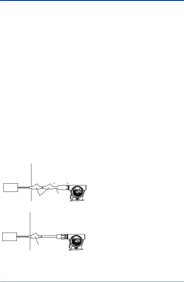
Note 2. Wiring
•All wiring shall comply with Canadian Electrical Code Part I and Local Electrical Codes.
•In hazardous location, wiring shall be in conduit as shown in the figure.
•WARNING:
ASEALSHALLBE INSTALLED WITHIN 50cm OF THE ENCLOSURE.
UN SCELLEMENT DOIT ÊTRE INSTALLÉ À MOINS DE 50cm DU BOÎTIER.
•WARNING:
WHEN INSTALLED IN CL.I, DIV 2, SEAL NOT REQUIRED.
UNE FOIS INSTALLÉ DANS CLI, DIV 2, AUCUN JOINT N'EST REQUIS.
Non-Hazardous |
Hazardous Locations Division 1 |
|||||||||
Locations |
|
|
|
|
|
|
|
|
|
|
Non-hazardous |
|
|
|
|
|
|
|
|
|
|
Location |
|
|
|
50 cm Max. |
||||||
Equipment |
|
|
|
|||||||
|
|
|
|
|
|
|
|
|
|
|
|
|
|
|
|
|
|
|
|
|
|
|
|
|
|
|
|
|
|
|
|
|
|
|
|
|
|
|
|
|
|
|
|
42 V DC Max. |
|
SUPPLY |
|
Sealing Fitting |
Conduit |
||
4 to 20 mA DC |
|||
Signal |
|
Transmitter |
|
|
|
||
|
|
F0205-1.ai |
Non-Hazardous Hazardous Locations Division 2
Locations
Non-hazardous
Location
Equipment
42 V DC Max. |
SUPPLY |
4 to 20 mA DC |
Sealing Fitting |
Signal |
Transmitter |
|
|
|
F0205-2.ai |
<2. Handling Cautions> |
2-7 |
•All wiring shall comply with local installation requirements and local electrical code.
•In hazardous locations, the cable entry devices shall be of a certified flameproof type, suitable for the conditions of use and correctly installed.
•Unused apertures shall be closed with suitable flameproof certified blanking elements. (The plug attached is flameproof certified.)
Note 3. Operation
•WARNING:
AFTER DE-ENERGIZING, DELAY 5 MINUTES BEFORE OPENING. APRÉS POWER-OFF,ATTENDRE 5 MINUTESAVANT D'OUVRIR.
•WARNING:
WHENAMBIENTTEMPERATURE ≥ 65°C, USE THE HEAT-RESISTING CABLES ≥ 90°C.
QUAND LATEMPÉRATUREAMBIANTE ≥ 65°C, UTILISEZ DES CÂBLES RÉSISTANTES Á LACHALEUR ≥ 90°C.
•Take care not to generate mechanical sparking when accessing to the instrument and peripheral devices in a hazardous location.
Note 4. Maintenance and Repair
•The instrument modification or parts replacement by other than authorized representative of Yokogawa Electric Corporation and Yokogawa Corporation of America is prohibited and will void Canadian Standards Explosionproof Certification.
cCSAIntrinsically Safe Type/CSA Explosionproof Type
Model EJX/EJA-E Series pressure transmitters with optional code /CU1 or /V1U1 can be selected the type of protection (CSAIntrinsically Safe or CSAExplosionproof) for use in hazardous locations.
Note 1. For the installation of this transmitter, once a particular type of protection is selected, any other type of protection cannot be used. The installation must be in accordance with the description about the type of protection in this instruction manual.
Note 2. In order to avoid confusion, unnecessary marking is crossed out on the label other than the selected type of protection when the transmitter is installed.
IM 01C25B01-01E
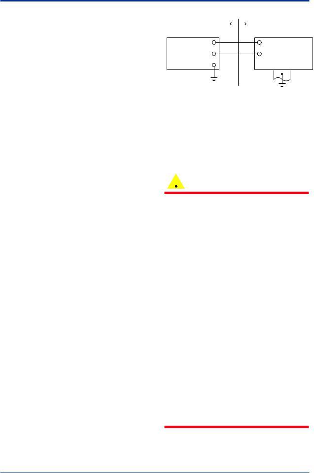
2.9.3 ATEX Certification
(1) Technical Data
a. ATEX Intrinsically Safe Ex ia
Caution forATEX Intrinsically safe type.
Note 1. Model EJX/EJA-E Series pressure transmitters with optional code /KS21 for potentially explosive atmospheres:
•No. DEKRA11ATEX0228 X
•Applicable Standard:
EN 60079-0:2009, EN 60079-11:2007, EN 60079-26:2007, EN 61241-11:2006
•Type of Protection and Marking code: Ex ia IIC T4 Ga
Ex ia IIIC T85 ºC T100 ºC T120 ºC Db
•Group: II
•Category: 1G, 2D
•Ambient Temperature for EPLGa: –50 to 60°C
•Ambient Temperature for EPLDb: –30* to 60°C
* –15°C when /HE is specified.
•Process Temperature (Tp.): 120°C max.
•Maximum Surface Temperature for EPLDb: T85°C (Tp.: 80°C)
T100°C (Tp.: 100°C) T120°C (Tp.: 120°C)
•Enclosure: IP66 / IP67
Note 2 Electrical Data
•In type of explosion protection intrinsic safety Ex ia IIC or Ex ia IIIC, only for connection to a certified intrinsically safe circuit with following maximum values:
Ui = 30 V Ii = 200 mA Pi = 0.9 W
(Linear Source)
Maximum internal capacitance; Ci = 27.6 nF Maximum internal inductance; Li = 0 µH
Note 3. Installation
•Refer to the control drawing.All wiring shall comply with local installation requirements.
<2. Handling Cautions> |
2-8 |
||||
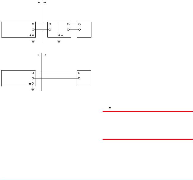
[Control Drawing] |
|
||||
Hazardous Location |
|
|
|
Nonhazardous Location |
|
|
|
||||
Transmitter |
|
+ |
+ |
Supply |
Safety Barrier *1 |
– |
– |
F0206.ai
*1: In any safety barriers used the output current must be limited by a resistor “R” such that Io=Uz/R.
Note 4. Maintenance and Repair
•The instrument modification or parts replacement by other than authorized representative of Yokogawa Electric Corporation is prohibited and will void DEKRAIntrinsically safe Certification.
Note 5. Special Conditions for Safe Use
 WARNING
•In the case where the enclosure of the Pressure Transmitter is made of aluminium, if it is mounted in an area where the use of category 1 G apparatus is required, it must be installed such, that, even in the event of rare incidents, ignition sources due to impact and friction sparks are excluded.
•Electrostatic charge may cause an exlosion hazard. Avoid any actions that cause the gerenation of eletrostatic charge, such as rubbing with a dry cloth on coating face of the product.
•In case of the enclosure of the Pressure Transmitter with paint layers, if it is mounted in an area where the use of category 2D apparatus is required, it shall be installed in such a way that the risk from electrostatic discharges and propagating brush discharges caused by rapid flow of dust is avoided.
•To satisfy IP66 or IP67, apply waterproof glands to the electrical connection port.
•When the lightning protector option is specified, the apparatus is not capable of withstanding the 500V insulation test
required by EN60079-11. This must be taken
into account when installing the apparatus.
IM 01C25B01-01E

<2. Handling Cautions> |
2-9 |
b. ATEX Flameproof Type
Caution forATEX flameproof type.
Note 1. Model EJX/EJA-E Series pressure transmitters with optional code /KF22 for potentially explosive atmospheres:
•No. KEMA07ATEX0109 X
•Applicable Standard: EN 60079-0:2009, EN 60079-1:2007, EN 60079-31:2009
•Type of Protection and Marking Code:
Ex d IIC T6...T4 Gb, Ex tb IIIC T85°C Db
•Group: II
•Category: 2G, 2D
•Enclosure: IP66 / IP67
•Temperature Class for gas-poof: T6, T5, and T4
•Ambient Temperature for gas-proof: –50 to 75°C (T6), –50 to 80°C (T5), and –50 to 75°C (T4)
•Maximum Process Temperature (Tp.) for gas-proof:
85°C (T6), 100°C (T5), and 120°C (T4)
•Maximum Surface Temperature for dustproof:
T85°C (Tamb.: –30* to 75°C, Tp.: 85°C)
* –15°C when /HE is specified.
Note 2. Electrical Data
•Supply voltage: 42 V dc max.
•Output signal: 4 to 20 mA
Note 3. Installation
•All wiring shall comply with local installation requirement.
•The cable entry devices shall be of a certified flameproof type, suitable for the conditions of use.
Note 4. Operation
•Keep the “WARNING” label attached to the transmitter.
WARNING:AFTER DE-ENERGIZING, DELAY 5 MINUTES BEFORE OPENING. WHEN THEAMBIENTTEMP.≥65°C, USE HEAT-RESISTING CABLEAND CABLE GLAND ≥90°C.
•Take care not to generate mechanical sparking when accessing to the instrument and peripheral devices in a hazardous location.
Note 5. Special Conditions for Safe Use
 WARNING
•Electrostatic charge may cause an exlosion hazard. Avoid any actions that cause the gerenation of eletrostatic charge, such as rubbing with a dry cloth on coating face of the product.
•In the case where the enclosure of the Pressure Transmitter is made of aluminium, if it is mounted in an area where the use of category 2D apparatus is required, it shall be installed in such a way that the risk from electrostatic discharges and propagating brush discharges caused by rapid flow of dust is avoided.
•The instrument modification or parts replacement by other than an authorized Representative of Yokogawa Electric Corporation is prohibited and will void the certification.
•To satisfy IP66 or IP67, apply waterproof glands to the electrical connection port.
c.ATEX Intrinsically Safe Type/ATEX Flameproof Type
Model EJX/EJA-E Series pressure transmitters with optional code /KU22 or /V1U1 can
be selected the type of protectionATEX Flameproof, Intrinsically Safe. Ex ia, or Ex ic for use in hazardous area.
Note 1. For the installation of this transmitter, once a particular type of protection is selected, any other type of protection cannot be used. The installation must be in accordance with the description about the type of protection in this user’s manual.
Note 2. For combined approval types Once a device of multiple approval type is installed, it should not be re-installed using any other approval types.Apply a permanent mark in the check box of the selected approval type on the certification label on the transmitter to distinguish it from unused approval types.
IM 01C25B01-01E
● ATEX Intrinsically Safe Ex ic
Caution forATEX intrinsically safe Ex ic
•Applicable Standard:
EN 60079-0:2009/EN 60079-0:2012, EN 60079-11:2012
•Type of Protection and Marking Code:  II 3G Ex ic IIC T4 Gc
•Ambient Temperature: –30* to +60°C
* –15°C when /HE is specified.
•Ambient Humidity:
0 to 100% (No condensation)
•Maximum Process Temperature: 120°C
•IP Code: IP66
•Ambient pollution degree: 2
•Overvoltage category: I
Note 1. Electrical Data
Ui = 30 V
Ci = 27.6 nF
Li = 0 µH
Note 2. Installation
•All wiring shall comply with local installation requirements. (refer to the control drawing)
•Cable glands, adapters and/or blanking elements shall be of Ex “n”, Ex “e” or Ex “d” and shall be installed so as to maintain the specified degree of protection (IP Code) of the transmitters.
Note 3. Maintenance and Repair
•The instrument modification or parts replacement by other than authorized representative of Yokogawa Electric Corporation is prohibited and will voidATEX intrinsically safe.
|
[Control drawing] |
||
Hazardous Area |
Nonhazardous Area |
||
|
+ |
Associated |
|
Transmitter |
– |
||
Apparatus |
|||
|
|||
F0207.ai
Note 4. Specific Conditions of Use
<2. Handling Cautions> |
2-10 |
 WARNING
•Electrostatic charge may cause an explosion hazard. Avoid any actions that cause the gerenation of eletrostatic charge, such as rubbing with a dry cloth on coating face of the product.
•When the lightning protector option is specified, the apparatus is not capable of withstanding the 500V insulation test
required by EN60079-11. This must be taken into account when installing the apparatus.
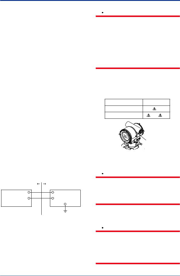
(2)Electrical Connection
Amark indicating the electrical connection type is stamped near the electrical connection port. These marks are as followed.
Screw Size |
Marking |
ISO M20 × 1.5 female |
M |
ANSI 1/2 NPT female |
N or W |
Location of the mark
F0208.ai
(3) Installation
 WARNING
•All wiring shall comply with local installation requirements and the local electrical code.
•There is no need for conduit seal in Division 1 and Division 2 hazardous locations because this product is sealed at the factory.
(4)Operation
 WARNING
•OPEN CIRCUIT BEFORE REMOVING COVER. INSTALLINACCORDANCE WITH THIS USER’S MANUAL
•Take care not to generate mechanical sparking when access to the instrument and peripheral devices in a hazardous location.
IM 01C25B01-01E
<2. Handling Cautions> |
2-11 |
|
|
(5) Maintenance and Repair
 WARNING
The instrument modification or parts replacement by other than an authorized Representative of Yokogawa Electric Corporation is prohibited and will void the certification.
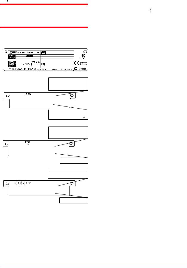
(6) Name Plate
Name plate
Tag plate for flameproof type
No. KEMA 07ATEX0109 X |
|
|
|
|
Ex d IIC T6...T4 Gb, |
Ex tb IIIC T85°C Db |
|
||
Enlcosure : IP66/IP67 |
T6 |
T5 |
T4 |
|
TEMP. CLASS |
|
|||
MAX PROCESS TEMP.(Tp.) |
85 |
100 |
120 °C |
|
Tamb. |
-50 to |
75 |
80 |
75 °C |
T85°C(Tamb.:-30(-15) to 75°C, Tp.:85°C)(for Dust)
*3
 D
D
WARNING
AFTER DE-ENERGIZING, DELAY 5 MINUTES BEFORE
OPENING.
WHEN THE AMBIENT TEMP. ≥ 65°C, USE THE
HEAT-RESISTING CABLE & CABLE GLAND ≥ 90°C
POTENTIAL ELECTROSTATIC CHARGING HAZARD
Tag plate for intrinsically safe type
No. DEKRA 11ATEX 0228 X
Ex ia IIC T4 Ga Ta: -50 TO 60°C
Ex ia IIIC T85°C T100°C T120°C Db Ta:-30(-15) TO 60°C |
|
IP66/IP67 |
120°C |
MAX. PROCESS TEMP.(Tp.) |
|
T85°C(Tp.:80°C), T100°C(Tp.:100°C), T120°C(Tp.:120°C) |
|
Ui=30V, Ii=200mA , Pi=0.9W, |
Ci=27.6nF, Li=0µH |
*3
 D
D
WARNING
POTENTIAL ELECTROSTATIC CHARGING HAZARD
- SEE USER’S MANUAL
Tag plate for intrinsically safe Ex ic
Ex ic IIC T4 Gc
IP66
Tamb -30(-15) TO 60°C
MAX. PROCESS TEMP. 120°C
Ui=30V, Ci=27.6nF, Li=0µH
WARNING
POTENTIAL ELECTROSTATIC CHARGING HAZARD
- SEE USER’S MANUAL
F0209.ai
MODEL: Specified model code.
STYLE: Style code.
SUFFIX: Specified suffix code.
SUPPLY: Supply voltage.
OUTPUT: Output signal.
MWP: Maximum working pressure.
CALRNG: Specified calibration range.
NO.: Serial number and year of production*1.
TOKYO 180-8750 JAPAN:
The manufacturer name and the address*2.
*1: The first digit in the three numbers next to the nine letters of the serial number appearing after “NO.” on the nameplate indicates the year of production. The following is an example of a serial number for a product that was produced in 2010:
91K819857 032
The year 2010
*2: “180-8750” is a zip code which represents the following address.
2-9-32 Nakacho, Musashino-shi, Tokyo Japan
*3: The identification number of Notified Body.
2.9.4 IECEx Certification
Model EJX Series pressure transmitters with optional code /SU2 can be selected the type of protection (IECEx Intrinsically Safe/type n or flameproof) for use in hazardous locations.
Note 1. For the installation of this transmitter, once a particular type of protection is selected, any other type of protection cannot be used. The installation must be in accordance with the description about the type of protection in this instruction manual.
Note 2. In order to avoid confusion, unnecessary marking is crossed out on the label other than the selected type of protection when the transmitter is installed.
a. IECEx Intrinsically Safe Type / type n
Caution for IECEx Intrinsically safe and type n.
Note 1. Model EJX Series differential, gauge, and absolute pressure transmitters with optional code /SU2 are applicable for use in hazardous locations
•No. IECEx CSA05.0005
•Applicable Standard: IEC 60079-0:2000, IEC 60079-11:1999, IEC 60079-15:2001
•Ex ia IIC T4, Ex nLIIC T4
•Ambient Temperature: –50 to 60°C
•Max. Process Temp.: 120°C
•Enclosure: IP66/IP67
Note 2. Entity Parameters
•Intrinsically safe ratings are as follows: Maximum Input Voltage (Vmax/Ui) = 30 V Maximum Input Current (Imax/Ii) = 200 mA Maximum Input Power (Pmax/Pi) = 0.9 W Maximum Internal Capacitance (Ci) = 10 nF Maximum Internal Inductance (Li) = 0 µH
•Type "n" ratings are as follows: Maximum Input Voltage (Vmax/Ui) = 30 V
Maximum Internal Capacitance (Ci) = 10 nF Maximum Internal Inductance (Li) = 0 µH
IM 01C25B01-01E
<2. Handling Cautions> |
2-12 |
|
|
•Installation Requirements Uo ≤ Ui, Io ≤ Ii, Po ≤ Pi,
Co ≥ Ci + Ccable, Lo ≥ Li + Lcable Voc ≤ Vmax, Isc ≤ Imax,
Ca ≥ Ci + Ccable, La ≥ Li + Lcable
Uo, Io, Po, Co, Lo, Voc, Isc, Ca and La are parameters of barrier.
Note 3. Installation
•In any safety barrier used output current must be limited by a resistor 'R' such that Io=Uo/R.
•The safety barrier must be IECEx certified.
•Input voltage of the safety barrier must be less than 250 Vrms/Vdc.
•The instrument modification or parts replacement by other than authorized representative of Yokogawa Electric Corporation and will void IECEx Intrinsically safe and type n certification.
|
[Intrinsically Safe] |
|
|
|
Hazardous Location |
Nonhazardous Location |
|||
Group IIC, Zone 0 |
|
|
|
General |
|
|
IECEx certified |
||
|
|
Purpose |
||
Pressure Transmitters |
Safety Barrier |
Equipment |
||
|
+ |
+ |
+ |
+ |
Supply |
– |
– |
– |
– |
|
|
|
|
F0210-1.ai |
|
|
[type n] |
|
|
Hazardous Location |
Nonhazardous Location |
|||
Group IIC, Zone 2 |
|
|
IECEx Certified |
|
Pressure Transmitters |
|
|
||
|
|
Equipment [nL] |
||
|
+ |
|
|
+ |
Supply |
– |
Not Use |
|
– |
|
|
|
|
|
|
|
Safety Barrier |
|
|
|
|
|
|
F0210-2.ai |
b. IECEx Flameproof Type
Caution for IECEx flameproof type.
Note 1. Model EJX/EJA-E Series pressure transmitters with optional code /SF2 or /SU2 are applicable for use in hazardous locations:
•No. IECEx CSA07.0008
•Applicable Standard: IEC60079-0:2004, IEC60079-1:2003
•Flameproof for Zone 1, Ex d IIC T6...T4
•Enclosure: IP66/IP67
•Maximum Process Temperature: 120°C (T4), 100°C (T5), 85°C (T6)
•Ambient Temperature: –50 to 75°C (T4), –50 to 80°C (T5), –50 to 75°C (T6)
•Supply Voltage: 42 V dc max.
•Output Signal: 4 to 20 mAdc
Note 2. Wiring
•In hazardous locations, the cable entry devices shall be of a certified flameproof type, suitable for the conditions of use and correctly installed.
•Unused apertures shall be closed with suitable flameproof certified blanking elements.
Note 3. Operation
•WARNING:
AFTER DE-ENERGIZING, DELAY 5 MINUTES BEFORE OPENING.
•WARNING:
WHENAMBIENTTEMPERATURE ≥ 65°C, USE THE HEAT-RESISTING CABLES ≥ 90°C.
•Take care not to generate mechanical sparking when accessing to the instrument and peripheral devices in a hazardous location.
Note 4. Maintenance and Repair
•The instrument modification or parts replacement by other than authorized representative of Yokogawa Electric Corporation is prohibited and will void IECEx Certification.
2.10 EMC Conformity Standards
EN61326-1 ClassA,Table2 (For use in industrial locations)
EN61326-2-3
 CAUTION
To meet EMC regulations, Yokogawa recommends that customers run signal wiring through metal conduits or use shielded twistedpair cabling when installing EJX/EJA-E series transmitters in a plant.
IM 01C25B01-01E
<2. Handling Cautions> |
2-13 |
2.11Pressure Equipment Directive (PED)
(1) General
•EJX/EJA-E Series pressure transmitters are categorized as piping under the pressure accessories section of directive 97/23/EC, which corresponds toArticle 3, Paragraph 3 of PED, denoted as Sound Engineering Practice (SEP).
•EJX110A-MS, EJX110A-HS, EJX110A-VS, EJ130, EJ440, and EJA110E with /HG can be used above 200 bar and therefore considered as a part of a pressure retaining vessel where category III, Module H applies. These models with option code /PE3 conform to that category.
(2) Technical Data
•Models without /PE3
Article 3, Paragraph 3 of PED, denoted as Sound Engineering Practice (SEP).
•Models with /PE3 Module: H
Type of Equipment: PressureAccessory-Vessel Type of fluid: Liquid and Gas
Group of fluid: 1 and 2
Model |
Capsule |
PS*1 |
V(L) |
PS.V |
Category*2 |
|
code |
(bar) |
(bar.L) |
||||
EJA110E |
M, H, V |
160 |
0.01 |
1.6 |
|
|
|
|
|
||||
EJ110 |
F, L |
Article 3, |
||||
|
|
|
||||
|
|
|
|
|
||
|
|
|
|
|
||
EJX110A |
|
|
|
|
Paragraph 3 |
|
|
|
|
|
|
(SEP) |
|
EJA110E |
M, H, V |
250 |
0.01 |
2.5 |
||
|
||||||
with code |
|
|
|
|
|
|
/HG |
|
|
|
|
|
|
EJ110 |
M, H, V |
250 |
0.01 |
2.5 |
III |
|
with code |
||||||
/PE3 |
|
|
|
|
|
|
|
|
|
|
|
Article 3, |
|
EJ130 |
M, H |
500 |
0.01 |
5.0 |
Paragraph 3 |
|
|
|
|
|
|
(SEP) |
|
EJ130 |
M, H |
500 |
0.01 |
5.0 |
III |
|
with code |
||||||
/PE3 |
|
|
|
|
|
|
|
|
|
|
|
Article 3, |
|
EJ310 |
L, M,A, B |
160 |
0.01 |
1.6 |
Paragraph 3 |
|
|
|
|
|
|
(SEP) |
|
|
|
|
|
|
Article 3, |
|
EJ430 |
H,A, B |
160 |
0.01 |
1.6 |
Paragraph 3 |
|
|
|
|
|
|
(SEP) |
|
|
|
|
|
|
Article 3, |
|
EJ440 |
C, D |
500 |
0.1 |
5.0 |
Paragraph 3 |
|
|
|
|
|
|
(SEP) |
|
EJ440 |
C, D |
500 |
0.1 |
5.0 |
III |
|
with code |
||||||
/PE3 |
|
|
|
|
|
*1: PS is maximum pressure for vessel itself based on Pressure Equipment Directive 97/23/EC. Refer to General Specification for maximum working pressure of a transmitter.
*2: Referred to Table 1 covered byANNEX II of EC Directive on Pressure Equipment Directive 97/23/EC
(3) Operation
 CAUTION
•The temperature and pressure of fluid should be maintained at levels that are consistent with normal operating conditions.
•The ambient temperature should be maintained at a level that is consistent with normal operating conditions.
•Please take care to prevent water hammer and the like from inducing excessive pressures in pipes and valves. If phenomena are likely, install a safety valve or take some other appropriate measure to prevent pressure from exceeding PS.
•Take appropriate measures at the device or system level to protect transmitters if they are to be operated near an external heat source.
2.12 Low Voltage Directive
Applicable standard: EN61010-1
(1) Pollution Degree 2
"Pollution degree" describes the degree to which a solid, liquid, or gas which deteriorates dielectric strength or surface resistivity is adhering. " 2 " applies to normal indoor atmosphere. Normally, only non-conductive pollution occurs. Occasionally, however, temporary conductivity caused by condensation must be expected.
(2) Installation Category I
"Overvoltage category (Installation category)" describes a number which defines a transient overvoltage condition. It implies the regulation for impulse withstand voltage. " I " applies to electrical equipment which is supplied from the circuit when appropriate transient overvoltage control means (interfaces) are provided.
IM 01C25B01-01E
<3. Component Names> |
3-1 |
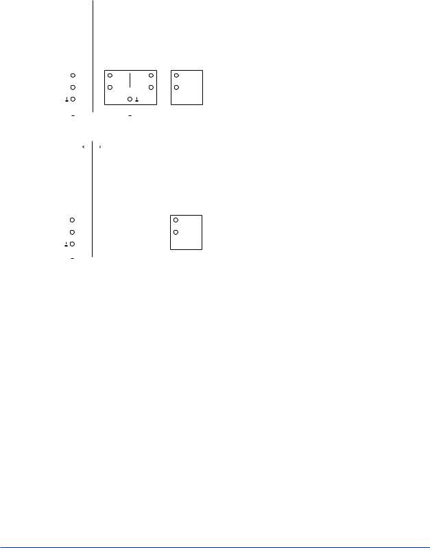
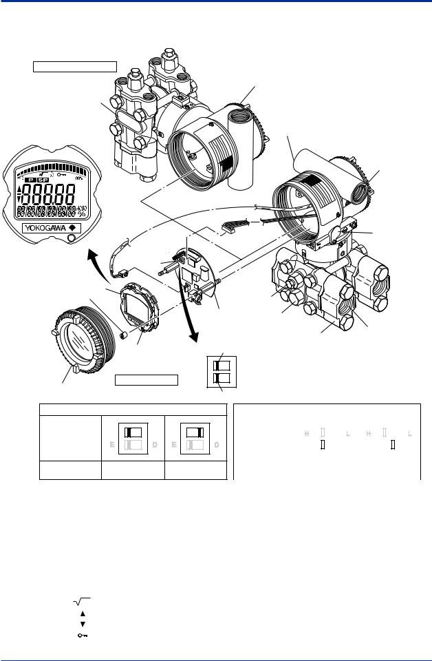
3.Component Names
Vertical impulse piping type
Pressure-detector section
Terminal box cover
Cover flange
Horizontal impulse piping type
External indicator conduit connection (Note 1)
Conduit connection
|
|
|
Zero- |
|
|
|
adjustment |
(Note 2) |
|
|
screw |
|
|
|
|
Integral |
|
|
|
indicator (Note 1) |
|
|
|
Mounting screw |
|
Vent plug |
|
|
CPU assembly Drain plug |
|
|
|
|
Process |
Process |
|
|
connection |
|
|
|
connector (Note 1) |
|
Range-setting |
|
|
|
Burnout direction switch |
|
||
switch (Note 1) |
|
|
|
(See section 7.6) |
BO H |
L |
|
|
|
||
Transmitter section |
WR E |
D |
|
Amplifier Cover |
Write protection switch |
|
|
|
|
||
Burnout direction switch (BO)
Burnout Direction |
H |
L |
H |
L |
Switch Position |
|
|
|
|
Burnout Direction |
|
HIGH |
|
LOW |
Hardware write protection switch (WR)
Write Protection |
|
H |
|
|
|
|
|
|
L |
|
|
H |
|
|
|
|
|
|
|
L |
|
|
|
|
|
|
|
|
|
|
|
|
|
|
|
|
|
|
|
||||||
|
|
|
|
|
|
|
|
|
|
|
|
|
|
|
|
|
||||||
Switch Position |
E |
|
|
|
|
D |
E |
|
|
|
|
|
D |
|||||||||
|
|
|
|
|
|
|
|
|
||||||||||||||
|
|
|
|
|
|
|
|
|
|
|||||||||||||
|
|
|
|
|
|
|
|
|
|
|
|
|
|
|
|
|
|
|
|
|
|
|
|
|
|
|
|
|
|
|
|
|
|
||||||||||||
Write Protection |
|
|
|
|
NO |
|
|
|
|
YES |
||||||||||||
(Write enabled) |
(Write disabled) |
|||||||||||||||||||||
|
||||||||||||||||||||||
F0301.ai
Note 1: See subsection 9.2, “Model and Suffix Codes,” for details.Aprocess connector will not be applied for lower side of EJ310,
EJ430, and EJ440.
Note 2: Applicable for BRAIN/HART communication type. Set the switches as shown in the figure above to set the burn-out direction
and write protection. The Burnout switch is set to the H side for delivery (unless option code /C1 or /C2 is specified in the order),
and the hardware write protection switch is set to E side. The setting of the switches can be confirmed via communication.An
external zero adjustment screw can only be disabled by communication. To disable the screw, set a parameter before activating
the hardware write protect function. See each communication manual.
Figure 3.1 Component Names
Table 3.1 |
Display Symbol |
|
|
|
|
Display Symbol |
Meaning of Display Symbol |
|
|
|
Display mode is ‘square root’. (Display is not lit when ‘linear’ mode.) |
|
|
|
The output signal being zero-adjusted is increasing. |
|
|
|
The output signal being zero-adjusted is decreasing. |
|
|
|
Write protect function is enabled. |
F0302.ai
IM 01C25B01-01E
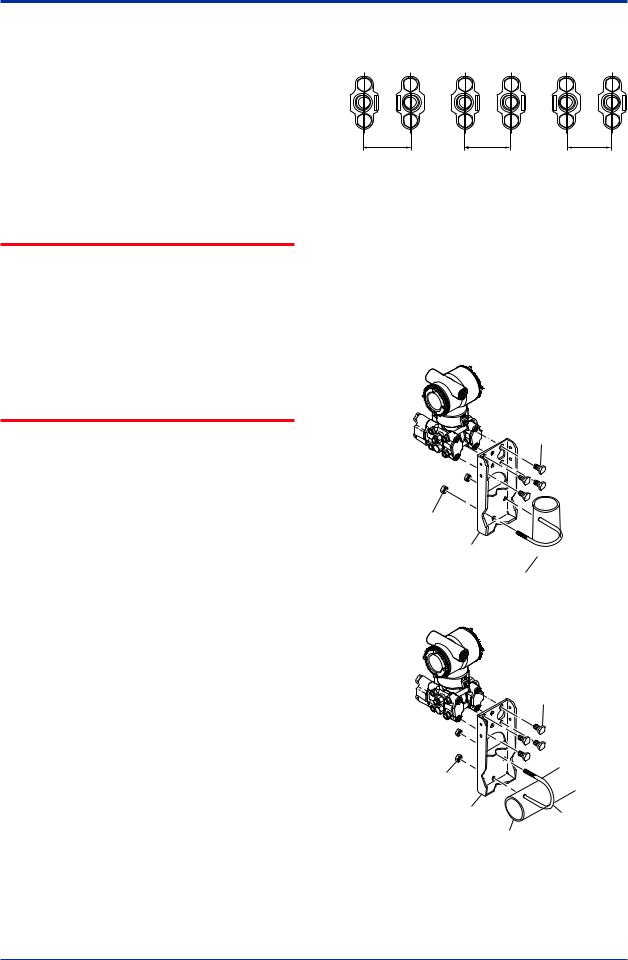
<4. Installation> |
4-1 |
4.Installation
4.1Precautions
Before installing the transmitter, read the cautionary notes in section 2.4, “Selecting the Installation Location.” For additional information on the ambient conditions allowed at the installation location, refer to subsection 9.1 “Standard Specifications.”
 IMPORTANT
•When welding piping during construction, take care not to allow welding currents to flow through the transmitter.
•Do not step on this instrument after installation.
•For the EJ430and EJ440, the atmospheric opening is located on the low pressure side cover flange. The opening must not face upward. See section 9.4, “Dimensions,” for the location of the opening.
4.2Mounting
■The transmitter is shipped with the process connection, according to the ordering specifications. To change the orientation of the process connections, refer to section 4.3.
■With differential pressure transmitters, the distance between the impulse piping
connection ports is usually 54 mm (figure 4.1). By changing the orientation of the process connector, the dimension can be changed to 51 mm or 57 mm.
■The transmitter can be mounted on a nominal 50 mm (2-inch) pipe using the mounting bracket supplied, as shown in figure 4.2 and 4.3 The transmitter can be mounted on either a horizontal or a vertical pipe.
■When mounting the bracket on the transmitter, tighten the (four) bolts that hold the transmitter with a torque of approximately 39 N·m {4kgf·m}.
57 mm 54 mm 51 mm
F0401.ai
Figure 4.1 Process Connector Impulse Piping Connection Distances for Differential Pressure Transmitters
Figure 4.1 and 4.2 shows the mounting of the transmitter for horizontal piping and vertical piping with using the mounting bracket. The transmitters with the installation code -U (Universal flange) can be used for either type of mounting.
Vertical pipe mounting
Transmitter mounting bolt
U-bolt nut
Mounting bracket U-bolt

 50 mm(2-inch) pipe
Horizontal pipe mounting
Transmitter mounting bolt
U-bolt nut |
|
|
Mounting bracket |
U-bolt |
|
|
|
|
50 mm(2-inch) pipe |
F0402.ai |
|
|
|
|
Figure 4.2 Transmitter Mounting (Horizontal
Impulse Piping Type)
IM 01C25B01-01E
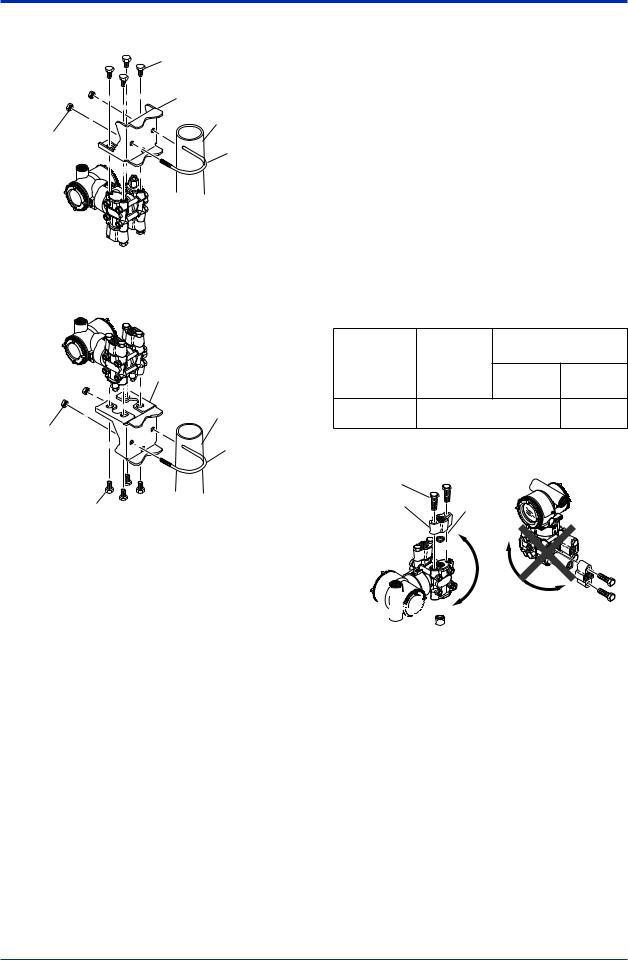
<4. Installation> |
4-2 |
Vertical pipe mounting (Process connector downside)
Transmitter mounting bolt
Mounting bracket
50 mm(2-inch) pipe
U-bolt nut
U-bolt
Vertical pipe mounting (Process connector upside)
|
Mounting bracket |
|
50 mm(2-inch) pipe |
U-bolt nut |
U-bolt |
|
|
Transmitter |
|
mounting bolt |
F0403.ai |
Figure 4.3 Transmitter Mounting (Vertical Impulse
Piping Type)
4.3Changing the Process Connection
The transmitter is shipped with the process connection specified at the time of ordering. To change the process connection, the drain (vent) plug must be repositioned.
To reposition a drain (vent) plug, use a wrench to slowly and gently unscrew it. Then, remove and remount it on the opposite side. Wrap sealing tape around the drain (vent) plug threads (*1 in the figure below), and apply a lubricant to the threads of the drain (vent) screw(s) (*2 below). To tighten the drain (vent) plugs, apply a torque of 34 to 39 N·m (3.5 to 4 kgf·m). Process connector bolts are to be tightened uniformly to a torque shown in table 4.1.
Table 4.1 |
Torque |
|
|
|
|
EJ110 |
|
EJ440 |
|
Model |
EJ120 |
|
||
EJ130 |
|
|
||
|
EJ310 |
C capsule D capsule |
||
|
EJ430 |
|
|
|
Torque(N·m) |
39 to 49 {4 to 5} |
49 to 59 |
||
{kgf·m} |
{5 to 6} |
|||
|
|
|||
Vertical impulse piping type |
Horizontal impulse piping type |
|||
Bolt |
|
|
|
|
Process |
gasket |
|
||
connector |
|
|||
|
|
|
||


 *1
*1
Drain/vent plug 
 *2 Note: For a horizontal impulse piping type, moving the
process connectors from the front side to the back cannot be made.
F0404.ai
Figure 4.4 Changing Process Connection
IM 01C25B01-01E
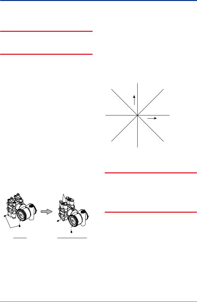
<4. Installation> |
4-3 |
4.4Swapping the High/Lowpressure Side Connection
 IMPORTANT
This section is applicable only for EJ110, EJ120, and EJ130differential transmitters, and not applicable for gauge or absolute pressure transmitters.
4.4.1Rotating Pressure-detector Section 180°
This procedure can be applied only to a transmitter with a vertical impulse piping type.
The procedure below can be used to turn the pressure detector assembly 180°. Perform this operation in a maintenance shop with the
necessary tools laid out and ready for use, and then install the transmitter in the field after making the change.
1)Use anAllen wrench (JIS B4648, nominal 2.5 mm) to remove the two setscrews at the joint between the pressure-detector section and transmitter section.
2)Leaving the transmitter section in position, rotate the pressure-detector section 180°.
3)Tighten the two setscrews to fix the pressuredetector section and transmitter section together (at a torque of 1.5 N·m). Reposition the process connector and drain
(vent) plugs to the opposite side as described in subsection 4.3.
Process connector
Setscrew |
|
Before |
After rotating 180° |
|
F0405.ai |
Figure 4.5 Before andAfter Modification
4.4.2 Using the Communicator
This method is applicable only to the Model EJ110, EJ120, and EJ130.
With a communicator, you can change which process connection is used as the high-pressure side without mechanically rotating the pressuredetector section 180 as described in subsection 4.4.1. To change, call parameter ‘D15: H/LSWAP’ for BRAIN Communication or ‘H/Lswap’for HART Communication and select REVERSE (right side: low pressure; left side: high pressure) or select NORMALto change back to normal (right side: high pressure; left side: low pressure).
NORMAL |
Output |
Input |
REVERSE |
F0406.ai
Figure 4.6 Input/Output Relationship
 IMPORTANT
Since the H/Llabel plate on the capsule assembly will remain unchanged, use this function only when you cannot switch the impulse piping. If the ‘H/LSWAP’parameter setting is changed, the input/output relationship is reversed as shown in figure 4.6; be sure this is understood by all.
IM 01C25B01-01E
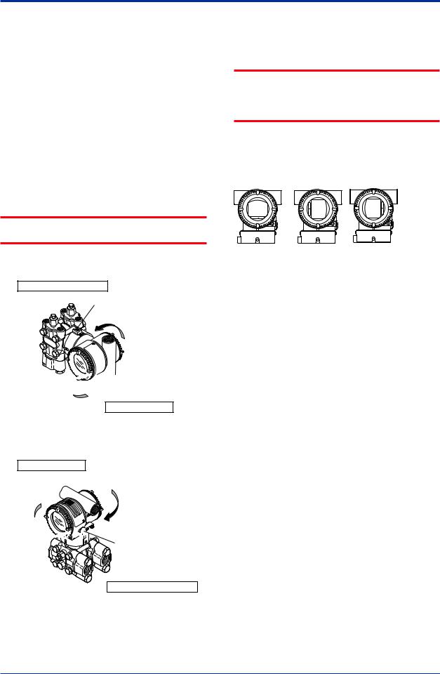
<4. Installation> |
4-4 |
4.5Rotating Transmitter Section
The transmitter section can be rotated approximately 360° (180° to either direction or 360° to one direction from the original position at shipment, depending on the configuration of the instrument.) It can be fixed at any angle within above range.
1)Remove the two setscrews that fasten the transmitter section and capsule assembly, using theAllen wrench.
2)Rotate the transmitter section slowly and stop it at designated position.
3)Tighten the two setscrews to a torque of 1.5 N·m.
 IMPORTANT
Do not rotate the transmitter section more than the above limit.
Vertical impulse piping type
Pressure-detector section
Stopper
Rotate 0 to ±180° segments


 Conduit connection
Transmitter section
Horizontal impulse piping type
Transmitter section
Rotate 0 to ±180° segments


 Conduit connection
Zero-adjustment screw
Pressure-detector section
F0407.ai
Figure 4.7 Rotating Transmitter Section (Left Side
High Pressure Type)
4.6Changing the Direction of Integral Indicator
 IMPORTANT
Always turn OFF power, release pressure and remove a transmitter to non-hazardous area before disassembling and reassmbling an indicator.
An integral indicator can be installed in the following three directions. Follow the instructions in section 8.4 for removing and attaching the integral indicator.
F0408.ai
Figure 4.8 Integral Indicator Direction
IM 01C25B01-01E
Loading...