


 Loading...
Operation
Guide
Model 436101/436102/436103/436104/436106
µR10000 Recorder
IM 04P01B01-02E
12th Edition
Yokogawa Electric Corporation
User Registration Request
Thank you for purchasing YOKOGAWA products.
Please register to the following Partner Portal Member Site.
You can use various services such as confirmation of purchased product information, download of related materials, and newsletter.
https://partner.yokogawa.com/global/
PRS 108-02E

Contents |
|
Introduction................................................................................................................................................................. |
4 |
Safety Precautions..................................................................................................................................................... |
4 |
Handling Precautions................................................................................................................................................. |
5 |
SD Memory Card Handling Precautions.................................................................................................................... |
5 |
How to Use This Manual............................................................................................................................................ |
6 |
Checking the Contents of the Package...................................................................................................................... |
6 |
Recorder Style Number, Release Number, and Firmware Version Number.............................................................. |
7 |
Removing the Packing Materials................................................................................................................................ |
7 |
Recorder’s Version and Functions Described in This Manual.................................................................................... |
8 |
Protection of Environment.......................................................................................................................................... |
9 |
Function Introduction/Names of Parts....................................................................................................................... |
10 |
Function Introduction................................................................................................................................................ |
10 |
Names of Parts......................................................................................................................................................... |
11 |
Display and Key Panel............................................................................................................................................. |
12 |
Installing/Wiring the Recorder.................................................................................................................................... |
13 |
Installation Location.................................................................................................................................................. |
13 |
Installation Procedure............................................................................................................................................... |
13 |
Input Signal Wiring................................................................................................................................................... |
16 |
Optional Terminal Wiring.......................................................................................................................................... |
18 |
Power Supply Wiring................................................................................................................................................ |
20 |
Common Operations and Menu Structure................................................................................................................. |
22 |
Execution Modes...................................................................................................................................................... |
22 |
Operation Sequence................................................................................................................................................ |
22 |
Key Operation.......................................................................................................................................................... |
23 |
Menu Structure of Setting Mode............................................................................................................................... |
26 |
Menu Structure of Basic Setting Mode..................................................................................................................... |
27 |
Preparing to Record..................................................................................................................................................... |
28 |
Loading or Replacing the Chart Paper..................................................................................................................... |
28 |
Installing/Replacing Felt Pens (Pen Model)............................................................................................................. |
30 |
Installing/Replacing the Plotter Pen (Pen Model)..................................................................................................... |
31 |
Installing/Replacing the Ribbon Cassette (Dot Model)............................................................................................. |
31 |
Checking or Setting the Date/Time........................................................................................................................... |
33 |
Setting the Input Range and Alarm on Measurement Channels............................................................................. |
34 |
Setup Example (1) of Thermocouple Input............................................................................................................... |
34 |
Setup Example (2) of 1-5V Input and unit................................................................................................................ |
35 |
Setup Example (3) of 0 to 10 V Input....................................................................................................................... |
37 |
Setting the Alarm...................................................................................................................................................... |
40 |
Recording/Displaying Data......................................................................................................................................... |
42 |
Starting the Recording.............................................................................................................................................. |
42 |
Stopping the Recording............................................................................................................................................ |
42 |
Feeding the Chart Paper Manually........................................................................................................................... |
42 |
Changing the Chart Speed....................................................................................................................................... |
43 |
Viewing the Recorded Results................................................................................................................................. |
43 |
Description of the Printout Contents......................................................................................................................... |
44 |
Switching the Display Screen................................................................................................................................... |
46 |
Changing the Displayed Information........................................................................................................................ |
47 |
FUNC Key Operations in Operation Mode............................................................................................................... |
48 |
Printing Measured Values (Manual Printout)............................................................................................................ |
48 |
Printing the Recorder Settings................................................................................................................................. |
49 |
Clearing the Alarm Printout Buffer............................................................................................................................ |
50 |
Printing a Message................................................................................................................................................... |
50 |
Releasing the Alarm Output (Alarm ACK Operation)................................................................................................ |
51 |
Activating/Releasing the Key Lock........................................................................................................................... |
51 |
Setup Items and Default Values.................................................................................................................................. |
52 |
Setup Items in Setting Mode and Their Default Values............................................................................................ |
52 |
Setup Items in Basic Setting Mode and Their Default Values.................................................................................. |
54 |
Recommended Replacement Periods for Worn Parts.............................................................................................. |
57 |
For detailed explanation of functions and the operating procedures of the recorder, see the µR10000 Recorder User’s Manual (IM 04P01B01-01E).
IM 04P01B01-02E |
3 |

Introduction |
|
|
License to copy and use this software is granted provided that it is iden- |
|||||
|
|
tified as the “RSA Data Security, Inc. MD5 Message-Digest Algorithm” in |
||||||
|
Thank you for purchasing the YOKOGAWA µR10000 Recorder. |
all material mentioning or referencing this software or this function. |
||||||
|
This manual describes concisely the operating procedures of the |
|||||||
|
License is also granted to make and use derivative works provided |
|||||||
|
µR10000 Recorder. To ensure correct use, please read this manual |
|||||||
|
that such works are identified as “derived from the RSA Data Secu- |
|||||||
|
and the following manuals thoroughly before beginning operation. |
|||||||
|
rity, Inc. MD5 Message-Digest Algorithm” in all material mentioning |
|||||||
|
For the product specifications, see the general specifications. |
|||||||
|
or referencing the derived work. |
|
|
|||||
• |
Paper Manuals |
|
|
|
|
|||
|
|
RSA Data Security, Inc. makes no representations concerning |
||||||
|
Manual Title |
Manual No.* |
either the merchantability of this software or the suitability of this |
|||||
|
μR10000 Recorder Operation Guide |
IM 04P01B01-02E (this manual) |
software for any particular purpose. It is provided “as is” without |
|||||
|
μR10000 /μR20000 Usage Precautions1 |
IM 04P01B01-93E |
express or implied warranty of any kind. |
|
||||
|
1 Only delivered when the Operation Guide is not included. |
These notices must be retained in any copies of any part of this |
||||||
• |
Electronic Manuals |
|
|
documentation and/or software. |
|
|
||
|
You can download these manuals from the following web page. You |
Trademarks |
|
|
|
|||
|
will need Adobe Reader 7 or later (latest version recommended) by |
|
|
|
||||
|
• All the brands or names of Yokogawa Electric’s products used |
|||||||
|
Adobe Systems. |
|
|
|||||
|
|
|
in this manual are either trademarks or registered trademarks of |
|||||
|
http://www.yokogawa.com/ns/mr/im/ |
|
||||||
|
|
Yokogawa Electric Corporation. |
|
|
||||
|
Manual Title |
|
Manual No.* |
• Microsoft and Windows are either registered trademarks or |
||||
|
μR10000 Recorder Operation Guide |
|
IM 04P01B01-02E |
trademarks of Microsoft Corporation in the United States and/or |
||||
|
μR10000 Recorder User’s Manual |
|
IM 04P01B01-01E |
other countries. |
|
|
||
|
μR10000/μR20000 Communication Interface |
IM 04P01B01-17E |
• Adobe, Acrobat, and PostScript are trademarks of Adobe Sys- |
|||||
|
User’s Manual |
|
|
tems Incorporated. |
|
|
||
|
|
|
• The SD logo is a registered trademark of the SD association. |
|||||
|
μR10000/μR20000 SD Memory Card (/EM1 |
|
IM 04P01B01-03E |
|||||
|
|
• For purposes of this manual, the TM and ® symbols do not |
||||||
|
option) User’s Manual |
|
|
|||||
|
|
|
accompany their respective trademark names or registered |
|||||
|
RXA10-01 and RXA10-02 Configuration |
|
IM 04P01B01-61E |
trademark names. |
|
|
||
|
Software User’s Manual (sold separately) |
|
|
• Company and product names that appear in this manual are |
||||
• |
General Specifications (GS) |
|
|
trademarks or registered trademarks of their respective holders. |
||||
|
|
Revisions |
|
|
|
|||
|
General Specifications Name |
|
General Specifications No.* |
|
|
|
||
|
|
|
|
1st Edition |
December |
10th Edition |
February 2020 |
|
|
μR10000 Recorder |
|
GS04P01B01-01E |
|||||
|
|
2nd Edition |
March 2005 |
11th Edition |
June 2020 |
|||
|
|
|
|
|||||
|
* The last character of the manual number and general specifi- |
3rd Edition |
August 2005 |
12th Edition |
February 2021 |
|||
|
cations number indicates the language in which the manual is |
4th Edition |
September 2006 |
|
|
|||
|
written. |
|
|
5th Edition |
April 2011 |
|
|
|
Notes |
|
|
6th Edition |
March 2015 |
|
|
||
|
• The contents of this manual are subject to change without prior |
7th Edition |
July 2017 |
|
|
|||
|
8th Edition |
June 2018 |
|
|
||||
|
notice as a result of continuing improvements to the instrument’s |
|
|
|||||
|
performance and functions. |
|
|
9th Edition |
September 2018 |
|
|
|
|
• Every effort has been made in the preparation of this manual to |
Authorised Representative in the EEA |
|
|||||
|
ensure the accuracy of its contents. However, should you have |
The Authorised Representative for this product in the EEA is: |
||||||
|
any questions or find any errors, please contact your nearest |
|||||||
|
Yokogawa Europe B.V. |
|
|
|||||
|
YOKOGAWA dealer as listed on the back cover of this manual. |
|
|
|||||
|
Euroweg 2, 3825 HD Amersfoort,The Netherlands |
|||||||
|
• Copying or reproducing all or any part of the contents of this |
|||||||
|
Safety Precautions |
|
|
|||||
|
manual without the permission of Yokogawa Electric Corporation |
|
|
|||||
|
is strictly prohibited. |
|
|
The general safety precautions described here must be observed |
||||
|
• The TCP/IP software of this product and the document con- |
during all phases of operation. |
|
|
||||
|
cerning the TCP/IP software have been developed/created by |
• Safety Standards and EMC Standards |
|
|||||
|
YOKOGAWA based on the BSD Networking Software, Release |
This recorder conforms to IEC safety class I (provided with terminal |
||||||
|
1 that has been licensed from the University of California. |
for protective grounding), Overvoltage Category II or I*1, Pollution |
||||||
QR Code |
|
|
Degree 2, Measurement Category II (CAT II)*2, and EN61326-1 |
|||||
|
The product has a QR Code pasted for efficient plant maintenance |
(EMC standard) class A (use in a commercial, industrial, or busi- |
||||||
|
work and asset information management. |
ness environment). The influence rate (judgment condition A) in the |
||||||
|
It enables confirming the specifications of purchased products and |
immunity test environment is within ±10 % of the range. |
||||||
|
user’s manuals. |
|
|
This recorder is designed for indoor use. |
|
|||
|
For more details, please refer to the following URL. |
*1 II : Applied to standard power supply (100-240 VAC), I: Applied |
||||||
|
https://www.yokogawa.com/qr-code |
|
to /P1 option (24 VDC/AC) |
|
|
|||
|
QR Code is a registered trademark of DENSO WAVE INCORPO- |
*2 Measurement Category II (CAT II) applies to measuring circuits |
||||||
|
connected to low voltage installation, and electrical instruments |
|||||||
|
RATED. |
|
|
|||||
|
|
|
supplied with power from fixed equipment such as electric |
|||||
About the Usage of Open Source Software |
||||||||
switchboards. |
|
|
||||||
|
MD5 |
|
|
• About This Manual |
|
|
||
|
The following products uses MD5 source code. |
• This manual should be read by the end user. |
|
|||||
|
In accordance with the MD5 license agreement, the copyright |
• Read this manual thoroughly and have a clear understanding of |
||||||
|
notice, redistribution conditions, and license are listed below. |
the product before operation. |
|
|
||||
|
• This manual explains the functions of the product.YOKOGAWAdoes |
|||||||
|
|
|
|
|||||
|
436101, 436102, 436103, 436104, 436106 |
not guarantee that the product will suit a particular purpose of the user. |
||||||
|
• RSA Data Security’s MD5 License |
|
|
• Under absolutely no circumstances may the contents of this manual |
||||
|
|
|
be transcribed or copied, in part or in whole, without permission. |
|||||
|
RSA Data Security, Inc., MD5 message-digest algorithm |
• The contents of this manual are subject to change without priornotice. |
||||||
|
• Every effort has been made in the preparation of this manual to |
|||||||
|
Copyright (C) 1991-2, RSA Data Security, Inc. Created 1991. All |
|||||||
|
ensure the accuracy of its contents. However, should you have |
|||||||
|
rights reserved. |
|
|
any questions or find any errors or omissions, please contact |
||||
|
|
|
|
your nearest YOKOGAWA dealer. |
|
|
||
12th Edition: February 2021 (YK) |
|
|
• Precautions Related to the Protection, Safety, and Alteration of |
|||||
All Rights Reserved, Copyright © 2004, Yokogawa Electric Corporation |
the Product |
|
|
|
||||
|
|
|
|
|
|
|
|
|
4 |
|
|
|
|
|
|
IM 04P01B01-02E |
|
|
• The following safety symbols are used on the product and in this |
Portable Type (/H5x Option) |
|||||||||||||||||
|
|
manual. |
• Use the Correct Power Supply |
||||||||||||||||
|
|
|
|
|
|
|
|
|
|
|
|
“Handle with care.” To avoid injury and damage |
|
Ensure that the power supply is within the maximum rated volt- |
|||||
|
|
|
|
|
|
|
|
|
|
|
|
to the instrument, the operator must refer to the |
|
age range of the provided power cord before connecting the |
|||||
|
|
|
|
|
|
|
|
|
|
|
|
explanation in the manual. |
|
power cord. |
|||||
|
|
|
|
|
|
|
|
|
|
|
|
Protective ground terminal |
• Use the Correct Power Cord and Plug |
||||||
|
|
|
|
|
|
|
|
|
|
|
|
||||||||
|
|
|
|
|
|
|
|
|
|
|
|
|
To prevent electric shock or fire, be sure to use the power cord |
||||||
|
|
|
|
|
|
|
|
|
|
|
|
|
|
|
|
|
|||
|
|
|
|
|
|
|
|
|
|
|
|
|
|
|
|
||||
|
|
|
|
|
|
|
|
|
|
|
|
AC |
|
supplied by YOKOGAWA. The main power plug must be plugged |
|||||
|
|
|
|
|
|
|
|
|
|
|
|
|
into an outlet with a protective earth terminal. Do not disable this |
||||||
|
|
|
|
|
|
|
|
|
|
|
|
|
|
|
|
|
|||
|
|
|
|
|
|
|
|
|
|
|
|
DC |
|
protection by using an extension cord without protective earth |
|||||
|
|
|
|
|
|
|
|
|
|
|
|
||||||||
|
|
|
|
|
|
|
|
|
|
|
|
“High temperature.” To avoid injury caused by hot |
|
grounding. The power cord is designed for use with this instru- |
|||||
|
|
|
|
|
|
|
|
|
|
|
|
|
ment. Do not use the power cord with other instruments. |
||||||
|
|
|
|
|
|
|
|
|
|
|
|
surface, do not touch locations where this symbol |
|
||||||
|
|
|
|
|
|
|
|
|
|
|
|
• Connect the Protective Grounding Terminal |
|||||||
|
|
|
|
|
|
|
|
|
|
|
|
appears. |
|||||||
|
|
|
|
|
|
|
|
|
|
|
|
|
|
|
|
|
The power cord for the µR10000 is a three-prong type power |
||
|
• For the protection and safe use of the product and the system |
|
cord. Connect the power cord to a properly grounded three- |
||||||||||||||||
|
|
controlled by it, be sure to follow the instructions and precautions |
|
prong outlet. |
|||||||||||||||
|
|
on safety that are stated in this manual whenever you handle |
|
|
|
|
|||||||||||||
|
|
|
|
|
|
||||||||||||||
|
|
the product. Take special note that if you handle the product in a |
|
|
|
|
|||||||||||||
|
|
|
|
|
|
||||||||||||||
|
|
manner that violate these instructions, the protection functional- |
|
|
|
|
|||||||||||||
|
|
|
|
CAUTION |
|||||||||||||||
|
|
ity of the product may be damaged or impaired. In such cases, |
|
This instrument is a Class A product. Operation of this instru- |
|||||||||||||||
|
|
YOKOGAWA does not guarantee the quality, performance, func- |
|
||||||||||||||||
|
|
|
ment in a residential area may cause radio interference, in which |
||||||||||||||||
|
|
tion, and safety of the product. |
|
||||||||||||||||
|
• When installing protection and/or safety circuits such as lightning |
|
case the user is required to take appropriate measures to cor- |
||||||||||||||||
|
|
protection devices and equipment for the product and control |
|
rect the interference. |
|||||||||||||||
|
|
system or designing or installing separate protection and/or |
|
|
|
|
|||||||||||||
|
|
|
|
|
|
||||||||||||||
|
|
safety circuits for fool-proof design and fail-safe design of the |
• Exemption from Responsibility |
||||||||||||||||
|
|
processes and lines that use the product and the control system, |
• YOKOGAWA makes no warranties regarding the product except |
||||||||||||||||
|
|
the user should implement these using additional devices and |
|
those stated in the WARRANTY that is provided separately. |
|||||||||||||||
|
|
equipment. |
• YOKOGAWA assumes no liability to any party for any loss or |
||||||||||||||||
|
• If you are replacing parts or consumable items of the product, |
|
damage, direct or indirect, caused by the user or any unpredict- |
||||||||||||||||
|
|
make sure to use parts specified by YOKOGAWA. |
|
able defect of the product. |
|||||||||||||||
|
• This product is not designed or manufactured to be used in criti- |
• Handling Precautions of the Software |
|||||||||||||||||
|
|
cal applications that directly affect or threaten human lives. Such |
• YOKOGAWA makes no warranties regarding the software ac- |
||||||||||||||||
|
|
applications include nuclear power equipment, devices using |
|
companying this product except those stated in the WARRANTY |
|||||||||||||||
|
|
radioactivity, railway facilities, aviation equipment, air navigation |
|
that is provided separately. |
|||||||||||||||
|
|
facilities, aviation facilities, and medical equipment. If so used, |
• Use the software on a single PC. |
||||||||||||||||
|
|
it is the user’s responsibility to include in the system additional |
• You must purchase another copy of the software, if you are to |
||||||||||||||||
|
|
equipment and devices that ensure personnel safety. |
|
use the software on another PC. |
|||||||||||||||
|
• Do not modify this product. |
• Copying the software for any purposes other than backup is |
|||||||||||||||||
|
|
|
|
|
|
|
|
|
|
|
|
|
|
|
|
|
strictly prohibited. |
||
|
|
|
|
|
|
|
|
|
|
|
|
|
|
|
|
• Please store the original media containing the software in a safe |
|||
|
|
|
|
|
|
|
|
|
|
|
|
|
|
|
|
|
place. |
||
|
|
|
|
|
|
|
|
|
|
|
|
|
WARNING |
|
|
||||
|
|
|
|
|
|
|
|
|
|
|
|
|
|
• Reverse engineering, such as decompiling of the software, is |
|||||
|
• Use the Correct Power Supply |
||||||||||||||||||
|
|
strictly prohibited. |
|||||||||||||||||
|
|
Ensure that the source voltage matches the voltage of the power |
• No portion of the software supplied by YOKOGAWA may be |
||||||||||||||||
|
|
supply before turning ON the power. |
|
transferred, exchanged, sublet, or leased for use by any third |
|||||||||||||||
|
• |
Protective Grounding |
|
party without prior permission by YOKOGAWA. |
|||||||||||||||
|
|
Make sure to connect the protective grounding to prevent elec- |
Handling Precautions |
||||||||||||||||
|
|
tric shock before turning ON the power. |
|||||||||||||||||
|
• Necessity of Protective Grounding |
• Use care when cleaning the recorder, especially any plastic |
|||||||||||||||||
|
|
Never cut off the internal or external protective earth wire or |
|
parts. When cleaning, wipe using a dry soft cloth. Do not use |
|||||||||||||||
|
|
disconnect the wiring of the protective earth terminal. Doing so |
|
chemicals such as benzene or thinner, since these may cause |
|||||||||||||||
|
|
invalidates the protective functions of the instrument and poses |
|
discoloring and deformation. |
|||||||||||||||
|
|
• Keep electrically charged objects away from the signal terminals. |
|||||||||||||||||
|
|
a potential shock hazard. |
|||||||||||||||||
|
|
|
This may damage the recorder. |
||||||||||||||||
|
• Defect of Protective Grounding |
|
|||||||||||||||||
|
• Do not apply volatile chemicals to the door glass, display, panel |
||||||||||||||||||
|
|
Do not operate the instrument if the protective earth or fuse |
|||||||||||||||||
|
|
|
keys, etc. Do not allow rubber and vinyl products to remain in |
||||||||||||||||
|
|
might be defective. Make sure to check them before operation. |
|
||||||||||||||||
|
|
|
contact with the recorder for long periods of time. This may dam- |
||||||||||||||||
|
• Do Not Operate in an Explosive Atmosphere |
|
|||||||||||||||||
|
|
age the recorder. |
|||||||||||||||||
|
|
Do not operate the instrument in the presence of flammable |
|
||||||||||||||||
|
|
• When not in use, make sure to turn OFF the power switch. |
|||||||||||||||||
|
|
liquids or vapors. Operation in such environments constitutes a |
|||||||||||||||||
|
|
• If there are any symptoms of trouble such as strange odors or |
|||||||||||||||||
|
|
safety hazard. |
|||||||||||||||||
|
|
|
smoke coming from the recorder, immediately turn OFF the |
||||||||||||||||
|
• Do Not Remove Covers |
|
|||||||||||||||||
|
|
power switch and the power supply source. Then, contact your |
|||||||||||||||||
|
|
The cover should be removed by YOKOGAWA’s qualified |
|
nearest YOKOGAWA dealer. |
|||||||||||||||
|
|
personnel only. Opening the cover is dangerous, because some |
SD Memory Card Handling Precautions |
||||||||||||||||
|
|
areas inside the instrument have high voltages. |
|||||||||||||||||
|
• |
External Connection |
• SD memory cards are delicate and should be handled with cau- |
||||||||||||||||
|
|
Connect the protective grounding before connecting to the item |
|
tion. |
|||||||||||||||
|
|
under measurement or to an external control unit. |
• Yokogawa provides no warranty for damage to, or loss of data |
||||||||||||||||
|
• Damage to the Protective Structure |
|
recorded on the SD memory card, regardless of the cause of |
||||||||||||||||
|
|
Operating the recorder in a manner not described in this manual |
|
such damage or loss. Please always make backup copies of |
|||||||||||||||
|
|
may damage its protective structure. |
|
your data. |
|||||||||||||||
|
|
|
|
|
|
||||||||||||||
IM 04P01B01-02E |
5 |
||||||||||||||||||

•Do not store or use the SD memory card in places with static electricity, near electrically charged objects, or where electrical noise is present. Doing so can result in shock or damage.
•Do not disassemble or modify the SD memory card. Doing so can result in damage.
•Do not physically shock, bend, or pinch the SD memory card.
Doing so can lead to malfunction.
•During reading/writing of data, do not turn OFF the power, apply vibration or shock, or pull out the card. Data can become corrupt or permanently lost.
•Only use Yokogawa SD memory cards. Operation cannot be guaranteed with other brands of card.
•When inserting the SD memory card into the instrument, make sure you orient the card correctly (face up or down) and that you insert it securely. If not inserted correctly, the card will not be recognized by the instrument.
•Never touch the SD memory card with wet hands. Doing so can lead to shock or malfunction.
•Never use the SD memory card if it is dusty or dirty. Doing so can lead to shock or malfunction.
•The SD memory card comes formatted.
SD memory cards must be formatted according to the standard established by the SD Association (https://www.sdcard.org/ home). If you want to format the SD memory card, use the instrument’s Format function. If using a PC to perform the formatting, use the SD memory card formatter software available from the above SD Association.
•You can use SD/SDHC cards (up to 32 GB) on the µR10000.
SD Memory Card Specifications
Electrical specifications |
Operating voltage: 2.7 V to 3.6 V |
||||||||||||||
|
|
|
|
(memory operation) |
|||||||||||
Operating temperature/ |
–25 to 85°C/20 to 85%RH |
||||||||||||||
humidity |
(no condensation) |
||||||||||||||
Storage temperature/ |
–40 to 85°C/5 to 85%RH |
||||||||||||||
humidity |
(no condensation) |
||||||||||||||
|
|
|
|
|
|
|
|
|
|
|
|
|
Unit: mm |
||
|
|
Writable |
|
|
|
|
|
|
|
24±0.1 |
|
|
|||
|
|
|
|
|
|
|
|
|
|
|
|
|
|
||
|
|
|
|
|
|
|
|
|
|
|
|
||||
|
|
WP |
|
|
|
|
|
|
|
|
|
|
|
|
|
|
|
|
|
|
|
|
|
|
|
|
|
|
|
|
|
|
|
|
|
|
|
|
|
|
|
|
|
|
|
|
|
SD |
|
|
|
|
32±0.1 |
|
|
|
|
|
|
||||
|
|
|
|
|
|
|
|
|
|
|
|
|
|||
Write-protected
How to Use This Manual
This manual covers information regarding the recorders with English as the display/printing language (suffix code “2”).
The following markings are used in this manual.
Improper handling or use can lead to injury to the user or damage to the instrument. This symbol appears on the instrument to indicate that the user must refer to the user’s manual for special instructions. The same symbol appears in the corresponding place in the user’s manual to identify those instructions. In the manual, the symbol is used in conjunction with the word “WARNING” or
“CAUTION.”
WARNING
Calls attention to actions or conditions that could cause serious or fatal injury to the user, and precautions that can be taken to prevent such occurrences.
CAUTION
Calls attentions to actions or conditions that could cause light injury to the user or damage to the instrument or user’s data, and precautions that can be taken to prevent such occurrences.
Note
Calls attention to information that is important for proper operation of the instrument.
Checking the Contents of the Package
Unpack the box and check the contents before operating the instrument. If some of the contents are not correct or missing or if there is physical damage, contact the dealer from which you purchased them.
µR10000 Recorder
A name plate is affixed to the case. Check that the model name and suffix code given on the name plate on the rear panel match those on your order.
MODEL
SUFFIX
|
|
|
|
STYLE H |
|
S |
|
SUPPLY
FREQUENCY 
NO. 
NO. (Instrument Number)
When contacting the dealer from which you purchased the instrument, please give them the instrument number.
MODEL and SUFFIX Code
Model |
Suffix |
Optional |
Description |
|
|
Code |
Code |
|
|
436101 |
|
|
µR10000 1 pen recorder |
|
436102 |
|
|
µR10000 2 pen recorder |
|
436103 |
|
|
µR10000 3 pen recorder |
|
436104 |
|
|
µR10000 4 pen recorder |
|
436106 |
|
|
µR10000 6 dot recorder |
|
|
-2 |
|
English/German/French & deg F/DST |
|
|
|
/A1 |
Alarm output relay 2 points 1 |
|
|
|
/A2 |
Alarm output relay 4 points 1 |
|
|
|
/A3 |
Alarm output relay 6 points 1, 2 |
|
|
|
/C3 |
RS-422A/485 interface 3 |
|
|
|
/C7 |
Ethernet (10BASE-T) interface 3 |
|
|
|
/F1 |
Fail/Chart end detection and output 2 |
|
|
|
/H2 |
Clamped input terminal 4 |
|
|
|
/H3 |
Non-glare door glass |
|
|
|
/H5D |
Portable type Power cord UL, CSA st’d 7 |
|
|
|
/H5F |
Portable type |
Power cord VDE st’d 7 |
|
|
/H5R |
Portable type |
Power cord AS st’d 7 |
|
|
/H5J |
Portable type |
Power cord BS st’d 7 |
|
|
/H5H |
Portable type |
Power cord GB st’d 7 |
|
|
/M1 |
Mathematical function |
|
|
|
/N1 |
Cu10, Cu25 RTD input |
|
|
|
/N2 |
3 legs isolated RTD 4, 5 |
|
|
|
/N3 |
Expansion inputs 6 |
|
|
|
/P1 |
24 VDC/AC power supply 7 |
|
|
|
/R1 |
Remote control 5 points |
|
|
|
/CC1 |
Calibration Correction |
|
|
|
/BT1 |
Header printout |
|
|
|
/EM1 |
SD memory card 8 |
|
|
|
/S# |
Customized Product; for more detail, |
|
|
|
|
please see IM 4361-S# or IM 4371-S# 9 |
|
1/A1, /A2, and /A3 cannot be specified simultaneously.
2/A3 and /F1 cannot be specified simultaneously.
3/C3 and /C7 cannot be specified simultaneously.
4/H2 and /N2 cannot be specified simultaneously.
5Valid only on the model 436106.
614 types of input including Pt50 RTD, PR40-20, and Platinel TC.
7/H5x and /P1 cannot be specified simultaneously.
8/C3 and /EM1 cannot be specified simultaneously.
9For customized product, the product is identified by the option code of /S# (where ‘#’ is a number). Contact your supplier in case your instrument has option /S#, and you are not in the possession of IM 4361-S# or IM 4371-S#.
6 |
IM 04P01B01-02E |

Standard Accessories |
|
Ribbon |
|
Z-fold chart |
Plotter pen |
Disposable |
|
paper |
|
felt pen |
cassette |
Mounting |
|
µR10000 Recorder |
|
bracket |
SD memory card |
Operation Guide |
|
|
IM 04P01B01-02E |
||
|
|
||
/H5D |
|
|
/H5F |
|
/H5R |
|
||
|
/H5J |
|
|
/H5H |
|
|
|
|
One of these power cord types is supplied |
|
|
||||||
according to the instrument’s suffix code |
|
|
||||||
Part Number |
Note |
|
|
|
|
|
|
|
A1006WD |
Provided when optional code /H5D is specified. |
|||||||
Maximum rated power voltage: 125 V |
|
|
||||||
|
|
|
||||||
A1009WD |
Provided when optional code /H5F is specified. |
|||||||
Maximum rated power voltage: 250 V |
|
|
||||||
|
|
|
||||||
A1024WD |
Provided when optional code /H5R is specified. |
|||||||
Maximum rated power voltage: 250 V |
|
|
||||||
|
|
|
||||||
A1023WD |
Provided when optional code /H5J is specified. |
|||||||
Maximum rated power voltage: 250 V |
|
|
||||||
|
|
|
||||||
A1064WD |
Provided when optional code /H5H is specified. |
|||||||
Maximum rated power voltage: 250 V |
|
|
||||||
|
|
|
||||||
Item |
|
1-Pen 2-Pen 3-Pen 4-Pen |
Dot |
|||||
Z-fold chart paper |
|
|
1 |
1 |
1 |
1 |
1 |
|
Ribbon cassette |
|
|
- |
- |
- |
- |
1 |
|
|
|
Red |
1 |
1 |
1 |
1 |
- |
|
Disposable felt pen |
Green |
- |
1 |
1 |
1 |
- |
||
Blue |
- |
- |
1 |
1 |
- |
|||
|
|
|||||||
|
|
Violet |
- |
- |
- |
1 |
- |
|
Plotter pen |
|
Purple |
1 |
1 |
1 |
1 |
- |
|
Mounting bracket (included with |
2 |
2 |
2 |
2 |
2 |
|||
models without /H5x) |
|
|||||||
|
|
|
|
|
|
|||
Power cord (included with /H5x) |
1 |
1 |
1 |
1 |
1 |
|||
SD memory card 1 GB (included |
1 |
1 |
1 |
1 |
1 |
|||
with /EM1) |
|
|
||||||
|
|
|
|
|
|
|
||
µR10000 Recorder Operation |
1 |
1 |
1 |
1 |
1 |
|||
Guide IM 04P01B01-02E |
||||||||
|
|
|
|
|
||||
Software (Sold Separately, see page 8) |
|
|
|
|
||||
Item |
|
|
Model |
|
Note |
|
||
Configuration software |
RXA10-01 |
|
|
|
|
|||
RXA10-02 |
With interface unit* |
|||||||
|
|
|||||||
*You can use the Configuration Software if you install the interface unit to a recorder does not include the communication function. An interface unit cannot be installed in a recorder with an SD memory card function (/EM1 option).
The optional accessories below are available for purchase separately. If you make an order, make sure that all contents are present and undamaged.
For information about ordering accessories, contact the dealer from which you purchased the recorder.
Item |
|
Model |
Quantity |
Note |
||
Z-fold chart paper |
|
B9565AW |
1 |
10 pieces. |
||
Ribbon cassette |
|
B9901AX |
1 |
|
||
|
|
Red |
B9902AM |
1 |
3 pieces. |
|
Disposable felt |
|
Green |
B9902AN |
1 |
3 pieces. |
|
pen |
|
Blue |
B9902AP |
1 |
3 pieces. |
|
|
|
Violet |
B9902AQ |
1 |
3 pieces. |
|
Plotter pen |
|
Purple |
B9902AR |
1 |
3 pieces. |
|
Mounting bracket |
|
|
B9900BX |
2 |
|
|
Shunt resistor for the screw |
415920 |
1 |
250 Ω ±0.1% |
|||
415921 |
1 |
100 Ω ±0.1% |
||||
terminal (standard) |
|
|||||
|
415922 |
1 |
10 Ω ±0.1% |
|||
|
|
|
||||
Shunt resistor for the |
438920 |
1 |
250 Ω ±0.1% |
|||
438921 |
1 |
100 Ω ±0.1% |
||||
clamped input terminal (/H2) |
||||||
438922 |
1 |
10 Ω ±0.1% |
||||
|
|
|
||||
SD memory card |
|
773001 |
1 |
1 GB |
||
Recorder Style Number, Release Number, and Firmware Version Number
Style number: The recorder hardware ID number. This number is written on the name plate.
Release number: The recorder firmware ID number. This number is written on the name plate. This number matches with the integer part of the firmware version number.
Example: If the firmware version number is 2.01, the release number is 2.
Firmware version number: See “Checking the Version Number.”
MODEL |
|
|
Style number |
SUFFIX |
|
|
|
STYLE |
H |
S |
Release number |
SUPPLY |
|
|
|
FREQUENCY |
|
|
|
NO. |
|
|
|
Removing the Packing Materials
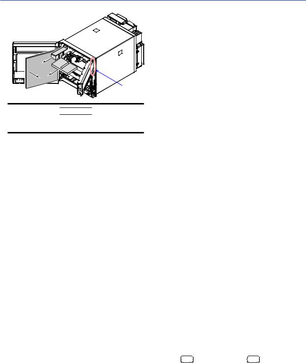
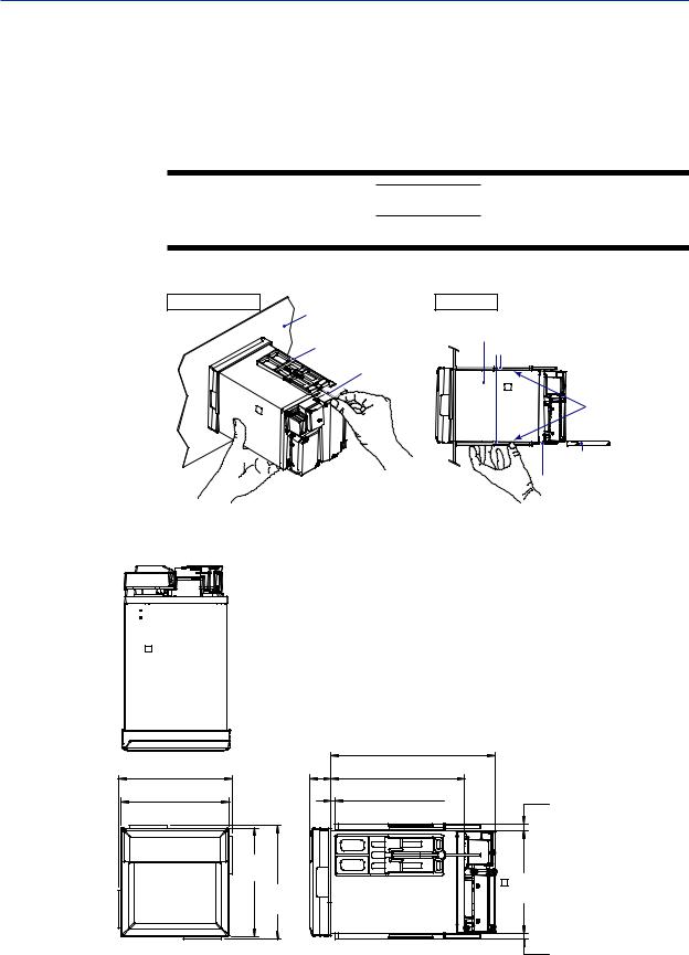
Open the door, put your finger on the tab at the lower left of the display and key panel section, and open the display and key panel section.
Tab on the display key panel section 

Open 


Open
Remove all packing materials.
• Pen Model
Hinge
IM 04P01B01-02E |
7 |
• Dot Model
Hinge
CAUTION
To protect the hinges, do not apply vertical force on the display and key panel section.
Recorder’s Version and Functions Described in This Manual
The contents of this manual corresponds to the recorder with version 1.5x.
µR10000 Versions and Functions
Version |
Suffix Code |
Added or Modified Functions |
Reference |
|
1.02 or earlier |
– |
– |
|
– |
1.1x |
– |
(Added) |
The printout/display format of the date can be changed. |
Sec. 7.19 in the User’s Manual |
|
|
|
|
(IM 04P01B01-01E) |
|
– |
(Added) |
Key operation to move the printer carriage near the center position so that the |
Sec. 3.4 in the User’s Manual |
|
|
|
ribbon cassette can be replaced with the recorder turned ON (dot model) |
(IM 04P01B01-01E) |
|
– |
(Changed) |
Selectable range of alarm values during linear scaling (including 1-5V and |
Sec. 5.2 in the User’s Manual |
|
|
|
SQRT) to -5% to 105% of the scale span. |
(IM 04P01B01-01E) |
|
– |
(Changed) |
The procedure to set the start/end date and time of Daylight Saving Time (DST) |
Sec. 6.16 in the User’s Manual |
|
|
|
has been changed. |
(IM 04P01B01-01E) |
|
/C3 |
(Added) |
Modbus/RTU slave protocol, two-wire system |
Communication manual |
|
/C7 |
(Changed) |
Users with the same user name cannot be registered. |
Communication manual |
1.2x |
-2 |
(Added) |
Language support (German and French) |
Sec. 1.9 in the User’s Manual |
|
|
|
|
(IM 04P01B01-01E) |
|
/CC1 |
(Added) |
Calibration Correction |
Sec. 1.2 in the User’s Manual |
|
|
|
|
(IM 04P01B01-01E) |
|
/H5x |
(Added) |
Portable type |
Pages 15 and 20 in this manual |
|
/P1 |
(Added) |
24 VDC/AC power supply operation |
Pages 20 and 21 in this manual |
1.3x |
– |
(Added) |
Customized menu |
Sec. 1.9 in the User’s Manual |
|
|
|
|
(IM 04P01B01-01E) |
|
– |
(Added) |
Modbus register (40301 to 40348) |
Communication manual |
|
/BT1 |
(Added) |
Header printout |
Sec. 1.4 in the User’s Manual |
|
|
|
|
(IM 04P01B01-01E) |
1.4x |
/EM1 |
(Added) |
SD memory card |
IM 04P01B01-03E |
1.5x |
– |
(Changed) |
Styel (H): 4* |
– |
|
|
|
* Style (H) 4 supports firmware version 1.5x or later. |
|
•Checking the Version Number
You can check the version number on the System display.
The System display cannot be shown at the factory default condition. First, register the System display to the display screen.
•Procedure of registering the System display to the display screen: See Changing the Displayed Information on Page 47.
•Procedure of displaying the System display: The screen switches each time the DISP
DISP key is pressed. Press the
  DISP
DISP key repeatedly until System display is shown. The displayed contents on the System display switches every 3 seconds. Check the number shown by the “Version:” item.
Software (Sold Separately)
The table below shows the relationship between the RXA10 Configuration Software revisions and the µR10000 recorder versions.
|
|
|
Recorder version |
|
|
|||
|
|
1.02 or earlier |
1.1x |
1.2x |
1.3x |
1.4x |
1.5x |
|
|
R1.01 |
Yes |
Limited |
|
|
|
|
|
RXA10 Configuration Soft- |
R2.01 |
Yes |
Yes |
Yes |
Limited |
|
|
|
R3.01 |
Yes |
Yes |
Yes |
Yes |
Limited |
|
||
ware revision |
|
|||||||
R3.05 |
Yes |
Yes |
Yes |
Yes |
Yes |
Limited |
||
|
||||||||
|
R3.06 |
Yes |
Yes |
Yes |
Yes |
Yes |
Yes |
|
|
Yes: |
Compatible |
|
Limited: |
The new functions of the recorder cannot be configured from the RXA10. |
|
|
|
8 |
IM 04P01B01-02E |
Protection of Environment
Control of Pollution Caused by the Product
This is an explanation for the product based on “Control of pollution caused by Electronic Information Products” in the People’s Republic of China.
|
|
|
|
|
|
|
|
||
|
|
|
|
|
|
|
|
|
|
|
|
|
|
|
|
|
|
|
|
|
|
|
|
|
|
|
|
|
|
|
|
|
(Pb) |
(Hg) |
|
(Cd) |
(Cr6+) |
|
|
|
|
|
|
|
|
|
|
(PBB) |
(PBDB) |
|
|
|
|
|
|
|
|
|
|
|
|
|
× |
× |
|
× |
○ |
○ |
○ |
|
|
|
× |
× |
|
× |
○ |
○ |
○ |
|
|
|
|
|
|
|
|
|
|
|
|
|
× |
× |
|
× |
○ |
○ |
○ |
|
|
|
|
|
|
|
|
|
|
|
|
|
× |
× |
|
× |
○ |
○ |
○ |
|
|
|
|
|
|
|
|
|
|
|
|
|
○ |
○ |
|
○ |
○ |
○ |
○ |
|
|
|
|
|
|
|
|
|
|
|
|
|
× |
× |
|
× |
○ |
○ |
○ |
|
|
|
|
|
|
|
|
|
|
|
|
|
× |
× |
|
× |
○ |
○ |
○ |
|
|
|
|
|
|
|
|
|
|
|
|
|
× |
× |
|
× |
○ |
○ |
○ |
|
|
|
|
|
|
|
|
|
|
( ) |
|
× |
× |
|
× |
○ |
○ |
○ |
|
|
|
|
|
|
|
|
|
|
|
|
|
|
× |
× |
|
× |
○ |
○ |
○ |
|
|
|
× |
○ |
|
○ |
○ |
○ |
○ |
|
|
|
|
|
|
|
|
|
|
/ |
6 |
|
○ |
○ |
|
○ |
○ |
○ |
○ |
|
|
|
|
|
|
|
|
|
|
|
|
|
○ |
○ |
|
○ |
○ |
○ |
○ |
|
|
|
|
|
|
|
|
|
|
|
|
|
○ |
○ |
|
○ |
○ |
○ |
○ |
|
|
|
|
|
|
|
|
|
|
|
|
|
× |
× |
|
× |
○ |
○ |
○ |
|
|
|
× |
× |
|
× |
○ |
○ |
○ |
|
|
|
|
|
|
|
|
|
|
|
|
|
× |
× |
|
× |
○ |
○ |
○ |
|
|
|
|
|
|
|
|
|
|
|
SD |
|
× |
× |
|
× |
○ |
○ |
○ |
|
|
|
|
|
|
|
|
|
|
○ GB/T26572 |
|
|
|
|
|||||
× GB/T26572 |
|
|
|
||||||
|
|
|
|
|
|||||
RoHS |
|
|
|
|
|||||
Some parts of this product include the restricted substances of RoHS Directive, but their applications are under the exemption of the directive. |
|
||||||||
|
|
|
|
|
|
|
|
|
|
SJ/T11364 ( )
) “ ”
Waste Electrical and Electronic Equipment (WEEE), Directive
This is an explanation of how to dispose of this product based on Waste Electrical and Electronic Equipment (WEEE), Directive. This directive is only valid
in the EU. • Marking
This product complies with the WEEE Directive marking requirement. This marking indicates that you must not discard this electrical/electronic product in domestic household waste.
•Product Category
With reference to the equipment types in the WEEE directive, this product is classified as a “Small equipment” product. Do not dispose in domestic household waste.
When disposing products in the EU, contact your local Yokogawa Europe B.V. office.
How to Dispose the Batteries
This is an explanation about the new EU Battery Directive (DIRECTIVE 2006/66/EC). This directive is only valid in the EU.
Batteries are included in this product. Batteries incorporated into this product cannot be removed by yourself. Dispose them together with this product.
When you dispose this product in the EU, contact your local Yokogawa Europe B.V.office. Do not dispose them as domestic household waste. Battery type: Lithium battery
Notice: The symbol (see above) means they shall be sorted out and collected as ordained in ANNEX II in DIRECTIVE 2006/66/EC.
IM 04P01B01-02E |
9 |
Function Introduction/Names of Parts
Function Introduction
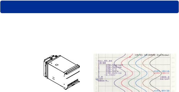
The µR10000 Recorder (hereafter referred to as the recorder) can be used to assign DC voltage, 1-5V, thermocouple, RTD, and contact or voltage ON/OFF signal to channels for measurement. The measured results are recorded with pens or dots on a chart paper that is fed at a constant speed. The pen model can record up to 4 channels; the dot model can record up to 6 channels.
µR10000 Recorder |
Recording example (dot model) |
|||||||||
|
|
|
|
|
|
|
|
|
|
|
|
|
|
|
|
|
|
|
|
|
|
|
|
|
|
|
|
|
|
|
|
|
|
|
|
|
|
|
|
|
|
|
|
|
|
|
|
|
|
|
|
|
|
|
|
|
|
|
|
|
|
|
|
|
|
|
|
|
|
|
|
|
|
|
|
|
|
|
|
|
|
|
|
|
|
|
|
Alarms
For each channel, various alarms such as high limit alarm and low limit alarm can be assigned to monitor the measured values. Alarm output relays can be used to output contact signals when alarms occur (/A1, /A2, and /A3 options).
Recording
The measured results are recorded with pens or dots on a chart paper (trend recording). The chart speed can be selected from 5 to 12000 mm/h on the pen model and 1 to 1500 mm/h on the dot model.
In addition to trend recording, various types of information can be printed on the chart paper such as numeric measured values, alarm occurrence/release, and predefined messages.
Also, the recorder settings can be printed.
Internal Light
A light is provided for easier viewing of the recording area of the chart paper.
Display
Measured values can be displayed numerically or using bar graphs on the large display. Also, alarm status and chart speed can be displayed.
Communication Functions
Using the Ethernet communication interface (/C7 option) or the RS-422A/485 communication interface (/C3 option), the measured values on the recorder can be output to a computer or a computer can be used to control the recorder.
For information about the communication functions, see the μR10000/μR20000
Communication Interface User’s Manual, IM 04P01B01-17E.
Other Main Functions
The computation function (/M1 option) can be used to perform various computations from four arithmetic operations to statistical calculations on 8 and 12 computation channels on the pen model and dot model, respectively. The computed results can be recorded.
The remote control function (/R1 option) can be used to control the recording start/ stop and other operations of the recorder by applying contact signals to the dedicated terminals.
The FAIL/chart end detection and output function (/F1 option) can be used to output contact signals when errors are detected on the recorder or when the chart paper runs out.
10 |
IM 04P01B01-02E |
Function Introduction/Names of Parts
Names of Parts
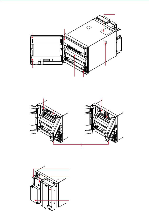
Front
|
Name plate |
|
The model name is written |
Display and key panel |
on the name plate. |
Hold the tab at the lower |
|
left and pull to open. |
|
Door |
|
|
Tag plate |
|
Mounting hole |
|
There is one hole on each of the |
|
Used to write |
Chart cassette |
top, bottom, left, and right panels. |
channel names. |
The hole is covered with a seal. |
|
|
Holds the chart paper. |
Power switch |
|
|
Turns ON/OFF the power each |
|
|
time the switch is pressed. |
Pen model |
Dot model |
|
Recording pen |
Ink ribbon |
|
Records the measured value. |
Six-color ink. |
|
Plotter pen |
Printer carriage |
|
Records measured values and |
||
Prints various types |
||
prints various types of information. |
||
of information. |
||
|
Display and key panel (see the next page) There is an internal light on the bottom section of the display and key panel. It lights up the recording area of the chart paper.
Rear Panel
Heatsink
Dissipates the internal heat.
Power terminal block
The power terminal and protective ground terminal.
Optional terminal block

 This is where terminals or ports used by options such
  as alarm output relays and communication interface are installed.
Measuring input terminal block
Measuring input terminals.


 Ethernet port (/C7 option)
The portable type (/H5x option) comes with a handle, feet, and dedicated power supply connector.
IM 04P01B01-02E |
11 |

Function Introduction/Names of Parts
Display and Key Panel
Status display
Displays the following information.
RECORD |
Illuminates while recording measured values. |
KEY LOCK |
Illuminates when key lock is enabled. |
MATH |
Illuminates when computation on the computation function (/M1 option) |
|
is in progress. |
CHART END |
Illuminates when the chart paper is out (/F1 option). |
ALARM 1 to 6 Illuminates when an alarm is occurring on channels 1 to 6.
Main display
Displays the measured values. Also, displays the setup screen when setting functions.
RECORD |
KEY LOCK |
MATH |
CHART END |
ALARM |
1 2 3 4 5 6 |
|
CHARACTER |
|
|
ESC/? |
SHIFT |
RCD |
MENU |
DISP |
FUNC |
1 MENU |
FEED CH UP |
Seven keys are available.
For all keys except RCD, functions marked above the keys are enabled when setting functions or when the FUNC key or the DISP MENU key is pressed.
<While setting functions, when the FUNC key/DISP MENU key is pressed>
CHARACTER Key: Changes the character type when entering a character. Press this key while holding down the SHIFT key to switch the character type in reverse order.
UP/DOWN Key: Switches the setup item or the value.
Press this key while holding down the SHIFT key to switch the setup item or the value in reverse order.
LEFT/RIGHT Key: Moves the cursor to the right when entering a value or character. Press this key while holding down the SHIFT key to move the cursor to the left.
|
ESC Key: Cancels the operation. |
|
|
|
|
When pressed with the SHIFT key, the display of the comment |
|||
|
on the setting turns ON/OFF. |
|
|
|
|
|
SHIFT Key: Used with the |
key, |
key, |
|
|
the CHARACTER key, or the ESC key. |
|
|
|
|
ENTER Key: Confirms the setup item or value. |
||
CHARACTER |
ESC/? |
SHIFT |
|
|
RCD MENU |
DISP FUNC 1 MENU |
FEED CH UP |
<During normal operation> |
|
|
|
|
||
|
|
CH UP key |
|
|
|
|
Switches the displayed channel. |
||
|
|
(when manual switching is specified) |
||
|
|
FEED key |
|
|
|
|
Feeds the chart paper. |
|
|
|
DISP MENU key |
|
|
|
|
Hold this key down for 3 seconds to switch to the data display |
|||
|
setup screen. Hold this key down for 3 seconds also to exit |
|||
|
from the data display setup screen. |
|
|
|
|
FUNC key |
|
|
|
|
Used when executing manual printout, message printout, etc. |
|||
|
DISP key |
|
|
|
|
Switches the screen in the main display. |
|
|
|
MENU key
Hold this key down for 3 seconds to enter Setting mode. Hold this key down for 3 seconds also to exit from Setting mode.
RCD key
Starts/stops recording.
12 |
IM 04P01B01-02E |

Installing/Wiring the Recorder
Installation Location
Install the recorder indoors in a location that meets the following conditions.
•Instrument Panel
The recorder is designed for panel mounting. The portable type (/H5x option) is designed to be used on the desktop.
•Well-Ventilated Location
To prevent overheating, install the recorder in a well-ventilated location.
For the panel cut dimensions when arranging multiple recorders, see page 15. Follow the panel cut dimensions providing adequate space between instruments when other instruments are arranged on the panel.
We recommend that you secure at least 50 mm of space from the left, right, top, and rear panels on the portable type (/H5x option).
•Minimum Mechanical Vibrations
Choose an installation location with the minimum mechanical vibration.
Installing the recorder in a location with large mechanical vibration not only causes adverse effects on the mechanism but also may hinder normal recording.
•Horizontal
Install the recorder horizontally (However, the recorder can be inclined up to 30 degrees backwards for panel mounting).
•Ambient temperature range between 0 to 50°C
•Ambient humidity between 20 to 80%RH (at 5 to 40°C) or 30 to 50%RH (at 0 to 5, 40 to 50°C), No condensation should be present.
•Altitude 2000 m or less
Note
•Condensation may occur if the recorder is moved to another place where both the ambient temperature and humidity are higher, or if the temperature changes rapidly. In addition, measurement errors will result when using thermocouples. In this case, let the recorder adjust to the new environment for at least one hour before using it.
•The chart paper may be adversely affected by a rapid change in the ambient temperature and humidity.
Do not install the recorder in the following places.
•Outdoors
•In Direct Sunlight or Near Heat Sources
Install the recorder in a place with small temperature fluctuations near room temperature (23°C). Placing the recorder in direct sunlight or near heat appliances can cause adverse effects on the internal circuitry.
•Where an Excessive Amount of Soot, Steam, Moisture, Dust, or Corrosive Gases Are Present
Soot, steam, moisture, dust, and corrosive gases will adversely affect the recorder.
Avoid such locations.
•Near Strong Magnetic Field Sources
Do not bring magnets or instruments that produce electromagnetic fields close to the recorder. Strong magnetic fields can cause errors in the measurements.
Installation Procedure
The recorder should be mounted on a steel panel of thickness 2 mm to 26 mm.
1.Insert the recorder from the front of the panel (see the diagram on the next page).
2.Mount the recorder to the panel using the mounting brackets provided.
•Use two brackets to support the top and bottom or the left andright sides of the case
(remove the seal that is covering the holes for the mounting brackets beforehand).
IM 04P01B01-02E |
13 |
Installing/Wiring the Recorder
•The proper torque for tightening the mounting screws is 0.7 to 0.9 N•m.
•Mount the recorder to the panel according to the procedure below.
•First, attach the two mounting brackets and temporarily fasten the attachment screws.
•Next, fix the recorder in place by tightening the attachment screws with the appropriate torque. When the recorder is approximately perpendicular to the panel as you fasten the screws, press the mounting bracket against the case so that they are in contact with each other.
CAUTION
Tightening the screws too much can deform the case or damage the bracket.
Panel Mounting Diagram
Screw temporarily |
Panel |
Fix in place |
|
|
|
|
|
|
Mounting bracket |
Panel |
Case |
|
|
Mounting bracket |
|
|
Attachment |
|
|
|
|
|
|
|
screw |
|
|
|
Front |
|
In contact |
|
|
with each other |
|
|
|
|
|
|
|
|
Torque driver |
|
|
|
(flat blade) |
|
|
|
Attachment screw |
(The figure shows the case when the mounting |
|||
brackets are used on the top and bottom of the case.) |
|||
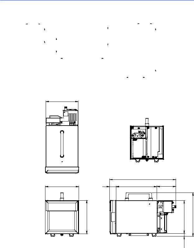
External Dimensions
Unit: mm (approx. inch)
Unless otherwise specified, tolerance is ± 3% (however, tolerance is ± 0.3 mm when below 10 mm).
|
|
220 (8.66) |
|
|
151.5 (5.96) |
(1.08) 27.5 |
178 (7.01) |
|
|
144 (5.67) |
|
Mounting panel 2 to 26 |
9.4 |
(Dimensions before attaching |
|
|
thickness |
(0.37)the mounting bracket) |
|
|
|
|
||
|
144 |
|
|
|
|
(5.67) |
|
136.5 |
|
|
151.5 |
|
|
|
|
|
(5.37) |
|
|
|
(5.96) |
|
|
|
|
|
|
7.5 |
(Dimensions after attaching |
|
|
|
(0.30) the mounting bracket) |
|
14 |
IM 04P01B01-02E |
Installing/Wiring the Recorder
Panel Cutout
Single-Unit Mounting |
Side-by-Side Mounting |
Side-by-Side Mounting |
|
|
|
||||||||||||||||||||||||||||||
|
|
|
|
|
|
|
+2 |
|
|
|
|
|
|
|
(horizontally) |
(vertically, max. 3 units) |
|
|
|
||||||||||||||||
137 |
|
|
|
|
|
|
|
|
|
|
|
|
|
|
|
|
|
|
|
137 |
+2 |
|
|
|
|
|
|
||||||||
0 |
|
|
|
|
|
|
|
|
|
|
|
|
|
|
|
|
0 |
|
|
|
|
|
|
||||||||||||
|
|
|
|
|
|
|
|
|
|
|
|
|
|
|
|
|
|
(5.39) |
|
|
|
|
|
|
|||||||||||
(5.39) |
|
|
|
|
|
|
|
|
|
|
|
|
|
|
|
|
|
|
|
|
|
|
|||||||||||||
|
|
|
|
|
|
|
|
|
|
|
|
|
|
|
|
|
|
|
|
|
|
|
|
|
|
|
|
|
|
|
|
|
|
|
|
|
|
|
|
|
|
|
|
|
|
|
|
|
|
|
|
|
|
|
|
|
|
|
|
|
|
|
|
|
|
|
|
|
|
Units |
L (mm) |
|
|
|
|
|
|
|
|
|
137 +2 |
|
|
|
|
|
|
|
|
175 min. |
|
|
|
|
|
|
|
|
|
|
|
|
|||||
|
|
|
|
|
|
|
|
|
|
|
|
|
|
2 |
282 |
||||||||||||||||||||
|
|
|
|
|
|
|
|
|
|
|
|
|
|
|
|
|
|
|
|
|
|
|
|
||||||||||||
|
|
|
|
|
|
|
|
|
(5.39)0 |
|
|
|
|
|
|
|
(6.89) |
|
|
|
|
|
|
|
|
|
|
|
|||||||
|
|
|
|
|
|
|
|
|
|
|
137 |
|
|
|
|
|
|
|
|
|
|
|
|
|
|
|
|
|
|
|
|
|
|
3 |
426 |
|
|
|
|
|
|
|
|
|
|
|
+2 |
|
|
|
|
|
|
|
|
|
|
|
|
|
|
|
|
|
|
|
|
4 |
570 |
||
|
|
|
|
|
|
|
|
|
|
|
|
|
|
|
|
|
|
|
|
|
|
|
|
|
|
|
|
|
|
|
|||||
|
|
|
|
|
|
|
|
|
|
|
|
|
|
|
|
|
|
|
|
|
|
|
|
|
|
|
|
||||||||
|
|
|
|
|
|
|
(5.39)0 |
|
|
|
|
|
|
|
|
|
|
|
|
|
|
|
|
|
|
|
+2 |
|
|
||||||
|
|
|
|
|
|
|
|
|
|
|
|
|
|
|
|
|
|
|
|
|
|
|
L |
5 |
714 |
||||||||||
|
|
|
|
|
|
|
|
|
|
|
|
|
|
|
|
|
|
|
|
|
|
|
|
|
|
|
|
|
|
0 |
|||||
|
|
|
|
|
|
|
|
|
|
|
|
|
|
|
|
|
|
|
|
|
|
|
|
|
|
|
|
|
|
|
|
|
|
6 |
858 |
|
|
|
|
|
|
|
|
|
|
|
|
|
|
|
+2 |
|
|
|
|
|
|
|
|
|
|
|
|
|
|
||||||
|
|
|
|
|
|
|
|
|
|
|
|
|
|
|
|
L 0 |
|
|
|
|
|
|
|
|
|
|
|
|
|
|
|
|
|||
|
|
|
|
|
|
|
|
|
|
|
|
|
|
|
|
|
|
|
|
|
|
|
|
|
|
7 |
1002 |
||||||||
Attach the mounting brackets to the top and bottom when |
|
|
|
|
|
|
|
|
|
|
|
||||||||||||||||||||||||
|
|
|
|
|
|
|
|
|
|
|
8 |
1146 |
|||||||||||||||||||||||
mounting the recorders side-by-side horizontally or right and |
|
|
|
|
|
|
|
|
|
|
|
9 |
1290 |
||||||||||||||||||||||
left when mounting the recorders side-by-side vertically. |
|
|
|
|
|
|
|
|
|
|
|
||||||||||||||||||||||||
|
|
|
|
|
|
|
|
|
|
|
10 |
1434 |
|||||||||||||||||||||||
|
|
175 min. |
|
|
|
|
|
|
|||||||||||||||||||||||||||
Unit: mm (approx. inch) |
|
|
|
|
|
|
|
|
|
|
|
|
|
|
|
|
|||||||||||||||||||
|
|
|
|
|
|
|
|
|
|
|
|
|
|
|
|
||||||||||||||||||||
|
|
|
|
|
|
|
|
|
|
|
|
|
|
|
|
n |
(144xn)-6 |
||||||||||||||||||
Unless otherwise specified, tolerance is ± 3% |
(6.89) |
|
|
|
|
|
|
||||||||||||||||||||||||||||
|
|
|
|
|
|
|
|
||||||||||||||||||||||||||||
(however, tolerance is ± 0.3 mm when below 10 mm).
External Dimensions of the Portable Type (/H5x Option)
138.5 (5.45) |
40VAMAX |
50/60Hz |
100-240V~ |
Unit: mm (approx. inch)
Unless otherwise specified, tolerance is ± 3% (however, tolerance is ± 0.3 mm when below 10 mm).
|
|
285 (11.2) |
|
|
144 (5.67) |
27.5 |
176 (6.93) |
81.5 (3.21) |
|
|
(1.08) |
|
|
|
|
<![if ! IE]> <![endif]>144 (5.67) |
|
<![if ! IE]> <![endif]>141.5 (5.57) |
<![if ! IE]> <![endif]>187 (7.36) |
|
|
|
<![if ! IE]> <![endif]>12.4 (0.49) |
|
IM 04P01B01-02E |
15 |
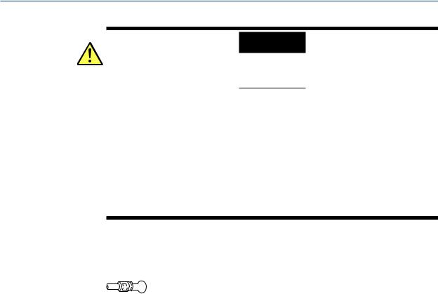
Installing/Wiring the Recorder
Input Signal Wiring
WARNING
• To prevent electric shock while wiring, ensure that the power supply source is turned OFF.
CAUTION
•The input terminals of this instrument are specific to this instrument. Do not connect the input terminals of the µR1000, µR1800 or other models, as malfunction may result.
•If a strong tension is applied to the cable wired to the recorder, the terminals of the recorder and/or the cable can be damaged. In order to prevent tension from being applied directly on the terminals, fasten all wiring cables to the rear of the mounting panel.
•Do not apply a voltage exceeding the following value to the input terminals as this may damage the recorder.
•Maximum input voltage
Voltage range less than or equal to 200 mVDC, TC, RTD, and DI: ±10 VDC Ranges other than those listed above: ±60 VDC
•Maximum common-mode voltage
±60 VDC (under measurement category II conditions)
Precautions to Be Taken While Wiring
Take the following precautions when wring the input signal cables.
It is recommended that crimp-on lug with insulation sleeves (designed for 4-mm screws) be used when connecting the input/output signal wires to the terminals. However, this does not apply clamped terminals (/H2).

 Crimp-on lug with insulation sleeves (for 4-mm screws)
For clamped terminals (/H2), the following wire is recommended.
•Conductive cross-sectional area for single wire: 0.14 mm2 to 1.5 mm2, stranded wire: 0.14 mm2 to 1.0 mm2
•Length of the stripped section of the wire: Approx. 5 mm
Take measures to prevent noise from entering the measurement circuit.
•Move the measurement circuit away from the power cable (power ircuit) and ground circuit.
•It is desirable that the object being measured does not generate noise. However, if this is unavoidable, isolate the measurement circuit from the object. Also, ground the object being measured.
•Shielded wires should be used to minimize noise caused by electrostatic induction.
Connect the shield to the ground terminal of the recorder as necessary (make sure you are not grounding at two points).
•To minimize noise caused by electromagnetic induction, twist the measurement circuit wires at short, equal intervals.
•Make sure to earth ground the protective ground terminal through minimum resistance.
Do not allow static electricity to be applied to the terminals.
•When wiring the terminals, remove static electricity so that static electricity is not applied.
•If static electricity or similar high-voltage transient noise is applied to the signal line, the system may break.
When using internal reference junction compensation on the thermocouple input, take measures to stabilize the temperature at the input terminal.
• Always use the terminal cover.
• Do not use thick wires which may cause large heat dissipation (cross sectional area of
0.5 mm2 or less recommended).
• Make sure that the ambient temperature remains reasonably stable. Large temperature fluctuations can occur if a nearby fan turns ON or OFF.
Connecting the input wires in parallel with other devices can cause signal
degradation, affecting all connected devices.
If you need to make a parallel connection, then
•Turn the burnout detection function OFF.
•Ground the instruments to the same point.
•Do not turn ON or OFF another instrument during operation. This can have adverse effects on the other instruments.
•RTDs cannot be wired in parallel.
16 |
IM 04P01B01-02E |
Loading...