


 Loading...
User’s |
|
|
|
|
|
|
|
|
|
|
Manual |
Model DC402G [Style: S2] |
|
|
|
|
|||||
|
|
|
|
|||||||
|
Converter for Dual Cell |
|
|
|
|
|||||
|
Conductivity and Resistivity |
|
|
|
|
|||||
|
|
|
||||||||
|
|
|
|
IM 12D08E02-01E |
||||||
|
|
|
|
|
|
|
|
|
|
|
|
|
|
|
|
|
|
|
|
|
|
|
|
|
|
|
|
|
|
|
|
|
|
|
|
|
|
|
|
|
|
|
|
|
|
|
|
|
|
|
|
|
|
|
IM 12D08E02-01E
4th Edition

PREFACE
WARNING
Electric discharge
The EXA analyzer contains devices that can be damaged by electrostatic discharge. When servicing this equipment, please observe proper procedures to prevent such damage. Replacement components should be shipped in conductive packaging. Repair work should be done at grounded workstations using grounded soldering irons and wrist straps to avoid electrostatic discharge.
Installation and wiring
The EXA analyzer should only be used with equipment that meets the relevant IEC, American or Canadian standards. Yokogawa accepts no responsibility for the misuse of this unit.
 CAUTION
The Instrument is packed carefully with shock absorbing materials, nevertheless, the instrument may be damaged or broken if subjected to strong shock, such as if the instrument is dropped. Handle with care.
Although the instrument has a weatherproof construction, the transmitter can be harmed if it becomes submerged in water or becomes excessively wet.
Do not use an abrasive or solvent in cleaning the instrument.
Notice
•This manual should be passed on to the end user.
•The contents of this manual are subject to change without prior notice.
•The contents of this manual shall not be reproduced or copied, in part or in whole, without permission.
•This manual explains the functions contained in this product, but does not warrant that they are suitable the particular purpose of the user.
•Every effort has been made to ensure accuracy in the preparation of this manual.
However, when you realize mistaken expressions or omissions, please contact the nearest Yokogawa Electric representative or sales office.
•This manual does not cover the special specifications. This manual may be left unchanged on any change of specification, construction or parts when the change does not affect the functions or performance of the product.
•If the product is not used in a manner specified in this manual, the safety of this product may be impaired.
Yokogawa is not responsible for damage to the instrument, poor performance of the instrument or losses resulting from such, if the problems are caused by:
•Improper operation by the user.
•Use of the instrument in improper applications
•Use of the instrument in an improper environment or improper utility program
•Repair or modification of the related instrument by an engineer not authorized by Yokogawa.
Safety and Modification Precautions
•Follow the safety precautions in this manual when using the product to ensure protection and safety of the human body, the product and the system containing the product.
The following safety symbols are used on the product as well as in this manual.
 DANGER
This symbol indicates that an operator must follow the instructions laid out in this manual in order to avoid the risks, for the human body, of injury, electric shock, or fatalities. The manual describes what special care the operator must take to avoid such risks.
IM 12D08E02-01E
4th Edition: Feb. 2014(YK)
All Rights Reserved, Copyright © 2007, Yokogawa Electric Corporation
IM 12D08E02-01E

 WARNING
This symbol indicates that the operator must refer to the instructions in this manual in order to prevent the instrument (hardware) or software from being damaged, or a system failure from occurring.
 CAUTION
This symbol gives information essential for understanding the operations and functions.
This symbol indicates Protective Ground Terminal
This symbol indicates Function Ground Terminal (Do not use this terminal as the protective ground terminal.)
This symbol indicates Alternating current.
This symbol indicates Direct current.
Warranty and service
Yokogawa products and parts are guaranteed free from defects in workmanship and material under normal use and service for a period of (typically) 12 months from the date of shipment from the manufacturer. Individual sales organizations can deviate from the typical warranty period, and the conditions of sale relating to the original purchase order should be consulted. Damage caused by wear and tear, inadequate maintenance, corrosion, or by the effects of chemical processes are excluded from this warranty coverage.
In the event of warranty claim, the defective goods should be sent (freight paid) to the service department of the relevant sales organization for repair or replacement (at Yokogawa discretion). The following information must be included in the letter accompanying the returned goods:
•Part number, model code and serial number
•Original purchase order and date
•Length of time in service and a description of the process
•Description of the fault, and the circumstances of failure
•Process/environmental conditions that may be related to the installation failure of the device
•A statement whether warranty or non-warranty service is requested
•Complete shipping and billing instructions for return of material, plus the name and phone number of a contact person who can be reached for further information.
Returned goods that have been in contact with process fluids must be decontaminated/disinfected before shipment. Goods should carry a certificate to this effect, for the health and safety of our employees. Material safety data sheets should also be included for all components of the processes to which the equipment has been exposed.
How to dispose the batteries:
This is an explanation about the new EU Battery Directive (DIRECTIVE 2006/66/EC). This directive is only valid in the EU. Batteries are included in this product. Batteries incorporated into this product cannot be removed by yourself. Dispose them together with this product. When you dispose this product in the
EU, contact your local Yokogawa Europe B.V.office. Do not dispose them as domestic household waste. Battery type: silver oxide battery
Notice:
The symbol (see above) means they shall be sorted out
and collected as ordained in ANNEX II in DIRECTIVE 2006/66/EC.
IM 12D08E02-01E
TABLE OF CONTENTS |
|
PREFACE..................................................................................................................... |
1 |
1. Introduction And General Description.............................................................. |
1-1 |
1-1. Instrument Check............................................................................................ |
1-1 |
1-2. Application....................................................................................................... |
1-2 |
2. DC402G Specifications....................................................................................... |
2-1 |
2-1. General specifications..................................................................................... |
2-1 |
2-2. Operating specifications.................................................................................. |
2-2 |
2-3. Model and suffix codes.................................................................................... |
2-3 |
3. Installation And Wiring....................................................................................... |
3-1 |
3-1. Installation and dimensions............................................................................. |
3-1 |
3-1-1. Installation site.................................................................................................................. |
3-1 |
3-1-2. Mounting methods............................................................................................................ |
3-1 |
3-2. Preparation...................................................................................................... |
3-4 |
3-3. Wiring the power supply.................................................................................. |
3-5 |
3-3-1. General precautions......................................................................................................... |
3-5 |
3-3-2. Access to terminal and cable entry.................................................................................. |
3-5 |
3-3-3. AC power.......................................................................................................................... |
3-6 |
3-3-4. Grounding the housing..................................................................................................... |
3-6 |
3-3-5. Switching on the instrument............................................................................................. |
3-6 |
3-4. Wiring the contact signals............................................................................... |
3-7 |
3-4-1. General precautions......................................................................................................... |
3-7 |
3-4-2. Contact outputs................................................................................................................ |
3-7 |
3-4-3. Contact input.................................................................................................................... |
3-7 |
3-5. Wiring the analog output signals..................................................................... |
3-7 |
3-5-1. General precautions......................................................................................................... |
3-7 |
3-5-2. Analog output signals....................................................................................................... |
3-7 |
3-6. Sensor wiring................................................................................................... |
3-8 |
3-7. Sensor connection using junction box and extension cable............................ |
3-8 |
3-8. Other sensor systems..................................................................................... |
3-9 |
4. Operation; Display Functions And Setting....................................................... |
4-1 |
4-1. Operator interface........................................................................................... |
4-1 |
4-2. Explanation of operating keys......................................................................... |
4-2 |
4-3. Setting passcodes........................................................................................... |
4-3 |
4-4. Display example.............................................................................................. |
4-3 |
4-5. Display functions............................................................................................. |
4-4 |
5. Parameter setting................................................................................................ |
5-1 |
5-1. Maintenance mode.......................................................................................... |
5-1 |
5-1-1. Introduction....................................................................................................................... |
5-1 |
5-1-2. Manual activation of Hold................................................................................................. |
5-2 |
5-1-3. Setpoint adjustment.......................................................................................................... |
5-3 |
5-2. Commissioning mode...................................................................................... |
5-4 |
5-2-1. Introduction....................................................................................................................... |
5-4 |
5-2-2. Setpoints.......................................................................................................................... |
5-5 |
5-2-3. Range............................................................................................................................... |
5-7 |
5-2-4. Hold.................................................................................................................................. |
5-9 |
5-2-5. Temperature compensation........................................................................................... |
5-11 |
5-2-6. Service........................................................................................................................... |
5-13 |
5-3. Notes for guidance in the use of service coded settings............................... |
5-14 |
5-3-1. Parameter specific functions.......................................................................................... |
5-14 |
5-3-2. Temperature measuring functions................................................................................. |
5-14 |
IM 12D08E02-01E
5-3-3. Temperature compensation functions............................................................................ |
|
5-16 |
5-3-4. mA output functions....................................................................................................... |
|
5-18 |
5-3-5. Contact outputs.............................................................................................................. |
|
5-20 |
5-3-6. User interface................................................................................................................. |
|
5-24 |
5-3-7. Communication setup..................................................................................................... |
|
5-26 |
5-3-8. General .......................................................................................................................... |
|
5-26 |
5-3-9. Test and setup mode .................................................................................................... |
|
5-26 |
6. Calibration........................................................................................................... |
|
6-1 |
6-1 When is calibration necessary?........................................................................ |
|
6-1 |
6-2. Calibration procedure...................................................................................... |
|
6-2 |
6-3. Calibration with HOLD active.......................................................................... |
|
6-3 |
7. Maintenance........................................................................................................ |
|
7-1 |
7-1. Periodic maintenance for the EXA 402 converter............................................ |
|
7-1 |
7-2. Periodic maintenance of the sensor................................................................ |
|
7-1 |
7-3. Fuse Replacement.......................................................................................... |
|
7-2 |
8. Troubleshooting.................................................................................................. |
|
8-1 |
8-1. Diagnostics...................................................................................................... |
|
8-1 |
8-1-1. Off-line checks.................................................................................................................. |
|
8-1 |
8-1-2. On-line checks.................................................................................................................. |
|
8-1 |
9. Spare Parts.......................................................................................................... |
|
9-1 |
10. Appendix ......................................................................................................... |
|
10-1 |
10-1. User setting for non-linear output table (code 31, 35 and 36)..................... |
10-1 |
|
10-2. User entered matrix data (code 23 to 28).................................................... |
|
10-1 |
10-3. Matrix data table (user selectable in code 22)............................................. |
|
10-2 |
10-4. Sensor Selection......................................................................................... |
|
10-3 |
10-4-1. General......................................................................................................................... |
|
10-3 |
10-4-2. Sensor selection........................................................................................................... |
|
10-3 |
10-4-3. Selecting a temperature sensor................................................................................... |
|
10-3 |
10-5. Setup for other functions............................................................................. |
|
10-3 |
10-6. User setting table........................................................................................ |
|
10-4 |
10-7. Configuration checklist for DC402G ........................................................... |
|
10-6 |
10-8. USP <645> Water Purity Monitoring........................................................... |
|
10-7 |
10-9. WHAT IS DUAL CONDUCTIVITY?............................................................. |
|
10-9 |
11. Appendix 2 QUALITY INSPECTION................................................................ |
|
11-1 |
Customer Maintenance Parts List (for Style: S2)................... |
CMPL 12D08E02-02E |
|
Revision Record........................................................................................................... |
|
i |
IM 12D08E02-01E
Introduction 1-1
1. Introduction And General Description
The Yokogawa EXA 402 is a 4-wire converter designed for industrial process monitoring, measurement and control applications. This instruction manual contains the information needed to install, set up, operate and maintain the unit correctly. This manual also includes a basic troubleshooting guide to answer typical user questions.
Yokogawa can not be responsible for the performance of the EXA analyzer if these instructions are not followed.
1-1. Instrument Check
Upon delivery, unpack the instrument carefully and inspect it to ensure that it was not damaged during shipment. If damage is found, retain the original packing materials (including the outer box) and then immediately notify the carrier and the relevant Yokogawa sales office.
Make sure the model number on the nameplate affixed to the top of the display board of the instrument agrees with your order.
 WARNING
The nameplate will also contain the serial number and power supply selection.
Be sure to apply correct power to the unit.
MODEL |
DC402G |
SUPPLY |
115VAC 50/60Hz MAX.10VA |
SUFFIX |
|
OUTPUT 0-20mADC or 4-20mADC |
|
STYLE |
|
No. |
|
|
Made in Japan |
|
|
Figure 1-1. Nameplate
Check that all the parts are present, including mounting hardware, as specified in the option codes at the end of the model number. For a description of the model codes, refer to Chapter 2 of this manual under
General Specifications.
Basic Parts List:Converter EXA 402
Instruction Manual English
Optional mounting hardware when specified (See model code)
IM 12D08E02-01E
1-2 Introduction
1-2. Application
The EXA converter is intended to be used for continuous on-line measurement in industrial installations. The unit combines simple operation and microprocessor-based performance with advanced self-diag- nostics and enhanced communications capability to meet the most advanced requirements. The measurement can be used as part of an automated process control system. It can also be used to indicate dangerous limits of a process, to monitor product quality, or to function as a simple controller for a dosing/neutralization system.
Yokogawa designed the EXA analyzer to withstand harsh environments. The converter may be installed either indoors or outside because the IP65 (NEMA 4X) housing and cabling glands ensure the unit is adequately protected. The flexible polycarbonate window on the front door of the EXA allows pushbutton access to the keypad, thus preserving the water and dust protection of the unit even during routine maintenance operations.
A variety of EXA hardware is optionally available to allow wall, pipe, or panel mounting. Selecting a proper installation site will permit ease of operation. Sensors should normally be mounted closely to the converter in order to ensure easy calibration and peak performance. If the unit must be mounted remotely from the sensors, WF10 extension cable can be used up to a maximum of 50 metres (150 feet) with a BA10 junction box.
The EXA is delivered with a general purpose default setting for programmable items. (Default settings are listed in Chapter 5 and again in Chapter 10). While this initial configuration allows easy start-up, the configuration should be adjusted to suit each particular application. An example of an adjustable item is the type of temperature sensor used. The EXA can be adjusted for any one of five different types of temperature sensors.
To record such configuration adjustments, write changes in the space provided in Chapter 10 of this manual. Because the EXA is suitable for use as a monitor, a controller or an alarm instrument, program configuration possibilities are numerous.
Details provided in this instruction manual are sufficient to operate the EXA with all Yokogawa sensor systems and a wide range of third-party commercially available probes. For best results, read this manual in conjunction with the corresponding sensor instruction manual.
IM 12D08E02-01E

Specification 2-1
2. DC402G Specifications
2-1. General specifications |
% Deviation (100x[ (cell2-cell1)/cell1] ) |
||
A. Input specifications |
|||
- Min. span : 0.1 |
|||
|
:Two inputs , each 2-electrode |
- Max. span: 400 |
|
|
measurement with square wave |
|
|
|
excitation, using cell constants(C) |
VGB-directive 450 L |
|
|
from 0.008 to 50.0 cm-1, with up |
- Min. span : 1.0 pH |
|
|
to 60 metres (200ft) connection |
- Max. span : 14.0 pH |
|
|
cable. |
Temperature |
|
B. Detection method |
|||
- Min. span : 25 °C (50 °F) |
|||
|
:Frequency, read-pulse position |
- Max. span : 250°C (500 °F) |
|
|
and reference voltage are |
|
|
|
dynamically optimized. |
Difference Temperature |
|
C. Input ranges |
- Min. span : 25 °C (50 °F) |
||
- Max. span: 250 °C (500 °F) |
|||
Minimum :1µS x C at process temperature |
|
||
|
(underrange 0.000 µS/cm). |
E. Transmission Signals |
|
Maximum:25 mS x C at process temperature |
: Two isolated outputs of 0/4-20 |
||
|
(overrange 30 mS x C). |
mA DC with common negative. |
|
-Resistivity:0.00 kΩ - 999 MΩ/C at 25 °C |
Max. load : 600 Ω. |
||
|
(77 °F) reference temperature. |
Auxiliary output can be chosen |
|
Minimum :40 Ω/C at process temperature |
from conductivity, linearized |
||
|
(underrange 0.001 kΩ x cm). |
conductivity, resistivity, |
|
Maximum:1 MΩ/C at process temperature |
temperature, differential |
||
|
(overrange 999 MΩ x cm). |
temperature calculated value |
|
-Temperature |
or PI control of conductivity/ |
||
Pt1000 |
: -20 to +250 °C (0 to 500 °F) |
resistivity. |
|
Pt100 and Ni100 |
Burn up (22 mA) or Burn down |
||
|
: -20 to +200 °C (0 to 400 °F) |
(0/3.5 mA) to signal failure. |
|
8K55 NTC |
: -10 to +120 °C (10 to 250 °F) |
|
|
PB36 NTC |
: -20 to +120 °C (0 to 250 °F) |
F. Temperature compensation |
|
D. Span |
|
: Automatic, for temperature |
|
|
ranges mentioned under C |
||
Conductivity/Resistivity |
(input ranges). |
||
- Min. span |
: 0.010 µS/cm; 0.001 kΩ x cm |
- Reference temperature |
|
|
up to 90% maximum zero |
: programmable from 0 to 100 °C |
|
|
suppression. |
or 30 to 210 °F (default 25 °C). |
|
- Max. span : 1500 mS/cm; 999 MΩ x cm |
G. Compensation algorithm |
||
Ratio (cell1/cell2) |
|||
: According IEC 60746-3 |
|||
- Min. span |
: 00.0 |
NaCl tables (default). Two |
|
- Max. span : 19.99 |
independent user programmable |
||
Difference (cell1cell2) |
temperature coefficients, from |
||
0% to 3.5% per °C (°F) by |
|||
- Min. span |
: 0.010 µS/cm |
adjustment or calibration. |
|
- Max. span : 400 mS/cm |
- Matrix compensation |
||
% Passage (100x[cell2/cell1] ) |
: with conductivity function |
||
of concen-tration and |
|||
- Min. span |
: 00.0 |
temperature. Choice of 5 |
|
- Max. span : 199.9 |
preprogrammed matrixes |
||
% Rejection (100x[( cell1-cell2)/cell1] ) |
and a 25-points user- |
||
programmable matrix. |
|||
- Min. span |
: 0.1 |
|
|
- Max. span : 400
IM 12D08E02-01E
2-2 Specification |
|
H. Display |
: Custom liquid crystal display, |
|
with a main display of 31/2 |
|
digits 12.5 mm high. Message |
|
display of 6 alphanumeric |
|
characters, 7 mm high. Warn- |
|
ing flags and units (mS/cm, |
|
kΩ·cm, µS/cm and MΩ·cm) as |
|
appropriate. |
I.Contact Outputs
-General : Four (4) SPDT relay contacts with LED indicators. For S1, S2, and S3, the LED is on when relay power is removed.
NOTE: For S4 (FAIL) LED lights when relay is deenergised (Fail safe).
Contact outputs configurable for hysteresis and delay time.
-Switch capacity
:Maximum values 100 VA, 250 VAC, 5 Amps.
Maximum values 50 Watts,
250 VDC, 5 Amps.
-Status : High/low process alarms,
selected from conductivity, resistivity and temperature. Contact output is also available to signal “Hold active”
-Control function
:On/Off
PI pulsed |
: Proportional duty cycle control |
|
with integral term. |
PI frequency |
: Proportional frequency control |
|
with integral term. |
|
(PI control on Conductivity/ |
|
Resistivity only) In addition |
|
FAIL alarm for system and |
|
diagnostic errors on S4. |
J. Power Supply
Supply voltage rating: 115, 230 VAC
Applicable range: 97.8 to 132.2, 195.5 to
264.5 VAC Supply frequency rating: 50 / 60 Hz
Applicable range: 50 Hz ± 5% / 60 Hz ± 5% Power consumption: Maximum 10 VA for
steady operation
K.Shipping Details Package size
:W x H x D
290 x 300 x 290 mm.
11.5 x 11.8 x 11.5 in.
Packed weight
:approx. 2.5 kg (5lb).
2-2. Operating specifications
A. Performance : Conductivity
- Linearity : ± 0.5 % FS
-Repeatability : ± 0.5 % FS
-Accuracy : ± 0.5 FS
Performance |
: Resistivity |
- Linearity : |
± 0.5 FS |
-Repeatability : ± 0.5 % FS
-Accuracy : ± 0.5 % FS
Performance : TemperaturewithPt1000Ω,
Ni100ΩandPB36NTC
- Linearity : ± 0.3 °C
-Repeatability : ± 0.3 °C
-Accuracy : ± 0.3 °C
Performance |
: Temperature with PT100Ω |
|
and 8k55Ω |
- Linearity |
: ± 0.4 °C |
- Repeatability: ± 0.4 °C |
|
- Accuracy |
: ± 0.4 °C |
Note; The following tolerance are added to |
|
above performance. |
|
mA output tolerance : ± 0.02 mA of |
|
|
"0/4 - 20 mA" |
Digital display tolerance: +1 digit |
|
Performance : Temperature compensation
- NaCl table : ± 1 % - Matrix : ± 3 %
- Step response: 90 % (< 2 decades) in ≤ 6 seconds
B.Ambient operating temperature
:-10 to +55 °C (14 to 131 ºF)
C.Storage temperature
:-30 to +70 °C (-20 to 160 ºF)
D.Humidity
:10 to 90% RH non-condensing
IM 12D08E02-01E

E. Housing
:Cast aluminium case with chemically resistant
coating, cover with flexible polycarbonate window. Case color is off-white and cover is moss green. Cable entry is via six PG13.5 nylon glands. Cable terminals are provided for up to 2.5 mm finished wires. Weather resistant to IP65. Pipe wall or panel mounting, using optional hardware.
F.Data protection
:EEPROM for configuration and logbook, and lithium battery for clock.
G.Watchdog timer
:Checks microprocessor
H.Automatic safeguard
:Return to measuring mode when no keystroke is made for 10 min.
I.Power interruption
:Less than 50 milliseconds no effect.
J.Operation protection
:3-digit programmable password.
K.Safety and EMC conforming standards
Safety |
|
|
|
|
|
|
, |
|
|
|
|
|
|
||
|
|
|
|
||||
: conforms to EN 61010-1, |
|||||||
EMC |
: EN 61326-1 Class A, Table 2 |
||||||
(For use in industrial locations) (Note 1) EN 61326-2-3
EN 61000-3-2 Class A EN 61000-3-3
EMC Regulatory Arrangement in
Australia and New Zealand (RCM)
EN 55011 Class A, Group 1
Korea Electromagnetic
Conformity Standard Class A
Installation altitude: 2000 m or less
Category based on IEC 61010: II (Note 2) Pollution degree based on IEC 61010: 2 (Note 2)
Note 1: This instrument is a Class A product, and it is designed for use in the industrial environment. Please use this instrument in the industrial environment only.
Specification 2-3
A ( )
(A ) ,.
Note 2: Installation category, called overvoltage category, specifies impulse withstand voltage. Category II is for electrical equipment.
Pollution degree indicates the degree of existence of solid, liquid, gas or other inclusions which
may reduce dielectric strength. Degree 2 is the normal indoor environment.
2-3. Model and suffix codes
|
|
|
|
|
[Style: S2] |
|
Model |
Suffix |
Option |
Description |
|||
code |
code |
|||||
|
|
|||||
|
|
|
|
|
|
|
DC402G |
------------- |
---------- |
Dual Conductivity |
|||
|
|
|
|
|
Converter |
|
|
|
|
|
|
|
|
Type |
-1 |
|
|
---------- |
General |
|
|
|
|
|
|
|
|
Power Supply |
-1 |
|
---------- |
115V +/-15% AC, 50/60 Hz |
||
Voltage |
|
-2 |
|
---------- |
230V +/-15% AC, 50/60 Hz |
|
|
|
|
|
|
|
|
Language |
|
|
-E |
---------- |
English |
|
|
|
|
-J |
---------- |
Japanese |
|
|
|
|
|
|
|
|
Options |
|
|
|
|
|
|
Mounting Hardware |
/U |
Pipe, wall mounting |
||||
|
|
|
|
|
bracket (Stainless steel) |
|
|
|
|
|
/PM |
Panel mounting bracket |
|
|
|
|
|
|
(Stainless steel) |
|
|
|
Hood |
/H3 |
Hood for sun protection |
||
|
|
|
|
|
(Carbon steel) |
|
|
|
|
|
/H4 |
Hood for sun protection |
|
|
|
|
|
|
(Stainless steel) |
|
|
Tag Plate |
/SCT |
Stainless steel tag plate |
|||
Conduit Adapter |
/AFTG |
G 1/2 |
||||
|
|
|
|
/ANSI |
1/2 NPT |
|
|
|
|
|
/X1 |
Epoxy baked finish (*1) |
|
|
|
|
|
|
|
|
*1 The housing is coated with epoxy resin.
IM 12D08E02-01E
Installation and wiring 3-1
3. Installation And Wiring
3-1. Installation and dimensions
3-1-1. Installation site
WARNING
This instrument is a Class A product, and it is designed for use in the industrial environment. Please use this instrument in the industrial environment only.
The EXA converter is weatherproof and can be installed inside or outside . It should, however, be installed as close as possible to the sensor to avoid long cable runs between sensor and converter .
In any case, the total cable length should not exceed 60 meters (200 feet) . Select an installation site where:
•Mechanical vibrations and shocks are negligible
•No relay/power switches are in the direct environment
•Access is possible to the cable glands (see figure 3-1)
•The converter is not mounted in direct sunlight or severe weather conditions
•Maintenance procedures are possible (avoiding corrosive environments)
The ambient temperature and humidity of the installation environment must be within the limits of the instrument specifications. (See chapter 2).
3-1-2. Mounting methods
Refer to figures 3-2 and 3-3. Note that the EXA converter has universal mounting capabilities:
•Panel mounting using optional brackets
•Surface mounting on a plate (using bolts from the back)
•Wall mounting on a bracket (for example, on a solid wall)
•Pipe mounting using a bracket on a horizontal or vertical pipe (nominal pipe diameter 50A)
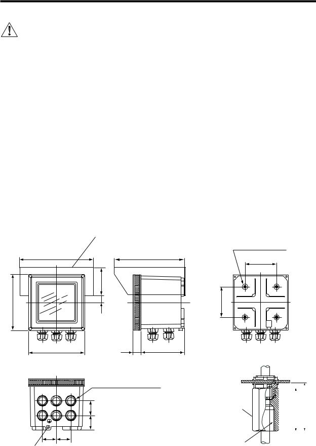
□Hood (optional)
Option code : /H□
|
|
|
Four M6 screws, 8 (0.31) deep |
184 |
220 |
|
80 |
(7.24) |
(8.66) |
|
|
|
|
|
(3.15) |
|
72 |
|
|
|
(2.83) |
|
|
144 |
20 (0.79) |
|
80 |
(5.67) |
|
|
|
|
|
|
(3.15) |
144 |
23 |
112 |
Adaptor for conduit work |
(5.67) |
(0.91) |
(4.41) |
|
|
|
|
(option code : /AFTG, /ANSI) |
|
|
|
Cable inlet port (21 (0.83) dia. holes) |
|
|
|
|
equivalent to DIN PG13.5 cable gland |
|
A |
B |
C |
|
A : For sensor cable |
|
|
|
|
B : For sensor cable |
|
|
|
36 (1.42) |
C : For output signal |
|
|
|
|
D : For contact output (S3 and S4) |
D |
E |
F |
38 (1.50) |
E : For contact output (S1 and S2) |
F : For power supply |
||||
36 |
36 |
|
|
|
(1.42) |
(1.42) |
|
|
Weight: Approx. 2 kg |
Ground terminal |
|
|
|
|
|
|
|
|
|
(M4 screw) |
|
|
|
|
Figure 3-1. Housing dimensions and layout of glands
Adaptor
G 1/2 female ( / AFTG) 1/2 NPT female ( / ANSI)
|
|
|
|
(2.17) |
|
|
|
|
|
||
|
|
|
|
||
|
49 |
|
|
55 |
|
|
|
|
Approx. |
||
|
(1.93) |
|
|
||
|
|
|
|
|
|
|
|
|
|
|
|
|
|
|
|
|
|
F17.ai
IM 12D08E02-01E

3-2 Installation and wiring |
|
|
|
|
|
|
Unit: mm (inch) |
23 |
(0.91) |
M6, 4 screws |
|
|
12 max.(panel thickness) |
Panel cutout dimensions |
|
|
|
||
|
(0.47) |
|
|
|
|
|
|
|
|
|
M5, 2 screws |
|
100 |
|
137+20 |
|
(3.94) |
|
(5.43) |
|
|
|
137+20 |
|
|
178 |
(5.43) |
|
|
(7.01) |
|
Figure 3-2. Panel mounting diagram (Option Code: /PM)
Example of bracket used for pipe mounting
188
(7.40)
174
(6.85)
50 |
(1.97) |
Nominal 50A (O.D 60.5mm) mounting pipe (2 inch)
Example of bracket used for wall mounting
135 13
|
|
|
|
|
(5.31) |
|
(0.51) |
||
|
|
|
|
|
224 |
(8.82) |
M6, 4 screws
200
(7.87)
100 |
(3.94) |
M6, 4 screws |
200 |
(7.87) |
35 (1.38) |
15 (0.59) |
70 (2.76) |
10mm dia., 3 holes |
100 (3.94) |
(0.39)
Figure 3-3. Wall and pipe mounting diagram (Option Code: /U)
IM 12D08E02-01E
Installation and wiring 3-3
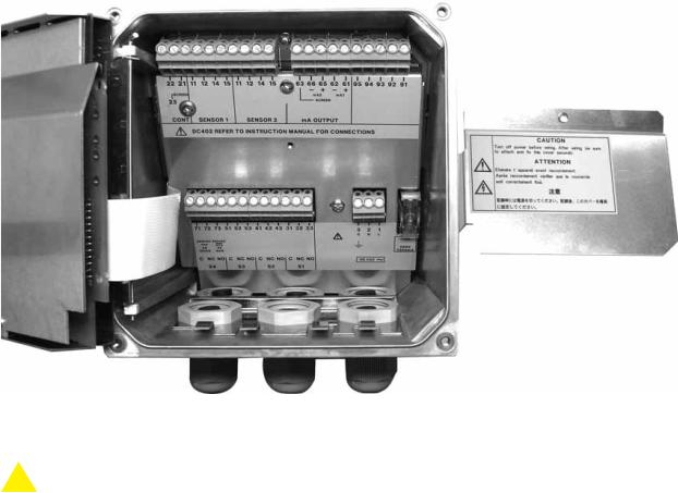
Figure 3-4. Internal view of EXA wiring compartment
 DANGER
• Never apply power to the DC402G converter and other instruments connected to the DC402G converter until all wiring is completed.
 WARNING
•This product complies with the CE marking.
Where compliance with the CE marking and relevant standard is necessary, the following wiring is required.
1.Install an external switch or circuit breaker to the power supply of the DC402G converter.
2.Use an external switch or circuit breaker rated 5A and conforming to IEC 60947-1 or IEC 60947-3.
3.It is recommended that the external switch or circuit breaker be installed in the same room as the DC402G converter.
4.The external switch or circuit breaker should be installed within reach of the operator and identified with marking as a power supply switch to the DC402G converter.
5.Power lines such as power cables and contact outputs should be fixed securely onto a wall or construction using cable racks, conduit tubing, nylon bands or other appropriate ways. Accidental removal from terminals by pulling may result in electric shock.
IM 12D08E02-01E
3-4 Installation and wiring
3-2. Preparation
Refer to figure 3-4. The relay contact terminals and power supply connections are under the screening
(shielding) plate. These should be connected first. Connect the sensor and outputs.
To open the EXA 402 for wiring:
1.Loosen the four frontplate screws and remove the cover.
2.Use the rubber knob in the lower righthand corner and swing open the display board to the left.
3.The upper terminal strip is now visible.
4.Remove the screen (shield) plate covering the lower terminal strip.
5.Connect the power supply and contact outputs. Use the three glands at the back for these cables.
6.Replace the screen (shield) plate over the lower terminals.
 WARNING
Always replace the screen plate over the power and contact outputs for safety and avoid interference.
7.Connect the analog output(s) and the sensor input.
8.Use the front three glands for analog output, sensor input, contact input and communication cabling (see figure 3-5).
9.Close the display board and switch on the power. Commission the instrument as required or use the default settings.
10.Replace the cover and secure frontplate with the four screws.
Tighten four frontplate screws to 1.5 N·m torque.
High voltage section
|
|
|
|
|
|
|
Contact |
|
Contact |
Sensor |
|
|
|
(S3,S4,FAIL) |
Sensor |
Power |
Analog |
|||
(S1,S2) |
||||||
cables |
||||||
output cables |
cables |
output cables |
cable |
output cable |
||
|
|
|
|
|
Suitable for cables with an outside diameter between 6 - 12 mm (0.24 - 0.47 in.)
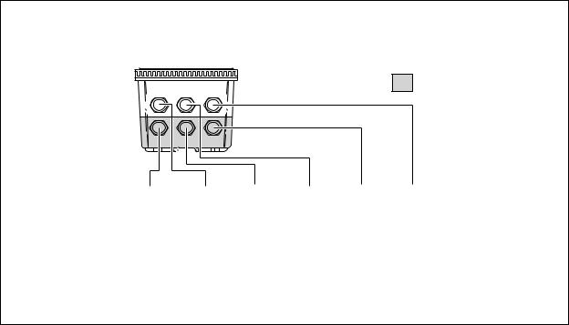
Figure 3-5. Glands to be used for cabling
IM 12D08E02-01E
Installation and wiring 3-5
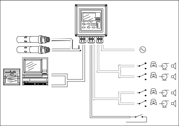
FRONT GLANDS |
REAR GLANDS |
Sensors
0/4-20 mA |
Output |
|
signals |
0/4-20 mA |
|
Power |
|
Contact |
S1 |
|
|
output |
|
|
S2 |
Figure 3-6. System configuration
3-3. Wiring the power supply
3-3-1. General precautions
Make sure the power supply is switched off. Also, make sure that the power supply is correct for the specifications of the EXA and that the supply agrees with the voltage specified on the nameplate. Remove the front cover by unscrewing the four screws to check this nameplate on the top of the display board.
Local health and safety regulations may require an external circuit breaker to be installed. The instrument is protected internally by a fuse. The fuse rating is dependent on the supply to the instrument. The
250 VAC fuses should be of the “time-lag” type, conforming to IEC60127.
The internal fuse is located next to the power terminals (in the lower right hand corner).
 DANGER
Use only a fuse of the specified current, voltage and type ratings to prevent fire. For fuse replacement, refer to Section 7-3, “Fuse Replacement.”
3-3-2. Access to terminal and cable entry
Terminals 1 and 2 on the bottom terminal strip are used for the power supply. Guide the power cables through the gland closest to the power supply terminals. The terminals will accept wires of 2.5 mm2 (14 AWG). Use cable finishings if possible.
Connect the wires as indicated in the wiring diagram (refer to figure 3-6).
IM 12D08E02-01E
3-6 Installation and wiring
|
|
|
|
|
|
|
Sensor inputs |
|
|
|
|
|
|
|
|
|
|
|
|
|
|
|
|
|
mA Outputs |
|
|
|
|
|
|
|
|
|
|
|
|
|
|
|
|
|
|
|
|
|
|
|
|
|
|
|
|
|||||||||||||||||
|
|
|
|
|
|
|
|
|
|
|
|
|
|
|
|
|
|
|
|
|
|
|
|
|
|
|
|
|
|
|
|
|
|
|
|
|
|
|
|
|
|
|
|
|
|
|
|
|
|
|
|
|
|
|||||||||||||||||
|
|
|
|
|
|
|
|
|
|
|
|
|
|
|
|
|
|
|
|
|
|
|
|
|
|
|
|
|
|
|
|
|
|
|
|
|
|
|
|
|
|
|
|
|
|
|
|
|
|
|
|
|
|
|||||||||||||||||
21 |
|
11 |
12 |
14 |
15 |
|
11 |
12 |
14 |
15 |
|
|
63 |
66 |
65 |
62 |
61 |
|
95 |
94 |
93 |
92 |
91 |
|||||||||||||||||||||||||||||||||||||||||||||||
22 |
|
|
|
|
|
|||||||||||||||||||||||||||||||||||||||||||||||||||||||||||||||||
|
|
|
|
|
|
|
|
|
|
|
|
|
|
|
|
|
|
|
|
|
|
|
|
|
|
|
|
|
|
|
|
|
|
|
|
|
|
|
|
|
|
|
|
|
|
|
|
|
|
|
|
|
|
|
|
|
|
|
|
|
|
|
|
|
||||||
Screen |
|
|
|
|
|
|
|
|
|
|
|
|
|
|
|
|
|
|
|
|
|
|
|
|
|
|
|
|
|
|
|
|
|
|
|
|
mA2 |
|
|
|
mA1 |
|
|
|
|
|
|
|
|
|
|
|
|
|
|
|
|
|||||||||||||
|
|
|
|
|
|
|
|
|
|
|
|
|
|
|
|
|
|
|
|
|
|
|
|
|
|
|
|
|
|
|
|
|
|
|
|
|
|
|
|
|
|
|
Screen |
|
|
|
|
|
|
|
|
|
|
|
|
|
|
|
|
|
|
|
||||||||
23 |
|
|
|
|
|
Temp |
|
|
|
|
|
|
|
|
Temp |
|
|
|
|
|
|
|
|
|
|
|
|
|
|
|
|
|
|
|
|
|
|
|
|
|
|
|
|
|
|
|
|
|
|
|
||||||||||||||||||||
|
|
|
|
|
|
|
|
|
|
|
|
|
|
|
|
|
|
|
|
|
|
|
|
|
|
|
|
|
|
|
|
|
|
|
|
|
|
|
|
|
|
|
|
|
|
|
|
|
|
|
|
|
|
|
|
|
||||||||||||||
CONT |
|
|
|
|
SENSOR 1 |
|
|
|
|
|
SENSOR 2 |
|
|
|
|
|
mA OUTPUT |
|
|
|
|
|
|
|
|
|
|
|
|
|
|
|
|
|
|
|
||||||||||||||||||||||||||||||||||
|
|
|
|
|
|
|
|
|
DC402 REFER TO INSTRUCTION MANUAL FOR CONNECTIONS |
|
|
|
|
|
|
|
|
|||||||||||||||||||||||||||||||||||||||||||||||||||||
|
|
|
|
|
|
|
|
|
|
|
|
|
|
|
|
|
|
|
|
|
|
|
|
|
|
|
|
|
|
|
|
|
|
|
|
|
|
|
|
|
|
|
|
|
|
|
|
|
|
|
|
|
|
|
|
|
|
|
|
|
|
|||||||||
|
Relay Contacts |
|
|
|
|
|
|
|
|
|
|
|
|
|
|
|
|
|
|
|
|
|
|
|
|
|
|
|
|
|
|
Power Supply |
|
|
|
|
|
|
|
|
|
|
|
|
|
|
||||||||||||||||||||||||
|
|
|
|
|
|
|
|
|
|
|
|
|
|
|
|
|
|
|
|
|
|
|
|
|
|
|
|
|
|
|
|
|
|
|
|
|
|
|
|
|
|
|
|
|
|
|
|
|
|
|
|
|
|
|
|
|
|
|
|
|
|
|
|
|
|
|
|
|
|
|
|
|
|
|
|
|
|
|
|
|
|
|
|
|
|
|
|
|
|
|
|
|
|
|
|
|
|
|
|
|
|
|
|
|
|
|
|
|
|
|
|
|
|
|
|
|
|
|
|
|
|
|
|
|
|
|
|
|
|
|
|
|
|
|
|
|
|
|
|
|
|
|
71 |
|
72 |
|
73 |
|
|
51 |
|
52 |
|
53 |
|
|
41 |
|
42 |
|
43 |
|
|
31 |
32 |
|
33 |
|
|
|
|
|
|
|
|
|
|
|
3 |
|
|
|
2 |
|
1 |
|
|
|
|
|
|
|
|
|
||||||||||||||||||
|
|
|
|
|
|
|
|
|
|
|
|
|
|
|
|
|
|
|
|
|
|
|
|
|
|
|
|
|
|
|
|
|
|
|
|
|
|
|
|
|
|
|
|
|
|
|
|
|
|
|
|
G |
N |
L |
|
|
|
|
|
|
|
|
||||||||
|
250VAC |
250VDC |
|
|
|
|
|
|
|
|
|
|
|
|
|
|
|
|
|
|
|
|
|
|
|
|
|
|
|
|
|
|
|
|
|
|
|
|
|
|
|
|
|
FUSE |
|
|
|
|||||||||||||||||||||||
|
|
|
|
|
|
|
|
|
|
|
|
|
|
|
|
|
|
|
|
|
|
|
|
|
|
|
|
|
|
|
|
|
|
|
|
|
|
|
|
|
|
|
|
|
|
|
|
|
|
|
|
|
|
|
|
|||||||||||||||
|
|
|
|
|
|
|
|
|
|
|
|
|
|
|
|
|
|
|
|
|
|
|
|
|
|
|
|
|
|
|
|
|
|
|
|
|
|
|
|
|
|
|
|
|
|
|
|
|
|
|
|
|
|
|
|
|||||||||||||||
|
|
5A |
|
|
|
|
5A |
|
|
|
|
|
|
|
|
|
|
|
|
|
|
|
|
|
|
|
|
|
|
|
|
|
|
|
|
|
|
|
|
|
|
|
|
|
|
|
|
|
|
|
|
|
|
|
|
|
|
|
|
|
|
|
|
|
|
|||||
|
100VA |
|
50W |
|
|
|
|
|
|
|
|
|
|
|
|
|
|
|
|
|
|
|
|
|
|
|
|
|
|
|
|
|
|
|
|
|
|
|
|
|
|
|
|
|
|
|
|
|
|
|
|
|
|
|
|
|
|
|
|
|
|
|||||||||
|
|
|
|
|
|
|
|
|
|
|
|
|
|
|
|
|
|
|
|
|
|
|
|
|
|
|
|
|
|
|
|
|
115 VAC |
|
|
|
|
|
|
|
|
|
250VAC; T 200mA |
|
|
|
||||||||||||||||||||||||
|
C |
|
NC NO |
|
C NC NO |
|
C NC NO |
|
C |
NC |
NO |
|
|
|
|
|
|
|
|
|
|
|
|
|
|
|||||||||||||||||||||||||||||||||||||||||||||
|
|
|
|
|
|
|
|
|
|
|
|
|
|
|
|
|
|
|
||||||||||||||||||||||||||||||||||||||||||||||||||||
|
|
|
|
|
|
|
230VAC |
|
|
|
|
|
|
|
|
|
250VAC; T 100mA |
|
|
|
||||||||||||||||||||||||||||||||||||||||||||||||||
|
|
|
|
S4 |
|
|
|
|
|
|
|
|
|
S3 |
|
|
|
|
|
|
|
|
S2 |
|
|
|
|
|
|
S1 |
|
|
|
|
|
|
|
|
|
|
|
|
|
|
|
|
|
|
|
|
|
|
|
|
|
|
|
|
|
|
|
|
||||||||
|
|
|
|
|
|
|
|
|
|
|
|
|
|
|
|
|
|
|
|
|
|
|
|
|
|
|
|
|
|
|
|
|
|
|
|
|
|
|
|
|
|
|
|
|
|
|
|
|
|
|
|
|
|
|
|
|
|
|
||||||||||||
Figure 3-7. Input and output connections
3-3-3. AC power
Connect terminal 1 to the phase line of the AC power and terminal 2 to the zero line. The size of conductors should be at least 1.25 mm2. The overall cable diameter should be between 6 & 12 mm (0.24 & 0.47 in).
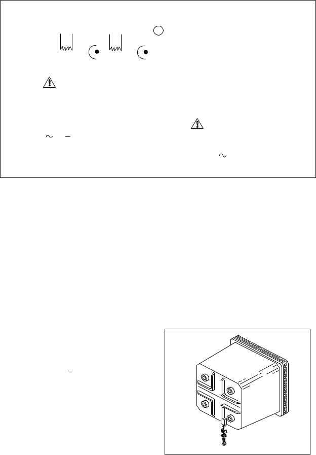
3-3-4. Grounding the housing
 DANGER
Protective grounding must be made to prevent electric shock.
To protect the instrument against interference, the housing should be connected to ground by a large area conductor. This cable can be fixed to the rear of the housing using a braided wire cable.
See figure 3-8.
 CAUTION
Please be sure to connect protective grounding of DC402G with cable of 1.25 mm2 or larger cross section in order to avoid the electrical shock to the operators and maintenance engineers and prevent the influence of external noise. And further connect the grounding wire to the  mark (100Ω or less).
3-3-5. Switching on the instrument
After all connections are made and checked, the power can be switched on from the power supply.
Make sure the LCD display comes on. All segments will illuminate, then the instrument will momentarily display its unique serial number. After a brief interval, the display will change to the measured value. If errors are displayed or a valid measured value is not shown, consult the troubleshooting section (Chapter 8) before calling Yokogawa.
(M4 screw)
Figure 3-8. Grounding the housing
IM 12D08E02-01E
Installation and wiring 3-7
3-4. Wiring the contact signals
3-4-1. General precautions
The contact output signals consist of voltage-free relay contacts for switching electrical appliances
(SPDT). They can also be used as digital outputs to signal processing equipment (such as a controller or PLC). It is possible to use multi-core cables for the contact in and output signals and shielded multi-core cable for the analog signals.
3-4-2. Contact outputs
The EXA unit’s four contact outputs can be wired to suit your own custom requirements (Figure 3-6).
In the Non-Alarm or Power Off states, contacts S1, S2 and S3 are OFF, Common (C) and Normally Closed (NC) are in contact.
In the “Fail” or Power Off states, contact S4 is ON, Common (C) and Normally Closed (NC) are in contact.
You can either use them to switch AC power, or switch a DC Voltage for digital interfacing.
Default settings
•The contact S1 is pre-programmed for high alarm function.
•The contact S2 is pre-programmed for a low alarm function.
•The contact S3 is not activated as an alarm (off).
•The contact S4 is pre-programmed for FAIL.
The three control contacts (S1 to S3) can be used for simple process control by programming their function (Chapter 5). The FAIL contact is programmed to signal a fault in the measuring loop. Always connect the FAIL contact to an alarm device such as a warning light, sound annunciator, or alarm panel to make full use of the fault detection possibilities (self diagnostics) of the EXA converter.
3-4-3. Contact input
It is necessary to use screening/shielding on the output signal cables. Screw (M3) 23 is used to connect the shielding.
3-5. Wiring the analog output signals
3-5-1. General precautions
The analog output signals of the EXA transmit low power standard industry signals to peripherals like control systems or strip-chart recorders (Figure 3-6).
3-5-2. Analog output signals
The output signals consist of active current signals of either 0-20 mA or 4-20 mA. The maximum load can be 600 ohms on each.
It is necessary to use screening/shielding on the output signal cables. Terminal 63 is used to connect the shielding.
IM 12D08E02-01E
3-8 Installation and wiring
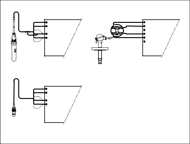
3-6. Sensor wiring
Refer to figure 3-9, which includes drawings that outline sensor wiring.
The EXA DC402G can be used with a wide range of commercially available sensor types if provided with shielded cables, both from Yokogawa and other manufacturers. The sensor systems from Yokogawa fall into two categories, the ones that use fixed cables and the ones with separate cables.
To connect sensors with fixed cables, simply match the terminal numbers in the instrument with the identification numbers on the cable ends.
Note that the DC402G uses the 2 electrode measuring principle. Yokogawa sensors and cables are prepared for compatibility with 4-electrode measuring systems. To avoid problems either cut off and insulate the wires tagged 13 &16 or connect the wires in tandem 13 &14 into terminal 14 or 15 &16 into terminal
15.
CONDUCTIVITY RESISTIVITY CONVERTER |
|
|
|
|
|
11 TEMPERATURE |
|
BROWN |
11 TEMPERATURE |
||
|
BROWN |
||||
12 TEMPERATURE |
1 |
12 TEMPERATURE |
|||
2 |
|
||||
|
|
|
|
|
|
14 CELL |
1 |
YELLOW/GREEN |
14 |
OUTER ELECTRODE |
|
2 |
|
||||
15 CELL |
|
15 |
INNER ELECTRODE |
||
|
RET |
||||
|
|
|
|
|
|
SEPARATE SENSORS WITH WU40-LH.. CABEL |
|
|
SX42-SX . . - . F SENSORS |
||
|
|
|
|
||
|
|
|
NOTE: Use shielded cable |
||
11 TEMPERATURE |
|
|
|
|
|
12 TEMPERATURE |
|
|
|
|
|
14 |
OUTER ELECTRODE |
|
|
|
|
15 |
INNER ELECTRODE |
|
|
|
|
SC4A... SENSORS WITH INTEGRATED CABEL |
|
|
|
|
|
Figure 3-9. Sensor wiring diagrams
3-7. Sensor connection using junction box and extension cable
Where a convenient installation is not possible using the standard cables between sensors and converter, a junction box and extension cable may be used. The Yokogawa BA10 junction box and the WF10 extension cable should be used. These items are manufactured to a very high standard and are necessary to ensure that the specifications of the system can be met. The total cable length should not exceed
60 metres (e.g. 10 m fixed cable and 50 m extension cable).
NOTE: Numbers 17 of both WF10 and BA10 do not need to be used.
IM 12D08E02-01E
Installation and wiring 3-9
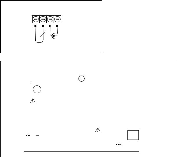
3-8. Other sensor systems
To connect other sensor systems, follow the general pattern of the terminal connections as listed below:
11 and 12 Always used for temperature compensation resistor input (Pt1000, Ni100, Pt100, PB36 and 8k55)
14Normally used for the outer electrode
15Used for inner electrode
In case a 4-electrode measuring system will be used, 14 and 16 should be used for the current electrodes.Please ensure that shielded cabling will be used.
In figure 3-10 this is shown in a schematic way.
11 12 14 15
TEMPERATURE |
|
|
t |
|
|
|
|
|
|
|
|
|
CELL |
|
|
|
|
|
|
|
|
|
|
|
|
|
|
|
|
|
|
|
|
|
|
|
|
||||||
SENSOR |
|
|
|
|
|
|
|
|
|
|
|
|
|
ELECTRODE |
|
|
|
|
|
|
|
|
|
|
|
|
|
|
|
|
|
|
|
|
|||||||||
|
|
|
|
|
|
|
|
|
|
|
|
|
|
|
|
|
|
|
|
|
|
|
|
|
|
|
|
|
|
|
|
|
|||||||||||
|
|
|
2-electrode configuration |
|
|
|
|
|
|
|
|
|
|
|
|
|
|
|
|
|
|
|
|
|
|
|
|
||||||||||||||||
|
|
|
|
|
|
|
|
|
|
|
|
|
|
|
|
|
|
|
|
|
|
|
|
|
|
|
|
|
|
|
|
|
|
|
|
||||||||
Figure 3-10. Connection diagram for other sensors |
|
|
|
|
|
|
|
|
|
|
|
|
|
|
|
|
|
|
|
|
|
|
|||||||||||||||||||||
|
|
|
|
|
|
|
|
|
|
|
|
|
|
|
|
|
|
|
|
|
|
|
|
|
|
|
|
|
|
||||||||||||||
|
|
|
|
|
|
|
|
Sensor Inputs |
|
|
|
|
mA Outputs |
|
|
|
|
|
|
|
|
|
|
|
|
|
|
|
|
||||||||||||||
|
|
|
|
|
|
|
|
|
|
|
|
|
|
|
|
|
|
|
|
|
|
|
|
|
|
|
|
|
|
|
|
|
|
|
|
|
|
|
|
|
|
||
|
|
|
|
|
|
|
|
|
|
|
|
|
|
|
|
|
|
|
|
|
|
|
|
|
|
|
|
|
|
|
|
|
|
|
|
|
|
|
|
|
|
|
|
|
22 |
21 |
11 |
12 |
14 |
15 |
11 |
12 |
14 |
15 |
63 |
66 |
65 |
62 |
61 |
|
95 |
94 |
93 |
92 |
91 |
|
|||||||||||||||||||||
|
|
SCREEN |
|
|
|
|
|
|
|
|
|
|
|
|
|
|
|
|
|
|
|
|
|
|
|
|
|
|
|
|
|
|
|
|
|
|
|
|
|
||||
|
|
|
|
|
|
|
|
|
|
|
|
|
|
|
|
|
|
|
|
|
|
mA2 |
|
mA1 |
|
|
|
|
|
|
|
|
|
|
|
|
|
||||||
|
|
|
|
|
|
|
|
|
|
|
|
|
|
|
|
|
|
|
|
|
|
|
|
|
|
|
|
|
|
|
|
|
|
|
|
||||||||
|
|
|
|
|
|
|
|
|
|
|
|
|
|
|
|
|
|
|
|
|
|
|
|
|
|
SCREEN |
|
|
|
|
|
|
|
|
|
|
|
|
|
|
|||
|
23 |
|
|
|
|
|
|
|
|
|
|
|
|
|
|
|
|
|
|
|
|
|
|
|
|
|
|
|
|
|
|
|
|
|
|
|
|
|
|||||
|
|
|
|
|
|
|
|
|
|
|
|
|
|
|
|
|
|
|
|
|
|
|
|
|
|
|
|
|
|
|
|
|
|
|
|
|
|
|
|
|
|
||
|
CONT |
|
|
SENSOR 1 |
|
|
SENSOR 2 |
|
mA OUTPUT |
|
|
|
|
|
|
|
|
|
|
|
|
|
|
||||||||||||||||||||
|
|
|
|
|
|
|
|
|
|
|
|
|
|
|
|
|
|
|
|
||||||||||||||||||||||||
|
|
|
|
|
DC402 REFER TO INSTRUCTION MANUAL FOR CONNECTIONS |
|
|
|
|
|
|
|
|
|
|
|
|||||||||||||||||||||||||||
|
|
|
|
|
|
|
|
|
|
|
|
|
|
|
|
|
|
|
|
|
|
|
|
|
|
|
|
|
|
|
|
|
|
|
|
|
|
|
|
|
|
|
|
|
|
Relay Contacts |
|
|
|
|
|
|
|
|
|
|
|
|
|
|
Power Supply |
|
|
|
|
||||||||||||||||||
|
|
|
|
|
|
|
|
|
|
|
|
|
|
|
|
|
|
|
|
|
|
|
|
|
|
|
|
|
|
|
|
|
|
|
|
|
|
|
|
|
|
|
|
|
|
|
|
|
|
|
|
|
|
|
|
|
|
|
|
|
|
|
|
|
|
|
|
|
|
|
|
|
|
|
|
|
|
|
|
71 |
72 |
73 |
|
|
51 |
52 |
53 |
41 |
42 |
43 |
31 |
32 |
33 |
3 |
|
2 |
1 |
|
|
||||||||||||||||||||
|
|
|
|
|
|
|
|
|
|
|
|
|
|
|
|
|
|
|
|
|
|
|
|
|
|
|
|
|
|
|
|
||||||||
250VAC |
250VDC |
|
|
|
|
|
|
|
|
|
|
|
|
|
|
|
|
|
|
|
|
|
|
G |
N |
L |
|
||||||||||||
|
|
|
|
|
|
|
|
|
|
|
|
|
|
|
|
|
|
|
|
|
|||||||||||||||||||
|
|
|
|
|
|
|
|
|
|
|
|
|
|
|
|
|
|
|
|
|
|
|
|
|
|
|
|
|
|
|
|||||||||
|
|
|
|
|
|
|
|
|
|
|
|
|
|
|
|
|
|
|
|
|
|
|
|
|
|
|
|
|
|
|
|||||||||
|
5A |
|
|
|
5A |
|
|
|
|
|
|
|
|
|
|
|
|
|
|
|
|
|
|
|
|
|
|
|
|
|
|
|
|
|
|
|
|
||
|
|
|
|
|
|
|
|
|
|
|
|
|
|
|
|
|
|
|
|
|
|
|
|
|
|
|
|
|
|
|
|
|
|
|
|||||
|
|
|
|
|
|
|
|
|
|
|
|
|
|
|
|
|
|
|
|
|
|
|
|
|
|
|
|
|
|
|
|
|
|
|
|||||
|
|
|
|
|
|
|
|
|
|
|
|
|
|
|
|
|
|
|
|
|
|
|
|
|
|
|
|
|
|
|
|
|
|
||||||
100VA |
50W |
|
|
|
|
|
|
|
|
|
|
|
|
|
|
|
|
|
|
|
|
|
|
|
|
|
|
|
|
|
|
|
|||||||
C NC NO |
|
C NC NO |
|
C |
NC NO |
|
C |
NC NO |
|
|
|
|
|
|
|
||||||||||||||||||||||||
|
|
|
|
|
115 VAC |
|
|
|
|
||||||||||||||||||||||||||||||
|
|
S4 |
|
|
|
|
|
|
|
S3 |
|
|
|
|
|
S2 |
|
|
|
|
|
S1 |
|
|
|
|
|
|
|
|
|
|
|
|
|
||||
FUSE
250V
T200mA
Figure 3-11. Terminal identification labels example
IM 12D08E02-01E
3-10 Installation and wiring
Figure 3-12. Sensor cable connections
IM 12D08E02-01E

Operation 4-1
4. Operation; Display Functions And Setting
4-1. Operator interface
This section provides an overview of the operation of the EXA operator interface. The basic procedures for obtaining access to the three levels of operation are described briefly. For a step-by-step guide to data entry, refer to the relevant section of this instruction manual. Figure 4-1 shows the EXA operator interface.
LEVEL 1: Maintenance
These functions are accessible by pushbutton through a flexible front cover window. The functions make up the normal day-to-day operations that an operator may be required to complete. Adjustment of the display and routine calibration are among the features accessible in this way. (See table 4-1).
LEVEL 2: Commissioning
A second menu is exposed when the EXA front cover is removed and the display board is revealed.
Users gain access to this menu by pressing the button marked *in the lower right of the display board. This menu is used to set such values as the output ranges and hold features. It also gives access to the service menu. (See table 4-1).
LEVEL 3: Service
For more advanced configuration selections, press the button marked *, then press “NO” repeatedly until you reach SERVICE. Now push the “YES” button. Selecting and entering “Service Code” numbers in the commissioning menu provide access to the more advanced functions. An explanation of the Service Codes is listed in chapter 5 and an overview table is shown in chapter 10.
Table 4-1. Operations overview
|
Routine |
Function |
Chapter |
Maintenance |
SETPOINTS |
Adjust alarm setpoints (when activated) |
5 |
|
CALIB 1(2) |
Calibration with a standard solution or a sample |
6 |
|
DISPLAY 1(2) |
Read auxiliary data or set message display |
4 |
|
HOLD |
Switch hold on/off (when activated) |
5 |
Commissioning |
SETPOINTS |
Adjust alarm setpoints |
5 |
|
RANGE |
Adjust the output range |
5 |
|
SET HOLD |
Activate the hold function |
5 |
|
TEMP |
Select method of temperature compensation |
5 |
Service |
SERVICE |
Fine tune the specialized functions of the |
5 |
(Access to coded entries |
|
converter |
|
from the commissioning |
|
|
|
level) |
|
|
|
Note:
All three levels may be separately protected by a password. See Service Code 52 in chapter 5 Service Code table for details on setting passwords.
IM 12J05D02-01E
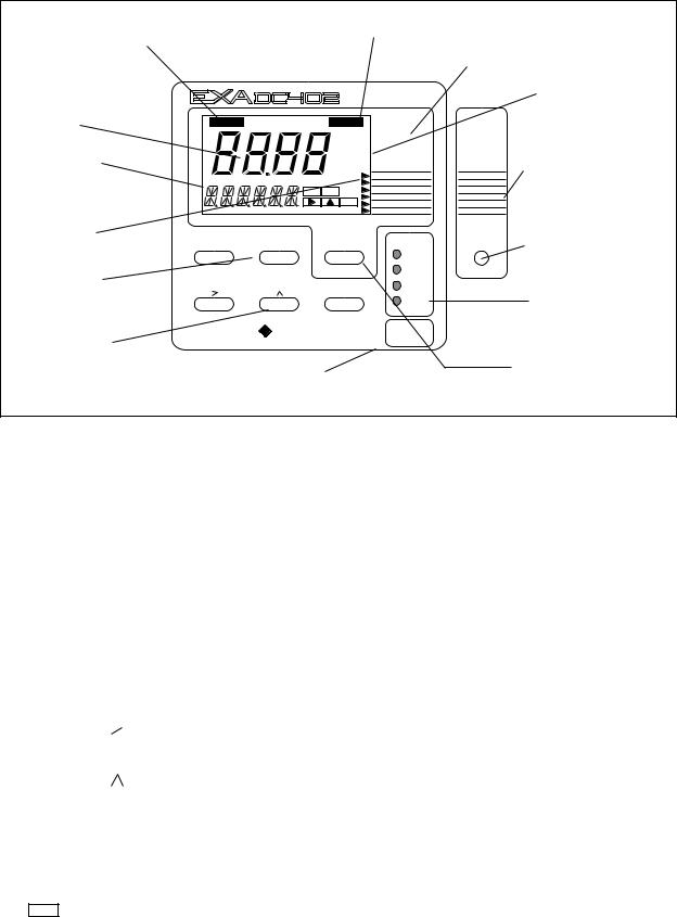
4-2 Operation
Output hold flag |
Fail flag |
|
Menu pointer flags
Units
Main display
Message display
Key prompt flags
Selection keys
YES |
: Accept setting |
NO |
: Change setting |
Adjustment keys
>: Choose digit to adjust
^: Adjust digit
ENT : Confirm change
HOLD |
|
FAIL |
MODE |
|
|
|
|
c m |
|
|
|
|
|
m S / c m |
|
|
|
|
|
c m |
|
|
Commissioning |
|
|
S / c m |
|
|
|
|
|
|
MEASURE |
SETPOINTS |
function menu |
|
|
|
CAL 1 |
|
|
|
YES |
NO |
CAL 2 |
RANGE |
|
|
DISPLAY 1 |
SET HOLD |
|
||
|
|
ENT |
|
||
|
|
DISPLAY 2 |
TEMP. |
|
|
|
|
|
HOLD |
SERVICE |
|
YES |
NO |
MODE |
CONTACTS |
* |
Commissioning |
|
|
|
|
||
|
|
|
S1 |
mode access key |
|
|
|
|
|
|
|
|
|
|
S2 |
|
|
|
|
ENT |
S3 |
|
Relay contact |
|
|
FAIL |
|
||
|
|
|
|
status indicators |
|
|
|
|
|
|
|
YOKOGAWA |
|
|
MARKINGS |
|
|
|
|
WITHIN |
|
|
|
|
|
|
INCLOSURE |
|
|
Measure/Maintenance
Broken line indicates area mode key that can be seen through
front cover
Figure 4-1. DC402G operator interface
4-2. Explanation of operating keys
MODE key This key toggles between the Measuring and Maintenance modes. Press once to obtain access to the maintenance function menu.
SETPOINTS
CAL.1/CAL.2
DISP.1/DISP.2 HOLD
Press again to return to the Measuring mode (press twice when hold is activated).
YES/NO keys These are used to select choices from the menu.
YES |
is used to accept a menu selection. |
NO |
is used to reject a selection, or to move ahead to the next option. |
DATA ENTRY keys (
ENT
*key

 ENT)
ENT)
is used as a “cursor” key. Each press on this key moves the cursor or flashing digit one place to the right. This is used to select the digit to be changed when entering numerical data.
is used to change the value of a selected digit. Each press on this key increases the value by one unit. The value can not be decreased, so in order to obtain a lower value, increase past nine to zero, then increase to the required number. When the required value has been set using the > and ^ keys, press ENT to confirm the data entry. Please note that the EXA 402 does not register any change of data until the ENT key is pressed.
This is the Commissioning mode key. It is used to obtain access to the Commissioning menu. This can only be done with the cover removed or opened.
Once this button has been used to initiate the Commissioning menu, follow the prompts and use the other keys as described above.
IM 12J05D02-01E

Operation 4-3
4-3. Setting passcodes
In Service Code 52, EXA users can set passcode protection for each one of the three operating levels, or for any one or two of the three levels. This procedure should be completed after the initial commissioning (setup) of the instrument. The passcodes should then be recorded safely for future reference.
When passcodes have been set, the following additional steps are introduced to the configuration and programming operations:
Maintenance
Press MODE key.The display shows 000 and *PASS*
Enter a 3-digit passcode as set in Service Code 52 to obtain access to the Maintenance Mode
Commissioning
Press * key. The display shows 000 and *PASS*
Enter a 3-digit passcode as set in Service Code 52 to obtain access to the Commissioning Mode.
Service
From the commissioning menu, select *Service by pressing YES key. The display shows 000 and *PASS*
Enter a 3-digit passcode as set in Service Code 52 to obtain access to the Service Mode.
NOTE:
See Service Code 52 for the setting of passcodes.
4-4. Display example
The next page shows the sequence of button presses and screens displayed when working in default configuration.
More or less options will be made available by the configuration of some service codes, or by choices made in the Commissioning menu.
The following deviations are possible:
Items marked are omitted when switched off in commissioning mode and/or service code 51.
Temperature compensation will be displayed dependent on chosen compensation method: NaCl, TC 2.1 or matrix.


 DISP.2 only appears if mA2 is configured for a 2nd (different) temperature compensation or if % by weight.2 is enabled in code 55.


 W/W % only appears if switched on in service code 55.
IM 12J05D02-01E
Loading...