


User’s
Manual
Model PH100
Panel Mount pH Converter
IM 12B11A01-01E
IM 12B11A01-01E
1st Edition
Safety Precautions
r Introduction
This manual covers the specifications, installation, operation and maintenance of the panel-mount version of the PH100 pH converter. Please read this before using the PH100. There are manuals for the related EXA100 series as follows:
Refer to them as required.
Model code |
Manual Name |
|
IM No. |
PH100 |
Panel Mount pH Converter |
IM 12 B11A01-01E |
|
OR100 |
Panel Mount ORP Converter |
IM 12 C11A01-01E |
|
SC100 |
Panel Mount Conductivity Converter |
IM 12 D11A01-01E |
|
PH10FP |
KCl Refillable pH Sensor |
IM 12 B11C01-01E |
|
PH10RP |
KCl Replenish-free pH Sensor |
IM 12 B11C02-01E |
|
OR10FP |
KCl Refillable ORP Sensor |
IM 12 C11C01-01E |
|
OR10RP |
KCl Replenish-free ORP Sensor |
IM 12 C11C02-01E |
|
SC10XB |
Conductivity Sensor for SC100 |
IM 12 D11C01-01E |
|
WTB100 |
Terminal Box for EXA100 |
IM 12 B11E01-01E |
|
WF100 |
Extension Cable for EXA100 |
IM 12 |
B11F01-01E |
PH10HLD |
Immersion Holder for EXA100 |
IM 12 |
B11D01-01E |
PH10HG |
Guide-pipe Holder for EXA100 |
IM 12 |
B11D02-01E |
T000.eps
IM 12B11A01-01E
1st Edition: Apr. 2003 (YK)
All Rights Reserved, Copyright © 2003, Yokogawa Electric Corporation
IM 12B11A01-01E
i

rFor the safe use of this equipment
(1)About This Manual
•This manual should be passed on to the end user.
•The contents of this manual are subject to change without prior notice.
•The contents of this manual shall not be reproduced or copied, in part or in whole, without permission.
•This manual explains the functions contained in this product, but does not warrant that they will suit the particular purpose of the user.
•Every effort has been made to ensure accuracy in the preparation of this manual. However, should any errors or omissions come to the attention of the user, please contact the nearest Yokogawa Electric representative or sales office.
•This manual does not cover the special specifications. This manual may be left unchanged on any change of specification, construction or parts when the change does not affect the functions or performance of the product.
•If the product is used in a manner not specified in this manual, the safety of this product may be impaired.
(2) Safety and Modification Precautions
• Follow the safety precautions in this manual when using the product to ensure protection and safety of personnel, product and system containing the product.
(3) The following safety symbols are used on the product as well as in this manual.
DANGER
This symbol indicates that the operator must follow the instructions laid out in this manual in order to avoid the risk of personnel injury, electric shock, or fatalities. The manual describes what special care the operator must exercise to avoid such risk.
 WARNING
This symbol indicates that the operator must refer to the instructions in this manual in order to prevent the instrument (hardware) or software from being damaged, or a system failure from occurring.
 CAUTION
This symbol draws attention to information essential for understanding the operation and functions.
Tip
This symbol gives information that complements the current topic.
SEE ALSO
This symbol identifies a source to which to refer.
Protective Ground Terminal
Function Ground Terminal (Do not use this terminal as the protective ground terminal.)
Alternating current
ii |
IM 12B11A01-01E |
Safety Precautions
rNOTICE and Cautions
•Check specifications
When the instrument arrives, unpack the package with care and check that the instrument has not been damaged during transportation. In addition, please check that the specification matches the order, and required accessories are not missing. Specifications can be checked by the model codes on the nameplate. Refer to Chapter 1.2 Specifications for the list of model codes.
•Details on operation parameters
When the PH100 panel mount pH Converter at the user site, it will operate based on the operation parameters (initial data Table 5.1 to 5.5) set before shipping from the factory.
Ensure that the initial data is suitable for the operation conditions before conducting analysis. Where necessary, set the instrument parameters for appropriate operation. For details of setting data, refer to chapters 4 to 5.
When user changes the operation parameters, it is recommended to note down the changed setting data.
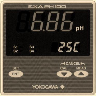
Front Panel of PH100
IM 12B11A01-01E |
iii |

LED Display Symbols
• Alphanumerics are represented as follows on the LED display
Alphanumerics LED Display Alphanumerics LED Display Alphanumerics LED Display
A |
N |
0 |
B |
O |
1 |
C |
P |
2 |
D |
Q |
3 |
E |
R |
4 |
F |
S |
5 |
G |
T |
6 |
H |
U |
7 |
I |
V |
8 |
J |
W |
9 |
K |
X |
|
L |
Y |
|
M |
Z |
|
iv |
IM 12B11A01-01E |
Safety Precautions
r After-sales Warranty
dDuring the warranty period, for repair under warranty carry or send the product to the local sales representative or service office. Yokogawa will replace or repair any damaged parts and return the product to you.
dBefore returning a product for repair under warranty, provide us with the model name and serial number and a description of the problem. Any diagrams or data explaining the prpoblem would also be appreciated.
dIf we replace the product with a new one, we won’t provide you with a repair report.
dYokogawa warrants the product for the period stated in the pre-purchase quotation. Yokogawa shall conduct defined warranty service based on its standard. When the customer site is located outside of the service area, a fee for dispatching the maintenance engineer will be charged to the customer.
dIn the following cases, customer will be charged repair fee regardless of warranty period.
•Failure of components which are out of scope of warranty stated in instruction manual.
•Failure caused by usage of software, hardware or auxiliary equipment, which Yokogawa Electric did not supply.
•Failure due to improper or insufficient maintenance by user.
•Failure due to modification, misuse or outside-of-specifications operation which Yokogawa does not authorize.
•Failure due to power supply (voltage, frequency) being outside specifications or abnormal.
•Failure caused by any usage out of scope of recommended usage.
•Any damage from fire, earthquake, storms and floods, lightning, disturbances, riots, warfare, radiation and other natural changes.
dYokogawa does not warrant conformance with the specific application at the user site. Yokogawa will not bear direct/indirect responsibility for damage due to a specific application.
dYokogawa Electric will not bear responsibility when the user configures the product into systems or resells the product.
dMaintenance service and supplying repair parts will be covered for five years after the production ends. For repair for this product, please contact the nearest sales office described in this instruction manual.
IM 12B11A01-01E |
v |
vi |
IM 12B11A01-01E |

Contents
r Introduction ...................................................................................................................... |
|
|
i |
|
r For the safe use of this equipment ................................................................................ |
ii |
|||
r NOTICE and Cautions |
.................................................................................................. |
iii |
||
r After-sales Warranty ...................................................................................................... |
|
v |
||
1. |
Overview ..................................................................................................................... |
|
|
1-1 |
|
1.1 |
EXA ..............................................................................PH100 pH converter |
1-1 |
|
|
1.2 |
Check .................................................................................the specifications |
1-1 |
|
|
1.3 |
Features .....................................................of the EXA PH100 pH converter |
1-2 |
|
|
1.4 |
Standard ...................................................................................Specifications |
1-2 |
|
2. |
Preparation for Operation ........................................................................................ |
2-1 |
||
|
2.1 |
Unpacking ....................................................................................................... |
2-1 |
|
|
2.2 |
Choosing ..................................................................an Installation Location |
2-1 |
|
|
2.3 |
External .......................................................................................Dimensions |
2-2 |
|
|
2.4 |
Panel ................................................................................Cutout Dimensions |
2-3 |
|
|
2.5 |
Mounting ......................................................................................................... |
2-4 |
|
3. |
Wiring .......................................................................................................................... |
|
|
3-1 |
|
3.1 |
Pulling .............................................................................................in Wiring |
3-2 |
|
|
3.2 |
Noise .............................................................................................prevention |
3-3 |
|
|
3.3 |
Wiring ...............................................................................Terminal Diagram |
3-4 |
|
|
3.4 |
pH ..........................................................................................detector wiring |
3-7 |
|
|
3.5 |
Wiring .....................................................cable to intermediate terminal box |
3-9 |
|
|
3.6 |
Output ...........................................................................Signal Cable Wiring |
3-9 |
|
|
3.7 |
Contact . ....................................................................................output wiring |
3-9 |
|
|
|
3.7.1 ..........................................................................Wiring when S1 is used |
3-9 |
|
|
|
3.7.2 Wiring for S2 (for two-contact-output case) or S2, |
|
|
|
|
.................................................... |
S3 and S4 (four - contact output case) |
3-11 |
|
3.8 |
Power ............................................................................and Ground Wiring |
3-12 |
|
4. Overview of Operation ...................................................................................Panel |
4-1 |
|||
|
4.1 |
Overviews .........................of names and functions of operation panel keys |
4-1 |
|
|
4.2 |
Key .................................................................................................Operation |
4-2 |
|
|
4.3 |
Switching ...............................................................................display screens |
4-3 |
|
|
4.4 |
Display .................................................................................screen examples |
4-4 |
|
|
|
4.4.1 ........................................................................................... |
Initial display |
4-4 |
|
|
4.4.2 ................................................................................ |
Measurement screen |
4-5 |
|
|
4.4.3 .................................................................................... |
Calibration screen |
4-6 |
|
|
4.4.4 ........................................................................................... |
Setting screen |
4-7 |
IM 12B11A01-01E |
vii |
5. Operation .................................................................................................................... |
|
|
5-1 |
5.1 |
Start up ............................................................................................................ |
5-1 |
|
|
5.1.1 |
Check wiring ........................................................................................... |
5-1 |
|
5.1.2 Start up pH converter .............................................................................. |
5-1 |
|
|
5.1.3 |
Data setting .............................................................................................. |
5-1 |
|
5.1.4 |
Temperature Calibration ........................................................................ |
5-10 |
|
5.1.5 Calibration with Standard Liquid .......................................................... |
5-10 |
|
5.2 |
Test Operation ............................................................................................... |
5-11 |
|
5.3 |
Normal operation .......................................................................................... |
5-11 |
|
5.4 |
Stopping and Restarting Operation ............................................................... |
5-11 |
|
6. Calibration with standard solution .......................................................................... |
6-1 |
|
6.1 |
Important issues relating to calibration with standard solution ..................... |
6-1 |
6.2 |
Calculations involved in Calibration with Standard Solution ........................ |
6-2 |
6.3 |
Preparation ....................................................................................................... |
6-5 |
6.4 |
Auto calibration with standard solution .......................................................... |
6-8 |
|
6.4.1 Setting parameters for auto calibration ................................................... |
6-8 |
|
6.4.2 Procedure for auto calibration ................................................................. |
6-8 |
6.5 |
Manual Calibration with Standard Solution ................................................. |
6-12 |
|
6.5.1 Manual Calibration Parameter Settings ................................................ |
6-12 |
|
6.5.2 Procedure for Manual Calibration ......................................................... |
6-12 |
6.6 |
Canceling Calibration .................................................................................... |
6-14 |
6.7 |
Error during Calibration ................................................................................ |
6-14 |
|
6.7.1 Recovering from an Error ..................................................................... |
6-14 |
|
6.7.2 Quitting calibration ................................................................................ |
6-14 |
7. Maintenance and Cleaning ....................................................................................... |
7-1 |
|
7.1 |
Periodic Maintenance ...................................................................................... |
7-1 |
|
7.1.1 Electrode cleaning ................................................................................... |
7-1 |
|
7.1.2 Calibration with Standard Liquid ............................................................ |
7-1 |
|
7.1.3 Checking the KCl in the Detector ........................................................... |
7-1 |
7.2 |
Preventative Maintenance ............................................................................... |
7-2 |
|
7.2.1 PH Converter Terminal Isolation ............................................................ |
7-2 |
|
7.2.2 Check the Display of the pH Converter ................................................. |
7-2 |
8. Troubleshooting .......................................................................................................... |
|
|
|
8-1 |
8.1 |
Unexpected value displayed |
|
||
|
(narrowing down problem to converter or sensor) ........................................ |
8-1 |
||
8.2 |
Error Display ................................................................................................... |
8-4 |
||
8.3 |
Fixing Error Status .......................................................................................... |
8-4 |
||
|
8.3.1 |
Error 1 |
pH Measurement Out of Range ................................................ |
8-4 |
|
8.3.2 |
Error 2 |
Temperature Measurement Out of Range ................................. |
8-4 |
|
8.3.3 |
Error 3 |
Temperature Sensor Abnormal ................................................. |
8-5 |
|
8.3.4 |
Converter Abnormal ................................................................................ |
8-5 |
|
|
8.3.5 |
Calibration Error ...................................................................................... |
8-5 |
|
|
8.3.6 |
Asymmetry Potential Abnormal .............................................................. |
8-6 |
|
|
8.3.7 Abnormal Slope of sensor emf characteristic ......................................... |
8-6 |
||
|
8.3.8 |
Unstable Sensor Reading ......................................................................... |
8-6 |
|
Revision Record .................................................................................................................... |
|
|
|
i |
viii |
IM 12B11A01-01E |

1. Overview
1.Overview
1.1EXA PH100 pH converter
The EXA PH100 pH converter is a panel-mount unit with built-in general-purpose preamp, large 4-digit LED display for measured value and 4-digit LED display for settings.
1.2Check the specifications
The model number and suffix codes are shown below. Check that what you were supplied is the same as what you ordered.
|
Model |
|
Suffix code |
Option code |
Description |
||||
PH100 |
|
|
|
|
|
|
Panel mounted pH converter |
||
|
|
|
|
|
|
|
|
|
|
|
|
|
-A |
|
Always -A |
||||
|
|
|
|
||||||
|
|
|
|
|
|
|
|
|
|
Label language |
|
-E |
|
English |
|||||
|
|
|
|
|
|
|
|
|
|
|
|
|
|
-J |
|
Japanese |
|||
|
|
|
|
|
|
|
|
|
|
Contact output |
|
-21 |
|
|
|
2 contact outputs |
|||
|
|
|
|
|
|
|
|
|
|
|
|
|
|
-41 |
|
|
|
4 contact outputs |
|
Temperature |
|
|
|
-T1 |
|
Pt1000/Pt100 |
|||
|
|
|
|
|
|
|
|
|
|
sensor |
|
|
|
-T2 |
|
Pt1000/500 Ω |
|||
|
|
|
|
|
|
|
|
|
|
|
|
|
|
|
|
-T3 |
|
Pt1000/10 kΩ |
|
|
|
|
|
|
|
|
|
|
|
|
|
|
|
|
|
-T4 |
|
Pt1000/6.8 kΩ |
|
|
|
|
|
|
|
|
|
|
|
|
|
|
|
|
|
|
-NN |
|
Always -NN |
|
|
|
|
|
|
|
|
||
Option |
|
|
|
Construction |
/65 |
IP65 |
|||
|
|
|
|
|
|
|
|
|
|
T1.2E.EPS
IM 12B11A01-01E |
1-1 |
1.3Features of the EXA PH100 pH converter
(1)Large 4-digit display. Both measured pH value and temperature can be displayed at the same time.
(2)You can easily calibrate the unit with pH4, pH7 or pH9 standard solution.
(3)You can select either two output contacts or four ; and you can select each contact output type from : high, low, high high, low low, and high high / low low.
(4)Isolated 4 to 20 mA analog output of measured value.
(5)Calibration values and measured values can be read to 0.01 pH, making high accuracy measurement and calibration possible.
(6)The operation panel is rated for operation in an IP55. IP65 is optional.
(7)96 mm x 96 mm DIN size panel mount instrument. Depth is 120 mm and weight is 600 g.
(8)Full set of self-diagnostic functions with indication of errors such as measurement out of range, converter abnormal, calibration-time error.
1.4Standard Specifications
Measurement : Hydrogen ion concentration (pH) of a solution
Measuring range : -2.00 to 14.00 pH Indication
Display
Display : Digital (LED) Range : -2.00 to 16.00 pH
Resolution : 0.01 pH (pH reading), 1 8C (temperature reading) Indication items : pH reading, setting, status, temperature *1
*1: Indication “enabled/disabled” selectable
Input signal
pH input range : -2 to 16 pH
pH input impedance : 1012 V or more
Temperature input *2 : Pt1000/Pt100, Pt1000/500 V, Pt1000/10 kV, Pt1000/6.8 kV *2 : Must be specified when ordering.
Temperature input range : -10 to 110 8C
Transmission signal output
Number of output points : 1 output, pH reading only Output signal : 4 to 20 mA DC, isolated
Load resistance : 600V or less
Transmission signal range : Configurable within pH-2.0 to pH 16.0 (Detault : pH0.0 to pH 14.0)
Minimum span : 2 pH
Maintenance output signal : Output hold “enabled/disabled” selectable
Hold output value : Last measured value/preset value (2.0 to 20.8 mA) selectable Fail output signal : Downscale burnout (2 mA) “enabled/disabled” selectable
1-2 |
IM 12B11A01-01E |

1. Overview
Contact output
Contact type : Relay contact output
Number of contacts : 2 or 4 outputs (must be specified when ordering) Contact action : On/Off action
Contact functions : Selectable; High, low, high-high, low-low, high-high/low-low limit alarms, FAIL
Contact output hysteresis : 0.0 to 4.0 pH (configurable) Contact output delay time : 0 to 200 seconds (configurable)
Contact rating : When 2 contact outputs specified
S1 : 240 VAC 3A or 30 V DC 3A (resistance load), Form C (NC/NO/COM, 3 terminals)
S2 : 240 VAC 3A or 30 V DC 3A (resistance load), Form A
When 4 contact outputs specified
S1 : 240 VAC 3A or 30 V DC 3A (resistance load), Form C (NC/NO/COM, 3 terminals)
S2, S3, S4 : 240 V AC 3A or 30 V DC 3A (resistanceload), Form A, shared common Maximum load current on common is 3A.
Contact status:
Table 1.1
|
|
|
Function selected |
|
|
|
|
|
Contact |
H, L, HH, LL, HH/LL limit alarms |
|
FAIL |
|
|
|||
|
|
Power off |
Power on |
Power off |
Power on |
|||
|
|
No alarm |
Alarm |
No alarm |
Alarm |
|||
|
|
|
|
|||||
S1 |
NO-COM |
Open |
Open |
Closed |
Open |
Closed |
Open |
|
|
NC-COM |
Closed |
Closed |
Open |
Closed |
Open |
Closed |
|
S2 |
Open |
Open |
Closed |
Open |
Closed |
Open |
||
S3 when specified |
Open |
Open |
Closed |
Open |
Closed |
Open |
||
S4 when specified |
Open |
Open |
Closed |
Open |
Closed |
Open |
||
Note: When a contact is activated, the LED on display panel turns on.
Terminal |
|
|
NC |
|
1 |
S1 |
NO |
|
2 |
COM |
3 |
S2 |
4 |
S3 |
5 |
S4 |
6 |
COM |
7 |
Ambient temperature : -5 to 45 8C Storage temperature : -25 to 70 8C
Ambient humidity : 10 to 90% RH, non-condensing Installation altitude : 2000 m or less above sea level
Construction : Front panel : Dust-proof and drip-proof construction IP55, IP65 (when “/65” option specified)
Materials : ABS resin and polycarbonate
Power supply : Rated voltage 100 to 240 V AC (610%), 50/60 Hz Power consumption : Max. 9 VA
Weight : Approx. 600g
Dimensions : 96 (W) 3 96 (H) 3 120 (D) mm Mounting : Panel mount
Panel cutout dimensions : 92 (W) 3 92 (H) mm Wiring : M3.5 screw terminal
Grounding : grounding resistance 100 V or less
Functional specifications
Asymmetry potential adjustment range : 762 pH
Slope adjustment range : 70 to 110% of theoretical value
Automatic temperature compensation range : -10 to 110 8C, manual temperature compensation available (setting range : -10 to 110 8C)
Temperature correction function (cable length correction by one-point temperature calibration)
IM 12B11A01-01E |
1-3 |
Calibration function
One touch automatic calibration (one or two point calibration) Standard solution table : Selectable : JIS • NIST Table (4, 7, 9 pH)
DIN 19267 Table (4, 7, 9 pH)
US Technical Buffer Table (4, 7, 10 pH) Standard solution temperature range : 0 to 95 8C for JIS • NIST Table
0 to 90 8C for DIN 19267 Table
0 to 60 8C for US Technical Buffer Table Manual calibration (one or two point calibration at specified setpoint(s))
Self-diagnostics function
FAIL output : pH measurement range failure, temperature measurement range failure, temperature detection element failure, and converter failure
Detection during calibration, error indication :
Standard solution temperature range failure, asymmetry potential failure, electromotive force slope failure, stability failure
Converter performance : under normal operating conditions Linearity : 60.03 pH
Repeatability : 60.02 pH
Transmission output accuracy : 60.3% of span
Sensors connectable with PH100 : PH10FP, PH10RP, PH8EFP, PH8ERP, FU20 (no ORP measurement available)
Sensors conditionally connectable : PH8ERG, PH8EFG, other companies’ sensors (no temperature compensation available, manual temperature compensation required)
Maximum total connection cable length : 50 m (sensor cable length included)
1-4 |
IM 12B11A01-01E |

2. Preparation for Operation
2.Preparation for Operation
2.1Unpacking
When the instrument arrives, unpack the package with care and check that the instrument has not been damaged during transportation. In addition, please check that the specification matches the order, and required accessories are not missing.
2.2Choosing an Installation Location
 WARNING
To minimize the danger of shock, the converter should be mounted on the converter panel before power is applied.
When choosing a mounting location: Mounting Cautions
 CAUTION
(1)Mount the converter in a location which allows adequate space for access from the rear for wiring and the like,
(2)Ideally the converter should be on the rear of a panel, so that unauthorized personnel will not have access to the terminals,
(3)It should be a place with minimal vibration,
(4)It should not be exposed to corrosive gas atmospheres,
(5)Temperature should be near normal (23 8C) with minimal change,
(6)Humidity should be between 10% and 90% RH,
(7)The converter should not be exposed to direct heat radiation,
(8)The converter should not be exposed to strong magnetic fields,
(9)The converter should not be exposed to moisture,
(10)The converter should not be mounted near flammable materials,
(11)The converter should not be exposed to strong UV light.
The case of the converter is made of flammable polycarbonate resin, and the bezel is flammable ABS resin, so the converter should not be mounted above flammable materials.
If there will be flammable materials in the vicinity, they should be separated from the converter top, bottom, left and right sides by a clearance of at least 150 mm, and the converter covered by a plated steel plate at least 1.43 mm thick, or an uncoated steel plate of thickness 1.6 mm.
IM 12B11A01-01E |
2-1 |

150 mm
150 mm
150 mm
150 mm
F2.1.EPS
Fig. 2.1
2.3External Dimensions
•pH Converter
Unit : mm
Shield
41 |
51-60 |
1-10 |
cover
91.6 |
92 |
|
|
|
Terminal cover |
11 |
118 |
EXA PH100 |
|
pH
S1 |
S3 |
96 |
91.6 |
111 |
|
|
|
||
S2 |
S4 |
|
|
|
|
|
CANCEL |
|
|
SET |
|
CAL MEAS |
|
|
ENT |
|
|
|
|
|
|
|
Panel depth : 1 to 10 |
|
|
|
96 |
100 |
F003.EPS |
Fig. 2.2
2-2 |
IM 12B11A01-01E |
2. Preparation for Operation
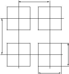
2.4Panel Cutout Dimensions
Unit : mm
125 Min.
145 Min.
92 +00.8
92+00.8
Fig. 2.3
IM 12B11A01-01E |
2-3 |
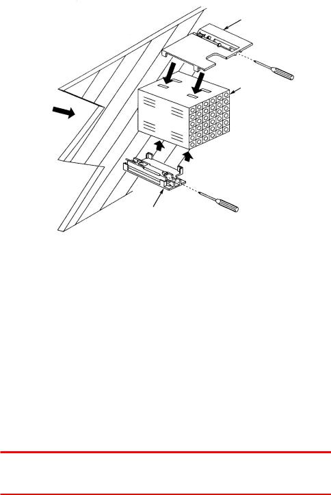
2.5Mounting
Large brackct (mount at top)
Panel
Terminal board
Insert from this
Side of panel
Insert driver as shown to tighten bracket
Small bracket (mount at bottom)
Fig. 2.4
Procedure 1
Cut out panel to mount instrument, cut out dimensions are shown on previous page.
Procedure 2
Insert rear of instrument (terminal block side) in panel cutout.
Procedure 3
Mount top and bottom brackets (see figure) to fix instrument to panel. *When detector output is to be prewired, refer to Sec. 3.4(2)
 WARNING
If instrument is a tight fit in cutout, do not force it as case or mounting brackets may be damaged.
2-4 |
IM 12B11A01-01E |
2. Preparation for Operation
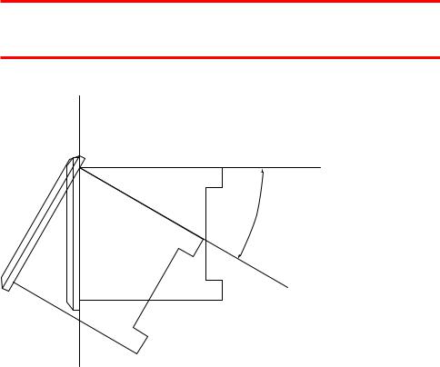
 WARNING
The instrument may be installed with the rear inclined at an angle up to 308 below front. Do not incline with front below rear.
8 30 to Up
F2.5.EPS
Fig. 2.5
IM 12B11A01-01E |
2-5 |
2-6 |
IM 12B11A01-01E |

3. Wiring
3.Wiring
This section explains wiring of the EXA PH100 pH converter.
 WARNING
Be sure to turn off power supply, and check with a tester or the like that connected cables do not have dangerous voltages applied. Do not touch terminals if power may be applied.
The recommended specifications for wiring terminals are shown below.
Use crimp-on terminals, designed to fit an ISO M3.5 screw, with an insulating sleeve.
|
|
|
|
|
|
3.7mm\ |
|
|
|
|
|
|
|
|
|
|
|
|
|
|
|
|
|
|
|
|
|
|
|
|
|
|
|
|
|
|
|
|
|
|
|
|
|
|
|
|
||||
|
Up to 7mm |
|
|
|
|
|
Up to 7mm |
|
|
3.7mm |
|
|
|
|
||
|
|
|
|
|
|
|
|
|
||||||||
|
|
|
|
|
|
|
|
|
|
|||||||
|
|
|
|
|
|
|
|
|
|
|||||||
|
|
|
|
|
|
|
|
F3.1.EPS |
||||||||
|
|
|
|
|
|
|
|
|
|
|
|
|
|
|
||
|
|
|
|
|
|
|
|
|
|
|
|
|
|
|
||
|
|
|
|
|
|
|
|
|
|
|
|
|
|
|
||
Fig. 3.1 |
|
|
|
|
|
|
|
|
|
|
|
|||||
dRecommended terminals |
|
|
|
|
|
|
|
|
|
|||||||
Table 3.1 |
|
|
|
|
|
|
|
|
|
|
|
|||||
|
|
|
|
|
|
|
|
|
|
|
||||||
|
|
|
Maker |
model |
|
For wire size: |
|
|
Tightening torque |
|
||||||
|
|
Japan AMP Co., Ltd |
1.25-YS3A |
|
0.3~1.65mm |
|
0.8N . m (8 kgf . cm) Up to or Iess |
|
||||||||
|
|
JST Co., Ltd |
YD1.25-3.5 |
|
|
|
||||||||||
|
|
|
|
|
|
|
|
|
|
|
|
|||||
T3.1.EPS
IM 12B11A01-01E |
3-1 |
3.1Pulling in Wiring
When wiring cables to terminals on the rear of the instrument, pull the cables into the instrument in the direction shown in Fig. 3.2
 CAUTION
There’s a terminal wiring diagram on the instrument nameplate on the side of the instrument.
Pull in cable from left side |
|
|
|
Terminal name |
|
|
Terminal name |
S1(NC) |
1 |
11 |
|
S1(NO) |
2 |
12 |
GE |
COM1 |
3 |
13 |
S |
S2 |
4 |
14 |
RE |
S3 |
5 |
15 |
RES |
S4 |
6 |
16 |
SE |
COM2 |
7 |
17 |
T1 |
L |
8 |
18 |
T2 |
N |
9 |
19 |
mA (1) |
|
10 |
20 |
mA (2) |
|
pH sensor Analog output |
||
Power |
cable |
cable |
|
Ground |
|
||
wiring |
wire |
|
|
Converter rear panel |
|||
|
|||
F3.2.EPS
Fig. 3.2 Direction to pull in wiring
3-2 |
IM 12B11A01-01E |
3. Wiring
3.2Noise prevention
dNoise sources
The following are typical sources of electrical noise
*Relays and contacts
*Solenoid coil, solenoid valve
*Power lines
*Inductive loads
*Inverters
*Motor commutators
*SCRs used for phase-angle control
*Wireless transmitters
*Welding equipment
*High-voltage ignition systems
dNoise prevention
When wiring, take the following precautions to minimize the effects of noise:
*Keep input circuit wiring as far as possible from power or ground wiring.
*Shielded wires, with single-point grounding, are effective for minimizing pickup of static electric fields.
*Twisted pair wire is effective in minimizing inductive noise pickup.
IM 12B11A01-01E |
3-3 |
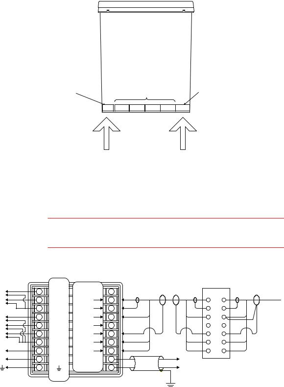
3.3Wiring Terminal Diagram
There are wiring terminals on the rear of the PH100 converter. Wire to terminals 1 to 10 and terminals 11 to 20 as shown in Fig. 3.3. The terminal block cannot be removed.
Row of terminals numbered 1 to 10 from top to bottom
Row of terminals numbered 11 to 20 from top to bottom
Not used
1-10 51-61 41-50 31-40 21-30 11-20
PH100 Top view
F3.3.EPS
Contact output and power wiring |
pH sensor and Analog output cable |
Fig. 3.3 Cable wiring position
(1) When intermediate terminal box is used
 CAUTION
Terminal size is ISO M3.5. There’s a terminal wiring diagram on the instrument nameplate on the side of the instrument.
Converter Rear View
|
|
|
|
Terminal |
|
|
Extension cable |
Terminal box |
|
|
|
|
|
|
WTB100-PH *1) |
||
Contact |
|
|
name |
Terminal |
|
WF100-PH *2) |
||
|
1 |
11 |
|
|||||
output 1(NC) |
S1(NC) |
name |
|
pH sensor |
||||
Contact |
|
2 |
S1(NO) |
GE |
12 |
|
||
|
|
GE |
||||||
output 1(NO) |
3 |
COM1 |
S |
13 |
|
S |
||
|
|
|
|
|||||
|
Contact |
4 |
S2 |
RE |
14 |
|
RE |
|
|
output 2 |
|
||||||
|
|
|
|
|
|
|
||
*3) |
Contact |
5 |
S3 |
RES |
15 |
|
RES |
|
|
output 3 |
6 |
S4 |
SE |
16 |
|
SE |
|
*3) |
Contact |
|
||||||
|
output 4 |
7 |
COM2 |
T1 |
17 |
|
T1 |
|
|
|
|
|
|||||
Power |
L |
8 |
L |
T2 |
18 |
|
T2 |
|
N |
9 |
N |
mA(1) |
19 |
|
|
||
supply |
Output signal |
|||||||
|
|
|
10 |
|
mA(2) |
20 |
||
|
|
|
|
|
|
|||
Ground to earth |
|
|
|
Shield |
|
|
||
|
|
|
|
|
|
|||
(grounding resistance |
|
|
|
|
Ground to earth (grounding resistance 100V or less) |
|||
|
100V or less) |
|
|
|
|
|||
|
|
|
|
|
|
|
||
|
|
Note : Terminal numbers are indicated on the label side of the converter. |
|
|
||||
|
|
|
|
|
|
|
|
F3.4E.EPS |
Fig. 3.4 Wiring diagram when intermediate terminal box is used
3-4
IM 12B11A01-01E
 Loading...