


 Loading...
User's
Manual
Plant Resource Manager
Reference
IM 33Y05Q10-11E
IM 33Y05Q10-11E
7th Edition

i
Introduction
This manual consists of the following parts:
•Part A: About PRM
This part provides general information about PRM.
•Part B: Configuring PRM
This part describes the tools and settings for configuring PRM.
•Part C: Working with the PRM Client
This part describes the basic features and operations of the PRM Client.
•Part D: Managing devices
This part describes device-related management tasks in PRM.
•Part E: Monitoring and diagnosing devices
This part describes device monitoring, diagnosing, and maintenance-related tasks in PRM.
•Part F: Configuring device parameters
This part describes device parameter configuration tasks in PRM.
•Part G: Maintaining PRM
This part describes how to maintain the PRM system using the backup tools and the Database Maintenance Tool.
•Part H: Performing an advanced diagnosis
This part describes concepts and procedures on how to perform an advanced diagnosis using the PRM Advanced Diagnostic Application (PAA).
•Part I: Working with the PST Scheduler
This part describes how to configure the PST Scheduler and then use it to schedule, perform, and monitor partial stroke tests.
•Part J: Connecting PRM to a CMMS
This part describes about CMMS, and the settings required to connect PRM to a CMMS.
•Part K: Integrating a third-party system
This part describes the procedures to integrate PRM with a third-party system.
Media No. IM 33Y05Q10-11E (CD) |
7th Edition : Feb. 2012 (YK) |
IM 33Y05Q10-11E |
7th Edition : Feb.08,2012-00 |
All Rights Reserved Copyright © 2006-2012, Yokogawa Electric Corporation |
|
|
|

ii
Plant Resource Manager Document Map
n Reference
n Security Guide
n Installation
n PRM Advanced Diagnostic Application
IM 33Y05Q10-11E 7th Edition : Feb.08,2012-00

iii
Safety precautions
nSafety, protection, and modification of the product
•To protect the system controlled by the product and the product itself and ensure safe operation, observe the safety precautions described in this user's manual . Yokogawa Electric Corporation (hereinafter referred to as YOKOGAWA) assumes no liability for safety if users fail to observe the safety precautions and instructions when operating the product.
•If this product is used in a manner not specified in this user's manual, the protection provided by this product may be impaired.
•If any protection or safety circuit is required for the system controlled by the product or for the product itself, install it externally.
•Use only spare parts that are approved by YOKOGAWA when replacing parts or consumables of the product.
•Do not use the product and accessories of the product such as power cords on devices that are not approved by YOKOGAWA. Do not use the product and its accessories for other purposes.
•Modification of the product is strictly prohibited.
•The following symbols are used in the product and user's manual to indicate the accompanying safety precautions:
Indicates that caution is required for operation. This symbol is placed on the product to refer the user to the user's manual to protect the operator and the equipment. In the user's manual, you will find precautions to avoid physical injury and/or death, which may be caused by accidents, such as electrical shocks resulting from operation mistakes.
Identifies a protective grounding terminal. Before using the product, ground the terminal.
Identifies a functional grounding terminal.
Indicates an AC supply.
Indicates a DC supply.
Indicates that the power supply switch is ON.
Indicates that the power supply switch is OFF.
nNotes on handling user's manuals
•Hand over the user's manuals to your end users so that they can keep the user's manuals on hand for reference.
•Read and understand the information in the user's manual thoroughly before using the product.
•For the avoidance of any doubt, the purpose of these user's manuals is not to warrant that the product is suitable for any particular purpose but to describe the functional details of the product.
•YOKOGAWA reserves the right to make improvements in the user's manuals and product at any time, without notice or obligation.
•Every effort has been made in the preparation of this manual to ensure the accuracy of its contents. However, should you have any questions or find any errors, contact our sales
IM 33Y05Q10-11E 7th Edition : Feb.08,2012-00

iv
representative or your local distributor. Manuals with incorrectly ordered pages or missing pages will be replaced.
nWarning and disclaimer
•The product is provided on an "as is" basis.
•YOKOGAWA shall have neither liability nor responsibility to any person or entity with respect to any direct or indirect loss or damage arising from using the product or any defect of the product that YOKOGAWA can not predict in advance.
nNotes on software
•YOKOGAWA makes no warranties, either expressed or implied, with respect to the software’s merchantability or suitability for any particular purpose, except as strictly provided in the terms of warranty.
•The software may be used only on the specified computer. If you need to use the software on another computer, you must purchase another software.
•It is strictly prohibited and an infringement of YOKOGAWA's Intellectual Property rights to reproduce the software except for the purpose of backup.
•Store all the original media that comes with the product in a safe place.
•It is strictly prohibited and an infringement of YOKOGAWA's Intellectual Property rights to reverse engineer, reverse compile, reverse assemble, or reduce the software to humanreadable form.
•No part of the software may be transferred, converted, or sublet for use by any third-party, without prior written consent from YOKOGAWA, failing which any warranty statements provided for the product and/or software shall be rendered void.
IM 33Y05Q10-11E 7th Edition : Feb.08,2012-00

v
Documentation conventions
n Symbol marks
The following symbols identify various sections of text in this user's manual.
Identifies instructions that must be observed to avoid physical injury, electric shock, or death.
Identifies instructions that must be observed to prevent damages to the software or hardware, or defects to the system.
Identifies important information required to understand operations or functions.
Identifies additional information.
Identifies referenced content.
You can view the referenced content by clicking the green text.
This action does not apply to the black text.
n Typographical conventions
The following typographical conventions are used throughout the user's manuals.
•Commonly used conventions throughout user's manuals
•Character string to be entered
The characters that must be entered are shown in monospace font as follows:
Example:
FIC100.SV=50.0
"∆" mark indicates a space between character strings that must be entered.
Example:
AL∆PIC010∆-SC
• Character string enclosed by brackets ({ })
Indicates an option that can be omitted.
Example:
.PR∆TAG{∆.sheet name}
•Conventions used to show key or button operations
Characters enclosed by brackets ([ ])
In descriptions of key or button operations, words enclosed in brackets indicate either a key on the HIS (Human Interface Station) keyboard, a key on the operation keyboard, a button name in a window, or an item on a list box displayed in a window.
Example:
To alter the function, press the [ESC] key.
IM 33Y05Q10-11E 7th Edition : Feb.08,2012-00

vi
•Conventions used in command syntax or program statements
The following conventions are used within a command syntax or program statement format.
•Characters enclosed by angle-brackets
Indicate character strings that user can specify freely according to certain guidelines.
Example:
#define <Identifier><Character string>
"..." mark
Indicates that the previous command or argument may be repeated
Example:
Imax (arg1, arg2, ...)
•Characters enclosed by brackets ([ ])
Indicate those character strings that can be omitted.
Example:
sysalarm format_string[output_value ...]
•Characters enclosed by separators (| |)
Indicate those character strings that can be selected from more than one option.
Example:
opeguide |
<format_character_string> [, <output_value> ...] |
|
OG,<element number> |
n Drawing conventions
Some drawings may be partially emphasized, simplified, or omitted for the convenience of description.
In the user's manual, the parts in some drawings may be placed in different positions or have different font settings. Note that some of the images in user's manuals are display examples.
IM 33Y05Q10-11E 7th Edition : Feb.08,2012-00

vii
Copyright and trademark notices
n All rights reserved
The copyright of the programs and online manuals contained in the software media shall remain with YOKOGAWA.
You are allowed to print the required pages of the online manuals for the purposes of using and/or operating the product. However, you are not allowed to print or reproduce the entire document. You can purchase the printed manual from YOKOGAWA.
Except as stated above, no part of the online manual may be reproduced, either in electronic or written form, registered, recorded, transferred, sold, or distributed (in any manner including without limitation, in the forms of paper documents, electronic media, films, or transmission via the network). Any in-action and/or silence by YOKOGAWA with regard to any breach of the above shall not be taken as any waiver of its rights whatsoever and YOKOGAWA reserves all its rights until expressly waived by written notification and no other occasions.
nTrademark acknowledgments
•PRM is a registered trademark of Yokogawa Electric Corporation in the United States and Japan.
•CENTUM, Vnet/IP, and ProSafe are registered trademarks of YOKOGAWA.
•STARDOM is a trademark.
•Microsoft, Windows, Windows Vista, Visual Basic, Visual C++, and Visual Studio are either registered trademarks or trademarks of Microsoft Corporation in the United States and/or other countries.
•Pentium is a registered trademark of Intel Corporation.
•Adobe and Acrobat are either registered trademarks or trademarks of Adobe Systems Incorporated in the United States and/or other countries.
•Oracle is a registered trademark of ORACLE Corporation.
•Maximo is a registered trademark of IBM.
•System 1, Bently Nevada, and Trendmaster are trademarks of General Electric Company.
•Ethernet is a registered trademark of XEROX Corporation.
•Java is a registered trademark of Sun Microsystems,Inc.
•


 in
in 


 fieldbus is a registered trademark of Fieldbus Foundation.
•HART is a registered trademark of HART Communication Foundation.
•All other company and product names mentioned in this manual are trademarks or registered trademarks of their respective companies.
•TM or ® mark are not used to indicate trademarks or registered trademarks in this manual.
•We do not use logos and logo marks in this manual.
IM 33Y05Q10-11E 7th Edition : Feb.08,2012-00

|
|
|
TocA-1 |
Plant Resource Manager Reference |
|
||
|
|
|
IM 33Y05Q10-11E 7th Edition |
|
|
||
CONTENTS |
|
||
PART-A |
About PRM....................................................... |
A-1 |
|
A1. |
The Plant Resource Manager............................................................ |
A1-1 |
|
A2. |
PRM packages.................................................................................... |
A2-1 |
|
A3. |
How PRM works................................................................................. |
A3-1 |
|
|
A3.1 |
Device connection methods..................................................................... |
A3-3 |
A4. |
Features.............................................................................................. |
A4-1 |
|
IM 33Y05Q10-11E 7th Edition : Feb.08,2012-00

|
|
|
|
TocB-1 |
Plant Resource Manager Reference |
|
|||
|
|
|
IM 33Y05Q10-11E 7th Edition |
|
|
|
|
||
CONTENTS |
|
|
||
PART-B |
Configuring PRM............................................. |
B-1 |
||
B1. Tasks after new installation.............................................................. |
B1-1 |
|||
B2. |
PRM Server......................................................................................... |
|
B2-1 |
|
|
B2.1 |
Server sets.................................................................................................. |
B2-3 |
|
B3. |
Field Communications Server.......................................................... |
B3-1 |
||
|
B3.1 |
Device path................................................................................................. |
B3-2 |
|
|
|
B3.1.1 |
Configuring device paths............................................................. |
B3-8 |
|
|
B3.1.2 Devices connected to CENTUM................................................ |
B3-16 |
|
|
|
B3.1.3 Devices connected to STARDOM.............................................. |
B3-22 |
|
|
|
B3.1.4 Devices connected to ProSafe-RS............................................ |
B3-25 |
|
|
|
B3.1.5 |
Devices connected locally.......................................................... |
B3-26 |
|
B3.2 |
FDT projects............................................................................................. |
B3-28 |
|
|
|
B3.2.1 |
Managing FDT projects.............................................................. |
B3-32 |
|
|
B3.2.2 |
Configuring FDT projects........................................................... |
B3-36 |
|
B3.3 |
DD files...................................................................................................... |
|
B3-51 |
|
|
B3.3.1 Installing DD files of other manufacturers.................................. |
B3-53 |
|
|
|
B3.3.2 |
DD Copy Tool............................................................................. |
B3-54 |
B4. |
PRM Client.......................................................................................... |
|
B4-1 |
|
|
B4.1 |
PRM Client connection settings............................................................... |
B4-2 |
|
|
B4.2 |
Customizing the appearance.................................................................... |
B4-5 |
|
|
B4.3 |
Label customization................................................................................... |
B4-6 |
|
|
B4.4 |
DTM Setup.................................................................................................. |
B4-7 |
|
|
B4.5 |
Copying DD files...................................................................................... |
B4-10 |
|
|
B4.6 |
Fast Device Patrol settings for HART devices...................................... |
B4-11 |
|
B5. Managing accounts and device security......................................... |
B5-1 |
|||
|
B5.1 |
Group and user accounts.......................................................................... |
B5-2 |
|
|
|
B5.1.1 |
PRM groups................................................................................. |
B5-3 |
|
|
B5.1.2 |
PRM user accounts...................................................................... |
B5-8 |
|
B5.2 |
Managing device security....................................................................... |
B5-15 |
|
|
|
B5.2.1 |
Configuring device security........................................................ |
B5-17 |
|
|
B5.2.2 Device security configuration examples..................................... |
B5-19 |
|
B6. |
Managing master data....................................................................... |
B6-1 |
||
IM 33Y05Q10-11E 7th Edition : Feb.08,2012-00
|
|
TocB-2 |
B6.1 |
Importing and exporting master data....................................................... |
B6-3 |
B6.2 |
Device icons............................................................................................... |
B6-5 |
|
B6.2.1 Device icon assignment............................................................... |
B6-9 |
IM 33Y05Q10-11E 7th Edition : Feb.08,2012-00

|
|
|
TocC-1 |
Plant Resource Manager Reference |
|
||
|
|
IM 33Y05Q10-11E 7th Edition |
|
|
|
|
|
CONTENTS |
|
|
|
PART-C |
Working with the PRM Client.......................... |
C-1 |
|
C1. Getting started with the PRM Client................................................. |
C1-1 |
||
C1.1 |
Accessing the PRM Client......................................................................... |
C1-2 |
|
C1.2 |
Using the PRM window.............................................................................. |
C1-4 |
|
|
C1.2.1 Using the Device Navigator......................................................... |
C1-6 |
|
|
C1.2.2 Using the function pane............................................................... |
C1-8 |
|
C1.3 |
Changing server sets in the PRM Client................................................ |
C1-13 |
|
C1.4 |
Using context search............................................................................... |
C1-14 |
|
C1.5 |
Viewing online manuals.......................................................................... |
C1-16 |
|
C2. Working with the Device Navigator.................................................. |
C2-1 |
||
C2.1 |
Plant view.................................................................................................... |
C2-2 |
|
|
C2.1.1 |
Plant view structure..................................................................... |
C2-3 |
|
C2.1.2 |
Plant view operations................................................................... |
C2-5 |
C2.2 |
Network view.............................................................................................. |
C2-8 |
|
|
C2.2.1 |
Network view structure................................................................ |
C2-9 |
|
C2.2.2 |
Network view operations............................................................ |
C2-14 |
C2.3 |
Class view................................................................................................. |
C2-19 |
|
|
C2.3.1 |
Class view structure................................................................... |
C2-20 |
|
C2.3.2 |
Class view operations................................................................ |
C2-23 |
C2.4 |
Custom view............................................................................................. |
C2-25 |
|
|
C2.4.1 |
Custom view structure............................................................... |
C2-26 |
|
C2.4.2 |
Custom view operations............................................................ |
C2-27 |
C3. Printing reports using the Self Document feature.......................... |
C3-1 |
||
C3.1 |
Printing reports.......................................................................................... |
C3-2 |
|
C3.2 |
Report structures....................................................................................... |
C3-9 |
|
C4. Searching using the Facility & Inspection Browser....................... |
C4-1 |
||
C4.1 |
Searching for information......................................................................... |
C4-4 |
|
C4.2 |
Searching for parameter data................................................................... |
C4-6 |
|
C4.3 |
Working with search results..................................................................... |
C4-9 |
|
IM 33Y05Q10-11E 7th Edition : Feb.08,2012-00

|
|
|
TocD-1 |
Plant Resource Manager Reference |
|
||
|
|
IM 33Y05Q10-11E 7th Edition |
|
|
|
|
|
CONTENTS |
|
|
|
PART-D |
Managing devices............................................ |
D-1 |
|
D1. Registering devices........................................................................... |
D1-1 |
||
D1.1 |
Device registration methods..................................................................... |
D1-2 |
|
D1.2 |
Device registration..................................................................................... |
D1-3 |
|
|
D1.2.1 |
Plug & Play.................................................................................. |
D1-4 |
|
D1.2.2 Host file set import....................................................................... |
D1-9 |
|
|
D1.2.3 |
Manual registration.................................................................... |
D1-12 |
|
D1.2.4 |
Maintenance information import................................................ |
D1-15 |
|
D1.2.5 |
FieldMate synchronization......................................................... |
D1-16 |
|
D1.2.6 Detecting HART devices connected to a multiplexer................. |
D1-17 |
|
D1.3 |
Replacing devices.................................................................................... |
D1-19 |
|
|
D1.3.1 Updating device information in PRM after replacing devices.............. |
D1-22 |
|
|
|
................................................................................................... |
|
|
D1.3.2 Device information inheritance function..................................... |
D1-23 |
|
D1.4 |
Updating device details........................................................................... |
D1-25 |
|
D1.5 |
Changing the network location of devices............................................ |
D1-27 |
|
D1.6 |
Deleting devices....................................................................................... |
D1-33 |
|
D2. Viewing and modifying device details............................................. |
D2-1 |
||
D2.1 |
Device tag display extension.................................................................... |
D2-2 |
|
|
D2.1.1 Device tag display extension for HART devices.......................... |
D2-3 |
|
|
D2.1.2 Device tag display extension for devices in STARDOM upstream |
||
|
|
projects........................................................................................ |
D2-4 |
|
D2.1.3 Configuring the device tag display extension in PRM.................. |
D2-5 |
|
|
D2.1.4 Device tag display extension specifications................................. |
D2-7 |
|
D2.2 |
Viewing the device list in the Device List window.................................. |
D2-9 |
|
D2.3 |
Viewing device details in the Device Details window........................... |
D2-11 |
|
D2.4 |
Modifying or updating devices............................................................... |
D2-17 |
|
D2.5 |
Exporting and importing the device list................................................. |
D2-18 |
|
D2.6 |
Customizing user-definable fields.......................................................... |
D2-22 |
|
D3. Validating HART device ranges........................................................ |
D3-1 |
||
D3.1 |
Validating HART device ranges................................................................ |
D3-3 |
|
|
D3.1.1 Acquiring CENTUM HART range information.............................. |
D3-4 |
|
|
D3.1.2 Acquiring PRM HART range information..................................... |
D3-6 |
|
IM 33Y05Q10-11E 7th Edition : Feb.08,2012-00

|
|
|
TocD-2 |
|
|
D3.1.3 Comparing HART range information............................................ |
D3-7 |
|
D3.2 |
HART device range validation procedure.............................................. |
D3-13 |
|
|
D3.2.1 Validation operation flow of HART device ranges...................... |
D3-14 |
|
|
D3.2.2 Acquiring CENTUM HART range information............................ |
D3-16 |
|
|
D3.2.3 Acquiring PRM range information.............................................. |
D3-17 |
|
|
D3.2.4 Acquiring HART range comparison result.................................. |
D3-18 |
|
D3.3 |
Handling errors........................................................................................ |
D3-19 |
D4. |
Using device templates..................................................................... |
D4-1 |
|
|
D4.1 |
Device classes............................................................................................ |
D4-2 |
|
D4.2 |
Registering devices during plant commissioning.................................. |
D4-3 |
|
|
D4.2.1 Using device templates................................................................ |
D4-4 |
|
|
D4.2.2 Without using device templates................................................... |
D4-6 |
|
D4.3 |
Device template contents.......................................................................... |
D4-8 |
|
D4.4 |
When to apply device templates............................................................... |
D4-9 |
|
D4.5 |
Working with device templates............................................................... |
D4-14 |
D5. |
Managing parts.................................................................................. |
D5-1 |
|
|
D5.1 |
Parts code................................................................................................... |
D5-2 |
|
D5.2 |
Parts list...................................................................................................... |
D5-5 |
D6. |
Managing document links................................................................. |
D6-1 |
|
|
D6.1 |
Registering documents in PRM................................................................ |
D6-2 |
|
D6.2 |
Using document links................................................................................ |
D6-5 |
D7. |
Importing and exporting maintenance information........................ |
D7-1 |
|
IM 33Y05Q10-11E 7th Edition : Feb.08,2012-00

|
|
|
TocE-1 |
Plant Resource Manager Reference |
|
||
|
|
IM 33Y05Q10-11E 7th Edition |
|
|
|
|
|
CONTENTS |
|
|
|
PART-E |
Monitoring and diagnosing devices.............. |
E-1 |
|
E1. Handling maintenance alarms.......................................................... |
E1-1 |
||
E1.1 |
Contents of maintenance alarms.............................................................. |
E1-5 |
|
E1.2 |
Configuring maintenance alarms............................................................. |
E1-8 |
|
|
E1.2.1 Configuring initial system settings.............................................. |
E1-10 |
|
|
E1.2.2 |
Device settings........................................................................... |
E1-15 |
|
E1.2.3 |
Alarm management rules........................................................... |
E1-17 |
|
E1.2.4 |
Notification rules........................................................................ |
E1-28 |
E1.3 |
Maintenance alarm messages................................................................. |
E1-36 |
|
E2. Using the Diagnosis window............................................................ |
E2-1 |
||
E2.1 |
Device status integration........................................................................... |
E2-5 |
|
E2.2 |
Configuring Status Override................................................................... |
E2-12 |
|
E3. Viewing the status of a device.......................................................... |
E3-1 |
||
E3.1 |
Device status icon...................................................................................... |
E3-2 |
|
|
E3.1.1 |
Status colors................................................................................ |
E3-3 |
|
E3.1.2 |
Status display............................................................................... |
E3-4 |
|
E3.1.3 |
Managing device status............................................................... |
E3-6 |
E3.2 |
Unacknowledged alarm icon..................................................................... |
E3-8 |
|
E3.3 |
Usage states............................................................................................. |
E3-10 |
|
E4. Diagnosing devices using DeviceViewer......................................... |
E4-1 |
||
E4.1 |
DeviceViewer window................................................................................ |
E4-3 |
|
|
E4.1.1 |
Periodic mode.............................................................................. |
E4-4 |
|
E4.1.2 |
Diagnostic Information tab........................................................... |
E4-5 |
|
E4.1.3 |
Trend Information tab................................................................... |
E4-8 |
E5. Working with maintenance marks.................................................... |
E5-1 |
||
E5.1 |
Managing MTMK definitions...................................................................... |
E5-6 |
|
E5.2 |
Configuring synchronization with CENTUM operation marks............. |
E5-11 |
|
|
E5.2.1 Configuring MTMK settings in the PRM Setup Tool................... |
E5-15 |
|
|
E5.2.2 Mapping CENTUM function blocks to PRM devices.................. |
E5-17 |
|
|
E5.2.3 Configuring device-level synchronization settings..................... |
E5-18 |
|
E5.3 |
Configuring MTMK-related notifications................................................ |
E5-19 |
|
E5.4 |
Setting and removing MTMKs in the PRM Client.................................. |
E5-20 |
|
IM 33Y05Q10-11E 7th Edition : Feb.08,2012-00

|
|
TocE-2 |
E5.5 |
Triggering synchronization in the Device Navigator............................ |
E5-24 |
E5.6 |
Examples of synchronization with CENTUM......................................... |
E5-25 |
|
E5.6.1 Example: Unidirectional synchronization initiated from CENTUM....... |
|
|
................................................................................................... |
E5-26 |
|
E5.6.2 Example: Bidirectional synchronization initiated from both PRM and |
|
|
CENTUM.................................................................................... |
E5-30 |
E6. Inspecting devices............................................................................. |
E6-1 |
|
E6.1 |
Managing service codes............................................................................ |
E6-3 |
E6.2 |
Managing inspection schedules............................................................... |
E6-6 |
E6.3 |
Managing inspection memos.................................................................. |
E6-11 |
E6.4 |
Reference codes....................................................................................... |
E6-21 |
E7. Working with history records........................................................... |
E7-1 |
|
E7.1 |
History window........................................................................................... |
E7-5 |
IM 33Y05Q10-11E 7th Edition : Feb.08,2012-00

|
|
|
TocF-1 |
Plant Resource Manager Reference |
|
||
|
|
IM 33Y05Q10-11E 7th Edition |
|
|
|
||
CONTENTS |
|
||
PART-F |
Configuring device parameters |
......................F-1 |
|
F1. |
Adjusting device parameters............................................................ |
F1-1 |
|
|
F1.1 |
Adjusting parameters................................................................................. |
F1-5 |
|
F1.2 |
Using Parameter Manager....................................................................... |
F1-16 |
|
F1.3 |
Using DTM Works..................................................................................... |
F1-27 |
|
F1.4 |
Using DD Menu for FF-H1 devices.......................................................... |
F1-36 |
|
F1.5 |
Connecting to FieldMate.......................................................................... |
F1-39 |
F2. |
Managing calibration data................................................................. |
F2-1 |
|
|
F2.1 |
Workflow for managing calibration data.................................................. |
F2-5 |
|
|
F2.1.1 Using a conventional device........................................................ |
F2-6 |
|
|
F2.1.2 Using a Documenting Calibrator.................................................. |
F2-9 |
|
F2.2 |
Working with calibration data................................................................. |
F2-13 |
|
F2.3 |
Viewing and modifying calibration data details.................................... |
F2-17 |
|
F2.4 |
Managing calibration groups.................................................................. |
F2-28 |
|
F2.5 |
Downloading and uploading calibration data........................................ |
F2-31 |
|
F2.6 |
Approving calibration data...................................................................... |
F2-34 |
|
F2.7 |
Printing documents related to calibration............................................. |
F2-37 |
|
F2.8 |
Exporting and importing of calibration data.......................................... |
F2-39 |
F3. |
Using PLUG-IN applications.............................................................. |
F3-1 |
|
|
F3.1 |
Working with PLUG-IN applications......................................................... |
F3-2 |
IM 33Y05Q10-11E 7th Edition : Feb.08,2012-00

|
|
TocG-1 |
Plant Resource Manager Reference |
|
|
|
|
IM 33Y05Q10-11E 7th Edition |
|
|
|
CONTENTS |
|
|
PART-G |
Maintaining PRM............................................. |
G-1 |
G1. Backing up and restoring PRM data................................................ |
G1-1 |
|
G1.1 |
Using the Fast Backup tool....................................................................... |
G1-2 |
G1.2 |
Using the PRM System Backup Script..................................................... |
G1-6 |
G2. Maintaining PRM databases............................................................. |
G2-1 |
|
G2.1 |
Archiving, retrieving, and deleting data.................................................. |
G2-5 |
|
G2.1.1 Procedures.................................................................................. |
G2-7 |
G2.2 |
Cleaning up the PRM database.............................................................. |
G2-13 |
G2.3 |
Cleaning up the Historian database....................................................... |
G2-15 |
IM 33Y05Q10-11E 7th Edition : Feb.08,2012-00

|
|
|
TocH-1 |
Plant Resource Manager Reference |
|
||
|
|
IM 33Y05Q10-11E 7th Edition |
|
|
|
||
CONTENTS |
|
||
PART-H |
Performing an advanced diagnosis............... |
H-1 |
|
H1. |
Advanced diagnosis.......................................................................... |
H1-1 |
|
|
H1.1 |
Software packages..................................................................................... |
H1-2 |
|
H1.2 |
How it works............................................................................................... |
H1-4 |
|
H1.3 |
Data acquisition......................................................................................... |
H1-9 |
|
H1.4 |
Device Diagnosis Data Historian............................................................ |
H1-12 |
|
H1.5 |
Replacing, renaming, and deleting devices.......................................... |
H1-14 |
H2. Preparing for an advanced diagnosis.............................................. |
H2-1 |
||
|
H2.1 |
Deciding on the system configuration..................................................... |
H2-2 |
|
H2.2 |
Configuration settings............................................................................... |
H2-4 |
|
H2.3 |
Acquiring and storing device diagnostic parameters............................ |
H2-6 |
H3. |
Starting the advanced diagnosis using the Diagnosis Navigator......... |
||
|
............................................................................................................. |
|
H3-1 |
|
H3.1 |
Opening and closing Diagnosis Navigator.............................................. |
H3-3 |
|
H3.2 |
Managing PAAs.......................................................................................... |
H3-6 |
|
H3.3 |
Managing diagnosis modules................................................................... |
H3-9 |
|
H3.4 |
Monitoring diagnosis modules............................................................... |
H3-17 |
|
H3.5 |
Importing and exporting diagnosis module information..................... |
H3-20 |
H4. Monitoring an advanced diagnosis.................................................. |
H4-1 |
||
H5. Displaying graphical results using the General-purpose Diagnostic |
|||
|
Tool...................................................................................................... |
|
H5-1 |
|
H5.1 |
Using GDT................................................................................................... |
H5-3 |
|
H5.2 |
Trend graphs............................................................................................ |
H5-10 |
|
H5.3 |
Correlation graphs................................................................................... |
H5-13 |
|
H5.4 |
Exporting data.......................................................................................... |
H5-16 |
IM 33Y05Q10-11E 7th Edition : Feb.08,2012-00

|
|
|
|
TocI-1 |
Plant Resource Manager Reference |
|
|||
|
|
|
IM 33Y05Q10-11E 7th Edition |
|
|
|
|
||
CONTENTS |
|
|
||
PART-I |
|
Working with the PST Scheduler..................... |
I-1 |
|
I1. |
About the PST Scheduler................................................................... |
I1-1 |
||
I2. |
Getting started with the PST Scheduler Client................................. |
I2-1 |
||
I3. |
Configuring the PST Scheduler......................................................... |
I3-1 |
||
|
I3.1 |
Managing users........................................................................................... |
I3-2 |
|
|
|
I3.1.1 |
Managing user roles...................................................................... |
I3-4 |
|
|
I3.1.2 |
Managing user teams.................................................................... |
I3-7 |
|
|
I3.1.3 |
Managing user accounts............................................................... |
I3-9 |
|
I3.2 |
Managing devices and groups................................................................. |
I3-12 |
|
|
|
I3.2.1 |
Importing device information....................................................... |
I3-14 |
|
|
I3.2.2 |
Managing PST groups................................................................. |
I3-19 |
|
|
I3.2.3 |
Managing hierarchy..................................................................... |
I3-26 |
|
I3.3 |
Configuring alarm and notification rules................................................ |
I3-28 |
|
|
I3.4 |
Customizing the PST Scheduler Client interface................................... |
I3-30 |
|
I4. |
Operating the PST Scheduler............................................................. |
I4-1 |
||
|
I4.1 |
Scheduling a PST........................................................................................ |
I4-2 |
|
|
I4.2 |
Manually performing PSTs........................................................................ |
I4-12 |
|
|
I4.3 |
Registering test results and assigning PST schedules......................... |
I4-15 |
|
I5. |
Monitoring PSTs.................................................................................. |
I5-1 |
||
|
I5.1 |
Viewing PST schedules and status............................................................ |
I5-2 |
|
|
I5.2 |
Viewing group and device details............................................................ |
I5-11 |
|
I6. |
Backing up and restoring PST Scheduler data................................ |
I6-1 |
||
|
I6.1 |
Backing up PST Scheduler data................................................................. |
I6-2 |
|
|
I6.2 |
Restoring PST Scheduler data................................................................... |
I6-4 |
|
IM 33Y05Q10-11E 7th Edition : Feb.08,2012-00
|
|
TocJ-1 |
Plant Resource Manager Reference |
|
|
|
|
IM 33Y05Q10 - 11E 7th Edition |
|
|
|
CONTENTS |
|
|
PART-J |
Connecting PRM to a CMMS........................... |
J-1 |
J1. About CMMS |
J1-1 |
|
J2. Connecting PRM ..............................................................to Maximo |
J2-1 |
|
J2.1 Configuring ...................................................................PRM and Maximo |
J2-2 |
|
|
J2.1.1 .......................................................................... |
J2-3 |
|
J2.1.2 ...................................................................... |
J2-6 |
|
J2.1.3 .....Synchronizing hierarchical structure and device information |
J2-14 |
|
J2.1.4 ................................................................ |
J2-20 |
|
J2.1.5 ......................Device management after connecting to Maximo |
J2-22 |
IM 33Y05Q10-11E 7th Edition : Feb.08,2012-00

|
|
TocK-1 |
Plant Resource Manager Reference |
|
|
|
IM 33Y05Q10-11E 7th Edition |
|
|
|
|
CONTENTS |
|
|
PART-K Integrating a third-party system |
.....................K-1 |
|
K1. PRM and System 1 integration......................................................... |
K1-1 |
|
K1.1 |
How it works............................................................................................... |
K1-6 |
K1.2 |
Requirements............................................................................................. |
K1-7 |
K1.3 |
Engineering procedure to connect System 1........................................ |
K1-10 |
IM 33Y05Q10-11E 7th Edition : Feb.08,2012-00

|
|
TocApp.-1 |
Plant Resource Manager Reference |
|
|
|
IM 33Y05Q10-11E 7th Edition |
|
|
|
|
CONTENTS |
|
|
Appendix |
|
|
Appendix 1. |
Help codes....................................................................... |
App.1-1 |
Appendix 2. |
Error codes...................................................................... |
App.2-1 |
Appendix 3. History messages stored in the PRM database........... |
App.3-1 |
|
Appendix 4. |
Glossary........................................................................... |
App.4-1 |
IM 33Y05Q10-11E 7th Edition : Feb.08,2012-00

<A. About PRM> |
A-1 |
A.About PRM
This part provides general information about PRM.
n Overview
This part consists of the following sections:
•The Plant Resource Manager Briefly describes PRM.
•PRM packages
Identifies the basic and optional packages.
•How PRM works
Describes how PRM works and identifies the supported device communication types and connection methods.
•Features
Describes the key PRM features and explains their availability.
IM 33Y05Q10-11E 7th Edition : Feb.08,2012-00

<A1. The Plant Resource Manager> |
A1-1 |
A1. The Plant Resource Manager
Plant Resource Manager (PRM), a key component of the YOKOGAWA VigilantPlant Asset Excellence initiative, is a centralized asset management system that helps to reduce plant downtime and maintenance costs.
PRM enables you to:
•Manage device information within the plant
•Monitor device status and alarms
•Manage device inspection activities
•Configure device parameters and settings
•Manage calibration information
•Perform advanced diagnostic analysis
PRM can be configured to manage assets used for a variety of systems within a plant, including:
•CENTUM
•ProSafe-RS
•STARDOM
PRM can also connect to the following systems and applications from third-party vendors to expand its asset maintenance management coverage:
•IBM Maximo Asset Management
•GE Energy's System 1
•PLUG-IN applications from device vendors
IM 33Y05Q10-11E 7th Edition : Feb.08,2012-00

<A2. PRM packages> |
A2-1 |
A2. PRM packages
PRM includes basic and optional packages. Each package requires a license.
n Basic packages
A PRM installation requires the following basic packages:
•PRM Server
The PRM Server collects device information and saves it to the database. This information includes messages, device parameters, inspection data, and other related information used in device management.
•PRM Client
PRM Client is a graphical user interface application used to view device information, monitor device status, and perform various operations related to device management.
•Field Communications Server
The Field Communications Server acts as the gateway between PRM and apparatuses to which devices are connected. The following are examples of apparatuses:
•CENTUM Field Control Station (FCS)
•ProSafe-RS Safety Control Station (SCS)
•STARDOM Field Control Node (FCN)
•STARDOM Field Control Junction (FCJ)
•HART multiplexer
PRM can connect to multiple apparatuses simultaneously. To establish the connection, the apparatus and the computer on which the Field Communications Server is installed must be on the same network. Multiplexers, on the other hand, must be connected directly to the COM port of the Field Communications Server computer.
n Optional packages
The following packages provide additional functionality to PRM:
•PRM Advanced Diagnostic Server
PRM Advanced Diagnostic Server enables you to perform advanced device diagnosis using algorithmic logic called PRM Advanced Diagnostic Applications (PAA). It comprises two major components, the Advanced Diagnosis and the Device Diagnosis Data Historian.
•PRM Advanced Diagnostic Application Development Kit
PRM Advanced Diagnostic Application Development Kit is used to develop or customize PRM Advanced Diagnostic Applications (PAA).
•Documenting Calibrator Interface
Documenting Calibrator Interface is used as an interface to documenting calibrators such as FLUKE.
•Interface for CMMS
The Interface for CMMS is used to connect PRM to a Computerized Maintenance Management System (CMMS).
IM 33Y05Q10-11E 7th Edition : Feb.08,2012-00

<A2. PRM packages> |
A2-2 |
•Interface for GE Energy's System 1
Interface for GE Energy's System 1 is used to connect PRM to GE Energy's System 1 and monitor the status of rotating machinery connected to System 1.
•PST Scheduler
PST Scheduler is used to schedule, conduct, and monitor partial stroke tests for emergency shutdown (ESD) valves.
IM 33Y05Q10-11E 7th Edition : Feb.08,2012-00

<A3. How PRM works> |
A3-1 |
A3. How PRM works
PRM provides a convenient way of obtaining the health condition of instrumentation equipment throughout the plant from a single location. PRM does this by periodically communicating with devices and displaying the device status represented by color-coded icons in the PRM Client. You can also initiate a request to obtain the device status in real time.
To communicate with devices, the Field Communications Server of PRM needs to be connected to the apparatuses to which field devices are connected. The following are examples of apparatuses:
•CENTUM Field Control Station (FCS)
•ProSafe-RS Safety Control Station (SCS)
•STARDOM Field Control Node (FCN)
•STARDOM Field Control Junction (FCJ)
•HART multiplexer
PRM can connect to multiple apparatuses simultaneously.
PRM works most effectively with smart devices such as flow meters, control valves, rotating machinery, among other devices commonly found in plants. These are devices that have the capability to communicate with PRM digitally. You can use information from smart devices to perform device diagnosis. You can also utilize advanced PRM capabilities for diagnostic analysis through the use of logical algorithms called PRM Advanced Diagnostic Application (PAA). However, you can also register static devices or other plant assets considered as important components in your plant processes. If there are alarms or abnormalities, you can use several tools in PRM to configure device parameters and settings remotely without going to the actual location of the device.
PRM can be customized to match the existing operations and procedures you conduct in your plant. For example, you can create rule sets to define how alarms and messages will be processed. This gives you the capability to add necessary information about the issue, cause, or recommended action in the message so that the intended recipient understands clearly how to handle the message. You can also define notification rules to determine if PRM should block or relay the information to an engineer or another computer station in the network.
IM 33Y05Q10-11E 7th Edition : Feb.08,2012-00

|
|
|
|
|
|
|
<A3. How PRM works> |
A3-2 |
|||||
SMTP Server |
|
|
|
|
|
|
|
|
|
||||
Basic PRM system |
|
|
|
|
|
|
|
||||||
(E-mail Server) |
|
|
|
|
|
|
|
||||||
|
|
|
|
|
|
|
|
|
|
|
|
|
|
|
|
|
|
|
|
|
|
|
|
Device status |
|
|
|
|
|
|
|
|
|
|
|
|
|||||
|
|
|
|
|
|
|
|
|
|
display |
|
|
|
|
|
|
|
|
|
|
|
|
|||||
|
|
|
|
|
|
|
|
|
|
|
|
|
|
|
|
|
|
|
|
|
|
|
PRM Client |
|
|
||
|
|
|
|
|
PRM Server |
· Device management |
|
||||||
|
|
|
|
|
|
|
|
|
|
|
|||
|
|
|
|
notification |
|
· Audit trail |
|
|
|
|
|
|
|
|
|
|
|
|
|
|
|
|
|
|
|
||
|
|
Alarm |
Message |
PRM |
|
|
database |
||
HIS |
|
notification |
||
CAMS |
notification |
|
Saving maintenance |
|
|
for HIS |
|
|
alarm message |
|
- Alarm management |
|
|
|
- Basic diagnosis |
|
|
Operator guide |
|
|
|
notification |
Message and data |
|
|
OPC |
|
|
|
server Acquiring |
acquisition |
Manual |
|
alarm notification |
|
alarm input |
|
|
Acquiring device parameters |
Online device |
|
|
parameter adjustment |
||
HIS or other systems |
(device diagnosis information) |
|
|
Field Communications Server |
|
||
(System 1, OPC interface) |
|
||
|
Communication driver |
|
|
|
Hardware (Control bus, Communication port) |
|
|
|
Control bus, Field network |
Device |
|
|
|
parameter |
|
Field devices
GUID-A5C69D43-5993-4602-987A-53753DD51CD0-default-pdf.pdf
Figure A3-1 PRM in a plant
SEEALSO For more information about PRM installation and configuration procedures, refer to: Plant Resource Manager Installation (IM 33Y05Q12-11E)
IM 33Y05Q10-11E 7th Edition : Feb.08,2012-00
<A3.1 Device connection methods> |
A3-3 |
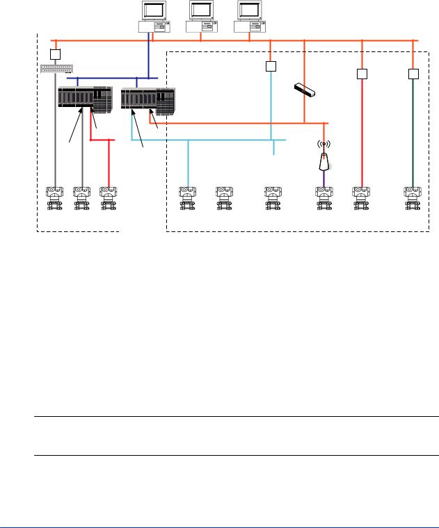
A3.1 Device connection methods
PRM can communicate with devices that use different communication types and connection methods. To connect to a particular device, you must either configure a device path or a Field Device Tool (FDT) project. The following diagram shows the connection methods that PRM supports and classifies them into these categories:
•Device path configuration
•FDT project configuration
Field |
PRM |
PRM |
Communications |
||
Server |
Server |
Client |
|
|
|
Ethernet |
|
RS-485/Ethernet |
|
|
|
|
converter |
Ethernet/ |
|
|
|
|
|
Other |
||
multiplexer |
PROFIBUS |
FF-H1/HSE |
||
converter |
FDT-compliant |
|||
V net |
linking device |
|||
|
|
communication |
||
|
|
Layer-3 |
devices |
|
|
|
|
||
|
|
switch |
|
|
|
|
Ethernet |
|
|
FF-H1 |
ALE111 |
|
|
|
I/O module |
PROFIBUS |
|
||
|
|
HART |
PROFIBUS |
|
|
|
|
|
|
Field |
I/O module |
I/O module |
PROFIBUS/ |
|
|
PROFIBUS |
|
|
Wireless |
|
|
|
|
|||||
|
|
HART |
|
|
DP/PA |
|
|
integrated |
|
|
converter |
|
coupler |
|
gateway |
||
|
|
|
|
|
|
|
|
|
|
|
|
|
|
|
|
|
|
HART |
HART |
FF-H1 |
PROFIBUS DP |
HART |
PROFIBUS PA |
ISA100 |
FF-H1 |
Other FDT- |
|
device |
device |
device |
device |
device |
|
device |
wireless device |
device |
compliant |
|
|
|
|
|
|
|
|
|
devices |
|
|
|
|
|
|
|
|||
Device path configuration |
|
|
|
FDT project configuration |
|
|
|||
GUID-75FFEA0F-3C37-4C11-B4DA-D301E0222992-default-pdf.pdf
Figure A3.1-1 Device connection methods
n Device path configuration
SEE
ALSO
A device path is a communication path to the location on the physical network to which a device is connected. You must configure device paths to enable PRM to communicate with the following devices:
•FF-H1 and HART devices connected to an I/O module on CENTUM or STARDOM
•HART devices connected to an I/O module on ProSafe-RS
•FF-H1 devices connected to the Field Communications Server through an NI-FBUS card
•HART devices connected to the Field Communications Server through a multiplexer or modem
For more information about configuring device paths, refer to:
B3.1, “Device path” on page B3-2
n FDT project configuration
A Field Device Tool (FDT) project defines a network topology comprising of communication, gateway, and device DTMs, and stores the configuration settings of all the DTMs in the topol-
IM 33Y05Q10-11E 7th Edition : Feb.08,2012-00
Loading...