


 Loading...
User's Manual PK200
CURRENT-TO-PNEUMATIC CONVERTER
[Style:S2]
IM 21B03D01-01E
IM 21B03D01-01E
12th Edition
|
|
|
|
CONTENTS |
|
|
|
|
CONTENTS |
|
|
|
|
|
|
|
|
|
INTRODUCTION.............................................................................................. |
|
iii |
||
1. |
HANDLING PRECAUTIONS ......................................................................... |
1-1 |
|
||
|
1.1 |
Checking the Model Suffix Code and Specifications .......................... |
1-1 |
|
|
|
1.2 |
Transportation Precautions ................................................................. |
1-1 |
|
|
|
1.3 |
Storage Precautions ............................................................................ |
1-2 |
|
|
|
1.4 |
Precautions for Installation Area ......................................................... |
1-2 |
|
|
|
1.5 |
Installation of Intrinsically Safe Type .................................................. |
1-2 |
|
|
|
|
1.5.1 CSA Intrinsically Safe Type ......................................................... |
1-2 |
|
|
|
|
1.5.2 TIIS Intrinsically Safe Type .......................................................... |
1-3 |
|
|
|
1.6 |
Installation of Flameproof Type .......................................................... |
1-3 |
|
|
|
|
1.6.1 |
TIIS Flameproof Type .................................................................. |
1-3 |
|
|
|
1.6.2 |
FM Explosionproof Type .............................................................. |
1-4 |
|
|
1.7 |
EMC Conformity Standard .................................................................. |
1-4 |
|
|
2. |
OVERVIEW .................................................................................................... |
|
|
2-1 |
|
|
2.1 |
Functional Description ......................................................................... |
2-1 |
|
|
|
2.2 |
Standard Specifications ...................................................................... |
2-1 |
|
|
|
2.3 |
Model and Suffix Codes ...................................................................... |
2-2 |
|
|
|
2.4 |
Options ................................................................................................ |
2-2 |
|
|
|
2.5 |
External Dimensions ........................................................................... |
2-3 |
|
|
|
2.6 |
Part Names ......................................................................................... |
2-4 |
|
|
3. |
INSTALLATION ............................................................................................. |
|
3-1 |
|
|
|
3.1 |
Overview ............................................................................................. |
3-1 |
|
|
|
3.2 |
Installation ........................................................................................... |
3-1 |
|
|
|
|
3.2.1 |
Pipe Mounting .............................................................................. |
3-1 |
|
|
|
3.2.2 |
Wall Mounting ............................................................................... |
3-1 |
|
4. |
WIRING AND PIPING ................................................................................... |
4-1 |
|
||
|
4.1 |
Piping .................................................................................................. |
4-1 |
|
|
|
|
4.1.1 |
Supply Air ..................................................................................... |
4-1 |
|
|
|
4.1.2 |
Air Supply Piping .......................................................................... |
4-1 |
|
|
|
4.1.3 |
Output Piping ................................................................................ |
4-1 |
|
|
4.2 |
General-Use and Flameproof Type Wiring ......................................... |
4-1 |
|
|
|
|
4.2.1 |
Cable Selection ............................................................................ |
4-1 |
|
|
|
4.2.2 |
Wiring ........................................................................................... |
4-2 |
|
|
|
4.2.3 |
Grounding ..................................................................................... |
4-4 |
|
|
4.3 |
Intrinsically Safe Type Wiring ............................................................. |
4-4 |
|
|
5. |
OPERATION .................................................................................................. |
|
|
5-1 |
|
|
5.1 |
Auto/Manual (A/M) Transfer Mechanism ............................................ |
5-1 |
|
|
|
5.2 |
Zero Point Adjustment ........................................................................ |
5-1 |
|
|
|
5.3 |
Calibration ........................................................................................... |
5-2 |
|
|
|
5.4 |
Range Adjustment ............................................................................... |
5-4 |
|
|
|
5.5 |
4 to 20mA/10 to 50mA Selection ........................................................ |
5-4 |
|
|
FD No. IM 21B03D01-01E |
i |
IM 21B03D01-01E |
12th Edition: Aug. 2012 (KP) |
|
|
All Rights Reserved, Copyright © 1992, Yokogawa Electric Corporation |
|
|
|
|
|
CONTENTS |
6. |
MAINTENANCE............................................................................................. |
6-1 |
|
|
6.1 |
Overview ............................................................................................. |
6-1 |
|
6.2 |
Periodic Inspection .............................................................................. |
6-1 |
|
|
6.2.1 Cleaning the Restrictor ................................................................. |
6-1 |
|
6.3 |
Parts Replacement .............................................................................. |
6-1 |
|
|
6.3.1 Replacing the Screen Filter .......................................................... |
6-1 |
|
|
6.3.2 Replacing the Controller Relay .................................................... |
6-2 |
|
|
6.3.3 Replacing the Amplifier Assembly ............................................... |
6-2 |
7. |
TROUBLESHOOTING................................................................................... |
7-1 |
|
|
7.1 |
Overview ............................................................................................. |
7-1 |
|
7.2 |
Operation Principle .............................................................................. |
7-1 |
|
7.3 |
Troubleshooting Flow .......................................................................... |
7-2 |
Appendix A. AIR SUPPLY SYSTEM................................................................ |
A-1 |
||
INSTALLATION AND OPERATING PRECAUTIONS FOR TIIS INTRINSICALLY |
|||
|
SAFE EQUIPMENT ............................................................................. |
Ex-A03E |
|
INSTALLATION AND OPERATING PRECAUTIONS FOR TIIS FLAMEPROOF |
|||
|
EQUIPMENT ........................................................................................ |
|
Ex-B03E |
Customer Maintenance Parts List |
|
||
|
Model PK200 Current-to-Pneumatic Converter .............. |
CMPL 21B03D01-01E |
|
Revision Record
ii |
IM 21B03D01-01E |
INTRODUCTION
INTRODUCTION
Thank you for purchasing the Current-to-Pneumatic Converter.
The Current-to-Pneumatic Converter is correctly calibrated at the factory before shipment. To ensure correct and efficient use of the instrument, please read this manual thoroughly and fully understand how to operate the instrument before operating it.
■Regarding This Manual
•This manual should be passed on to the end user.
•The contents of this manual are subject to change without prior notice.
•All rights reserved. No part of this manual may be reproduced in any form without Yokogawa’s written permission.
•Yokogawa makes no warranty of any kind with regard to this manual, including, but not limited to, implied warranty of merchantability and fitness for a particular purpose.
•If any question arises or errors are found, or if any information is missing from this manual, please inform the nearest Yokogawa sales office.
•The specifications covered by this manual are limited to those for the standard type under the specified model number break-down and do not cover custom-made instrument.
•Please note that changes in the specifications, construction, or component parts of the instrument may not immediately be reflected in this manual at the time of change, provided that postponement of revisions will not cause difficulty to the user from a functional or performance standpoint.
■ Safety Precautions
•For the protection and safety of the operator and the instrument or the system including the instrument, please be sure to follow the instructions on safety described in this manual when handling this instrument. In case the instrument is handled in contradiction to these instructions, Yokogawa does not guarantee safety.
•Yokogawa will not be liable for malfunctions or damage resulting from any modification made to this instrument by the customer.
•For the intrinsically safe equipment and explosionproof equipment, in case the instrument is not restored to its original condition after any repair or modification undertaken by the customer, intrinsically safe construction or explosionproof construction is damaged and may cause dangerous condition. Please contact Yokogawa for any repair or modification required to the instrument.
•The following safety symbol marks are used in this Manual:
WARNING
Indicates a potentially hazardous situation which, if not avoided, could result in death or serious injury.
CAUTION
Indicates a potentially hazardous situation which, if not avoided, may result in minor or moderate injury. It may also be used to alert against unsafe practices.
IMPORTANT
Indicates that operating the hardware or software in this manner may damage it or lead to system failure.
NOTE
Draws attention to information essential for understanding the operation and features.
iii |
IM 21B03D01-01E |
INTRODUCTION
WARRANTY
•The warranty shall cover the period noted on the quotation presented to the purchaser at the time of purchase. Problems occurred during the warranty period shall basically be repaired free of charge.
•In case of problems, the customer should contact the Yokogawa representative from which the instrument was purchased, or the nearest Yokogawa office.
•If a problem arises with this instrument, please inform us of the nature of the problem and the circumstances under which it developed, including the model specification and serial number. Any diagrams, data and other information you can include in your communication will also be helpful.
•Responsible party for repair cost for the problems shall be determined by Yokogawa based on our investigation.
● The Purchaser shall bear the responsibility for repair costs, even during the warranty period, if the malfunction is due to:
•Improper and/or inadequate maintenance by the Purchaser.
•Failure or damage due to improper handling, use or storage which is out of design conditions.
•Use of the product in question in a location not conforming to the standards specified by the Yokogawa, or due to improper maintenance of the installation location.
•Failure or damage due to modification or repair by the party except Yokogawa or who is requested by Yokogawa.
•Malfunction or damage from improper relocation of the product in question after delivery.
•Reason of force majeure such as fires, earthquakes, storms/floods, thunder/lightening, or other natural disasters, or disturbances, riots, warfare, or radioactive contamination.
iv |
IM 21B03D01-01E |

1. HANDLING PRECAUTIONS
1.HANDLING PRECAUTIONS
IMPORTANT
For installation, wiring and maintenance in hazadous areas, please follow 1.5 Installation of Intrinsically Safe Type, 1.6 Installation of Flameproof Type and “Installation and Operating Precautions for TIIS Flameproof Equipment” at the end of this manual
The PK200 current-to-pneumatic converter is fully factory inspected before shipment. When the instrument is delivered, visually check the instrument and accessories to ensure that they are not damaged. This chapter describes the handling precautions, read them carefully before using the instrument.
For items other than those described in this chapter, see the relevant items.
If you wish to make inquiry, contact the distributor where you purchased the instrument or the nearest YOKOGAWA service station.
Figure 1.2 Data Plate for CSA Intrinsically Safe Type
Figure 1.3 Data Plate for FM Explosionproof Type
1.1Checking the Model Suffix Code and Specifications
The data plate on the side face of the instrument base shows the model suffix code and specifications. With reference to the model suffix code and specifications in section 2.3, confirm that the instrument is as specified by the order.
For inquiry, inform us of the model suffix code and instrument serial number.
1.2 Transportation Precautions
To prevent damage occurring during transportation, transport the converter in the original shipping container (box) with all packing items and equipment in its proper position.
Figure 1.1 Data Plate for General-Use Type
1-1 |
IM 21B03D01-01E |
1.3 Storage Precautions
(1) Select a storage place :
•Which is protected from rain and water.
•Which is free from vibration and impact.
•Whose temperature and humidity are as specified
below. Room temperature and humidity (approx. 25°C and 65%) are more recommendable.
Temperature: -10 to 60°C
Humidity: Less than 80%
(2)Store the converter in the packing condition of shipment from YOKOGAWA whenever possible.
1.4Precautions for Installation Area
To use the converter stably for a long time, determine an installation place, taking into account the following.
(1) Ambient Temperature
Avoid installing the instrument in a place subject to a large temperature gradient and variations. If the instrument is subject to plant-generated heat radiation, take measures such as provision of heat protection and good ventilation.
(2) Atmospheric Conditions
Avoid installing the converter in corrosive atmosphere. Should it be used in corrosive atmosphere, make provision for maintaining good ventilation.
(3) Magnetic Field
Please contact us in the case this instrument is installed the strong Magnetic Field.
1. HANDLING PRECAUTIONS
1.5Installation of Intrinsically Safe Type
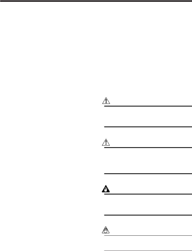
1.5.1 CSA Intrinsically Safe Type
[Intrinsically Safe]
Hazardous Location  Non-hazardous Location
|
|
|
General |
Class I, II, III, Division 1, |
|
|
Purpose |
Groups A, B, C, D, E, F, G |
Safety Barrier |
Equipment |
|
+ |
+ |
+ |
+ |
– |
– |
– |
– |
PK200 Current-to-
pneumatic Converter
[Nonincendive]
Hazardous Location  Non-hazardous Location
Class I, II, III, Division 2, |
General |
||||||||||
Groups A, B, C, D, E, F, G |
Purpose |
||||||||||
Class III, Division 1. |
Equipment |
||||||||||
|
|
|
|
|
|
|
|
|
|
|
|
|
+ |
|
|
|
|
|
|
||||
|
|
|
+ |
||||||||
|
|
|
|
|
|
|
|
|
|
||
|
|
|
– |
|
|
|
|
– |
|||
|
|
|
|
||||||||
|
|
|
|
|
|
|
|
|
|
|
|
|
|
|
|
|
|
|
|
|
|
|
|
|
|
|
|
|
|
|
|
|
|
|
|
|
|
|
|
|
|
|
|
|
|
|
|
PK200 Current-to-
pneumatic Converter
Note: Not use safety Barrier
F0105.EPS
Figure 1.4 Installation of CSA Intrinsically Safe Type
1.PK200 current to pneumatic converter is applicable for use in hazardous locations:
•Intrinsically Safe for Class I, Division 1, Groups A, B, C & D, Class II, Division 1, Groups E, F & G and Class III, Division 1 Hazardous Locations.
•Nonincendive for Class I, Division 2, Groups A, B, C & D, Class II, Division 2, Groups F & G, and Class III, Division 1 Hazardous Locations.
•Outdoor Hazardous Locations, Encl Type 4X.
•Temperature Class: T4
•Ambient Temperature: -40 to 60°C
2. Entity Parameters
•Intrinsically safe apparatus parameters Vmax = 30V
Imax = 165mA Pmax = 0.9W
Ci = 2nF
Li = 730 H
•Associated apparatus parameters (CSA Certified
Barriers)
Voc ≤ 30V Isc ≤ 165mA
Pmax ≤ 0.9W
1-2 |
IM 21B03D01-01E |
3. Installation
•Control equipment connected to barrier must not use or generate more than 250 Vrms or Vdc.
•The safety barrier must be CSA certified.
•Associated apparatus manufacturer’s installation drawing must be followed when installing this apparatus.
•The maximum power delivered from the barrier must not exceed 0.9 W.
•Note a warning label worded “SUBSTITUTION OF COMPONENTS MAY IMPAIR INTRINSIC SAFETY” and “INSTALL IN ACCORDANCE WITH DOC. NO. ICS006-A12 P.1 AND 2”.
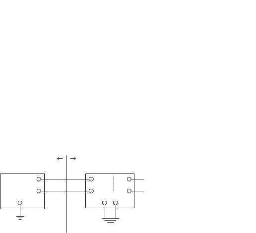
1.5.2 TIIS Intrinsically Safe Type
The model PK200/JS3 current-to-pneumatic converters, which have obtained certification according to technical criteria for explosion-protected construction of electric machinery and equipment (Standards Notification No.556 from the Japanese Ministry of Labor) conforming to IEC standards, is designed for hazardous areas where explosive gases and/or inflammable vapors may be present. (This allows installation in Division 0 , 1 and 2 areas)
To preserve the safety of flameproof equipment requires great care during mounting, wiring, and piping. Safety requirements also place restrictions on maintenance and repair activities. Users absolutely must read the following instructions and “Installation and Operating Precautions for TIIS Intrinsically Safe Equipment (EX - A03E)” at the end of this manual.
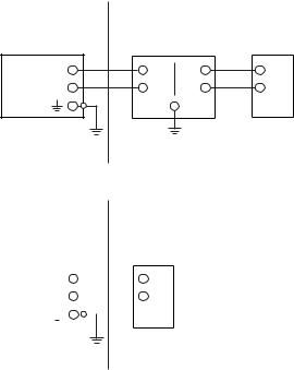
1. Installation
The PK200 Current-to-Pneumatic Converter should be used in connection with the certified safety barrier as shown below. All wiring shall comply with local installation requirements.
[Installation Diagram]
Hazardous Area |
Non-hazardous Area |
|
+ |
+ |
+ |
– |
– |
– |
PK200 Current-to-pneumatic |
Safety barrier |
Converter |
F0107.EPS |
|
1. HANDLING PRECAUTIONS
2. Temperature
Install the PK200, So that any part of the instrument that may exposed to the inflammable gas or vapor would not exceed the temperature 60°C
3. Safety Barrier
Use the certified safety barrier that satisfies the following requirements.
•Safety Ratings
Maximum output voltage: 28V or less Maximum output current: 94.3mA or less Maximum output power: 0.66W or less
•Protection type and group Protection type: ia Group: IIC
•Allowable inductance and capacitance Maximum_external inductance: More than the external wiring inductance
Maximum_external capacitance: More than the sum of the external wiring capacitance and 39nF
Table 1.1 Recommended Safety Barrier
Contact each supplier for the details of the barrier.
Supplier |
Type |
Model |
|
|
|
MTL |
Isolated type |
MTL5046 |
|
|
|
P+F |
Isolated type |
KFD2-SCD-Ex1.LK* |
|
|
|
T0101.EPS
*To connect this barrier with PK200 converter, for the connection between the barrier and the controller, use the terminal #7 and #9 of the barrier.
1.6Installation of Flameproof Type
1.6.1 TIIS Flameproof Type
The model PK200/JF3 current-to-pneumatic converters, which have obtained certification according to technical criteria for explosion-protected construction of electric machinery and equipment (Standards Notification No.556 from the Japanese Ministry of Labor) conforming to IEC standards, is designed for hazardous areas where explosive gases and/or inflammable vapors may be present. (This allows installation in Division 1 and 2 areas)
To preserve the safety of flameproof equipment requires great care during mounting, wiring, and piping. Safety requirements also place restrictions on maintenance and repair activities. Users absolutely must read “Installation and Operating Precautions for TIIS Flameproof Equipment (EX - B03E)” at the end of this manual.
1-3 |
IM 21B03D01-01E |

1.6.2 FM Explosionproof Type
Following items are described in the instruction documents of this instrument to ensure certified explosionproof properties.
1.PK200 Current to Pneumatic Converter is applicable for use in hazardous areas;
*Explosionproof for Class I, Division 1, Groups B, C and D.
*Dust ignitionproof for Class I/II, Division 1, Groups E, F and G.
*Outdoor hazardous locations, NEMA 4X.
2. Wiring
*All wiring shall comply with National Electrical Code ANSI/NEPA70 and Local Electrical Codes.
*When installed in Division 1, “FACTORY SEALED, CONDUIT SEAL NOT REQUIRED”. However, in case of installing a sealing fitting (option) for waterproof or other purposes, see 4.2.2(6).
3. Operation
* WARNING: OPEN CIRCUIT BEFORE REMOVING COVER.
FACTORY SEALED, CONDUIT SEAL NOT REQUIRED. INSTALL IN ACCORDANCE WITH THE INSTRUCTION MANUAL IM 21B3D1-01E
*Take care not to generate mechanical spark when access to the instrument and peripheral devices in hazardous location.
4. Maintenance and Repair
*The instrument modification or parts replacement by other than authorized representative of Yokogawa Electric Corporation is prohibited and will void Factory Mutual Explosionproof Certification.
1. HANDLING PRECAUTIONS
1.7 EMC Conformity Standard
EN61326-1 Class A, Table 2 (For use in industrial locations)
CAUTION
To meet EMC regulations, Yokogawa recommends that customers run signal wiring through metal conduits or use shielded twisted-pair cabling when installing this instrument in a plant.
CAUTION
This instrument is a Class A product, and it is designed for use in the industrial environment. Please use this instrument in the industrial environment only.
1-4 |
IM 21B03D01-01E |
2. OVERVIEW
2.OVERVIEW
2.1 Functional Description
The PK200 current-to-pneumatic converter is a signal converter that receives an electronic controller or DCS control signal and converts it into a pneumatic pressure signal.
2.2 Standard Specifications
Materials: |
Case: Aluminum die-cast |
|
Paint: Polyurethane resin-baked finish |
|
Paint color: Deep-sea moss-green |
|
(Munsell 0.6GY3.1/2.0 or equivalent) |
|
Pressure Gauge Case: Stainless steel |
|
JIS SUS304 |
Input Signals: |
4 to 20mA DC or 10 to 50mA DC |
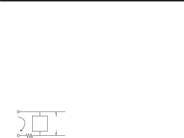
Input Resistance: PK200 is not a constant resistor. Equivalent circuit of PK200 is shown in Fig. 2.1
Input Signal |
Constant |
|
Voltage |
||
4 to 20mA DC |
||
Circuit |
||
|
||
|
50Ω MAX |
Fig. 2.1 Equivalent Circuit
5V DC
(8V DC for CENELEC Intrinsically safe type and TIIS Intrinsically safe type.)
F0201.EPS
Operating Voltage:
Input Signal |
Min. |
Max. |
|
|
|
|
|
4 to 20mA (except /JS3) |
5.2V |
(at 4mA) |
6.0V (at 20mA) |
|
|
|
|
4 to 20mA (for /JS3) |
8.2V |
(at 4mA) |
9.0V (at 20mA) |
|
|
|
|
10 to 50mA |
5.35V |
(at 10mA) |
6.75V (at 50mA) |
|
|
|
|
T0200.EPS
I/O Action: |
Output pressure increases as input |
|
increases. |
Manual Operation: Available using auto/manual (A/M) transfer switch (Optional)
Zero Point Adjusting Range: Within 0 to ±10% of span Span Adjusting Range: Within 100 to 125% of span Air Consumption: 4Nl/min maximum (for a supply air
pressure of 140kPa)
Max. Air Delivery: 110Nl/min maximum (for a supply air pressure of 140kPa)
Minimum Load Capacity:
1m copper tube with 4mm I.D. +20cc Ambient Temperature:
-40 to 80°C (for general use)
-20 to 60°C (TIIS Explosionproof , TIIS Intrinsically safe type)
-40 to 60°C (for FM Explosionproof, CSA Intrinsically safe type)
Water Proof Construction: IEC IP54
NEMA type 4X Intrinsically Safe Construction:
CSA Intrinsically Safe (/CS1) : Intrinsically Safe for Class I, Division 1, Groups A, B, C
&D Class II, Division 1, Groups E, F
&G and Class III, Division 1 Hazardous Locations.
Nonincendive for Class I, Division 2, Groups A, B, C & D, Class II, Division 2, Groups F & G, and Class III, Division 1 Hazardous Locations. Outdoor Hazardous Locations, Encl Type 4X.
Temperature Class: T4
Output Signals:
|
Standard Output |
Doubled Output |
Recomended |
Supply Air |
||
Output Signal |
Output Signal |
Pressure Gauge |
Output Signal |
Pressure Gauge |
Supply Air |
Pressure Gauge |
|
Scale |
Scale |
Pressure *1 |
Scale *1 |
||
Pa calibration |
20 to 100kPa |
0 to 200kPa |
40 to 200kPa |
0 to 400kPa |
130 to 150kPa |
0 to 200kPa |
|
|
|
|
|
|
|
|
|
|
|
|
230 to 260kPa |
0 to 400kPa |
|
|
|
|
|
|
|
kgf/cm2 calibration |
0.2 to 1.0 kgf/cm2 |
0 to 2kgf/cm2 |
0.4 to 2.0 kgf/cm2 |
0 to 4kgf/cm2 |
1.3 to 1.5kgf/cm2 |
0 to 2kgf/cm2 |
|
|
|
|
|
2.3 to 2.6kgf/cm2 |
0 to 4kgf/cm2 |
Bar calibration |
0.2 to 1.0bar |
0 to 2bar |
0.4 to 2.0bar |
0 to 4bar |
1.3 to 1.5bar |
0 to 2bar |
|
|
|
|
|
|
|
|
|
|
|
|
2.3 to 2.6bar |
0 to 4bar |
|
|
|
|
|
|
|
P calibration |
3 to 15psi |
0 to 30psi |
6 to 30psi |
0 to 60psi |
19 to 22psi |
0 to 30psi |
|
|
|
|
|
|
|
|
|
|
3 to 27psi |
|
33 to 37psi |
0 to 60psi |
|
|
|
|
|
|
|
*1: Set supply air pressure in the range given in the upper column for standard output and in the range given in the lower column for multiplied pressure output. T0201.EPS
2-1 |
IM 21B03D01-01E |
TIIS Intrinsically Safe (/JS3):
Intrinsically Safe Ex ia IIC T4 Certificate: TC18266
Explosionproof Construction:
TIIS Explosionproof (/JF3): Flameproof Exd II B+H2 T6X
FM Explosionproof (/FF1): Explosionproof for Class I, Division 1, Groups B, C and D. Dust ignitionproof for Class II/III, Division 1, Groups E, F and G. Temperature Class: T6.
Outdoor hazardous locations, NEMA 4X.
Dustproof Construction: IEC IP54 Connections:
Air Connection: Rc1/4 or 1/4NPT female Electrical Connection: G1/2, G3/4 female or
|
1/2NPT, 3/4NPT female |
Mounting: |
Vertical or horizontal 50mm (2- |
|
INCH) pipe mounting |
|
Wall mounting |
Mass (weight): |
2.8kg (6.1lb) |
Accuracy: |
±0.5% of span |
Linearity: |
±0.2% of span |
Hysteresis: |
0.2% of span |
Repeatability: 0.1% of span
2. OVERVIEW
2.4 Options
•Option Code/JF3: JIS Flameproof TIIS flameproof Exd II B+H2 T6X
•Option Code/G11: Packing adapter for TIIS Flameproof
Electrical connection: G1/2 female, Applicable cable O.D.: 8 to 12mm
•Option Code/G21: Packing adapter for TIIS Flameproof
Electrical connection: G3/4 female, Applicable cable O.D.: 10 to 16mm
•Option Code/FF1: FM Explosionproof
•Option Code/JS3: TIIS Intrinsically Safe Applicable only with input signal code-A.
•Option Code/CS1: CSA Intrinsically Safe
•Option Code/SCF- : Special Color Finished on converter cover
Allows the paint color of only a converter cover to be selectable by specifying the color in the specification item with reference to GS22D1F1.
•Option Code/X1: Epoxy Paint Epoxy resin-baked coating.
Not applicable for special color finished.
2.3 Model and Suffix Codes
Model |
|
Suffix Code |
Description |
|
||||
|
|
|
|
|
|
|
|
|
PK200 |
|
|
|
|
|
|
|
|
|
|
|
|
|
|
|
|
|
Input Signal |
|
-A |
4 to 20mA DC |
|
|
|||
|
|
-C |
4 to 20mA/10 to 50mA DC selection type |
|
||||
|
|
|
|
|
|
|
|
|
Output Signal |
|
1 |
|
|
Output signal Pa calibration |
20 to 100kPa |
scale 0 to 200kPa |
|
|
|
|
2 |
|
|
Output signal Pa calibration |
40 to 200kPa |
scale 0 to 400kPa |
|
|
|
3 |
|
|
Output signal kgf/cm2 calibration |
0.2 to 1.0 kgf/cm2 |
scale 0 to 2kgf/cm2 |
|
|
|
4 |
|
|
Output signal kgf/cm2 calibration |
0.4 to 2.0 kgf/cm2 |
scale 0 to 4kgf/cm2 |
|
|
|
5 |
|
|
Output signal bar calibration |
0.2 to 1.0bar |
scale 0 to 2bar |
|
|
|
6 |
|
|
Output signal bar calibration |
0.4 to 2.0bar |
scale 0 to 4bar |
|
|
|
7 |
|
|
Output signal P calibration |
3 to 15psi |
scale 0 to 30Psi |
|
|
|
8 |
|
|
Output signal P calibration |
6 to 30psi |
scale 0 to 60Psi |
|
|
|
9 |
|
|
Output signal P calibration |
6 to 27psi |
scale 0 to 60Psi |
|
|
|
|
|
|
|
||
Connections |
|
1 |
|
Air connection: Rc 1/4, Electrical connection: G1/2 female |
||||
|
|
|
2 |
|
Air connection: Rc 1/4, Electrical connection: G3/4 female |
|||
|
|
|
3 |
|
Air connection: 1/4 NPT female, Electrical connection: 1/2NPT female |
|||
|
|
|
4 |
|
Air connection: 1/4 NPT female, Electrical connection: 3/4NPT female |
|||
|
|
|
|
|
|
|
|
|
Option |
|
/ |
See section 2.4. |
|
|
|||
|
|
|
|
|
|
|
|
|
T0202.EPS
2-2 |
IM 21B03D01-01E |
•Option Code/L: Lightning Protector
Installed in the terminal box to protect internal circuitry from high voltage surges such as those caused by lightning induced.
•Option Code/AM: AUTO/MANUAL Switch Mounted on front of housing, in manual mode, output signal is varied by adjusting the external supply pressure regulator.
•Option Code/GW: Double Scale Pressure Gauge Double scales are kPa and kgf/cm2.
2. OVERVIEW
•Option Code/SS: Stainless Steal Screw and Bracket Screw and bracket, both are made of stainless steal.
•Option Code/RA: Reverse Action
Increasing of input signal to make output pressure decrease.
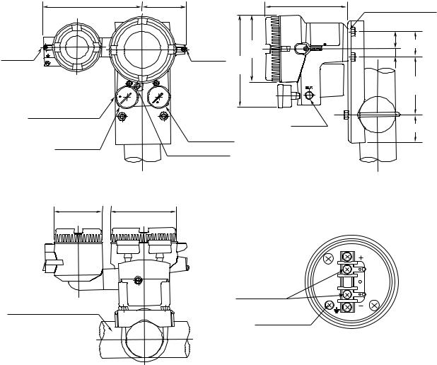
2.5 External Dimensions
165.5(6.52) |
74(2.91) |
137.5(5.41) |
Unit: mm |
|
Wall Mount Screw 2-M8 |
||||
|
|
|
||
|
Zero |
ø111 |
24(0.94) |
|
|
38(1.50) |
|||
Electrical |
Adjustment |
(4.37) |
14(0.55) |
|
Screw |
||||
153.5 |
|
|||
Connection |
|
|
||
|
(6.04) |
|
||
|
|
|
||
|
|
|
97 |
|
|
|
|
(3.82) |
|
Air Supply Connection |
|
|
|
|
|
|
Output |
47(1.85) |
|
|
|
Connection |
||
|
Output Gauge |
|
||
Supply Gauge |
A/M Transfer Switch |
|
|
|
|
|
|
||
|
(optional) |
|
|
|
ø81(3.19) ø111(4.37)
Terminal Configuration
Input Terminal
Nominal 50 mm (2-inch) Pipe
Ground Terminal
F0202.EPS
Figure 2.2 External Dimensions
2-3 |
IM 21B03D01-01E |

2. OVERVIEW
2.6 Part Names
Terminal box cover
Converter cover
Supply gauge
Zero adjustment
Output gauge
F0203.EPS
Figure 2.3 Part Names (1)
Span adjustment |
Case |
Zero adjustment |
||
|
|
|||
Electrical connection |
|
|
|
Amplifier |
Terminal board |
|
|
|
|
|
|
|
|
|
|
|
|
|
|
Ground terminal
F0204.EPS
Figure 2.4 Part Names (2)
2-4 |
IM 21B03D01-01E |
Loading...