


INSTRUCTION MANUAL
Model YF100
Vortex Flowmeter
(Integral Type, Remote Type)
Model YFA11
Vortex Flow Converter
(Remote Type)
(Style E)
IM 1F2B4-01-YIA
IM 1F2B4-01-YIA 1st Edition, March 1998 Printed in U.S.A.

TABLE OF CONTENTS
I. |
INTRODUCTION ....................................................................................................... |
1 |
||
|
1.1 |
General Overview ............................................................................................. |
1 |
|
|
1.2 |
Principle of Operation....................................................................................... |
1 |
|
|
|
1.2.1 |
Vortex shedding.................................................................................... |
1 |
|
|
1.2.2 |
K-factor ................................................................................................ |
2 |
|
|
1.2.3 |
Qmin .................................................................................................... |
3 |
|
|
1.2.4 |
Uniquely vortex .................................................................................... |
3 |
|
|
1.2.5 |
Vortex frequency .................................................................................. |
3 |
|
|
1.2.6 |
Available outputs .................................................................................. |
3 |
|
1.3 |
Standard Specifications ..................................................................................... |
4 |
|
|
1.4 |
Basic Sizing ...................................................................................................... |
7 |
|
|
|
1.4.1 |
Flowmeter sizing .................................................................................. |
7 |
|
1.5 |
Model and Suffix Codes ................................................................................... |
9 |
|
II. |
QUICK START ......................................................................................................... |
22 |
||
|
2.1 |
Parameter Setting in BRAIN Communications ................................................ |
22 |
|
|
2.2 |
YEWFLO Setup ............................................................................................. |
25 |
|
|
|
2.2.1 Liquid, gas or steam in mass flow units .............................................. |
26 |
|
|
|
2.2.2 Steam flow in energy units ................................................................. |
28 |
|
|
|
2.2.3 Gas volumetric referenced to standard conditions ............................... |
30 |
|
|
|
2.2.4 Liquid, gas, or steam in volumetric units at flowing conditions .......... |
32 |
|
|
2.3 |
Parameter Setting in HART Communications ................................................. |
34 |
|
|
|
2.3.1 |
Communication Specifications ........................................................... |
34 |
|
|
2.3.2 |
Hardware Recommendations .............................................................. |
35 |
III. |
INSTALLATION ....................................................................................................... |
36 |
||
|
3.1 |
Piping Requirements ....................................................................................... |
36 |
|
|
|
3.1.1 |
Pipe schedule ..................................................................................... |
37 |
|
|
3.1.2 Flow direction and orientation ............................................................ |
37 |
|
|
|
3.1.3 Pressure and temperature taps ............................................................ |
37 |
|
|
|
3.1.4 |
Flushing the pipe ................................................................................ |
38 |
|
|
3.1.5 |
Gaskets .............................................................................................. |
38 |
|
3.2 |
Installing the Vortex Meter .............................................................................. |
38 |
|
|
|
3.2.1 Installing the wafer style vortex meter ................................................ |
38 |
|
|
|
3.2.2 Installing the wafer style vortex meter horizontally ............................ |
39 |
|
|
|
3.2.3 Installing the wafer style vortex meter vertically ................................ |
39 |
|
|
|
3.2.4 Installing the flanged vortex meter ..................................................... |
40 |
|
|
|
3.2.5 Insulating vortex meters with integral converter ................................. |
40 |
|
|
|
3.2.6 |
Rotating the meter housing ................................................................. |
41 |
|
|
3.2.7 |
Remote converter terminal box rotation .............................................. |
41 |
|
|
3.2.8 |
Integral converter rotation .................................................................. |
41 |
|
|
3.2.9 |
Installing the remote converter ........................................................... |
42 |
|
3.3 |
Wiring |
........................................................................................................... |
43 |
|
|
3.3.1 Cables and wires (analog or pulse output wires only) ......................... |
43 |
|
|
|
3.3.2 Analog output, 2-wire type (4-20 mADC)........................................... |
43 |
|
|
|
3.3.3 |
Pulse output, 3-wire type .................................................................... |
44 |
|
|
3.3.4 |
Interconnection for remote converter .................................................. |
45 |
|
3.4 |
Cable |
........................................................................................................... |
46 |
|
|
3.4.1 Field terminating the signal cable (YF011-0*E).................................. |
46 |
|
|
3.5 |
Wiring Cautions .............................................................................................. |
49 |
|
|
|
3.5.1 |
Flameproof transmitter installation ..................................................... |
49 |
|
|
3.5.2 Cautions for insulation and dielectric strength testing ......................... |
49 |
|
|
|
3.5.3 Instruction document for FM explosionproof instruments ................... |
50 |
|
|
|
3.5.4 Wiring cautions for CSA intrinsic safety............................................. |
52 |
|
|
|
3.5.5 |
Wiring cautions for FM intrinsic safety .............................................. |
54 |
IM 1F2B4-01-YIA i

TABLE OF CONTENTS
IV. |
MAINTENANCE ...................................................................................................... |
58 |
||
|
4.1 |
How to |
........................................................................................................... |
58 |
|
|
4.1.1 |
Communicating with the YEWFLO remotely ..................................... |
59 |
|
|
4.1.2 |
Adjusting zero and span ..................................................................... |
60 |
|
|
4.1.3 |
Using self-diagnostics ........................................................................ |
61 |
|
|
4.1.4 |
Simulating an output/performing a loop check.................................... |
62 |
|
|
4.1.5 |
Changing the output mode to analog or pulse ..................................... |
63 |
|
|
4.1.6 |
Increasing gas and steam flow measurement accuracy by correcting |
|
|
|
|
for gas expansion ............................................................................... |
64 |
|
|
4.1.7 |
Activating Reynolds number correction.............................................. |
65 |
|
|
4.1.8 |
Activating mismatched pipe schedule (bore) correction ...................... |
66 |
|
|
4.1.9 |
Setting up and resetting the internal totalizer ...................................... |
67 |
|
|
4.1.10 |
Scaling the pulse output ..................................................................... |
68 |
|
|
4.1.11 |
Setting up user defined flow units ...................................................... |
69 |
|
|
4.1.12 |
Setting up the local LCD indicator display mode ................................ |
70 |
|
|
4.1.13 |
Setting the low cut flowrate ................................................................ |
71 |
|
|
4.1.14 |
Trimming the 4-20 mA analog output ................................................. |
72 |
|
|
4.1.15 |
Using the upload/download feature .................................................... |
74 |
|
4.2 |
Disassembly and Reassembly.......................................................................... |
75 |
|
|
|
4.2.1 |
Indicator/Totalizer removal ................................................................ |
75 |
|
|
4.2.2 |
Amplifier replacement ........................................................................ |
75 |
|
4.3 |
Vortex Shedder Assembly Removal ................................................................ |
76 |
|
|
|
4.3.1 |
Removal of shedder from remote converter type................................. |
76 |
|
|
4.3.2 |
Removal of the shedder from integral type ......................................... |
77 |
|
4.4 |
Reassembly Cautions ...................................................................................... |
78 |
|
|
|
4.4.1 |
YEWFLO shedder bolt torque procedures .......................................... |
78 |
|
4.5 |
YEWFLO Style "E" Amplifier Calibration Procedure ..................................... |
81 |
|
|
|
4.5.1 |
General amplifier checkout ................................................................ |
82 |
|
|
4.5.2 |
Analog output test .............................................................................. |
82 |
|
|
4.5.3 |
Pulse output test ................................................................................. |
83 |
V. |
PARAMETER SETTING/CONFIGURATION ....................................................... |
84 |
||
|
5.1 |
Notes on the TBL optional digital display ....................................................... |
84 |
|
|
|
5.1.1 Display contents in display section ..................................................... |
85 |
|
VI. |
TROUBLESHOOTING ............................................................................................ |
88 |
||
|
6.1 |
Error Code Listing .......................................................................................... |
88 |
|
|
6.2 |
Operating Procedures ...................................................................................... |
89 |
|
|
6.3 |
Flow Computation .......................................................................................... |
92 |
|
|
|
6.3.1 |
Variable definitions ............................................................................ |
92 |
|
|
6.3.2 |
Flow conversion factor ....................................................................... |
93 |
|
6.4 |
Signal Conditioning ........................................................................................ |
94 |
|
|
|
6.4.1 YEWFLO Style "E" signal adjustment procedure ............................... |
94 |
|
|
|
6.4.2 |
Problem solving ................................................................................. |
94 |
|
|
6.4.3 |
Piping checkout procedure ................................................................. |
94 |
|
|
6.4.4 |
Noise balance adjustment ................................................................... |
95 |
|
|
6.4.5 |
Noise judge ........................................................................................ |
96 |
|
|
6.4.6 |
TLA adjustment ................................................................................. |
96 |
|
|
6.4.7 |
Low-cut flowrate adjustment .............................................................. |
97 |
|
|
6.4.8 |
High-frequency filter adjustment ........................................................ |
97 |
|
6.5 |
Flowcharts ...................................................................................................... |
98 |
|
|
|
6.5.1 No flowmeter output under flowing conditions ................................... |
98 |
|
|
|
6.5.2 |
Flowmeter output with no flow......................................................... |
100 |
|
|
6.5.3 |
Large flowmeter errors ..................................................................... |
101 |
|
|
6.5.4 Output is unstable when flowrate is low ........................................... |
102 |
|
IM 1F2B4-01-YIA ii

|
TABLE OF CONTENTS |
|
VII. GLOSSARY |
......................................................................................................... |
103 |
APPENDIXES: |
|
|
Appendix A: |
Parameter Details ............................................................................. |
107 |
Appendix B: |
HART Parameter Details ................................................................... |
115 |
Appendix C: |
Customer Maintenance Parts List |
|
Appendix D: |
Dimensional Diagrams |
|
INDEX |
|
|
IM 1F2B4-01-YIA iii

INTRODUCTION
I.INTRODUCTION
1.1GENERAL OVERVIEW
This manual provides installation, parameter setting, calibration, maintenance and troubleshooting instructions for the YEWFLO Vortex flowmeter. Also included are standard specifications, model code definitions, dimensional drawings and a parts lists.
All YEWFLO’s are shipped pre-configured for your application. Therefore, if you included correct process conditions with your order, no electronic setup or parameter setting is required. For piping and wiring connections, refer to the Installation section.
If your process conditions have changed since your order was placed, please refer to the ‘QUICK START’ section which is designed to simplify configuration of the YEWFLO software parameters. Please refer to the index for immediate access to a specific procedure or the glossary located at the end of this manual for further information on a specific term.
If you have any questions concerning the YEWFLO you received, please contact your local Yokogawa Industrial Automation Representative or our headquarters office in Newnan, GA at 770-254-0400.
If you have technical questions regarding the installation, operation, setup or application of a YEWFLO, please contact our Technical Assistance Center (TAC) at 800-524-SERV.
Yokogawa has manufactured this instrument according to rigorous ISO 9000 quality standards. To ensure quality performance we recommend referencing our YEWFLO sizing program to determine the level at which your application should be run as well as a straight meter run of 20 diameters upstream and 5 diameters downstream. In addition to these suggestions, please follow the instructions in this manual carefully.
We are not responsible for any instrument’s performance, if that instrument has not been properly applied or installed in accordance with this manual, nor can we be responsible for the performance of any instrument which has been modified or repaired by an unauthorized service center.
Note: Existing YEWFLO Style C vortex flowmeters may be upgraded to provide the features and benefits of the New microprocessor-based Style "E" YEWFLO.
1.2PRINCIPLE OF OPERATION
1.2.1 Vortex shedding
How many of you have seen a flag flapping in the breeze on a windy day? Everybody has. How many of you have noticed that the flag flaps faster as the wind blows faster? Few haven’t. When you see a flag flapping in the breeze, you are witnessing the same phenomenon that makes a vortex flowmeter work. The flapping frequency is proportional to the velocity of the wind, and it’s linear! The flapping is caused by a vortex alternately being created on either side of the flag, and moving downstream with the wind. The vortex is a swirl of low pressure, like a tornado, that pulls the flag in the direction of the vortex. The passing of alternating vortices down the length of the flag causes it to flap. The faster the wind blows, the faster these vortices are created, and the faster the flag flaps. Frequency is proportional to velocity .
IM 1F2B4-01-YIA
Page 1
INTRODUCTION
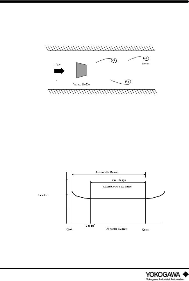
The flapping flag is a familiar example of vortex shedding that everyone should be comfortable with. Here’s how it’s used in a vortex flowmeter. A non-streamlined part (bluff body) is inserted in the flow stream, this obstruction in the pipe causes vortices to be alternately created (shed). We call this part the ‘shedder bar’. The shedder bar in a YEWFLO performs two functions, it creates the vortices, and with the addition of our piezoelectric crystals senses them too. The crystals generate an alternating voltage waveform whose frequency is proportional to fluid velocity. The rest of the magic is taken care of in the electronics.
Figure 1.2.1: Karman Vortices
1.2.2K-factor
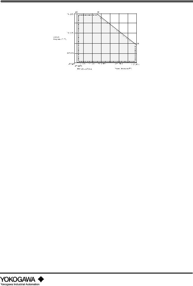
The most important fact about vortex shedding is that once the physical geometry, (pipe I.D., shedder bar width, etc.), are fixed, the frequency vs. flowrate (K-factor (pulse/gallon)) is unaffected by changes in viscosity, density or pressure over the operating range of the specific application. To determine the operating range use the YEWFLO Sizing program. On the other hand, an orifice plate is directly affected by changes in any of these parameters. There is a very small temperature effect due to expansion or contraction of the shedder bar width, which is easily compensated. Therefore, the K- factor created in our flow stand (all YEWFLOs are wet flow calibrated) on water, is accurate for gas too! Not so with an orifice plate. The benefit here is simplified calculations, and fewer things that can effect accuracy .
Figure 1.2.2: Relationship between K-factor and Reynolds Numbers
IM 1F2B4-01-YIA
Page 2

INTRODUCTION
1.2.3Qmin
Those of you who haven’t used many vortex flowmeters may be wondering, ‘Why do we need to know viscosity, density, pressure and temperature?’. While the K-factor is unaffected by changes in viscosity, density and pressure, the velocity at which vortices begin to be created and become stable enough to measure accurately will vary. We refer to this velocity as Qmin, stated in desired flow units GPM, SCFH, etc. Here’s an example to help you understand. Let’s go back to the flag example. We’ve all seen the flag flapping in the breeze; however, on some days we can feel the breeze blowing, but the flag isn’t flapping. Why not? For the flag to flap, there must be enough breeze blowing, or energy, to lift the flag and create fully developed vortices. This is the same thing that happens in the vortex flowmeter.
The higher the fluid viscosity, the higher the velocity (more energy) required to start vortex shedding. On the other hand, the higher the density, the lower the velocity needed to start vortex shedding. In gases, viscosity and density can vary with pressure and temperature. Sounds complicated, but compared to an orifice plate it’s quite simple. By using the YEWFLO sizing program, vortex meter selection is simple. Simply enter the process conditions, the program will prompt you for them, and presto, a performance table for all meter sizes is generated. This performance table will help you select the best YEWFLO for the application.
1.2.4Uniquely vortex
Vortex shedding flowmeters measure flow digitally. This means, amplitude of the vortex signal is unimportant. As long as the flow is above the Qmin threshold, only the presence or absence of a vortex is important. Just like digital electronics, as long as the voltage is above or below a threshold value, it is either on or off. Digital flow measurement means no zero drift or span shift . Orifice plate flowmeters, for example, cannot make this claim, even if they are using microprocessor-based digital D/P transmitters, they still measure the small amplitude of deflection caused by differential pressure, and changes in temperature or pressure can shift zero and span.
1.2.5Vortex frequency
The YEWFLO uses piezoelectric crystals embedded in the shedder bar . Note that they are 1) hermetically sealed , and 2) surrounded by a heavy wall thickness , to protect them from the environment and the process. The positioning of the crystals is important. Although one crystal primarily measures flow frequency, it unfortunately picks up some pipe vibration noise. The other crystal is positioned such that it picks up primarily the pipe vibration noise. By electronically subtracting these two signals, we are able to obtain a high signal to noise ratio for the flow signal . The new Style "E" body design also improves the signal to noise ratio, by stiffening the shedder bar mounting in the measurement plane, further isolating it from pipe vibration.
1.2.6Available outputs
After processing the digital vortex frequency as described above, what outputs can you get? You can select either 4-20 mA output or voltage pulse, digital output. Output is selected by setting jumpers on the amplifier board, and the setting the software for pulse or analog output. Analog output is twowire, and pulse output is a three-wire connection (for details see the wiring section). The pulse output can be scaled over a range of 0-6000 Hz, down or up to maximize pulse resolution. Scaling up the frequency output can be done to improve resolution. The pulse output is also capable of driving many electromechanical totalizers directly without additional power.
IM 1F2B4-01-YIA
Page 3

INTRODUCTION
1.3STANDARD SPECIFICATIONS
NOTE: For special applications, please contact your local Yokogawa Industrial Automation representative to discuss possible enhancements to these standard specifications.
Fluids to be measured: Liquid, gas or steam
Performance specifications:
Repeatability: 0.2% of reading
Accuracy and velocity range :
Fluid |
Accuracy: Pulse Output |
Accuracy: Analog Output |
Velocity |
Liquid |
±0.8% of reading |
±0.8% of reading plus |
up to 32 ft/sec |
|
|
±0.1% of full scale |
|
Gas or |
±0.8% of reading |
±0.8% of reading plus |
up to 115 ft/sec |
Steam |
|
±0.1% of full scale |
|
|
±1.5% of reading |
±1.5% of reading plus |
from 115 ft/sec |
|
|
±0.1% of full scale |
to 262 ft/sec |
Note: Gas accuracy can be improved to 0.8% over the full range by built-in software compensation. (See how to section 4.10.)
Output signal:
Analog: 4 to 20 mADC
Pulse: Low level 0 to 2 V
High level Vs - 2V ( Vs = input supply voltage)
Pulse width 50% duty cycle
Ambient temperature limits: |
|
|
|
-40º to 175ºF |
(-40º to 80ºC): |
standard unit w/o agency approval ratings |
|
-20º to 175ºF |
(-30º to 80ºC): |
with optional digital indicator |
|
-40º to 140ºF |
(-40º to 60ºC): |
with FM explosion-proof rating |
|
-40º to 120ºF |
(-40º to 50ºC): |
with CSA intrinsically safe rating for integral converter |
|
-40º to 175ºF |
(-40º to 80ºC): |
with CSA intrinsically safe rating for remote converter |
|
Process temperature limits: |
|
|
|
Standard remote converter: |
-40º to 575ºF |
(-40º to 300ºC) |
|
HPT remote converter: |
-40º to 755ºF |
(-40º to 402ºC) |
|
Cryogenic remote converter: |
-320º to 300ºF (-200º to 150ºC) |
||
Integral converter: |
See Figure 1.3.1 |
||
Storage temperature limits: |
|
|
|
Integral or remote standard unit: |
-40º to 176ºF (-40º to 80ºC) |
||
With integral indicator or totalizer: |
-22º to 80ºF |
(-30º to 140ºC) |
|
IM 1F2B4-01-YIA
Page 4
INTRODUCTION
Figure 1.3.1: Operating temperature range for integral type converter
Power supply and load resistance: |
|
|
Analog output: |
|
17 to 42 VDC (see Figure 1.3.2) |
Pulse output: |
|
14 to 30 VDC |
Maximum output wire resistance: |
50 ohms |
|
Maximum line capacitance: |
0.22 microfarad |
|
Ambient humidity limits: |
|
|
5 to 100% relative humidity |
|
|
Process pressure limits: |
|
|
-14.7 psi (full vacuum) to flange rating |
|
|
Materials of construction: |
|
|
Process wetted parts: |
|
|
Body: |
CF8M (ANSI 316 stainless steel) or Hastelloy C (equivalent of |
|
|
ASTM494, CW12MW) |
|
Shedder bar: |
Duplex stainless steel (CD4MCU equivalent to ANSI 329 stainless |
|
|
steel) or Hastelloy C (equivalent of ASTM494, CW12MW) |
|
Non-wetted parts: |
|
|
Amplifier housing: |
Aluminum alloy casting |
|
Paint: |
Case - Polyurethane resin baked coating, frosty white |
|
|
Cover - Polyurethane resin baked coating, deep, sea moss green |
|
IM 1F2B4-01-YIA
Page 5
INTRODUCTION
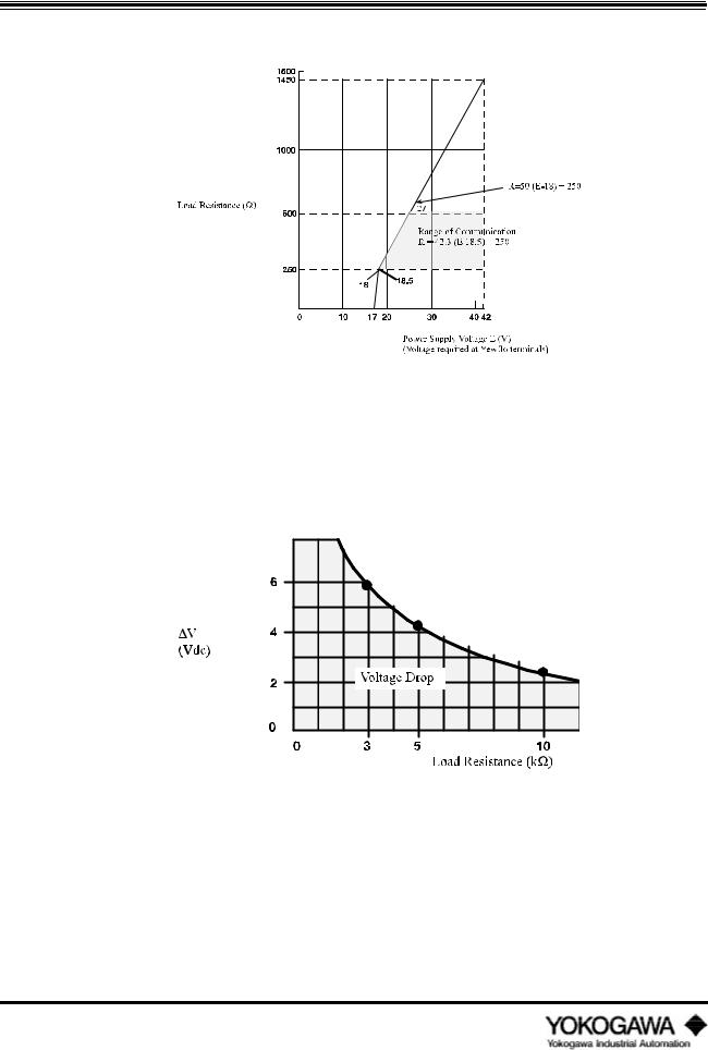
Analog Output :
Figure 1.3.2: Relationship between power supply voltage and load resistance for analog output version
Pulse Output: Pulse output voltage = Vs-2v- v
where v = due to external load resistance Vs = Power Supply Voltage
2v = 2 volts
Figure 1.3.3: Load resistance vs. pulse output voltage drop
IM 1F2B4-01-YIA
Page 6
INTRODUCTION
1.4BASIC SIZING
1.4.1Flowmeter sizing
Notes: 1) This table assumes standard conditions of 59ºF (15ºC).
2)Maximum flowrates are based on 32 ft/sec.
3)These figures are approximations. Refer to the Yewflo sizing program for the exact minimum and maximum for your application.
4)The values shown in parenthesis is the minimum linear flowrate.
5)Proper pipe bracing may be required to obtain minimum flowrate.
LIQUID
Nominal |
Size |
|
Minimum and Maximum |
|
|
mm |
inch |
Measurable Flow Rates in U.S. gpm1 |
|||
15 |
½ |
1.3 |
-4.2 |
and |
27 |
25 |
1 |
2 |
-7.3 |
and |
82 |
40 |
1½ |
5.9 |
-11.3 |
and |
196 |
50 |
2 |
9.8 |
-14.5 |
and |
324 |
80 |
3 |
20 |
|
and |
628 |
100 |
4 |
33 |
|
and |
1100 |
150 |
6 |
79 |
|
and |
2400 |
200 |
8 |
150 |
|
and |
4290 |
250 |
10 |
265 |
|
and |
6460 |
300 |
12 |
300 |
|
and |
9260 |
Table 1.4.1: Water -Flowmeter Range
GAS
Nominal Size |
Flow Rate |
|
Minimum |
Linear and |
Maximum |
Measurable |
Air Flow Rates in SCFH |
|
|
(inches) |
Limits |
|
(Standard |
conditions |
are 59ºF |
and 14.7 psia) |
at process line pressure |
|
|
|
|
0 psig |
50 psig |
100 psig |
150 psig |
200 psig |
300 psig |
400 psig |
500 psig |
½ |
min |
172 |
361 |
500 |
719 |
939 |
1379 |
1822 |
2266 |
|
max |
1700 |
7492 |
13302 |
19128 |
24967 |
36692 |
48454 |
60266 |
|
|||||||||
|
|||||||||
|
|
|
|
|
|
|
|
|
|
1 |
min |
400 |
839 |
1118 |
1486 |
1940 |
2851 |
3765 |
4683 |
|
max |
5267 |
23215 |
41217 |
59268 |
77362 |
113692 |
150137 |
186737 |
|
|||||||||
|
|||||||||
|
|
|
|
|
|
|
|
|
|
1½ |
min |
792 |
1919 |
3037 |
4061 |
5026 |
6838 |
8970 |
11157 |
|
max |
1267 |
55397 |
98355 |
141428 |
184604 |
271296 |
358263 |
445599 |
|
|||||||||
|
|||||||||
|
|
|
|
|
|
|
|
|
|
2 |
min |
1313 |
2756 |
4080 |
5867 |
7658 |
11254 |
14862 |
18485 |
|
max |
20821 |
91779 |
162951 |
234313 |
305846 |
449474 |
593557 |
738253 |
|
|||||||||
|
|||||||||
|
|
|
|
|
|
|
|
|
|
3 |
min |
2534 |
5321 |
7877 |
11326 |
14784 |
21726 |
28691 |
35685 |
|
max |
40196 |
177182 |
314580 |
452347 |
590443 |
867720 |
1145876 |
1425214 |
|
|||||||||
|
|||||||||
|
|
|
|
|
|
|
|
|
|
4 |
min |
4423 |
10710 |
16953 |
22670 |
28055 |
38174 |
50076 |
62283 |
|
max |
70157 |
309249 |
549061 |
789516 |
1030544 |
1514497 |
1999984 |
2487535 |
|
|||||||||
|
|||||||||
|
|
|
|
|
|
|
|
|
|
6 |
min |
9685 |
29678 |
46977 |
64927 |
84749 |
124548 |
164473 |
204567 |
|
max |
153618 |
677145 |
1202247 |
1728757 |
2256524 |
3316208 |
4379250 |
5446812 |
|
|||||||||
|
|||||||||
|
|
|
|
|
|
|
|
|
|
8 |
min |
20851 |
68121 |
107827 |
144185 |
178437 |
242799 |
303286 |
265774 |
|
max |
274675 |
1010761 |
2149664 |
3091086 |
4034753 |
5929510 |
7830269 |
9739113 |
|
|||||||||
|
|||||||||
|
|
|
|
|
|
|
|
|
|
10 |
min |
37370 |
122437 |
193804 |
259153 |
320716 |
436397 |
545115 |
649056 |
|
max |
424752 |
1872295 |
3324193 |
4779987 |
6239253 |
9169263 |
12108556 |
15060351 |
|
|||||||||
|
|||||||||
|
|
|
|
|
|
|
|
|
|
12 |
min |
53518 |
175343 |
277549 |
371134 |
459300 |
624968 |
780663 |
929518 |
|
max |
608291 |
2681328 |
4760604 |
6845457 |
8935284 |
13131375 |
17340759 |
21568047 |
|
|
|
|
|
|
|
|
|
|
Table 1.4.2: Air-Flowmeter Range
Notes: 1) Maximum flowrates are based on 262 ft/sec.
2)These figures are approximations. Refer to the sizing program for the exact minimum and maximum flowrates for your application.
IM 1F2B4-01-YIA
Page 7

INTRODUCTION
STEAM
Nominal Size |
Flow Rate |
|
|
Minimum |
Linear and Maximum |
Measurable |
Saturated |
Steam Flow Rates in lb/hr |
|
|
|||
(inches) |
Limits |
|
|
|
|
|
at |
process line |
pressure |
|
|
|
|
|
|
15 psig |
25 psig |
50 psig |
75 psig |
100 psig |
|
125 psig |
150 psig |
175 psig |
200 psig |
250 psig |
300 psig |
½ |
min |
12.8 |
14.6 |
18.4 |
21.5 |
24.1 |
|
26.5 |
28.7 |
30.7 |
32.6 |
36.6 |
43.4 |
|
max |
122 |
161 |
254 |
346 |
437 |
|
527 |
616 |
705 |
765 |
973 |
1154 |
|
|
||||||||||||
1 |
min |
29.7 |
34 |
42.8 |
49.9 |
56.1 |
|
61.6 |
66.6 |
71.3 |
75.7 |
83.7 |
91.2 |
|
max |
379 |
498 |
788 |
1071 |
1353 |
|
1632 |
1910 |
2185 |
2464 |
3014 |
357 |
|
|
||||||||||||
1½ |
min |
58.7 |
67.3 |
84.6 |
98.6 |
118 |
|
137 |
156 |
173 |
191 |
224 |
257 |
|
max |
905 |
1188 |
1879 |
2554 |
3228 |
|
3894 |
4557 |
5215 |
5879 |
7192 |
8530 |
|
|
||||||||||||
2 |
min |
97.5 |
111 |
140 |
164 |
184 |
|
202 |
219 |
234 |
248 |
298 |
354 |
|
max |
1500 |
1969 |
3113 |
4232 |
5349 |
|
6452 |
7550 |
8639 |
9740 |
11916 |
14133 |
|
|
||||||||||||
3 |
min |
188 |
216 |
271 |
316 |
355 |
|
390 |
422 |
452 |
480 |
576 |
683 |
|
max |
2895 |
3800 |
6010 |
8170 |
10326 |
|
12455 |
14576 |
16678 |
18804 |
23004 |
27283 |
|
|
||||||||||||
4 |
min |
328 |
376 |
472 |
551 |
659 |
|
766 |
869 |
967 |
1065 |
1251 |
1434 |
|
max |
5054 |
6633 |
10490 |
14260 |
18023 |
|
21739 |
25440 |
29109 |
32820 |
40150 |
47620 |
|
|
||||||||||||
6 |
min |
719 |
824 |
1184 |
1515 |
1827 |
|
2122 |
2407 |
2681 |
2951 |
3467 |
3974 |
|
max |
11065 |
14523 |
22969 |
31224 |
39463 |
|
47600 |
55705 |
63739 |
71864 |
87914 |
104270 |
|
|
||||||||||||
8 |
min |
1549 |
1885 |
2720 |
3477 |
4193 |
|
4872 |
5525 |
6153 |
6773 |
7958 |
9122 |
|
max |
19785 |
25968 |
41070 |
55830 |
70561 |
|
85111 |
99603 |
113968 |
128496 |
157194 |
186439 |
|
|
||||||||||||
10 |
min |
2725 |
3387 |
4888 |
6249 |
7536 |
|
8756 |
9930 |
11060 |
12174 |
14304 |
16396 |
|
max |
30596 |
40157 |
63509 |
86334 |
109114 |
|
131614 |
154024 |
176238 |
198703 |
243081 |
288305 |
|
|
||||||||||||
12 |
min |
3903 |
4851 |
7000 |
8949 |
10793 |
|
12539 |
14220 |
15839 |
17434 |
20485 |
23481 |
|
max |
43816 |
57590 |
90952 |
123640 |
156263 |
|
188485 |
220578 |
252392 |
284564 |
348119 |
412883 |
|
|
|
|
|
|
|
|
|
|
|
|
|
|
Table 1.4.3: Steam - Flowmeter Range
Notes: 1) Maximum flowrates are based on 262 ft/sec.
2)These figures are approximations. Refer to the sizing program for the exact minimum and maximum flowrates for your applications.
Nominal Size |
Internal Diameter |
Cross Sectional |
Nominal Pulse Rate |
Nominal |
K-factor |
(inches) |
(inches) |
Area (ft2) |
(Hz/ft/s) |
Pulse/US gal |
Pulse/ft3 |
½ |
0.57 |
0.0018 |
19.1 |
1423 |
10645 |
1 |
1.01 |
0.0056 |
10.8 |
259 |
1940 |
1½ |
1.56 |
0.133 |
7.05 |
70.8 |
530 |
2 |
2.01 |
0.022 |
5.59 |
33.9 |
253 |
3 |
2.8 |
0.043 |
4.02 |
12.6 |
94.3 |
4 |
3.69 |
0.074 |
3 |
5.39 |
40.3 |
6 |
5.46 |
0.163 |
2.03 |
1.67 |
12.5 |
8 |
7.31 |
0.291 |
1.52 |
0.7 |
5.24 |
10 |
9.09 |
0.45 |
1.23 |
0.366 |
2.74 |
12 |
10.9 |
0.645 |
1.03 |
0.213 |
1.59 |
Table 1.4.4: Nominal K-factor and general flowmeter information
IM 1F2B4-01-YIA
Page 8

YEWFLO |
*E |
STAINLESS |
|
|
|||
*E VORTEX FLOWMETERS |
WAFER |
||
|
|||
|
|
|
|
|
|
|
|
|
|
|
MODEL |
|
|
YEWFLO |
*E - STAINLESS |
|
WAFER |
|
|
||
CODE |
|
|
|
|
|
|
|
|
|
|
YF101 |
0.5" I.D. Stainless Steel Wafer |
|
|
|
|
|
|
|||
YF102 |
1.0" I.D. Stainless Steel Wafer |
|
|
|
|
|
|
|||
YF104 |
1.5" I.D. Stainless Steel Wafer |
|
|
|
|
|
|
|||
YF105 |
2.0" I.D. Stainless Steel Wafer |
|
|
|
|
|
|
|||
YF108 |
3.0" I.D. Stainless Steel Wafer |
|
|
|
|
|
|
|||
YF110 |
4.0" I.D. Stainless Steel Wafer |
|
|
|
|
|
|
|||
|
|
|
|
|
CERTIFICATION |
|
|
|
|
|
|
-AAU |
Integral, 4-20 mA or pulse |
|
|
|
|
|
|
||
|
-AAD |
Integral, 4-20 mA for intrinsic safety |
|
|
|
|
|
|||
|
-AAR |
Integral, pulse output for intrinsic safety |
||||||||
|
-NNN |
Remote converter |
|
|
|
|
|
|
||
|
|
PROCESS |
CONNECTIONS |
(wafer |
style for mounting between) |
|||||
|
|
B1 |
ANSI 150 lb Wafer Flanges |
|
|
|
|
|
||
|
|
B2 |
ANSI 300 lb Wafer Flanges |
|
|
|
|
|
||
|
|
B3 |
ANSI 600 lb Wafer Flanges |
|
|
|
|
|
||
|
|
|
|
|
|
MATERIALS |
|
|
|
|
|
|
|
A-S3S3*E |
Stainless Steel shedder bar & body |
||||||
|
|
|
|
|
|
CERTIFICATION |
|
|
||
|
|
|
|
/FM F |
FM explosionproof housing w/FM stamp |
|||||
|
|
|
|
/FM S |
FM intrinsic safety w/FM stamp |
|||||
|
|
|
|
/CSF |
CSA explosionproof housing w/CSA stamp |
|||||
|
|
|
|
/CSS |
CSA intrinsic safety w/CSA stamp |
|||||
|
|
|
|
|
|
|
OPTIONS |
|
|
|
|
|
|
|
|
/HART |
HART communications |
||||
|
|
|
|
|
/HPT |
High temperature |
||||
|
|
|
|
|
/TBL |
Local interface |
||||
|
|
|
|
|
/EPF |
Epoxy-coated electronics housing |
||||
|
|
|
|
|
/OSW |
Oxygen cleaning |
||||
|
|
|
|
|
/BLT |
304 SS nuts and bolts |
||||
|
|
|
|
|
/SCT |
Stainless Steel tags wired into place |
||||
|
|
|
|
|
|
|
|
|
|
|
IM 1F2B4-01-YIA
Page 9

STAINLESS |
*E |
YEWFLO |
FLANGED 150# |
*E VORTEX FLOWMETERS |
|
|
||
|
|
|
|
|
|
|
|
|
MODEL |
|
YEWFLO *E - |
STAINLESS |
150# |
FLANGE |
|
||||
CODE |
|
|
|
|
|
|
|
|
|
|
|
|
|
|
|
|
|
||||
YF101 |
0.5" I.D. Stainless Steel 150 lb RF flange |
|
|
|
|
|
||||
YF102 |
1.0" I.D. Stainless Steel 150 lb RF flange |
|
|
|
|
|
||||
YF104 |
1.5" I.D. Stainless Steel 150 lb RF flange |
|
|
|
|
|
||||
YF105 |
2.0" I.D. Stainless Steel 150 lb RF flange |
|
|
|
|
|
||||
YF108 |
3.0" I.D. Stainless Steel 150 lb RF flange |
|
|
|
|
|
||||
YF110 |
4.0" I.D. Stainless Steel 150 lb RF flange |
|
|
|
|
|
||||
YF115 |
6.0" I.D. Stainless Steel 150 lb RF flange |
|
|
|
|
|
||||
YF120 |
8.0" I.D. Stainless Steel 150 lb RF flange |
|
|
|
|
|
||||
YF125 |
10.0" I.D. Stainless Steel 150 lb RF flange |
|
|
|
|
|
||||
YF130 |
12.0" I.D. Stainless Steel 150 lb RF flange |
|
|
|
|
|
||||
|
|
|
|
|
|
|
|
|
||
|
|
|
|
|
CONFIGURATION |
|
|
|
|
|
|
-AAU |
Integral, 4-20 mA or pulse |
|
|
|
|
|
|
||
|
-AAD |
Integral, 4-20 mA for intrinsic safety |
||||||||
|
-AAR |
Integral, pulse output for intrinsic safety |
||||||||
|
-NNN |
Remote converter |
|
|
|
|
|
|
||
|
|
|
|
|
|
|
|
|
|
|
|
|
|
|
PROCESS |
CONNECTIONS |
|
|
|
||
|
|
A1 |
ANSI 150 lb RF flanges |
|
|
|
|
|
||
|
|
|
|
|
|
|
|
|
|
|
|
|
|
|
|
|
MATERIALS |
|
|
|
|
|
|
|
A-S3S3*E |
Stainless Steel shedder bar & body |
||||||
|
|
|
|
|
|
|
|
|
|
|
|
|
|
|
|
|
CERTIFICATION |
|
|
||
|
|
|
|
/FM F |
FM explosionproof housing w/FM stamp |
|||||
|
|
|
|
/FM S |
FM intrinsic safety w/FM stamp |
|||||
|
|
|
|
/CSF |
CSA explosionproof housing w/CSA stamp |
|||||
|
|
|
|
/CSS |
CSA intrinsic safety w/CSA stamp |
|||||
|
|
|
|
|
|
|
|
|
|
|
|
|
|
|
|
|
|
OPTIONS |
|
|
|
|
|
|
|
|
/HART |
HART communications |
||||
|
|
|
|
|
/HPT |
High temperature |
||||
|
|
|
|
|
/TBL |
Local interface |
||||
|
|
|
|
|
/EPF |
Epoxy-coated electronics housing |
||||
|
|
|
|
|
/OSW |
Oxygen cleaning |
||||
|
|
|
|
|
/SCT |
Stainless Steel tags wired into place |
||||
|
|
|
|
|
|
|
|
|
|
|
IM 1F2B4-01-YIA
Page 10

YEWFLO |
*E |
STAINLESS |
|
|
|||
*E VORTEX FLOWMETERS |
FLANGED 300# |
||
|
|||
|
|
|
|
|
|
|
|
|
|
|
MODEL |
|
YEWFLO *E - |
STAINLESS |
300# |
FLANGE |
|
||||
CODE |
|
|
|
|
|
|
|
|
|
|
|
|
|
|
|
|
|
||||
YF101 |
0.5" I.D. Stainless Steel 300 lb RF flange |
|
|
|
|
|
||||
YF102 |
1.0" I.D. Stainless Steel 300 lb RF flange |
|
|
|
|
|
||||
YF104 |
1.5" I.D. Stainless Steel 300 lb RF flange |
|
|
|
|
|
||||
YF105 |
2.0" I.D. Stainless Steel 300 lb RF flange |
|
|
|
|
|
||||
YF108 |
3.0" I.D. Stainless Steel 300 lb RF flange |
|
|
|
|
|
||||
YF110 |
4.0" I.D. Stainless Steel 300 lb RF flange |
|
|
|
|
|
||||
YF115 |
6.0" I.D. Stainless Steel 300 lb RF flange |
|
|
|
|
|
||||
YF120 |
8.0" I.D. Stainless Steel 300 lb RF flange |
|
|
|
|
|
||||
YF125 |
10.0" I.D. Stainless Steel 300 lb RF flange |
|
|
|
|
|
||||
YF130 |
12.0" I.D. Stainless Steel 300 lb RF flange |
|
|
|
|
|
||||
|
|
|
|
|
|
|
|
|
||
|
|
|
|
|
CONFIGURATION |
|
|
|
|
|
|
-AAU |
Integral, 4-20 mA or pulse |
|
|
|
|
|
|
||
|
-AAD |
Integral, 4-20 mA for intrinsic safety |
||||||||
|
-AAR |
Integral, pulse output for intrinsic safety |
||||||||
|
-NNN |
Remote converter |
|
|
|
|
|
|
||
|
|
|
|
|
|
|
|
|
|
|
|
|
|
|
PROCESS |
CONNECTIONS |
|
|
|
||
|
|
A2 |
ANSI 300 lb RF flanges |
|
|
|
|
|
||
|
|
|
|
|
|
|
|
|
|
|
|
|
|
|
|
|
MATERIALS |
|
|
|
|
|
|
|
A-S3S3*E |
Stainless Steel shedder bar & body |
||||||
|
|
|
|
|
|
|
|
|
|
|
|
|
|
|
|
|
CERTIFICATION |
|
|
||
|
|
|
|
/FM F |
FM explosionproof housing w/FM stamp |
|||||
|
|
|
|
/FM S |
FM intrinsic safety w/FM stamp |
|||||
|
|
|
|
/CSF |
CSA explosionproof housing w/CSA stamp |
|||||
|
|
|
|
/CSS |
CSA intrinsic safety w/CSA stamp |
|||||
|
|
|
|
|
|
|
|
|
|
|
|
|
|
|
|
|
|
OPTIONS |
|
|
|
|
|
|
|
|
/HART |
HART communications |
||||
|
|
|
|
|
/HPT |
High temperature |
||||
|
|
|
|
|
/TBL |
Local interface |
||||
|
|
|
|
|
/EPF |
Epoxy-coated electronics housing |
||||
|
|
|
|
|
/OSW |
Oxygen cleaning |
||||
|
|
|
|
|
/SCT |
Stainless Steel tags wired into place |
||||
|
|
|
|
|
|
|
|
|
|
|
IM 1F2B4-01-YIA
Page 11

STAINLESS |
*E |
YEWFLO |
|
||
FLANGED 600# |
*E VORTEX FLOWMETERS |
|
|
|
|
|
|
|
|
|
|
MODEL |
|
YEWFLO *E - |
STAINLESS |
600# |
FLANGE |
|
||||
CODE |
|
|
|
|
|
|
|
|
|
|
YF101 |
0.5" I.D. Stainless Steel 600 lb RF flange |
|
|
|
|
|
||||
YF102 |
1.0" I.D. Stainless Steel 600 lb RF flange |
|
|
|
|
|
||||
YF104 |
1.5" I.D. Stainless Steel 600 lb RF flange |
|
|
|
|
|
||||
YF105 |
2.0" I.D. Stainless Steel 600 lb RF flange |
|
|
|
|
|
||||
YF108 |
3.0" I.D. Stainless Steel 600 lb RF flange |
|
|
|
|
|
||||
YF110 |
4.0" I.D. Stainless Steel 600 lb RF flange |
|
|
|
|
|
||||
YF115 |
6.0" I.D. Stainless Steel 600 lb RF flange |
|
|
|
|
|
||||
YF120 |
8.0" I.D. Stainless Steel 600 lb RF flange |
|
|
|
|
|
||||
|
|
|
|
|
|
|
|
|
||
|
|
|
|
|
CONFIGURATION |
|
|
|
|
|
|
-AAU |
Integral, 4-20 mA or pulse |
|
|
|
|
|
|
||
|
-AAD |
Integral, 4-20 mA for intrinsic safety |
||||||||
|
-AAR |
Integral, pulse output for intrinsic safety |
||||||||
|
-NNN |
Remote converter |
|
|
|
|
|
|
||
|
|
|
|
|
|
|
|
|
|
|
|
|
|
|
PROCESS |
CONNECTIONS |
|
|
|
||
|
|
A3 |
ANSI 600 lb RF flanges |
|
|
|
|
|
||
|
|
|
|
|
|
|
|
|
|
|
|
|
|
|
|
|
MATERIALS |
|
|
|
|
|
|
|
A-S3S3*E |
Stainless Steel shedder bar & body |
||||||
|
|
|
|
|
|
|
|
|
|
|
|
|
|
|
|
|
CERTIFICATION |
|
|
||
|
|
|
|
/FM F |
FM explosionproof housing w/FM stamp |
|||||
|
|
|
|
/FM S |
FM intrinsic safety w/FM stamp |
|||||
|
|
|
|
/CSF |
CSA explosionproof housing w/CSA stamp |
|||||
|
|
|
|
/CSS |
CSA intrinsic safety w/CSA stamp |
|||||
|
|
|
|
|
|
|
|
|
|
|
|
|
|
|
|
|
|
OPTIONS |
|
|
|
|
|
|
|
|
/HART |
HART communications |
||||
|
|
|
|
|
/HPT |
High temperature |
||||
|
|
|
|
|
/TBL |
Local interface |
||||
|
|
|
|
|
/EPF |
Epoxy-coated electronics housing |
||||
|
|
|
|
|
/OSW |
Oxygen cleaning |
||||
|
|
|
|
|
/SCT |
Stainless Steel tags wired into place |
||||
|
|
|
|
|
|
|
|
|
|
|
IM 1F2B4-01-YIA
Page 12

YEWFLO |
*E |
HASTELLOY C |
|
|
|||
*E VORTEX FLOWMETERS |
WAFER |
||
|
|||
|
|
|
|
|
|
|
|
|
|
|
MODEL |
|
|
YEWFLO |
*E - |
HASTELLOY |
C |
WAFER |
|
||
CODE |
|
|
|
|
|
|
|
|
|
|
YF101 |
0.5" I.D. Hastelloy C Wafer |
|
|
|
|
|
|
|||
YF102 |
1.0" I.D. Hastelloy C Wafer |
|
|
|
|
|
|
|||
YF104 |
1.5" I.D. Hastelloy C Wafer |
|
|
|
|
|
|
|||
YF105 |
2.0" I.D. Hastelloy C Wafer |
|
|
|
|
|
|
|||
YF108 |
3.0" I.D. Hastelloy C Wafer |
|
|
|
|
|
|
|||
YF110 |
4.0" I.D. Hastelloy C Wafer |
|
|
|
|
|
|
|||
|
|
|
|
|
|
|
|
|
||
|
|
|
|
|
CERTIFICATION |
|
|
|
|
|
|
-AAU |
Integral, 4-20 mA or pulse |
|
|
|
|
|
|
||
|
-AAD |
Integral, 4-20 mA for intrinsic safety |
|
|
|
|
|
|||
|
-AAR |
Integral, pulse output for intrinsic safety |
||||||||
|
-NNN |
Remote converter |
|
|
|
|
|
|
||
|
|
|
|
|
|
|
|
|
|
|
|
|
PROCESS CONNECTIONS (wafer |
style for mounting between) |
|
||||||
|
|
B1 |
ANSI 150 lb RF flanges |
|
|
|
|
|
||
|
|
B2 |
ANSI 300 lb RF flanges |
|
|
|
|
|
||
|
|
B3 |
ANSI 600 lb RF flanges |
|
|
|
|
|
||
|
|
|
|
|
|
|
|
|
|
|
|
|
|
|
|
|
MATERIALS |
|
|
|
|
|
|
|
A-HCHC*E |
Hastelloy C Shedder wetted parts |
||||||
|
|
|
|
|
|
|
|
|
|
|
|
|
|
|
|
|
CERTIFICATION |
|
|
||
|
|
|
|
/FM F |
FM explosionproof housing w/FM stamp |
|||||
|
|
|
|
/FM S |
FM intrinsic safety w/FM stamp |
|||||
|
|
|
|
/CSF |
CSA explosionproof housing w/CSA stamp |
|||||
|
|
|
|
/CSS |
CSA intrinsic safety w/CSA stamp |
|||||
|
|
|
|
|
|
|
|
|
|
|
|
|
|
|
|
|
|
OPTIONS |
|
|
|
|
|
|
|
|
/HART |
HART communications |
||||
|
|
|
|
|
/TBL |
Local interface |
||||
|
|
|
|
|
/EPF |
Epoxy-coated electronics housing |
||||
|
|
|
|
|
/OSW |
Oxygen cleaning |
||||
|
|
|
|
|
/SCT |
Stainless Steel tags wired into place |
||||
|
|
|
|
|
|
|
|
|
|
|
IM 1F2B4-01-YIA
Page 13
HASTELLOY C |
*E |
YEWFLO |
FLANGED 150# |
*E VORTEX FLOWMETERS |
|
|
||
|
|
|
|
|
|
|
|
|
MODEL YEWFLO *E - HASTELLOY C 150# FLANGE
CODE
YF101 0.5" I.D. Hastelloy C 150 lb RF flange
YF102 1.0" I.D. Hastelloy C 150 lb RF flange
YF104 1.5" I.D. Hastelloy C 150 lb RF flange
YF105 2.0" I.D. Hastelloy C 150 lb RF flange
YF108 3.0" I.D. Hastelloy C 150 lb RF flange
YF110 4.0" I.D. Hastelloy C 150 lb RF flange
YF115 6.0" I.D. Hastelloy C 150 lb RF flange
|
|
|
CERTIFICATION |
|
|
|
|
-AAU |
Integral, 4-20 mA or pulse |
||||||
-AAD |
Integral, 4-20 mA for intrinsic safety |
||||||
-AAR |
Integral, pulse output for intrinsic safety |
||||||
-NNN |
Remote converter |
||||||
PROCESS CONNECTIONS (wafer style for mounting between)
A1 |
ANSI 150 lb RF flanges |
|
|
|
|
|
||
|
|
|
|
|
|
|
|
|
|
|
|
|
MATERIALS |
|
|
|
|
|
A-HCHC*E |
Hastelloy C Shedder wetted parts |
||||||
|
|
|
|
|
|
|
|
|
|
|
|
|
CERTIFICATION |
|
|
||
|
|
/FM F |
FM explosionproof housing w/FM stamp |
|||||
|
|
/FM S |
FM intrinsic safety w/FM stamp |
|||||
|
|
/CSF |
CSA explosionproof housing w/CSA stamp |
|||||
|
|
/CSS |
CSA intrinsic safety w/CSA stamp |
|||||
|
|
|
|
|
|
|
|
|
|
|
|
|
|
OPTIONS |
|
|
|
|
|
|
/HART |
HART communications |
||||
|
|
|
/TBL |
Local interface |
||||
|
|
|
/EPF |
Epoxy-coated electronics housing |
||||
|
|
|
/OSW |
Oxygen cleaning |
||||
|
|
|
/SCT |
Stainless Steel tags wired into place |
||||
|
|
|
|
|
|
|
|
|
IM 1F2B4-01-YIA
Page 14
YEWFLO |
*E |
HASTELLOY C |
|
|
|||
*E VORTEX FLOWMETERS |
FLANGED 300# |
||
|
|||
|
|
|
|
|
|
|
|
|
|
|
MODEL YEWFLO *E - HASTELLOY C 300# FLANGE
CODE
YF101 0.5" I.D. Hastelloy C 300 lb RF flange
YF102 1.0" I.D. Hastelloy C 300 lb RF flange
YF104 1.5" I.D. Hastelloy C 300 lb RF flange
YF105 2.0" I.D. Hastelloy C 300 lb RF flange
YF108 3.0" I.D. Hastelloy C 300 lb RF flange
YF110 4.0" I.D. Hastelloy C 300 lb RF flange
YF115 6.0" I.D. Hastelloy C 300 lb RF flange
|
|
|
CERTIFICATION |
|
|
|
|
-AAU |
Integral, 4-20 mA or pulse |
||||||
-AAD |
Integral, 4-20 mA for intrinsic safety |
||||||
-AAR |
Integral, pulse output for intrinsic safety |
||||||
-NNN |
Remote converter |
||||||
PROCESS CONNECTIONS (wafer style for mounting between)
A2 |
ANSI 300 lb RF flanges |
|
|
|
|
|
||
|
|
|
|
|
|
|
|
|
|
|
|
|
MATERIALS |
|
|
|
|
|
A-HCHC*E |
Hastelloy C wetted parts |
||||||
|
|
|
|
|
|
|
|
|
|
|
|
|
CERTIFICATION |
|
|
||
|
|
/FM F |
FM explosionproof housing w/FM stamp |
|||||
|
|
/FM S |
FM intrinsic safety w/FM stamp |
|||||
|
|
/CSF |
CSA explosionproof housing w/CSA stamp |
|||||
|
|
/CSS |
CSA intrinsic safety w/CSA stamp |
|||||
|
|
|
|
|
OPTIONS |
|
|
|
|
|
|
/HART |
HART communications |
||||
|
|
|
/TBL |
Local interface |
||||
|
|
|
/EPF |
Epoxy-coated electronics housing |
||||
|
|
|
/OSW |
Oxygen cleaning |
||||
|
|
|
/SCT |
Stainless Steel tags wired into place |
||||
|
|
|
|
|
|
|
|
|
IM 1F2B4-01-YIA
Page 15

NACE MTLS7 |
*E |
YEWFLO |
|
||
WAFER |
*E VORTEX FLOWMETERS |
|
|
|
|
|
|
|
|
|
|
|
|
|
YEWFLO |
*E - |
NACE |
MATERIALS |
WAFER |
|
||
MODEL |
|
|
|
METER SIZES |
|
|
||||
CODE |
|
|
|
|
|
|
|
|
|
|
YF101 |
0.5" I.D. NACE Wafer |
|
|
|
|
|
|
|||
YF102 |
1.0" I.D. NACE Wafer |
|
|
|
|
|
|
|||
YF104 |
1.5" I.D. NACE Wafer |
|
|
|
|
|
|
|||
YF105 |
2.0" I.D. NACE Wafer |
|
|
|
|
|
|
|||
YF108 |
3.0" I.D. NACE Wafer |
|
|
|
|
|
|
|||
|
|
|
|
|
|
|
|
|
||
|
|
|
|
|
CERTIFICATION |
|
|
|
|
|
|
-AAU |
Integral, 4-20 mA or pulse |
|
|
|
|
|
|
||
|
-AAD |
Integral, 4-20 mA for intrinsic safety |
|
|
|
|
|
|||
|
-AAR |
Integral, pulse output for intrinsic safety |
||||||||
|
-NNN |
Remote converter |
|
|
|
|
|
|
||
|
|
|
|
|
|
|
|
|
|
|
|
|
PROCESS CONNECTIONS (wafer |
style for mounting between) |
|
||||||
|
|
B1 |
ANSI 150 lb RF flanges |
|
|
|
|
|
||
|
|
B2 |
ANSI 300 lb RF flanges |
|
|
|
|
|
||
|
|
B3 |
ANSI 600 lb RF flanges |
|
|
|
|
|
||
|
|
|
|
|
|
|
|
|
|
|
|
|
|
|
|
|
MATERIALS |
|
|
|
|
|
|
|
A-HCS3*E |
Hastelloy C shedder bar w/stainless steel body |
||||||
|
|
|
|
|
|
|
|
|
|
|
|
|
|
|
|
|
CERTIFICATION |
|
|
||
|
|
|
|
/FM F |
FM explosionproof housing w/FM stamp |
|||||
|
|
|
|
/FM S |
FM intrinsic safety w/FM stamp |
|||||
|
|
|
|
/CSF |
CSA explosionproof housing w/CSA stamp |
|||||
|
|
|
|
/CSS |
CSA intrinsic safety w/CSA stamp |
|||||
|
|
|
|
|
|
|
|
|
|
|
|
|
|
|
|
|
|
OPTIONS |
|
|
|
|
|
|
|
|
/HART |
HART communications |
||||
|
|
|
|
|
/TBL |
Local interface |
||||
|
|
|
|
|
/EPF |
Epoxy-coated electronics housing |
||||
|
|
|
|
|
/OSW |
Oxygen cleaning |
||||
|
|
|
|
|
/SCT |
Stainless Steel tags wired into place |
||||
|
|
|
|
|
|
|
|
|
|
|
IM 1F2B4-01-YIA
Page 16
YEWFLO |
*E |
NACE MTLS7 |
|
|
|||
*E VORTEX FLOWMETERS |
FLANGED 150# |
||
|
|||
|
|
|
|
|
|
|
|
|
|
|
MODEL YEWFLO *E - NACE MATERIALS 150# FLANGE
CODE
YF101 0.5" I.D. NACE 150 lb RF Flange
YF102 1.0" I.D. NACE 150 lb RF Flange
YF104 1.5" I.D. NACE 150 lb RF Flange
YF105 2.0" I.D. NACE 150 lb RF Flange
YF108 3.0" I.D. NACE 150 lb RF Flange
|
|
|
CERTIFICATION |
|
|
|
|
-AAU |
Integral, 4-20 mA or pulse |
||||||
-AAD |
Integral, 4-20 mA for intrinsic safety |
||||||
-AAR |
Integral, pulse output for intrinsic safety |
||||||
-NNN |
Remote converter |
||||||
PROCESS CONNECTIONS
A1 |
ANSI 150 lb RF flanges |
|
|
|
|
|
||
|
|
|
|
MATERIALS |
|
|
|
|
|
A-HCS3*E |
Hastelloy C shedder bar w/stainless steel body |
||||||
|
|
|
|
CERTIFICATION |
|
|
||
|
|
/FM F |
FM explosionproof housing w/FM stamp |
|||||
|
|
/FM S |
FM intrinsic safety w/FM stamp |
|||||
|
|
/CSF |
CSA explosionproof housing w/CSA stamp |
|||||
|
|
/CSS |
CSA intrinsic safety w/CSA stamp |
|||||
|
|
|
|
|
|
|
|
|
|
|
|
|
|
OPTIONS |
|
|
|
|
|
|
/HART |
HART communications |
||||
|
|
|
/TBL |
Local interface |
||||
|
|
|
/EPF |
Epoxy-coated electronics housing |
||||
|
|
|
/OSW |
Oxygen cleaning |
||||
|
|
|
/SCT |
Stainless Steel tags wired into place |
||||
IM 1F2B4-01-YIA
Page 17

NACE MTLS7 |
*E |
YEWFLO |
FLANGED 300# |
*E VORTEX FLOWMETERS |
|
|
||
|
|
|
|
|
|
|
|
|
MODEL YEWFLO *E - NACE MATERIALS 300# FLANGE
CODE
YF101 0.5" I.D. NACE 300 lb RF Flange
YF102 1.0" I.D. NACE 300 lb RF Flange
YF104 1.5" I.D. NACE 300 lb RF Flange
YF105 2.0" I.D. NACE 300 lb RF Flange
YF108 3.0" I.D. NACE 300 lb RF Flange
|
|
|
CERTIFICATION |
|
|
|
|
-AAU |
Integral, 4-20 mA or pulse |
||||||
-AAD |
Integral, 4-20 mA for intrinsic safety |
||||||
-AAR |
Integral, pulse output for intrinsic safety |
||||||
-NNN |
Remote converter |
||||||
PROCESS CONNECTIONS
A2 |
ANSI 300 lb RF flanges |
|
|
|
|
|
||
|
|
|
|
MATERIALS |
|
|
|
|
|
A-HCS3*E |
Hastelloy C shedder bar w/stainless steel body |
||||||
|
|
|
|
CERTIFICATION |
|
|
||
|
|
/FM F |
FM explosionproof housing w/FM stamp |
|||||
|
|
/FM S |
FM intrinsic safety w/FM stamp |
|||||
|
|
/CSF |
CSA explosionproof housing w/CSA stamp |
|||||
|
|
/CSS |
CSA intrinsic safety w/CSA stamp |
|||||
|
|
|
|
|
|
|
|
|
|
|
|
|
|
OPTIONS |
|
|
|
|
|
|
/HART |
HART communications |
||||
|
|
|
/TBL |
Local interface |
||||
|
|
|
/EPF |
Epoxy-coated electronics housing |
||||
|
|
|
/OSW |
Oxygen cleaning |
||||
|
|
|
/SCT |
Stainless Steel tags wired into place |
||||
IM 1F2B4-01-YIA
Page 18
YEWFLO |
*E |
NACE MTLS7 |
|
*E VORTEX FLOWMETERS |
FLANGED 600# |
||
|
|
|
|
|
|
|
|
|
|
|
MODEL YEWFLO *E - NACE MATERIALS 600# FLANGE
CODE
YF101 0.5" I.D. NACE 600 lb RF Flange
YF102 1.0" I.D. NACE 600 lb RF Flange
YF104 1.5" I.D. NACE 600 lb RF Flange
YF105 2.0" I.D. NACE 600 lb RF Flange
YF108 3.0" I.D. NACE 600 lb RF Flange
|
|
CERTIFICATION |
|
-AAU |
Integral, 4-20 mA or pulse |
|
-AAD |
Integral, 4-20 mA for intrinsic safety |
|
-AAR |
Integral, pulse output for intrinsic safety |
|
-NNN |
Remote converter |
|
|
|
PROCESS CONNECTIONS
|
A3 |
ANSI 600 lb RF flanges |
|
||
|
|
|
|
|
MATERIALS |
|
|
A-HCS3*E |
Hastelloy C shedder bar w/stainless steel body |
||
|
|
|
|
|
CERTIFICATION |
|
|
|
/FM F |
FM explosionproof housing w/FM stamp |
|
|
|
|
/FM S |
FM intrinsic safety w/FM stamp |
|
|
|
|
/CSF |
CSA explosionproof housing w/CSA stamp |
|
|
|
|
/CSS |
CSA intrinsic safety w/CSA stamp |
|
|
|
|
|
|
|
|
|
|
|
|
OPTIONS |
|
|
|
|
/HART |
HART communications |
|
|
|
|
/TBL |
Local interface |
|
|
|
|
/EPF |
Epoxy-coated electronics housing |
|
|
|
|
/OSW |
Oxygen cleaning |
|
|
|
|
/SCT |
Stainless Steel tags wired into place |
IM 1F2B4-01-YIA
Page 19

REMOTE |
*E |
YEWFLO |
|
||
CONVERTER |
*E VORTEX FLOWMETERS |
|
|
|
|
|
|
|
|
|
|
MODEL |
|
YEWFLO *E |
- REMOTE |
CONVERTER |
|
|
||||
CODE |
|
|
|
|
|
|
|
|
|
|
YFA11 |
Remote Converter |
|
|
|
|
|
|
|
||
|
|
|
|
CONFIGURATION |
|
|
|
|
|
|
|
-AUPA |
4-20 mA or pulse output |
|
|
|
|
|
|
||
|
-ADPA |
4-20 mA for intrinsic safety |
|
|
|
|
|
|
||
|
-ARPA |
Pulse output for intrinsic safety |
||||||||
|
|
|
|
|
|
|
|
|
|
|
|
|
|
|
METER SIZES |
|
|
|
|
||
|
|
-01*E |
0.5" body |
|
|
|
|
|
|
|
|
|
-02*E |
1.0" body |
|
|
|
|
|
|
|
|
|
-04*E |
1.5" body |
|
|
|
|
|
|
|
|
|
-05*E |
2.0" body |
|
|
|
|
|
|
|
|
|
-08*E |
3.0" body |
|
|
|
|
|
|
|
|
|
-10*E |
4.0" body |
|
|
|
|
|
|
|
|
|
-15*E |
6.0" body |
|
|
|
|
|
|
|
|
|
-20*E |
8.0" body |
|
|
|
|
|
|
|
|
|
-25*E |
10.0" body |
|
|
|
|
|
|
|
|
|
-30*E |
12.0" body |
|
|
|
|
|
|
|
|
|
|
|
|
|
|
|
|
|
|
|
|
|
|
|
CERTIFICATION |
|
|
|
|
|
|
|
|
/FMF |
FM explosionproof housing w/FM stamp |
||||||
|
|
|
/FMS |
FM intrinsic safety w/FM stamp |
||||||
|
|
|
/CSF |
CSA explosionproof housing w/CSA stamp |
||||||
|
|
|
/CSS |
CSA intrinsic safety w/CSA stamp |
||||||
|
|
|
|
|
|
|
|
|
|
|
|
|
|
|
|
|
OPTIONS |
|
|
|
|
|
|
|
|
/HART |
HART communications |
|||||
|
|
|
|
/TBL |
Local interface |
|||||
|
|
|
|
/EPF |
Epoxy-coated electronics housing |
|||||
|
|
|
|
/SCT |
Stainless Steel tags wired into place |
|||||
|
|
|
|
/Z |
Additional cable, per foot |
|||||
IM 1F2B4-01-YIA
Page 20

YEWFLO |
*E |
PARTS |
|
METERS |
|||
|
|||
|
|
||
*E VORTEX FLOWMETERS |
|
CABLE |
|
|
|
|
|
|
|
|
|
|
|
|
CABLE TYPE, *E
YF011 Remote meter interconnecting cable
CONFIGURATION
-1 Terminated ends
|
|
METER SIZES |
|
-0010F |
10 feet |
|
-0015F |
15 feet |
|
-0030F |
30 feet |
|
-0050F |
50 feet |
|
-0065F |
65 feet |
CERTIFICATION
*E  Style E
IM 1F2B4-01-YIA
Page 21

QUICK START USING THE BT100/200
II.QUICK START
BT100/BT200 HANDHELD TERMINAL
Note: If you specified the correct process conditions on your order, these parameters have been preset at the factory; therefore, there is no need to re-enter the data.
The Style E YEWFLO is a smart communicating device with microprocessor-based technology. When used with Yokogawa’s BT100 or BT200 handheld terminal (HHT), YEWFLO can be configured to meet specific application needs. In addition, the optional local indicator/totalizer (TBL option) allows setting of various parameters.
When in the analog output mode, the HHT may be connected at any point on the instrument's 4-20 mA loop. This connection superimposes a digital signal on top of the instrument’s 4-20 mA signal making communications completely transparent to your process signal. On the other hand, since there are no 4-20 mA wires in the pulse mode, direct connection of the HHT to the HHT
PULSE and HHT COM test points on the amplifier is necessary. Once connected, flowrate and total can be read, tag numbers entered, meter size or any other parameter modified as required. Additionally, you may activate or deactivate many features of the YEWFLO as necessary to meet the requirements of your application.
The HHT will enable you to scroll through the program until you locate the parameter that you wish to change. For communication information, see “How to communicate with the YEWFLO remotely” in the maintenance section. Please refer to the appropriate HHT instruction manual for details on each HHT.
To change a parameter using the BT100, insert the removable key in the lock and turn it clockwise
to the ENABLE position. If the key is not in place or if it is in the |
INHIBIT position, you will receive an |
OPERATIONERR message on the display when you press either the |
I N C or D E C key or try to enter |
an alphanumeric value in any parameter. If this occurs, insert the key in the lock, turn it clockwise to the ENABLE position then press either the I N C , D E C or alphanumeric key as before.
2.1PARAMETER SETTING IN BRAIN™ COMMUNICATIONS
The Model YF100*E Vortex flowmeter incorporates BRAIN™ communication functions. These functions enable the Vortex converter to remotely carry out the following functions by communicating with the BRAIN™ Terminal (BT100 or BT200), µXL, or Centum-XL distributed control systems.
•Setting or changing parameters required for vortex meter operation such as tag number, flow span and process conditions for example.
•Monitoring flowrate, totalized flow and self-diagnostics.
•4-20 mA loop check (simulated output) and totalizer reset.
Note: When the pulse/analog jumpers are set for a pulse output, Remote BRAIN™ communication on the 4-20 mA wires is not available. Therefore parameters cannot be set or read remotely. For the BT100 to operate in the pulse output mode, the instrument must be connected to the test points labeled HHT Pulse and HHT Com. This allows access to all parameters.
Note: Only the position of the jumpers affects remote communication ability, the software setting of pulse or 4-20 mA has no effect.
IM 1F2B4-01-YIA
Page 22

QUICK START USING THE BT100/200
BT100 Basic Operation
1)POWER on.
2)First three key strokes will always display “Model No.”, Tag No.”, and “Self-check”.
3)Press ME N U key to select desired main menu.
4)Press P MT R key to move down through the selected menu.
5) |
Once a parameter has been selected, use the I N C or D E C keys to review options within the |
|
parameter list. When data input is required, use the alpha key to toggle between the alpha and |
|
numeric characters (A to Z, 0 to 9). |
6) |
Once a parameter has been selected, push E N T twice to save the changes. |
Notes: A) |
Use the A L P H A key to move between alpha and numeric characters. |
B) |
To back up in the programming sequence, push H key and then P MT R when in parameter |
|
mode or ME N U when in main menu mode. |
C)U P L D and D N L D keys permit copying settings from one instrument in BT100 non-volatile memory to another instrument.
D)The automatic power-off of the BT100 automatically turns off the power when no key has been
pressed for about 5 minutes. This function is not active during the display A10: Fl owr at e %, A20: Fl owr at e, or A30: Tot al . The display of these values is updated every 5 seconds.
IM 1F2B4-01-YIA
Page 23

QUICK START USING THE BT100/200
BT200 Basic Operation
1)Press ON/OFF to activate power.
2)Press E N T E R key when prompted.
3)“ Model”, “T ag No.” , and “Se lf-check” will always be displayed next.
4)Press F 4 to continue. The main menu list will be displayed next.
5) Highlight the desired menu by using the up and down movement keys. Press E N T E R to access the selected menu.
6)Use the up and down movement keys to highlight the desired parameter and press E N T E R to access.
7)Once a parameter has been selected either:
a)Use the up and down movement keys to review options within the parameter. Once the appropriate option has been selected, press E N T E R twice to edit the selection.
b)Where data input is required, use the alpha key to toggle between the alpha and numeric characters. Press E N T E R twice to save the changes.
Notes: A) |
The function keys (F 1 -F 4 ) are used to execute the commands displayed at the bottom of the |
||
|
screen. |
|
|
B) |
Use the left (<) and right (>) movement keys to change whole page of displayed information. The |
||
|
“<“ key shows the preceding page and the “>“ key the following page. |
|
|
C) |
To select a desired alpha character, always use the appropriate |
S H I F T |
key. Use the green |
|
shift key to select letters marked in green and the black shift key to select letters marked in black. |
||
|
If the alpha/numeric keys are not used in conjunction with the |
S H I F T |
key, the numeric value |
|
shown on the key will be displayed. |
|
|
D)To go directly to a particular parameter anywhere in the menu tree while working in a menu, press either S H I F T key and then press F 4 . Type the parameter designation (example B24) to be displayed and press E N T E R .
IM 1F2B4-01-YIA
Page 24

QUICK START USING THE BT100/200
2.2YEWFLO SETUP
Note: If you specified the correct process conditions on your order, these parameters have been preset at the factory; therefore, there is no need to re-enter the data.
The purpose of a Quick Start is to address only those parameters which must be set to establish the operation of a meter for this application. Follow the parameters listed below and enter the data for your particular application.
With the BT100 or BT200 properly connected to the Vortex meter begin communicating by pressing the power button. After the power up sequence is complete, go to “ Menu B: SET 1”. The operation of the BT100 and BT200 are slightly different. Please refer to the ‘Basic Handheld Terminal Operation’ if you are unfamiliar with how to move through the menus and parameters. The following flow chart identifies only the parameters to be set, you may have to skip several parameters or menus to get to the parameters shown below. Be sure to enter all values and selections shown below or they will not be saved. If you make a typing error, use the C L R key to clear and re-enter.
IM 1F2B4-01-YIA
Page 25

QUICK START USING THE BT100/200
2.3PARAMETER SETTING IN HART™ COMMUNICATIONS
When specified, the model YF100*E vortex flowmeter can be provided with HART™ communication functions. (To determine if this field communication protocol has been incorporated in your instrument, confirm the “HART” suffix is a part of the YEWFLO model code.) These functions enable the vortex converter to remotely carry out the following by communicating with the HART communicator:
·Setting or changing parameters required for vortex meter operation such as tag number, flow span and process conditions.
·Monitoring flowrate, totalized flow and self-diagnostics.
·4-20 mA loop check (simulated output) and totalizer rest
The HART communicator can interface with YEWFLO from the control room, via direct connection to the amplifier, or any other wiring termination point on the 4-20 mA loop. Polarity does not matter. There must be a minimum of 250 ohms between the connection and the power supply. Refer to Figure 1.3.2 on page 7 for power supply voltage requirements and load resistance.
Note1: The output jumpers on the amplifier must be set to the analog position to communicate. Only the position of the jumpers affects remote communication ability, the software setting of pulse or 4-20 mA has no effect.
Note2: When Yewflo is supplied with the HART option, the TBL digital display/local operator interface cannot be used for parameter setting and configuration. Only two parameters are supported by the TBL:
Parameter E01: Total reset Parameter E02: Display Select
The amplifier has been pre-configured at the factory, so no setup should be required prior to installation. If your process conditions have changed and reprogramming is required, the menu/ parameter configuration list for YEWFLO/HART can be found in Appendix B in the back of this manual. Refer to the instructions provided with your HART communicator or operation details. The QUICK START section of this manual will address only those parameters which must be set to establish the operation of the meter for a particular application. Appendix B will cross-reference the BRAIN parameters to the corresponding HART parameters.
2.3.1Communication Specifications
Method of communication: Frequency shift keying (FSK). Conforms with Bell 202 Modem standard with respect to baud rate and digital “1” and “0” frequencies.
Baud Rate: |
1,200 bps |
Digital “0” Frequency: |
2,200 Hz |
Digital “1” Frequency: |
1,200 Hz |
Data Byte Structure: |
1 start bit, 8 data bits, 1 odd parity bit, 1 stop bit |
IM 1F2B4-01-YIA
Page 34
 Loading...