


 Loading...
User’s |
|
Manual |
EJX110B, EJX310B and EJX430B |
|
Differential Pressure and |
|
Pressure Transmitters |
IM 01C27B01-01EN
IM 01C27B01-01EN
Yokogawa Electric Corporation |
9th Edition |
|

i
EJX110B, EJX310B and EJX430B
Differential Pressure and Pressure Transmitters
|
|
|
IM 01C27B01-01EN 9th Edition |
|
Contents |
|
|
|
|
1. |
Introduction............................................................................................... |
|
1-1 |
|
|
1.1 |
Safe Use of This Product ................................................................................. |
1-2 |
|
|
1.2 |
Radio Wave......................................................................................................... |
1-3 |
|
|
1.3 |
Warranty............................................................................................................. |
|
1-3 |
|
1.4 |
Trademarks......................................................................................................... |
1-3 |
|
|
1.5 |
ATEX Documentation........................................................................................ |
1-4 |
|
2. |
Handling Cautions.................................................................................... |
2-1 |
||
|
2.1 |
Model and Specifications Check..................................................................... |
2-1 |
|
|
2.2 |
Unpacking.......................................................................................................... |
2-1 |
|
|
2.3 |
Storage................................................................................................................ |
|
2-1 |
|
2.4 |
Selecting the Installation Location ................................................................. |
2-2 |
|
|
2.5 |
Pressure Connection........................................................................................ |
2-2 |
|
|
2.6 |
Restrictions on Use of Radio Transceivers.................................................... |
2-3 |
|
|
2.7 |
Insulation Resistance and Dielectric Strength Test...................................... |
2-3 |
|
|
2.8 |
Installation of an Explosion-Protected Instrument........................................ |
2-4 |
|
|
|
2.8.1 |
FMApproval....................................................................................... |
2-4 |
|
|
2.8.2 |
CSACertification................................................................................ |
2-5 |
|
|
2.8.3 |
ATEX Certification.............................................................................. |
2-6 |
|
|
2.8.4 |
IECEx Certification............................................................................. |
2-7 |
|
2.9 |
EMC Conformity Standards............................................................................. |
2-8 |
|
|
2.10 |
Pressure Equipment Directive (PED) ................................................... |
2-8 |
|
|
2.11 |
Low Voltage Directive....................................................................................... |
2-9 |
|
|
2.12 |
Regulatory Compliance for Radio and Telecommunication........................ |
2-9 |
|
|
|
2.12.1 |
Radio andTelecommunications......................................................... |
2-9 |
|
|
2.12.2 |
FCC compliance................................................................................. |
2-9 |
|
|
2.12.3 |
Industry Canada (IC) compliance..................................................... |
2-10 |
3. |
Component Names................................................................................... |
3-1 |
||
4. |
Installation................................................................................................. |
|
4-1 |
|
|
4.1 |
Precautions ....................................................................................................... |
4-1 |
|
|
4.2 |
Mounting |
............................................................................................................ |
4-1 |
|
4.3 |
Changing the Process Connection................................................................. |
4-3 |
|
|
4.4 |
Swapping the High/Low-pressure Side Connection..................................... |
4-3 |
|
|
|
4.4.1 |
Rotating Pressure-detector Section 180° .......................................... |
4-3 |
9th Edition: Jan. 2014 (YK) |
IM 01C27B01-01EN |
All Rights Reserved, Copyright © 2009,Yokogawa Electric Corporation |
|

ii
|
|
4.4.2 |
Using the ConfigurationTool.............................................................. |
4-4 |
|
4.5 |
Rotating Transmitter Section........................................................................... |
4-4 |
|
|
4.6 |
Changing the Direction of Integral Indicator ................................................. |
4-5 |
|
|
4.7 |
Changing the direction of the antenna............................................................ |
4-5 |
|
5. |
Installing Impulse Piping.......................................................................... |
5-1 |
||
|
5.1 |
Impulse Piping Installation Precautions......................................................... |
5-1 |
|
|
|
5.1.1 |
Connecting Impulse Piping to aTransmitter...................................... |
5-1 |
|
|
5.1.2 |
Routing the Impulse Piping................................................................ |
5-3 |
|
5.2 |
Impulse Piping Connection Examples............................................................ |
5-4 |
|
6. |
Wiring......................................................................................................... |
|
|
6-1 |
|
6.1 |
MountingAntenna and Wiring......................................................................... |
6-1 |
|
|
|
6.1.1 |
Mounting the antenna......................................................................... |
6-1 |
|
|
6.1.2 |
Mounting ExternalAntenna and WiringAntenna Extension Cable.... |
6-2 |
|
|
6.1.2.1 |
Mounting of ExternalAntenna............................................................ |
6-2 |
|
|
6.1.2.2 Wiring ofAntenna Extension Cable.................................................... |
6-2 |
|
|
|
6.1.2.3 Mounting ofArrester and Wiring......................................................... |
6-4 |
|
|
6.2 |
Grounding.......................................................................................................... |
6-4 |
|
7. |
Operation................................................................................................... |
|
7-1 |
|
|
7.1 |
Preparation for Starting Operation.................................................................. |
7-1 |
|
|
7.2 |
Zero PointAdjustment...................................................................................... |
7-2 |
|
|
7.3 |
Starting Operation............................................................................................. |
7-3 |
|
|
7.4 |
Connecting to the Field Wireless Network..................................................... |
7-3 |
|
|
7.5 |
Shutting Down the Transmitter........................................................................ |
7-5 |
|
|
7.6 |
Venting or Draining Transmitter Pressure-detector Section........................ |
7-6 |
|
|
|
7.6.1 |
Draining Condensate.......................................................................... |
7-6 |
|
|
7.6.2 |
Venting Gas........................................................................................ |
7-6 |
8. |
Setting Parameters................................................................................... |
8-1 |
||
|
8.1 |
Environment for parameter setting................................................................. |
8-1 |
|
|
8.2 |
Preparing Software............................................................................................ |
8-1 |
|
8.2.1Softwares for the Field Wireless ConfigurationTool and the Device
|
|
ConfigurationTool............................................................................... |
8-1 |
|
8.2.2 |
Software Download............................................................................ |
8-1 |
8.3 |
Setting Parameters............................................................................................ |
8-1 |
|
|
8.3.1 |
Parameter Usage and Selection........................................................ |
8-1 |
|
8.3.2 |
Function Block and MenuTree........................................................... |
8-2 |
|
8.3.3 |
Parameters for Wireless Communication........................................ |
8-17 |
|
8.3.4 |
Tag and Device Information.............................................................. |
8-18 |
|
8.3.5 |
Unit.................................................................................................... |
8-18 |
|
8.3.6 |
Range Change................................................................................. |
8-18 |
|
8.3.7 |
Output Mode..................................................................................... |
8-18 |
|
8.3.8 |
Output Signal Low Cut Mode Setup................................................. |
8-19 |
|
8.3.9 |
Impulse Line Connection Orientation Setup.................................... |
8-19 |
IM 01C27B01-01EN

iii
|
|
8.3.10 |
Integral Indicator Display Mode........................................................ |
8-19 |
|
|
8.3.11 |
Integral Indicator Scale Setup.......................................................... |
8-20 |
|
|
8.3.12 |
Unit for DisplayedTemperature........................................................ |
8-20 |
|
|
8.3.13 |
Unit for Displayed Static Pressure.................................................... |
8-20 |
|
|
8.3.14 |
Zero PointAdjustment and SpanAdjustment.................................. |
8-21 |
|
|
8.3.15 |
Software Write Protect...................................................................... |
8-23 |
|
|
8.3.16 |
Switching to Deep Sleep Mode........................................................ |
8-23 |
|
|
8.3.17 |
Switching to Silence Mode............................................................... |
8-23 |
|
8.4 |
Self-Diagnostics.............................................................................................. |
8-24 |
|
|
|
8.4.1 |
Identify Problems by Using the Device ConfigurationTool.............. |
8-24 |
|
|
8.4.2 |
Alert Report....................................................................................... |
8-25 |
|
|
8.4.3 |
Checking with Integral Indicator....................................................... |
8-27 |
9. |
Maintenance.............................................................................................. |
|
9-1 |
|
|
9.1 |
Overview............................................................................................................. |
|
9-1 |
|
9.2 |
Calibration Instruments Selection................................................................... |
9-1 |
|
|
9.3 |
Calibration.......................................................................................................... |
9-1 |
|
|
9.4 |
Disassembly and Reassembly......................................................................... |
9-3 |
|
|
|
9.4.1 |
Replacing the Integral Indicator.......................................................... |
9-3 |
|
|
9.4.2 |
Replacing the RFAssembly............................................................... |
9-4 |
|
|
9.4.3 |
Replacing the CPUAssembly............................................................ |
9-4 |
|
|
9.4.4 |
Cleaning and Replacing the CapsuleAssembly................................ |
9-5 |
|
|
9.4.5 |
Replacing the Process Connector Gaskets....................................... |
9-6 |
|
|
9.4.6 |
Replacing the Battery Pack................................................................ |
9-6 |
|
|
9.4.7 |
Replacing the Batteries...................................................................... |
9-7 |
|
|
9.4.8 |
Handling Batteries.............................................................................. |
9-7 |
|
9.5 |
Troubleshooting................................................................................................ |
9-8 |
|
|
|
9.5.1 |
BasicTroubleshooting........................................................................ |
9-8 |
|
|
9.5.2 |
Troubleshooting Flowcharts............................................................... |
9-9 |
|
|
9.5.3 |
Errors and Countermeasures........................................................... |
9-11 |
10. |
Parameter Summary............................................................................... |
10-1 |
||
11. |
General Specifications........................................................................... |
11-1 |
||
|
11.1 |
Standard Specifications................................................................................. |
11-1 |
|
|
11.2 |
Model and Suffix Codes.................................................................................. |
11-4 |
|
|
11.3 |
Optional Specifications .................................................................................. |
11-8 |
|
|
11.4 |
Dimensions.................................................................................................... |
11-11 |
|
Revision Information................................................................................................ |
|
i |
||
IM 01C27B01-01EN
<1. Introduction> |
1-1 |
1.Introduction
Thank you for purchasing the DPharp EJX Differential Pressure and pressure transmitter.
Your EJX PressureTransmitter was precisely calibrated at the factory before shipment.To ensure both safety and efficiency, please read this manual carefully before you operate the instrument.
 NOTE
NOTE
This manual covers the EJX110B differential pressure transmitter, EJX430B gauge pressure transmitter and EJX310B absolute pressure transmitter and describes how to use for not only the integral antenna type transmitters but also the detachable antenna ones.
Unless otherwise stated, the illustrations in this manual are of the EJX110B differential pressure transmitter with an integral antenna type.
Users of the other models and specifications should bear in mind that certain features of their instrument will differ from those shown in the illustrations of the EJX110B.
Model
EJX110B
EJX310B
EJX430B
Regarding This Manual
•This manual should be provided to the end user.
•The contents of this manual are subject to change without prior notice.
•All rights reserved. No part of this manual may be reproduced in any form withoutYokogawa’s written permission.
•Yokogawa makes no warranty of any kind with regard to this manual, including, but not limited to, implied warranty of merchantability and fitness for a particular purpose.
•If any question arises or errors are found, or if any information is missing from this manual, please inform the nearestYokogawa sales office.
•The specifications covered by this manual are limited to those for the standard type under the specified model number break-down and do not cover custom-made instruments.
•Please note that changes in the specifications, construction, or component parts of the instrument may not immediately be reflected in this manual at the time of change, provided that postponement of revisions will not cause difficulty to the user from a functional or performance standpoint.
•Yokogawa assumes no responsibilities for this product except as stated in the warranty.
•If the customer or any third party is harmed by the use of this product,Yokogawa assumes no responsibility for any such harm owing to any defects in the product which were not predictable, or for any indirect damages.
•The following safety symbols are used in this manual and on the product:
 WARNING
Indicates a potentially hazardous situation which, if not avoided, could result in death or serious injury.
 CAUTION
Indicates a potentially hazardous situation which, if not avoided, may result in minor or moderate injury or physical damage. It may also be used to alert against unsafe practices.
 IMPORTANT
Indicates that operating the hardware or software in this manner may damage it or lead to system failure.
IM 01C27B01-01EN

<1. Introduction> |
1-2 |
|
|
 NOTE
NOTE
Draws attention to information essential for understanding the operation and features.
Functional grounding terminal
Caution
This symbol indicates that the operator mustrefertoanexplanationintheuser’s manual in order to avoid the risk of injury or death of personnel or damage to the instrument.
1.1Safe Use of This Product
For the safety of the operator and to protect the instrument and the system, please be sure to follow this manual’s safety instructions when handling this instrument. If these instructions are not heeded, the protection provided by this instrument may be impaired. In this case,Yokogawa cannot guarantee that the instrument can be safely operated. Please pay special attention to the following points:
(a) Installation
•This instrument may only be installed by an engineer or technician who has an expert knowledge of this device. Operators are not allowed to carry out installation unless they meet this condition.
•With high process temperatures, care must be taken not to burn yourself by touching the instrument or its casing.
•Never loosen the process connector nuts when the instrument is installed in a process.This can lead to a sudden, explosive release of process fluids.
•When draining condensate from the pressure detector section, take appropriate precautions to prevent the inhalation of harmful vapors and the contact of toxic process fluids with the skin or eyes.
•When removing the instrument from a hazardous process, avoid contact with the fluid and the interior of the meter.
•All installation shall comply with local installation requirements and the local electrical code.
(b) Wiring
•The instrument must be installed by an engineer or technician who has an expert knowledge of this instrument. Operators are not permitted to carry out wiring unless they meet this condition.
(c) Maintenance
•Please carry out only the maintenance procedures described in this manual. If you require further assistance, please contact the nearestYokogawa office.
•Care should be taken to prevent the build up of dust or other materials on the display glass and the name plate.To clean these surfaces, use a soft, dry cloth.
(d) Explosion Protected Type Instrument
•Users of explosion proof instruments should refer first to section 2.8 (Installation of an Explosion Protected Instrument) of this manual.
•The use of this instrument is restricted to those who have received appropriate training in the device.
•Take care not to create sparks when accessing the instrument or peripheral devices in a hazardous location.
•Repair or modification to this instrument by customer will cause malfunction of explosion protect function and hazardous situation. If you need to repair or modification, please contact the nearestYokogawa office.
(e) Modification
•Yokogawa will not be liable for malfunctions or damage resulting from any modification made to this instrument by the customer.
IM 01C27B01-01EN

<1. Introduction> |
1-3 |
1.2Radio Wave
 IMPORTANT
-This instrument is equipped with a wireless module which is designated as a certification of construction type as a wireless
facility for 2.4 GHz band low-power data communication system of the RadioAct. Refer to 2.12 “Regulatory Compliance for Radio andTelecommunication” for detail.
-Due to the designated certification of construction type, users may be subject to legal punishment in case of:
-Disassembling or modifying the wireless module or antenna in this instrument
-Peeling off the certification label attached to the wireless module in this instrument
-Preventing interference with other wireless stations
The operating frequency bandwidth of this instrument may overlap the same range as industrial devices, scientific devices, medical devices, microwave ovens, licensed premises radio stations and non-licensed specified low-power radio stations for mobile object identification systems used in factory production lines.
Before using this instrument, ensure that neither a premises radio station nor specified low power radio station for mobile object identification systems is in use nearby.
If this instrument causes radio wave interference to a wireless station for mobile object identification systems, promptly change the frequency being used or turn off the source of radio wave emissions. Then, contact aYokogawa office regarding countermeasures to prevent interference, such as setting up partitions.
1.3Warranty
•The warranty shall cover the period noted on the quotation presented to the purchaser at the time of purchase. Problems occurring during the warranty period shall basically be repaired free of charge.
•If any problems are experienced with this instrument, the customer should contact the Yokogawa representative from which this instrument was purchased or the nearest Yokogawa office.
•If a problem arises with this instrument, please inform us of the nature of the problem and the circumstances under which it developed, including the model specification and serial number.Any diagrams, data and other information you can include in your communication will also be helpful.
•The party responsible for the cost of fixing the problem shall be determined byYokogawa following an investigation conducted by Yokogawa.
•The purchaser shall bear the responsibility for repair costs, even during the warranty period, if the malfunction is due to:
-Improper and/or inadequate maintenance by the purchaser.
-Malfunction or damage due to a failure to handle, use, or store the instrument in accordance with the design specifications.
-Use of the product in question in a location not conforming to the standards specified by Yokogawa, or due to improper maintenance of the installation location.
-Failure or damage due to modification or repair by any party exceptYokogawa or an approved representative ofYokogawa.
-Malfunction or damage from improper relocation of the product in question after delivery.
-Reason of force majeure such as fires, earthquakes, storms/floods, thunder/ lightening, or other natural disasters, or disturbances, riots, warfare, or radioactive contamination.
1.4Trademarks
In this document, trademarks or registered trademarks are not marked with “™” or “®”. Product names and company names in this document are trademarks or registered trademarks of the respective companies
IM 01C27B01-01EN

<1. Introduction> |
1-4 |
1.5ATEX Documentation
This is only applicable to the countries in European Union.
GB |
SK |
CZ
DK
I |
LT |
E |
LV |
EST
NL
PL
SF
SLO
P
H
F
BG
D
RO
S
M
GR
IM 01C27B01-01EN
<2. Handling Cautions> |
2-1 |
2.Handling Cautions
This chapter provides important information on how to handle the transmitter. Read this carefully before using the transmitter.
EJX Series transmitters are thoroughly tested at the factory before shipment. When taking delivery of an instrument, visually check them to make sure that no damage occurred during shipment.
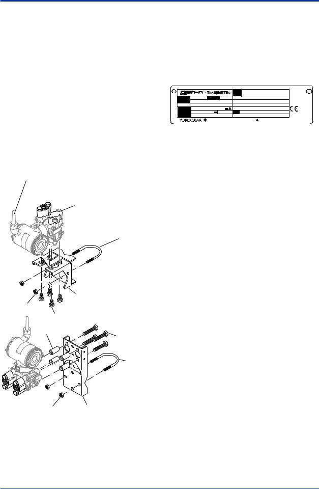
Also check that all transmitter mounting hardware shown in figure 2.1 is included. If the transmitter is ordered without the mounting bracket and the process connector, the transmitter mounting hardware will not be included.After checking the transmitter, carefully repack it in its box and keep it there until you are ready to install it.
Antenna The antenna is a detachable type when
Amplifier housing code 8 is selected, and no antenna is provided for Amplifier housing code 9.
Bolt


 Process connector


 Process connector gasket
U-bolt
|
Mounting bracket |
|
U-bolt nut |
(L type) |
|
|
|
|
|
Transmitter |
|
|
mounting bolt |
|
|
Spacer |
Transmitter |
|
|
|
|
|
mounting bolt |
|
|
U-bolt |
U-bolt nut |
Mounting bracket |
|
(Flat type) |
F0201.ai
Figure 2.1 Transmitter Mounting Hardware
2.1Model and Specifications Check
The model name and specifications are written on the name plate attached to the case.
|
CAL |
|
RNG |
MODEL |
STYLE |
SUFFIX |
|
SUPPLY |
mA DC |
V DC |
OUTPUT |
NO. |
|
MWP |
|
|
Made in Japan |
: Refer to USER'S MANUAL. |
TOKYO 180-8750 JAPAN |
|
F0202.ai
Figure 2.2 Name Plate
2.2Unpacking
Keep the transmitter in its original packaging to prevent it from being damaged during shipment. Do not unpack the transmitter until it reaches the installation site.
2.3Storage
The following precautions must be observed when storing the instrument, especially for a long period.
(a)Select a storage area which meets the following conditions:
•It is not exposed to rain or subject to water seepage/leaks.
•Vibration and shock are kept to a minimum.
•It has an ambient temperature and relative humidity within the following ranges.
Ambient temperature: –40 to 85°C
–30 to 80°C LCD visible range Relative humidity:
0% to 100% R.H.
Preferred temperature and humidity: approx. 25°C and 65% R.H.
(b)Whenstoringthetransmitter,repackitcarefullyin thepackagingthatitwasoriginallyshippedwith.
(c)If the transmitter has been used, thoroughly clean the chambers inside the cover flanges, so that there is no process fluid remaining inside. Before placing it in storage, also make sure that the pressure-detector is securely connected to the transmitter section.
(d)Preferably remove the batteries for storage. For maximum battery life, the storage temperature should not exceed 30°C.
IM 01C27B01-01EN
 NOTE
NOTE
When storing the instrument with a battery pack, it is recommended to put the instrument in Deep Sleep mode to conserve the batteries. For details on how to switch to Deep Sleep mode, refer to subsection 8.3.16 “Switching to Deep Sleep Mode”.
2.4Selecting the Installation Location
The transmitter is designed to withstand severe environmental conditions. However, to ensure that it will provide years of stable and accurate performance, take the following precautions when selecting the installation location.
(a) Wireless Communication
 NOTE
NOTE
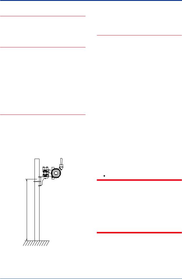
The installation location of this transmitter must meet the following conditions:
-Adjust the direction of the antenna to be in the upright position regardless of the orientation of this transmitter. See section 4 for adjusting the antenna.
-Install the transmitter at least 1.5m above the ground or floor.
1.5m or more
F0203.ai
- Ensure that there are no obstacles such as walls or pipes within a 30-cm radius of each antenna.
<2. Handling Cautions> |
2-2 |
-Confirm that each field wireless equipment compliant with ISA100.11a can see the antenna of other devices which locate within its own communication range. In the star topology network, the visibility to the antenna of gateway is a mandatory clause.
(b)AmbientTemperature
Avoid locations subject to wide temperature variations or a significant temperature gradient. If the location is exposed to radiant heat from plant equipment, provide adequate thermal insulation and/or ventilation.
(c)AmbientAtmosphere
Do not install the transmitter in a corrosive atmosphere. If this cannot be avoided, there must be adequate ventilation.
(d)Shock and Vibration
Although the transmitter is designed to be relatively resistant to shock and vibration, an installation site should be selected where this is kept to a minimum.
(e)Installation of Explosion-protectedTransmitters An explosion-protected transmitters is certified for installation in a hazardous area containing specific gas types. See subsection 2.8 “Installation of an Explosion-Protected Transmitters.”
2.5Pressure Connection
 WARNING
•Never loosen the process connector bolts when an instrument is installed in a process. The device is under pressure, and a loss of seal can result in a sudden and uncontrolled release of process fluid.
•When draining toxic process fluids that have condensed inside the pressure detector, take appropriate steps to prevent the contact of such fluids with the skin or eyes and the inhalation of vapors from these fluids.
IM 01C27B01-01EN
<2. Handling Cautions> |
2-3 |
|
|
The following precautions must be observed in order to safely operate the transmitter under pressure.
(a)Make sure that all the process connector bolts are tightened firmly.
(b)Makesurethattherearenoleaksintheimpulse piping.
(c)Never apply a pressure higher than the specified maximum working pressure.
2.6Restrictions on Use of Radio Transceivers
 IMPORTANT
Although the transmitter has been designed to resist high frequency electrical noise, if a radio transceiver is used near the transmitter or its external wiring, the transmitter may be affected by high frequency noise pickup.To test this, start out from a distance of several meters and slowly approach the transmitter with the transceiver while observing the measurement loop for noise effects. Thereafter use the transceiver outside the range where the noise effects were first observed.
2.7Insulation Resistance and Dielectric Strength Test
Since the transmitter has undergone insulation resistance and dielectric strength tests at the factory before shipment, normally these tests are not required. If the need arises to conduct these tests, heed the following:
(a)Do not perform such tests more frequently than is absolutely necessary. Even test voltages that do not cause visible damage to the insulation may degrade the insulation and reduce safety margins.
(b)Never apply a voltage exceeding 500 V DC (100 V DC with an internal lightning protector) for the insulation resistance test, nor a voltage exceeding 500 VAC (100 VAC with an internal lightning protector) for the dielectric strength test.
(c)The procedure for conducting these tests is as follows:
•Insulation Resistance Test
1)Remove the battery pack. See subsection 9.4.6 for details on how to remove it.
2)Short-circuit the battery connection terminals in the terminal box.
3)Turn OFF the insulation tester.Then connect the insulation tester plus (+) lead wire to the shorted battery connection terminals and the minus (–) leadwire to the grounding terminal.
4)Turn ON the insulation tester power and measure the insulation resistance.The voltage should be applied as briefly as possible to verify that the insulation resistance is at least 20 MΩ.
5)After completing the test and being very careful not to touch exposed conductors disconnect the insulation tester and connect a 100 kΩ resistor between the grounding terminal and the shortcircuiting battery connection terminals. Leave this resistor connected at least one second to discharge any static potential. Do not touch the terminals while it is discharging.
 NOTE
NOTE
When storing the instrument with a battery pack, it is recommended to put the instrument in Deep Sleep mode to conserve the batteries. For details on how to switch to Deep Sleep mode, refer to subsection 8.3.16 “Switching to Deep Sleep Mode”.
•Dielectric Strength Test
1)Remove the battery pack. See subsection 9.4.6 for details on how to remove it.
2)Short-circuit the battery connection terminals in the terminal box.
3)Turn OFF the dielectric strength tester.Then connect the tester between the shorted battery connection terminals and the grounding terminal. Be sure to connect the grounding lead of the dielectric strength tester to the ground terminal.
4)Set the current limit on the dielectric strength tester to 0.1 mA, then turn ON the power and gradually increase the test voltage from ‘0’to the specified voltage.
5)When the specified voltage is reached, hold it for one minute.
6)After completing this test, slowly decrease the voltage to avoid any voltage surges.
IM 01C27B01-01EN

<2. Handling Cautions> |
2-4 |
|
|
 NOTE
NOTE
When storing the instrument with a battery pack, it is recommended to put the instrument in Deep Sleep mode to conserve the batteries. For details on how to switch to Deep Sleep mode, refer to subsection 8.3.16 “Switching to Deep Sleep Mode”.
2.8Installation of an ExplosionProtected Instrument
If a customer makes a repair or modification to an intrinsically safe instrument and the instrument is not restored to its original condition, its intrinsically safe construction may be compromised and the instrument may be hazardous to operate. Please contactYokogawa before making any repair or modification to an instrument.
 CAUTION
This instrument has been tested and certified as being intrinsically safe. Please note that severe restrictions apply to this instrument’s construction, installation, external wiring, maintenance and repair.Afailure to abide by these restrictions could make the instrument a hazard to operate.
 WARNING
The battery pack may be replaced in a hazardous area.The battery pack has surface resistivity greater than 1G ohm and must be properly installed in the enclosure of the transmitter. Care must be taken during
transportation to and from the point of installation to prevent electrostatic charge build-up.
2.8.1 FMApproval
Caution for FM intrinsically safe type. (Following contents refer “DOC. No. IFM037-A20”)
Note 1. Model EJX Series Differential, gauge and absolute pressure transmitters with optional code /FS17 are applicable for use in hazardous locations.
•Applicable Standard: Class 3600, Class 3610, Class 3611, Class 3810, NEMA250, ANSI/ISA-60079-0,ANSI/ISA-60079-11
•Intrinsically Safe for Class I, Division 1, GroupsA, B, C & D, Class II, Division 1, Groups E, F & G and Class III, Division 1, Class I, Zone 0, in Hazardous Locations,AEx ia IIC
•Nonincendive for Class I, Division 2, Groups A, B, C & D, Class II, Division 2, Groups F & G and Class III, Division 1, Class I, Zone 2, Groups IIC, in Hazardous Locations.
•Enclosure:NEMA4X(Indoorsandoutdoors).
•Temperature Class:T4
•Ambient temperature: -50 to 70°C
Note 2. Installation
•Installation should be in accordance with ANSI/ISA-RP12.06.01 and the National Electric Code (NFPA70).
•Dust-tight conduit seal must be used when installed in a Class II, III, Group E, F and G environments.
•Note a warning label worded “SUBSTITUTION OF COMPONENTS MAY IMPAIR INTRINSIC SAFETY,” and “INSTALL INACCORDANCE WITH DOC. NO. IFM037-A20”.
IM 01C27B01-01EN
<2. Handling Cautions> |
2-5 |
|
|
[Installation Diagram]
Amplifier housing code 7
Hazardous Location
|
Transmitter |
|
|
|
|
|
|
|
Battery Pack |
|
|
[Intrinsically Safe] |
[Nonincendive] |
||
Class I, II, III, Division 1, |
Class I, II, Division 2, |
||
Groups A,B,C,D,E,F,G |
Groups A,B,C,D,F,G |
||
Class I, Zone 0 |
Class III, Division 1. |
||
in Hazardous (Classified) |
Class I, Zone 2, Group IIC, |
||
Locations |
in Hazardous (Classified) |
||
AEx ia IIC |
Locations |
||
Amplifier housing codes other than 7
Hazardous Location
Arrester |
|
Antenna |
(*1, *2) |
|
(*1) |
Antenna Connector
Transmitter
Battery Pack
*1: These apparatus are simple apparatus.
*2: Arrester may not be connected.
[Intrinsically Safe] |
[Nonincendive] |
Class I, II, III, Division 1, |
Class I, II, Division 2, |
Groups A,B,C,D,E,F,G |
Groups A,B,C,D,F,G |
Class I, Zone 0 |
Class III, Division 1. |
in Hazardous (Classified) |
Class I, Zone 2, Group IIC, |
Locations |
in Hazardous (Classified) |
AEx ia IIC |
Locations |
|
F0210.ai |
Note 3. Maintenance and Repair
•The instrument modification or parts replacement by other than authorized representative ofYokogawa Electric Corporation is prohibited and will void FM Approvals approval.
Note 4. Battery Pack
USE ONLYBATTERYPACKYOKOGAWA F9915MAOR F9915NS.
Note 5. Special Conditions for safe use POTENTIALELECTROSTATIC CHARGING HAZARD-SECURE DISTANCE OF 100MM FROMANTENNA.
DO NOTOPEN WHEN CLII, III, DIV 1,2 ATMOSPHERE IS PRESENT.
2.8.2 CSACertification
Caution for CSAIntrinsically safe type. (Following contents refer to “DOC No. ICS030”)
Note 1. Model EJX Series differential, gauge, and absolute pressure transmitters with optional code /CS17 are applicable for use in hazardous locations
Certificate: 2325443
•Applicable standard: CAN/CSA-C22.2 No.0, CAN/CSA-C22.2 No.0.4, C22.2 No.25, CAN/CSA-C22.2 No.94,
CAN/CSA-C22.2 No.157, C22.2 No.213, CAN/CSA-C22.2 No.61010-1, CAN/CSAC22.2 No.60079-0, CAN/CSA-E60079-11, IEC60529
•Ex ia IICT4
•Intrinsically Safe for Class I, Division 1, GroupsA, B, C & D, Class II, Division 1, Groups E, F & G, Class III, Division 1
•Nonincendive for Class I, Division2, GroupsA, B, C & D, Class II, Division2, Groups F & G, Class III, Division1
•Enclosure: IP66/IP67 andType 4X
•Temperature Code:T4
•AmbientTemperature: -50 to 70°C
•Max. ProcessTemp.: 120°C
Note 2. Installation
•Installation should be in accordance with Canadian Electrical Code Part I and Local Electrical Code.
•Do not alter drawing without authorization from CSA.
•The instrument modification or parts replacement by other than authorized representative ofYokogawa Electric Corporation is prohibited and will void Canadian Standards Intrinsically safe and nonincendive Certification.
IM 01C27B01-01EN
<2. Handling Cautions> |
2-6 |
|
|
[Installation Diagram]
Amplifier housing code 7
Hazardous Area
Transmitter
Battery Pack
[Intrinsically Safe] |
[Nonincendive] |
|||
Group IIC, Zone 0 |
Class I, II, Division 2, |
|||
Class I, II, III, Division 1, |
Groups A,B,C,D,F,G |
|||
Groups A,B,C,D,E,F,G |
Class III, Division 1 |
|||
Amplifier housing code 8 and 9 |
|
|||
Hazardous Area |
|
|||
|
|
Arrester |
Antenna |
|
|
|
(*1, *2) |
|
(*1) |
Antenna Connector
Transmitter
Battery Pack
*1: These apparatus are simple apparatus.
*2: Arrester may not be connected.
[Intrinsically Safe] |
[Nonincendive] |
Group IIC, Zone 0 |
Class I, II, Division 2, |
Class I, II, III, Division 1, |
Groups A,B,C,D,F,G |
Groups A,B,C,D,E,F,G |
Class III, Division 1 |
|
F0205.ai |
Note 3. Battery Pack
•Use onlyYOKOGAWAbattery pack F9915MAor F9915NS.
Note 4. Special Conditions for safe use
•Potential electrostatic charging hazard - secure distance of 100mm from antenna.
2.8.3 ATEX Certification
(1) Technical Data
Caution forATEX Intrinsically safe type.
Note 1. Model EJX Series pressure transmitters
with optional code /KS27 for potentially
explosive atmospheres:
•No. KEMA10ATEX0164 X
•Applicable Standard:
EN 60079-0:2009, EN 60079-11:2012, EN 60079-26:2007
•Type of Protection and Marking code: Ex ia IICT4 Ga
•Group: II
•Category: 1 G
•AmbientTemperature: –50°C to 70°C
•ProcessTemperature (Tp.): 120°C max.
•Enclosure: IP66/IP67
Note 2. Installation
•Installation should be in accordance with local installation requirements. (Refer to the Control Drawing)
[Control Drawing]
Amplifier housing code 7
Hazardous Area
Transmitter
Battery Pack
Amplifier housing code 8 and 9
Hazardous Area
Arrester |
|
Antenna |
(*1, *2) |
|
(*1) |
Antenna connector
Transmitter
Battery Pack
*1: These apparatus are simple apparatus. *2: Arrester may not be connected.
F0206.ai
Note 3. Battery Pack
•Use onlyYOKOGAWAbattery pack F9915MAor F9915NS.
Note 4. Special conditions for Safe Use
•In case the enclosure of the Pressure Transmitter is made of aluminum, if it is mounted in an area where the use of
category 1 G apparatus is required, it must be installed such, that, even in the event of rare incidents, ignition sources due to impact and friction sparks are excluded.
•For applications in explosive atmospheres caused by gases, vapors or mists and where category 1 G apparatus is required, electrostatic charges on the non-metallic parts of the PressureTransmitter shall be avoided.
 WARNING
Potential electrostatic charging hazard - secure distance of 100mm from antenna.
IM 01C27B01-01EN
<2. Handling Cautions> |
2-7 |
|
|
(2) Operation
 WARNING
Take care not to generate mechanical sparking when access to the instrument and peripheral devices in a hazardous location.
(3) Maintenance and repair
 WARNING
Theinstrumentmodificationorpartsreplacement by other than an authorized Representative of Yokogawa Electric Corporation is prohibited and will void the certification.
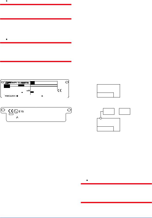
(4)Name Plate
•Name Plate
|
CAL |
|
RNG |
MODEL |
STYLE |
SUFFIX |
|
|
|
|
|
|
|
|
|
|
|
|
|
|
|
|
SUPPLY |
|
|
|
V DC |
|
|
|
|
|
|
|
|
|
OUTPUT |
|
mA DC |
|
|
|
|
NO. |
|
|
|
|
|
|
|
|
|
|
|||||||||
|
MWP |
|
|
|
|
|
|
|
|
|
|
|
|
|
|
|
|
Made in Japan |
|
|
: Refer to USER'S MANUAL. |
||||||
|
|
|
|
TOKYO 180-8750 JAPAN |
|
|
|
||||||
|
|
|
|
|
|
|
|
|
|
|
|
F0207.ai |
|
|
• Tag plate for intrinsically safe type |
||||||||||||
|
|
|
|
|
|
No. KEMA 10ATEX0164 X |
|
|
|
||||
KS27 |
|
|
Ex ia IIC T4 Ga |
|
|
|
|||||||
|
|
ENCLOSURE: IP66/IP67 |
|
|
|
||||||||
*3 |
|
|
|
|
Tamb.: -50 TO 70°C |
|
|
|
|||||
|
|
|
|
MAX PROCESS TEMP.: 120°C |
|||||||||
|
WARNING |
POTENTIAL ELECTROSTATIC CHARGING HAZARD - SECURE DISTANCE |
|||||||||||
|
OF 100MM FROM ANTENNA. |
|
|
|
|||||||||
USE ONLY BATTERY PACK YOKOGAWA F9915MA OR F9915NS.
POTENTIAL ELECTROSTATIC CHARGING HAZARD - SEE USER'S MANUAL.
F0208.ai
MODEL: Specified model code.
STYLE: Style code.
SUFFIX: Specified suffix code.
SUPPLY: Supply voltage.
OUTPUT: Output signal.
MWP: Maximum working pressure.
CALRNG: Specified calibration range.
NO.: Serial number and year of production*1.
TOKYO 180-8750 JAPAN:
The manufacturer name and the address*2.
*1: |
The first digit in the final three numbers of the serial |
|
|
number appearing after “NO.” on the nameplate indicates |
|
|
the year of production.The following is an example of a |
|
|
serial number for a product that was produced in 2010: |
|
|
91K819857 |
032 |
|
|
↑ |
|
The year 2010 |
|
*2: |
“180-8750” is a zip code which represents the following |
|
|
address. |
|
|
2-9-32 Nakacho, Musashino-shi,Tokyo Japan |
|
*3: |
The identification number of Notified Body. |
|
2.8.4 IECEx Certification
Caution for IECEx Intrinsically safe type.
Note 1. Model EJX Series pressure transmitters
with optional code /SS27 for potentially
explosive atmospheres:
•No. IECEx KEM 10.0074X
•Applicable Standard:
IEC 60079-0:2011, IEC 60079-11:2011, IEC 60079-26:2006
•Type of Protection and Marking code: Ex ia IICT4 Ga
•AmbientTemperature: –50°C to 70°C
•ProcessTemperature (Tp.): 120°C max.
•Enclosure: IP66/IP67
Note 2. Installation
•Installation should be in accordance with local installation requirements.
(Refer to the Control Drawing)
[Control Drawing]
Amplifier housing code 7
Hazardous Area
Transmitter
Battery Pack
Amplifier housing code 8 and 9
Hazardous Area
Arrester |
|
Antenna |
(*1, *2) |
|
(*1) |
Antenna connector
Transmitter
Battery Pack
*1: These apparatus are simple apparatus. *2: Arrester may not be connected.
F0209.ai
Note 3. Maintenance and Repair
•The instrument modification or parts replacement by other than authorized representative ofYokogawa Electric Corporation is prohibited and will void IECEx Intrinsically safe Certification.
 WARNING
Theinstrumentmodificationorpartsreplacement by other than an authorized Representative of Yokogawa Electric Corporation is prohibited and will void the certification.
IM 01C27B01-01EN

<2. Handling Cautions> |
2-8 |
Note 4. Battery Pack
•Use onlyYOKOGAWAbattery pack F9915MAor F9915NS.
Note 5. Special conditions for Safe Use
•In case the enclosure of the Pressure Transmitter is made of aluminum, if it is mounted in an area where the use of
apparatus of equipment protection level Ga is required, it must be installed such, that, even in the event of rare incidents, ignition sources due to impact and friction sparks are excluded.
•For applications in explosive atmospheres caused by gases, vapors or mists and mounted in an area where the use of apparatus of equipment protection level Ga is required, electrostatic charges on the nonmetallic parts of the PressureTransmitter shall be avoided.
 WARNING
•Potential electrostatic charging hazard - secure distance of 100mm from antenna.
•Take care not to generate mechanical sparking when access to the instrument and peripheral devices in a hazardous location.
2.9EMC Conformity Standards
EN61326-1 ClassA,Table 2 (For use in industrial locations), EN61326-2-3
 CAUTION
This instrument is a ClassAproduct, and it is designed for use in the industrial environment. Please use this instrument in the industrial environment only.
2.10Pressure Equipment Directive (PED) 
(1) General
•EJX Series pressure transmitters are categorized as pressure accessories under the vessel section of directive 97/23/EC, which corresponds toArticle 3, Paragraph 3 of PED, denoted as Sound Engineering Practice (SEP).
•EJX110B-MS, EJX110B-HS, EJX110B-VS, EJX510B-D, and EJX530B-D can be used above 200 bar and therefore considered as a part of a pressure retaining vessel where category III, Module H applies.These models with option code /PE3 conform to that category.
(2) Technical Data
•Models without /PE3
Article 3, Paragraph 3 of PED, denoted as Sound Engineering Practice (SEP).
•Models with /PE3 Module: H
Type of Equipment: PressureAccessory-Vessel Type of fluid: Liquid and Gas
Group of fluid: 1 and 2
Model |
Capsule |
PS |
V(L) |
PS·V |
|
Category*2 |
|
code |
(bar)*1 |
(bar·L) |
|
||||
|
|
F, L |
160 |
0.01 |
1.6 |
|
Article 3, |
EJX110B |
|
Paragraph 3 |
|||||
M, H, V |
250 |
0.01 |
2.5 |
|
|||
|
|
|
(SEP) |
||||
EJX110B |
|
|
|
|
|
|
|
with code |
M, H, V |
250 |
0.01 |
2.5 |
|
III |
|
/PE3 |
|
|
|
|
|
|
|
|
|
|
|
|
|
|
Article 3, |
EJX310B |
L, M,A, B |
160 |
0.01 |
1.6 |
|
Paragraph 3 |
|
|
|
|
|
|
|
|
(SEP) |
|
|
|
|
|
|
|
Article 3, |
EJX430B |
H,A, B |
160 |
0.01 |
1.6 |
|
Paragraph 3 |
|
|
|
|
|
|
|
|
(SEP) |
|
|
A, B, C |
100 |
0.1 |
10 |
|
Article 3, |
EJX510B |
|
Paragraph 3 |
|||||
D |
700 |
0.1 |
70 |
|
|||
|
|
|
(SEP) |
||||
EJX510B |
|
|
|
|
|
|
|
with code |
D |
700 |
0.1 |
70 |
|
III |
|
/PE3 |
|
|
|
|
|
|
|
|
|
A, B, C |
100 |
0.1 |
10 |
|
Article 3, |
EJX530B |
|
Paragraph 3 |
|||||
D |
700 |
0.1 |
70 |
|
|||
|
|
|
(SEP) |
||||
EJX530B |
|
|
|
|
|
|
|
with code |
D |
700 |
0.1 |
70 |
|
III |
|
/PE3 |
|
|
|
|
|
|
|
*1: |
PS is maximum allowable pressure for vessel itself. |
||||||
*2: |
Referred toTable 1 covered byANNEX II of EC Directive |
||||||
|
on Pressure Equipment Directive 97/23/EC |
|
|||||
IM 01C27B01-01EN

<2. Handling Cautions> |
2-9 |
(3) Operation
 CAUTION
•The temperature and pressure of fluid should be maintained at levels that are consistent with normal operating conditions.
•The ambient temperature should be maintained at a level that is consistent with normal operating conditions.
•Please take care to prevent water hammer and the like from inducing excessive pressures in pipes and valves. If phenomena are likely, install a safety valve or take some other appropriate measure to prevent pressure from exceeding PS.
•Take appropriate measures at the device or system level to protect transmitters if they are to be operated near an external heat source.
2.11 Low Voltage Directive
Applicable standard: EN61010-1, EN61010-2-030
(1) Pollution Degree 2
"Pollution degree" describes the degree to which a solid, liquid, or gas which deteriorates dielectric strength or surface resistivity is adhering. " 2 " applies to normal indoor atmosphere. Normally, only non-conductive pollution occurs. Occasionally, however, temporary conductivity caused by condensation must be expected.
(2)Installation Category I
(Anticipated transient overvoltage 330 V)
"Overvoltage category (Installation category)" describes a number which defines a transient overvoltage condition. It implies the regulation for impulse withstand voltage. " I " applies to electrical equipment which is supplied from the circuit when appropriate transient overvoltage control means (interfaces) are provided.
2.12Regulatory Compliance for Radio and Telecommunication
Please confirm that a installation region fulfils a standards, require additional regulatory information and approvals, contact to Yokogawa Electric Corporation.
2.12.1 Radio and Telecommunications
Terminal Equipment Directive (R&TTE) 


We,Yokogawa Electric Corporation hereby declare that this equipment, model EJX-Lseries is in compliance with the essential requirements and other relevant provisions of Directive 1999/5/EC.
The CE declaration of conformity for R&TTE for this product can be found at http://www. yokogawa.com/fld/
2.12.2 FCC compliance
This equipment contains transmitter module FCC ID: SGJ-WFC001.
This device complies with Part 15 of FCC Rules. Operation is subject to the following two conditions: (1) this device may not cause interference, and (2) this device must accept any interference, including interference that may cause undesired operation of this device.
Co-located:
This transmitter must not be co-located or operated in conjunction with any other antenna or transmitter.
FCC WARNING:
Changes or modifications not expressly approved by the party responsible for compliance could void the user’s authority to operate the equipment.
IM 01C27B01-01EN

<2. Handling Cautions> |
2-10 |
|
|
 NOTE
NOTE
This equipment has been tested and found to comply with the limits for a ClassAdigital device, pursuant to part 15 of the FCC Rules.
These limits are designed to provide reasonable protection against harmful interference when the equipment is operated in a commercial environment.
This equipment generates, uses, and can radiate radio frequency energy and, if not installed
and used in accordance with the instruction manual,may cause harmful interference to radio communications. Operation of this equipment in a residential area is likely to cause harmful interference in which case the user will be required to correct the interference at his own expense.
2.12.3 Industry Canada (IC) compliance
This equipment contains transmitter module IC:
8999A-WIC001.
This ClassAdigital apparatus complies with
Canadian ICES-003.
This device complies with Industry Canada license-exempt RSS standard(s). Operation is subject to the following two conditions: (1) this device may not cause interference, and (2) this device must accept any interference, including interference that may cause undesired, operation of the device.
Under Industry Canada regulations, this radio transmitter may only operate using an antenna of a type and maximum (or lesser) gain approved for the transmitter by Industry Canada.To reduce potential radio interference to other users, the antenna type and its gain should be so chosen that the equivalent isotropically radiated power (e.i.r.p.) is not more than that necessary for successful communication.
This radio transmitter IC Number 8999A-WIC001 has been approved by Industry Canada to operate with the antenna types listed below with the maximum permissible gain and required antenna impedance for each antenna type indicated.Antenna types not included in this list, having a gain greater than the maximum gain indicated for that type, are strictly prohibited for use with this device.
Antenna type: |
Gain: |
COLLINEAR |
9 dBi, 50 Ω |
Sleeve |
2.14 dBi, 50 Ω |
French:
Cet appareil numérique de la classeAest conforme à la norme NMB-003 du Canada.
Le présent appareil est conforme aux CNR d’Industrie Canada applicables aux appareils radio exempts de licence. L’exploitation est autorisée aux deux conditions suivantes : (1) l’appareil ne doit pas produire de brouillage, et (2) l’utilisateur de l’appareil doit accepter tout brouillage radioélectrique subi, même si le brouillage est susceptible d’en compromettre le fonctionnement.
Conformément à la réglementation d’Industrie Canada, le présent émetteur radio peut fonctionner avec une antenne d’un type et d’un gain maximal (ou inférieur) approuvé pour l’émetteur par Industrie Canada. Dans le but de réduire les risques de brouillage radioélectrique
àl’intention des autres utilisateurs, il faut choisir le type d’antenne et son gain de sorte que
la puissance isotrope rayonnée équivalente (p.i.r.e.) ne dépasse pas l’intensité nécessaire
àl’établissement d’une communication satisfaisante.
Le présent émetteur radio IC Number 8999A-WIC001 a été approuvé par Industrie Canada pour fonctionner avec les types d’antenne énumérés ci-dessous et ayant un gain admissible maximal et l’impédance
requise pour chaque type d’antenne. Les types d’antenne non inclus dans cette liste, ou dont le gain est supérieur au gain maximal indiqué, sont strictement interdits pour l’exploitation de l’émetteur.
Antenne type:
COLLINEAR Sleeve
IM 01C27B01-01EN
<3. Component Names> |
3-1 |
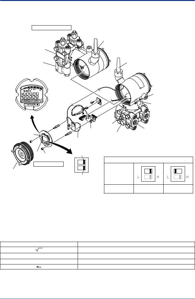
3.Component Names
Vertical impulse pipimg type
Preccure-detector section
Cover flange
Process connector (Note1)
Integral indicator
Slide
switch screw
Transmitter section
Amplifier Cover
Terminal box cover
Horizontal impulse piping type
Antenna (Note 4)
Ground terminal
|
|
|
|
Zero-adjustment |
|
|
|
|
|
|
screw |
|
|
|
|
Vent plug |
|
Process |
|
|
|
CPU assembly |
|
|
|
||
|
|
connction |
|
|
||
|
|
Drain plug |
|
|
|
|
|
|
|
|
|
|
|
RF assembly |
|
|
|
|
|
|
|
Write protection switch |
|
|
|
|
|
D |
E WR |
Hardware write protection switch (WR) |
|
|||
|
|
|
|
|
||
|
|
Write protection |
D |
E |
D |
E |
|
|
Switch Position |
||||
|
Not in use |
L |
H |
L |
H |
|
|
(Note 2) |
|||||
|
|
Write protection |
|
NO |
YES (Note 3) |
|
|
|
(Write enabled) |
(Write disabled) |
|||
|
|
|
||||
F0301.ai
Note 1: Aprocess connector will not be applied for lower side of EJX430B and EJX310B.
Note 2: Set the switch as shown in the figure above to set the write protection.The hardware write protection switch is set to E side. Set
to H side for the switch of not-in-use.
Note 3: When the switch is D side (write protection setting), provisioning is acceptable. For details of provisioning, refer to section 7.4
“ Connecting to the Field Wireless Network ”.
Note 4: The detachable antenna is applied when the amplifier housing code 7 or 8 is specified.
Figure 3.1 Component Names
Table 3.1 Display Symbol
Display Symbol Meaning of Display Symbol
Display mode is ‘square root’. (Display is not lit when ‘linear’mode.)
▲The output signal being zero-adjusted is increasing.
▼The output signal being zero-adjusted is decreasing.
Write protect function is enabled.
IM 01C27B01-01EN
<4. Installation> |
4-1 |
4.Installation
4.1Precautions
Before installing the transmitter, read the cautionary notes in section 2.4, “Selecting the Installation Location.” For additional information on the ambient conditions allowed at the installation location, refer to subsection 11.1 “Standard Specifications.”
 NOTE
NOTE
To connect this transmitter to the Field Wireless Network, information for connecting to the field wireless devices needs to be set beforehand. Refer to 7.4 “Connecting to the Field Wireless Network.”
 IMPORTANT
•When welding piping during construction, take care not to allow welding currents to flow through the transmitter.
•Do not step on this instrument after installation.
•For the EJX430B, the atmospheric opening is located on the low pressure side cover flange.Take care do not enter rain into the opening.The opening must not face upward. See section 11.4, “Dimensions,” for the location of the opening.
4.2Mounting
■The transmitter is shipped with the process connection, according to the ordering specifications.To change the orientation of the process connections, refer to section 4.3.
■With differential pressure transmitters, the distance between the impulse piping
connection ports is usually 54 mm (figure 4.1). By changing the orientation of the process connector, the dimension can be changed to 51 mm or 57 mm.
■The transmitter can be mounted on a nominal 50 mm (2-inch) pipe using the mounting bracket supplied, as shown in figure 4.2 and 4.3.
The transmitter can be mounted on either a horizontal or a vertical pipe.
■When mounting the bracket on the transmitter, tighten the (four) bolts that hold the transmitter with a torque of approximately 39 N·m {4kgf·m}.
57 mm 54 mm 51 mm
F0401.ai
Figure 4.1 Process Connector Impulse Piping Connection Distances for Differential Pressure Transmitters
 CAUTION
When the suffix code of the mounting bracket is “B,” make sure to put the spacer between the bracket and transmitter as shown in Figure 4.2.
IM 01C27B01-01EN
<4. Installation> |
4-2 |
|
|
Horizontal pipe mounting
Spacer
Transmitter mounting bolt
|
50 mm (2-inch) |
|
pipe |
U-bolt nut |
|
Mounting bracket |
U-bolt |
|
|
Vertical pipe mounting |
|
Spacer
Transmitter
mounting bolt


 50 mm (2-inch)


 pipe
pipe
U-bolt nut |
U-bolt |
Mounting bracket
F0402.ai
Figure 4.2 Transmitter Mounting (Horizontal
Impulse Piping Type)
Vertical pipe mounting (Process connector upside)
Mounting bracket


 50 mm (2-inch) pipe U-bolt nut


U-bolt
Transmitter mounting bolt
Vertical pipe mounting (Process connector downside)
Transmitter

 mounting bolt
Mounting bracket


 50 mm (2-inch) pipe U-bolt nut


 U-bolt
F0403.ai
Figure 4.3 Transmitter Mounting (Vertical Impulse
Piping Type)
IM 01C27B01-01EN
<4. Installation> |
4-3 |
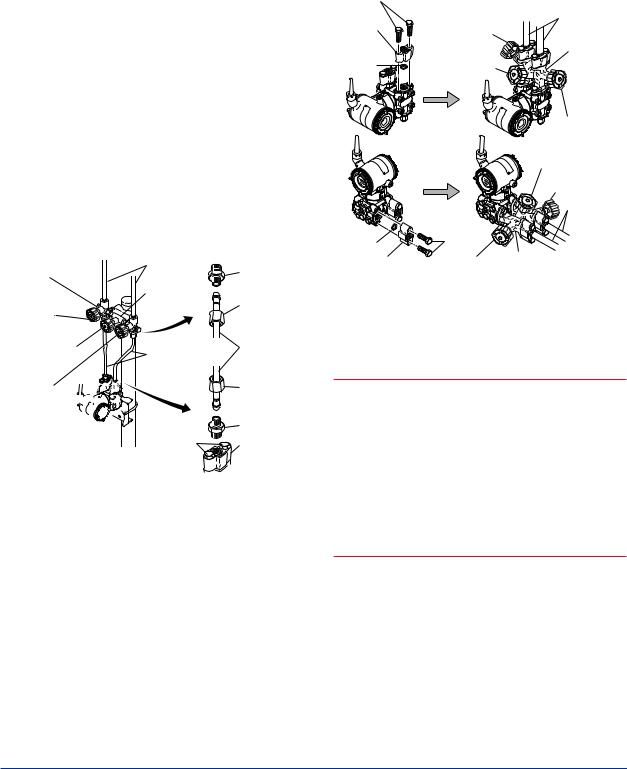
4.3Changing the Process Connection
The transmitter is shipped with the process connection specified at the time of ordering.To change the process connection, the drain (vent) plug must be repositioned.
To reposition a drain (vent) plug, refer to Figure 4.4 and use a wrench slowly and gently to unscrew it.Then, remove and remount it on the opposite side. Wrap sealing tape around the drain (vent) plug threads (*1 in the figure below), and apply a lubricant to the threads of the drain (vent) screw(s) (*2 below).To tighten the drain (vent) plugs, apply a torque of 34 to 39 N·m (3.5 to 4 kgf·m). Process connector bolts are to be tightened uniformly to a torque shown in table 4.1.
Table 4.1 |
Torque |
|
|
|
EJX110B |
Model |
|
EJX310B |
Torque(N·m) |
|
EJX430B |
|
39 to 49 {4 to 5} |
|
{kgf·m} |
|
|
|
|
|
Vertical impulse piping type |
||
|
Bolt |
|
Process connector |
gasket |
|
|
||


 1
1
Drain/vent plug 

 2
2
Horizontal impulse piping type
Note: For a horizontal impulse
piping type, moving the
process connectors from
the front side to the back
cannot be made.
F0404.ai
Figure 4.4 Changing Process Connection
4.4Swapping the High/Lowpressure Side Connection
 IMPORTANT
This section is applicable only for EJX110B differential transmitters, and not applicable for gauge or absolute pressure transmitters.
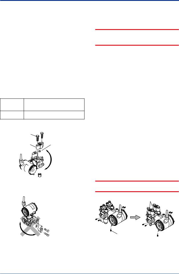
4.4.1Rotating Pressure-detector Section 180°
This procedure can be applied only to a transmitter with a vertical impulse piping type.
The procedure below can be used to turn the pressure detector assembly 180°. Perform this operation in a maintenance shop with the
necessary tools laid out and ready for use, and then install the transmitter in the field after making the change.
1)Use anAllen wrench (JIS B4648, nominal 2.5 mm) to remove the five setscrews at the joint between the pressure-detector section and transmitter section.
2)Leaving the transmitter section in position, rotate the pressure-detector section 180°.
3)Tighten the five setscrews to fix the pressuredetector section and transmitter section together (at a torque of 1.5 N·m). Reposition the process connector and drain
(vent) plugs to the opposite side as described in subsection 4.3.
 IMPORTANT
Do not rotate the transmitter section more than above limit.
Process connector
|
Setscrew |
Before |
After rotating 180° |
|
F0405.ai |
Figure 4.5 Before andAfter Modification
IM 01C27B01-01EN
<4. Installation> |
4-4 |
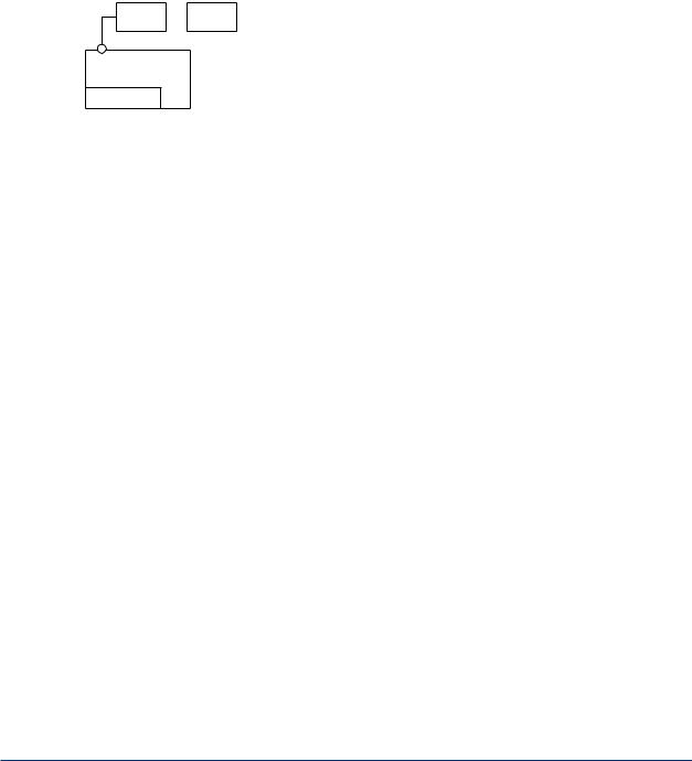
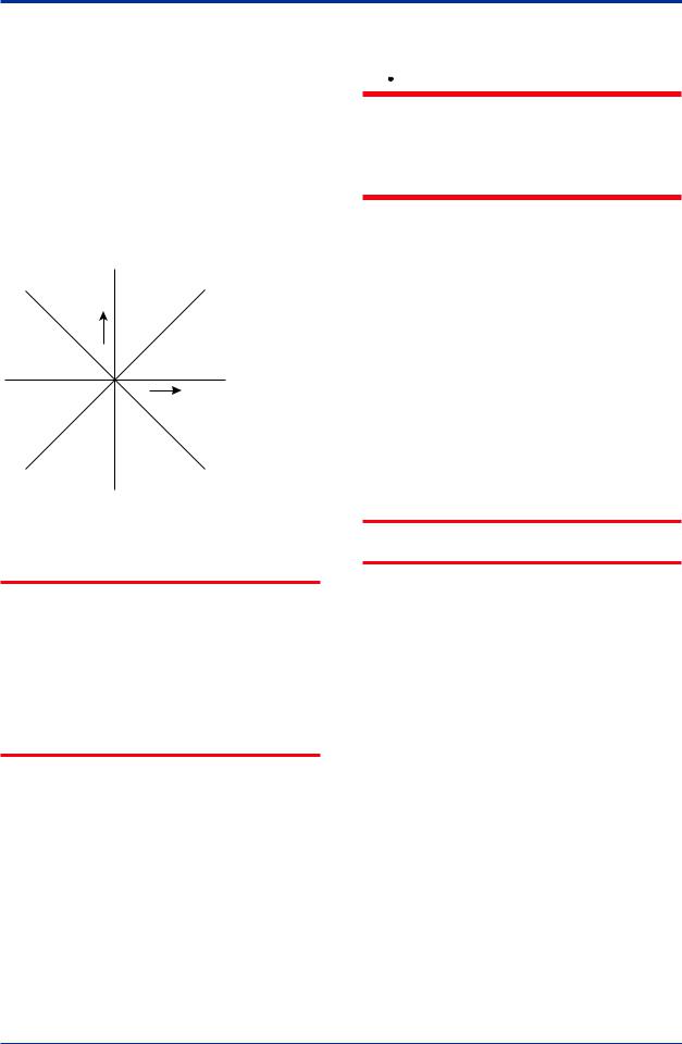
4.4.2 Using the Configuration Tool
This method is applicable only to the Model EJX110B.
With a configuration tool, you can change which process connection is used as the high-pressure side without mechanically rotating the pressuredetector section 180 as described in subsection 4.4.1.Tochange,callupthe‘H/L_SWAP’parameter and select REVERSE (right side: low pressure; left side: high pressure) or select NORMALto change back to normal (right side: high pressure; left side: low pressure).
NORMAL |
Output |
Input |
REVERSE |
F0406.ai
Figure 4.6 Input/Output Relationship
 IMPORTANT
Since the H/Llabel plate on the capsule assembly will remain unchanged, use this function only when you cannot switch the impulse piping. If the ‘H/L_SWAP’parameter setting is changed, the input/output relationship is reversed as shown in Figure 4.6; be sure this is understood by all.After reversing the setting, modify the H/Llabel plate to clearly indicate this change.
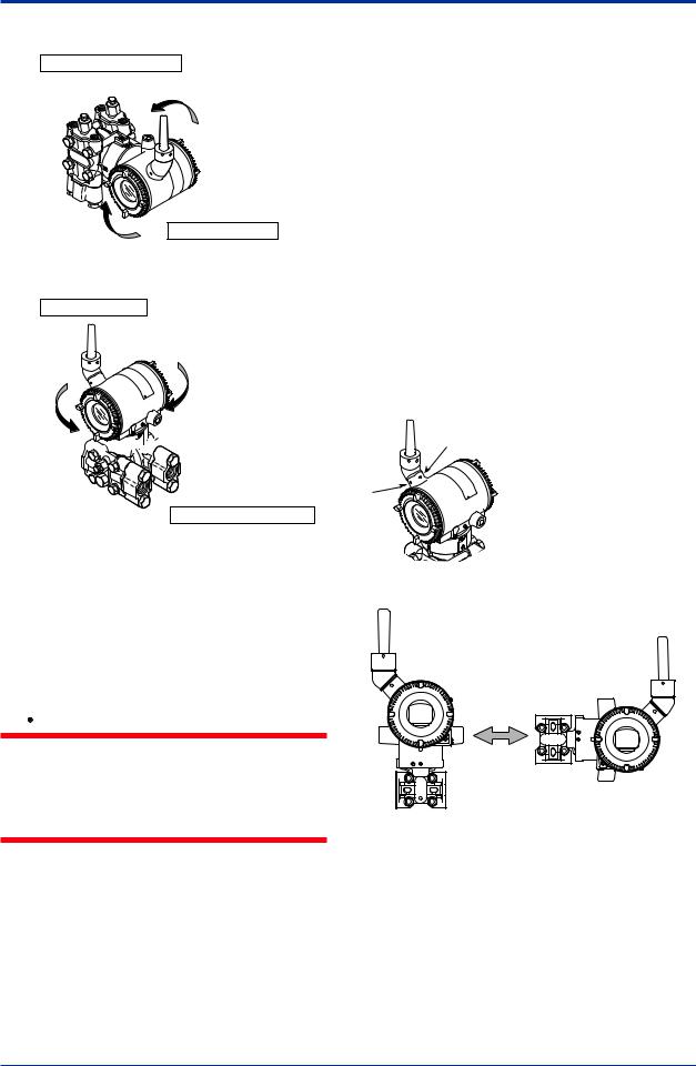
4.5Rotating Transmitter Section
 WARNING
Intrinsic safe type transmitters must be, as a rule, do not rotate transmitter section if it is powered. In case you need to rotate when the transmitter is powered, using gas detector and confirm no existence of explosive gas before rotating.
The transmitter section can be rotated approximately 360° (180° to either direction or 360° to one direction from the original position at shipment, depending on the configuration of the instrument.) It can be fixed at any angle within above range.
1)Remove the five setscrews that fasten the transmitter section and capsule assembly, using theAllen wrench.
2)Rotate the transmitter section slowly and stop it at designated position.
3)Tighten the five setscrews to a torque of 1.5 N·m.
 IMPORTANT
Do not rotate the transmitter section more than the above limit.
IM 01C27B01-01EN
<4. Installation> |
4-5 |
Vertical impulse piping type
Pressure-detector section
Rotate 0 to ±180° segments
Transmitter section
Horizontal impulse piping type
Transmitter section
Rotate 0 to ±180° segments


 Zero-adjustment screw
Pressure-detector section
F0407.ai
Figure 4.7 Rotating Transmitter Section (Left Side
High Pressure Type)
4.6Changing the Direction of Integral Indicator
 WARNING
Intrinsic safe type transmitters must be, as a rule, remove a battery pack in non-hazardous area before open/close theAmplifier Cover or disassembling and reassembling the Integral Indicator.
An integral indicator can be rotated in four positions at 90°. Follow the instructions in section 9.4.1 for removing and attaching the integral indicator.
4.7Changing the direction of the antenna
Adjust the direction of the antenna to be in the upright position. Figure4.8 shows factory setup antenna position. If the transmitter is installed to vertical impulse piping, follow the procedure below and change the antenna position.
1)Loosen the two mounting screws at the bottom of the antenna by using a 2.5 mmAllen wrench (see Figure 4.8).
The screws might come off and be lost if loosened too much; loosen the screws by about three rotations.
2)Press forward and down 90 degrees by rotating the axis at the bottom of the antenna.
3)Tighten the two screws to a torque of 1.5 N·m by using a torque wrench. When doing this, be careful not leave a gap between the antenna and housing.
F0408.ai
Figure 4.8 Mounting Screw Position
F0409.ai
Figure 4.9 AdjustingAntenna Position
IM 01C27B01-01EN
<5. Installing Impulse Piping> |
5-1 |
5.Installing Impulse Piping
5.1Impulse Piping Installation Precautions
The impulse piping that connects the process outputs to the transmitter must convey the process pressure accurately. If, for example, gas collects in a liquid-filled impulse line, or the drain for a gas-filled impulse line becomes plugged, it will not convey the pressure accurately. Since this will cause errors in the measurement output, select the proper piping method for the process fluid (gas, liquid, or steam). Pay careful attention to the following points when routing the impulse piping and connecting the impulse piping to a transmitter.
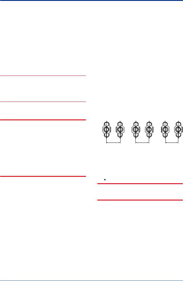
5.1.1Connecting Impulse Piping to a Transmitter
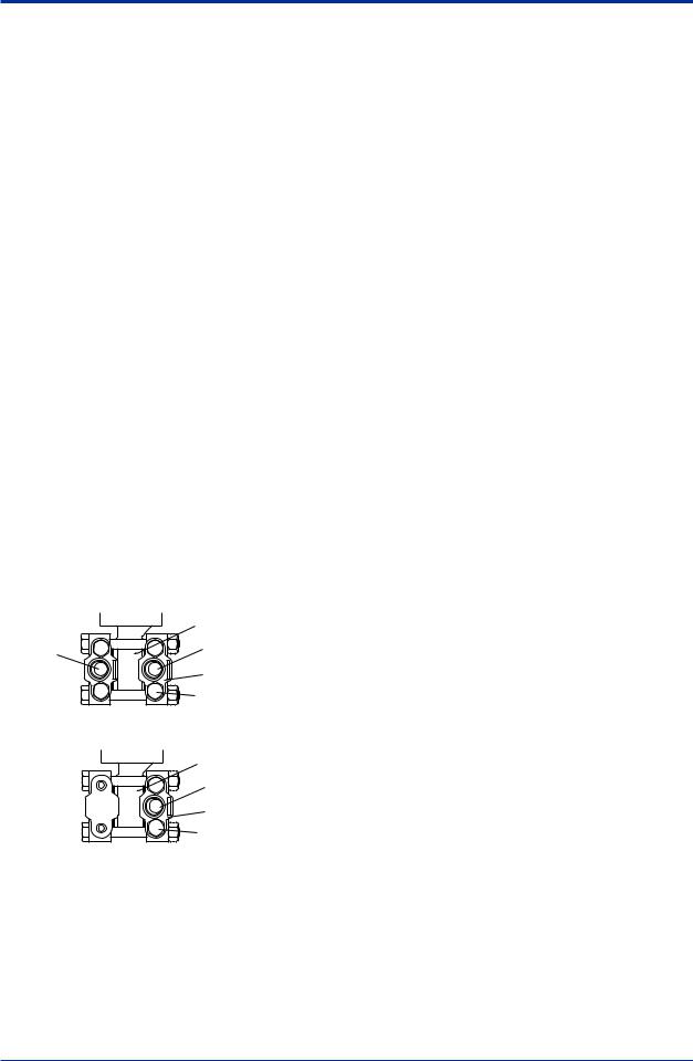
(1)Check the High and Low Pressure Connections on the Transmitter (Figure 5.1)
Symbols “H” and “L” have been placed on the capsule assembly to indicate high and low pressure side. With differential pressure transmitters, connect the high pressure side impulse line to the “H” side, and the low pressure side impulse line to the “L” side.
Differential Pressure Transmitter
|
“H” and “L” are shown |
Process |
Process connection |
connection |
Process connector |
|
|
|
Bolt |
Gauge/Absolute Pressure Transmitters |
|
|
“H” and “L” are shown |
|
Process connection |
|
Process connector |
|
Bolt |
|
F0501.ai |
Figure 5.1 “H” and “L” Symbols on a Capsule
Assembly
(2)Changing the Process Connector Piping Connections (Figure 4.1) (for differential pressure transmitters)
The impulse piping connection distances can be changed between 51 mm, 54 mm and 57 mm by changing the orientation of the process connectors. This is convenient for aligning an impulse line with a process connectors.
(3)Tightening the Process Connector Mounting Bolts
After connecting an impulse line, tighten the process connector mounting bolts uniformly. (Apply a torque of 39~49N·m {4~5kgf·m})
(4)Removing the Impulse Piping Connecting Port Dustproof Cap
The impulse piping and a 3-valve manifold connecting port on the transmitter is covered with a plastic cap to keep out dust.This cap must be removed before connecting the line. (Be careful not to damage the threads when removing this cap. Never insert a screwdriver or other tool between the cap and port threads to remove the cap.)
(5)Connecting the Transmitter and 3- Valve Manifold (for differential pressure transmitters)
A3-valve manifold consists of two stop valves to block process pressure and an equalizing valve to equalize the pressures on the high and low pressure sides of the transmitter. Such a manifold makes it easier to disconnect the transmitter from the impulse piping, and is convenient when adjusting the transmitter zero point.
There are two 3-valve manifold types: the pipemounting type and the direct-mounting type; care should be taken with respect to the following points when connecting the manifold to the transmitter.
IM 01C27B01-01EN
<5. Installing Impulse Piping> |
5-2 |
|
|
Pipe-Mounting Type 3-Valve Manifold (Figure 5.2)
1)Screw nipples into the connection ports on the transmitter side of the 3-valve manifold, and into the impulse piping connecting ports on the process connectors. (To maintain proper sealing, wind sealing tape around the nipple threads.)
2)Mount the 3-valve manifold on the 50 mm (2- inch) pipe by fastening a U-bolt to its mounting bracket.Tighten the U-bolt nuts only lightly at this time.
3)Install the pipe assemblies between the 3-valve manifold and the process connectors and lightly tightentheballheadlocknuts.(Theball-shaped ends of the pipes must be handled carefully, since they will not seal properly if the ball surface is scratched or otherwise damaged.)
4)Now tighten the nuts and bolts securely in the following sequence:
Process connector bolts → transmitter-end ball head lock nuts → 3-valve manifold ball head lock nuts → 3-valve manifold mounting bracket U-bolt nuts
Vent plug |
Impulse |
Nipple |
piping |
||
(optional) |
3-valve |
|
|
|
|
Stop valve |
manifold |
Ball head |
|
lock nut |
|
(low pressure side) |
|
|
Equalizing valve |
Pipe assembly |
Pipe assembly |
|
||
(balancing) |
|
|
Stop valve 


 (high pressure


 side)
side) 


50 mm (2-inch) pipe 
|
Ball head |
|
lock nut |
|
Nipple |
Process |
Process |
connector |
connector |
bolts |
F0502.ai |
|
Figure 5.2 3-Valve Manifold (Pipe-Mounting Type)
Direct-Mounting Type 3-Valve Manifold (Figure 5.3)
1)Mount the 3-valve manifold on the transmitter. (When mounting, use the two gaskets and the four bolts provided with the 3-valve manifold. Tighten the bolts evenly.)
2)Mount the process connectors and gaskets on the top of the 3-valve manifold (the side on which the impulse piping will be connected).
Bolts |
Stop valve |
|
Impulse |
|
|
||
Process |
(low pressure side) |
piping |
|
connector |
|
|
3-valve |
|
|
|
|
Gasket |
Equalizing |
|
manifold |
|
valve |
|
|
|
|
|
Stop valve |
|
|
|
(high pressure side) |
|
|
|
Equalizing valve |
|
|
|
Stop valve |
|
|
|
(high pressure side) |
|
(high |
|
Impulse |
|
pressure side) |
|
piping |
Gasket |
Bolts |
|
|
|
|
|
|
Process |
Stop valve |
3-valve |
|
connector |
|
|
|
(low pressure side) manifold |
|||
|
|
|
F0503.ai |
Figure 5.3 3-Valve Manifold (Direct-Mounting
Type)
 NOTE
NOTE
Aftercompletingtheconnectionofthetransmitter and 3-valve manifold, be sure to CLOSE the low pressure and high pressure stop valves, OPEN the equalizing valve, and leave the manifold with the equalizing valve OPEN.
You must do this in order to avoid overloading the transmitter from either the high or the low pressure side when beginning operation.
This instruction must also be followed as part of the startup procedure (chapter 7.)
IM 01C27B01-01EN
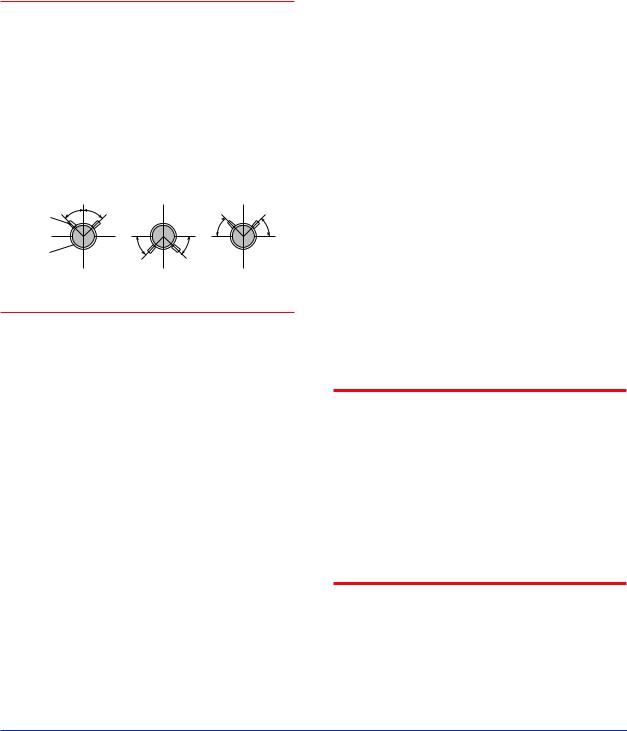
<5. Installing Impulse Piping> |
5-3 |
|
|
5.1.2 Routing the Impulse Piping
(1) Process Pressure TapAngles
If condensate, gas, sediment or other extraneous material in the process piping gets into the impulse piping, pressure measurement errors may result.To prevent such problems, the process pressure taps must be angled as shown in figure 5.4 according to the kind of fluid being measured.
 NOTE
NOTE
•If the process fluid is a gas, the taps must be vertical or within 45° either side of vertical.
•If the process fluid is a liquid, the taps must be horizontal or below horizontal, but not more than 45° below horizontal.
•If the process fluid is steam or other condensing vapor, the taps must be horizontal or above horizontal, but not more than 45° above horizontal.
|
[Gas] |
[Liquid] |
|
[Steam] |
Pressure |
45° 45° |
|
45° |
45° |
taps |
|
|
||
Process |
|
45° |
45° |
|
piping |
|
|
|
|
|
|
|
|
F0504.ai |
Figure 5.4 Process Pressure TapAngle
(For Horizontal Piping)
(2)Position of Process Pressure Taps and Transmitter
If condensate (or gas) accumulates in the impulse piping, it should be removed periodically by opening the drain (or vent) plugs. However, this will generate a transient disturbance in the pressure measurement, and therefore it is necessary to position the taps and route the impulse piping so that any extraneous liquid or gas generated in the leadlines returns naturally to the process piping.
•If the process fluid is a gas, then as a rule the transmitter must be located higher than the process pressure taps.
•If the process fluid is a liquid or steam, then as a rule the transmitter must be located lower than the process pressure taps.
(3) Impulse Piping Slope
The impulse piping must be routed with only an upward or downward slope. Even for horizontal routing, the impulse piping should have a slope of at least 1/10 to prevent condensate (or gases) from accumulating in the pipes.
(4)Temperature Difference Between Impulse Lines (for differential pressure transmitters)
If there is a temperature difference between the high and low impulse lines, the density difference of the fluids in the two lines will cause an error in the measurement pressure. When measuring flow, impulse lines must be routed together so that there is no temperature difference between them.
(5)Condensate Pots for Steam Flow Measurement (for differential pressure transmitters)
If the liquid in the impulse piping repeatedly condenses or vaporizes as a result of changes in the ambient or process temperature, this will cause a difference in the fluid head between the high pressure and low pressure sides.To prevent
measurement errors due to these head differences, condensate pots are used when measuring steam flow.
(6)Preventing Wind Speed Effects in Very Low Differential Pressure Measurement
(for differential pressure transmitters)
 IMPORTANT
When using a differential pressure transmitter to measure very low pressures (draft pressure), the low pressure connection port is left open to atmospheric pressure (the reference pressure).Any wind around the differential pressure transmitter will therefore cause errors in the measurement.To prevent this, it will be necessary either to enclose the transmitter in a box, or to connect an impulse line to the low pressure side and insert its end into a windexcluding pot (cylindrical with a base plate).
(7) Preventing Freezing
If there is any risk that the process fluid in the impulse piping or transmitter could freeze, use a steam jacket or heater to maintain the temperature of the fluid.
IM 01C27B01-01EN
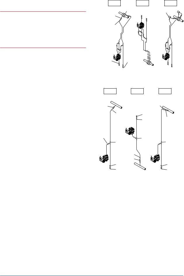
<5. Installing Impulse Piping> |
5-4 |
|
|
 NOTE
NOTE
After completing the connections, close the valves on the process pressure taps (main valves), the valves at the transmitter (stop valves), and the impulse piping drain valves, so that condensate, sediment, dust and other extraneous material cannot enter the impulse piping.
5.2Impulse Piping Connection Examples
Figure 5.5 and 5.6 show examples of typical impulse piping connections. Before connecting the transmitter to the process, study the transmitter installation location, the process piping layout, and the characteristics of the process fluid (corrosiveness, toxicity, flammability, etc.), in order to make appropriate changes and additions to the connection configurations.
Note the following points when referring to these piping examples.
•The high pressure connecting port on the transmitter is shown on the right (as viewed from the front).
•The transmitter impulse piping connection is shown for a vertical impulse piping connection configuration in which the direction of connection is either upwards or downwards.
•If the impulse line is long, bracing or supports should be provided to prevent vibration.
•The impulse piping material used must be compatible with the process pressure, temperature, and other conditions.
•Avariety of process pressure tap valves (main valves) are available according to the type of connection (flanged, screwed, welded), construction (globe, gate, or ball valve), temperature and pressure. Select the type of valve most appropriate for the application.
Liguid |
|
Gas |
Steam |
Tap |
Orifice |
Condensate pot |
|
|
|
|
|
valve |
|
|
|
Union or flange
Tee 
3-valve 
 manifold
Drain |
Drain |
|
|
valve |
plug |
|
|
|
|
|
F0505.ai |
Figure 5.5 |
Impulse Piping Connection Examples |
||
|
for Differential Pressure Transmitters |
||
Liquid |
Gas |
|
Steam |
Tap |
|
Union or flange |
|
|
|
|
|
valve |
|
|
|
Union or flange |
Drain plug |
|
|
|
Tap valve |
||
|
|
Drain valve |
|
Union |
|
|
|
or |
|
|
|
flange |
|
Tee |
|
|
Tee |
Tee |
|
|
|
||
Union or flange |
|
|
|
|
Tap valve |
|
|
|
Drain valve |
|
Drain valve |
|
Drain plug |
|
Drain plug |
|
|
|
F0506.ai |
Figure 5.6 Impulse Piping Connection Examples
for Gauge/absolute Pressure
Transmitters
IM 01C27B01-01EN
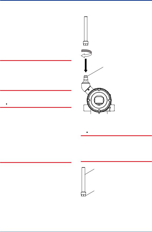
<6. Wiring> |
6-1 |
6.Wiring
6.1MountingAntenna and Wiring
ForAmplifier housing code 8 and 9, an antenna is not attached to the transmitter.The following provides the instructions for mounting the antenna and installing the remote antenna and wiring using antenna extension cable.
 IMPORTANT
The antenna connector is covered with a cap at the time of delivery. Keep the cap attached until the installation of the antenna or antenna cables to protect the inside connection part. The unscrewed cap should be stored in order to replace it immediately after the antenna or antenna cables are removed.
 CAUTION
To maintain the ultimate conditions of radiofrequency signal, protect the connectors of antenna, extension antenna cable, and arrester from the corrosive atmosphere by the following treatment.
1.Clean the connection to be protected.
2.Wind the butyl rubber self-bonding tape around the connection. See the manual of the tape about the winding.
3.To protect the butyl rubber self-bonding tape from the environment such as ultraviolet rays and so on, wind vinyl tape (or a vinyl type self-bonding tape) on it.
6.1.1 Mounting the antenna
Screw the provided antenna into the antenna connector of the transmitter.The antenna may be sold as available accessories and supplied separately.
1.Unscrew the antenna connector cap on the antenna connector.
2.Screw the provided antenna into the antenna connector.Tighten the antenna connector with a torque of 2 to 3 N∙m.
Antenna connector
F0601.ai
Figure 6.1 Mounting the antenna
 CAUTION
When installing the antenna, screw the antenna by tightening the lower nut part. Screwing the antenna by holding the antenna body may cause failure such as cable disconnection.The same manner should be taken when unscrewing the antenna.
Antenna body
Nut part
|
F0602.ai |
Figure 6.2 |
Antenna |
IM 01C27B01-01EN
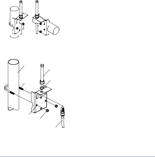
<6. Wiring> |
6-2 |
|
|
6.1.2Mounting ExternalAntenna and WiringAntenna Extension Cable
6.1.2.1Mounting of ExternalAntenna
Mount the external antenna at the proper location according to the wireless environment described in 2.4 Selecting the Installation Location.The mounting to the pipe such as 50 mm (2-inch) pipe needs to secure the enough strength to endure a strong wind, vibration and so on.The antenna must be mounted vertically.
Fixing of ExternalAntenna
Fix an external antenna appropriately using the bracket provided as the external antenna option to 50 mm (2-inch) pipe.
|
|
|
|
|
|
|
|
|
|
|
|
|
|
|
|
|
|
|
|
|
|
|
|
|
|
|
|
|
|
|
|
|
|
|
|
|
|
|
|
|
|
|
|
|
|
|
|
|
|
|
|
|
|
|
|
|
|
|
|
|
|
|
|
|
|
|
|
|
|
|
|
|
|
|
|
|
|
|
|
|
|
|
|
|
|
|
|
|
|
|
|
|
|
|
|
|
|
|
|
|
|
|
|
|
|
|
|
|
|
|
|
|
|
|
|
|
|
|
|
|
|
Vertical pipe |
Horizontal pipe |
||||||||
|
mounting |
mounting |
||||||||
|
|
|
|
|
|
|
|
|
|
|
2-inch pipe
Antenna
Nut
U Bolt
Bracket
Nut
Antenna
Extension Cable
F0603.ai
Figure 6.3 Fixing the remote antenna
Mounting Procedure of External Antenna
1.Fix the bracket by U-bolt and nut to 50 mm (2- inch) pipe.
2.Fix the antenna extension cable to the bracket 1 using the provided nut with a torque of 6 to 7 N∙m as shown in the Figure 6.3 above. Use the nut which is attached to the antenna extension cable.
3.Screw the antenna into the antenna connector of the antenna extension cable on the bracket 1.
Tighten the antenna connector with a torque of 2 to 3 N∙m.
4.Protect the connection as necessary. For details of the protection, see “6.1 Mounting Antenna and Wiring.”
6.1.2.2 Wiring ofAntenna Extension Cable
1.Use the provided antenna extension cable to connect the antenna connector with the external antenna.Tighten the connector of the antenna extension cable with a torque of 2 to 3 N∙m.The minimum bending radius while checking the wiring position should be more than 200 mm.
2.When using two extension cables, the provided arrester should be inserted between these cables.
3.Before the wiring work, confirm the polarities (male/female) of the connectors of antenna, extension antenna cable, and arrester.Tighten the connector of the antenna extension cable with a torque of 2 to 3 N∙m.
4.Protect the connectors of antenna, extension antenna cable, and arrester as necessary. See “6.1 MountingAntenna and Wiring.”
5.Fix the extension antenna cable to the appropriate structure to protect the cable from the vibration, wind, and so on.The minimum bending radius for fixing in the state maintained for a long period should be more than 80 mm.
IM 01C27B01-01EN
Loading...