


 Loading...
User’s
Manual
UV700G
UV Analyzer
(ORGANIC POLLUTANT MONITOR)
IM 12K01B02-01E
IM 12K01B02-01E
6th Edition

<INTRODUCTION> |
i |
INTRODUCTION
This manual describes the operation of the UV700G.
Be sure to read this manual before using the product to ensure proper and safe operation of the instrument. Also safely store the manual so it is readily available whenever necessary.
Product specifications and appearance, as well as the contents of this manual are subject to change without notice.
n Warranty and Responsibility
Yokogawa warrants that the Product shall be free from defects in material and workmanship and agrees to repair or replace free of charge, atYokogawa’s option, any malfunctioned or damaged Product attributable toYokogawa’s responsibility for a period of one (1) year from the delivery unless otherwise agreed with a written agreement. In any one of the following cases, none of the warranties set forth herein shall be extended;
•Any malfunction or damage attributable to improper operation
•Any malfunction attributable to repair or modification by any person not authorized by
Yokogawa
•Any malfunction or damage attributable to the use in an environment not specified in this manual
•Any malfunction or damage attributable to violation of the instructions in this manual or operations in the manner not specified in this manual
•Any malfunction or damage attributable to any cause or causes beyond the reasonable control of Yokogawa such as natural disasters
•Any deterioration in appearance attributable to corrosion, rust, and so on
•Replacement of consumables
YOKOGAWA SHALL NOT BE LIABLE FOR ANY DAMAGES RESULTING FROM ANY MAL-
FUNCTIONS OFTHE PRODUCT,ANYERASURE OF DATA, ORANYOTHER USES OFTHE
PRODUCT.
nNotes on Handling User’s Manuals
•Please hand over the user’s manuals to your end users so that they can keep the user’s manuals on hand for convenient reference.
•Please read the information thoroughly before using the product.
•The purpose of these user’s manuals is not to warrant that the product is well suited to any particular purpose but rather to describe the functional details of the product.
•No part of the user’s manuals may be transferred or reproduced without prior written consent from YOKOGAWA.
•YOKOGAWAreserves the right to make improvements in the user’s manuals and product at any time, without notice or obligation.
•If you have any questions, or you find mistakes or omissions in the user’s manuals, please contact our sales representative or your local distributor.
Media No. IM 12K01B02-01E |
6th Edition : Feb. 2021 (YK) |
IM 12K01B02-01E |
All Rights Reserved Copyright © 2007,Yokogawa Electric Corporation |
|
|

ii |
<INTRODUCTION> |
Safety Precautions
nSafety, Protection, and Modification of the Product
•In order to protect the system controlled by the product and the product itself and ensure safe operation, observe the safety precautions described in this user’s manual. We assume no liability for safety if users fail to observe these instructions when operating the product.
•If this instrument is used in a manner not specified in this user’s manual, the protection provided by this instrument may be impaired.
•If any protection or safety circuit is required for the system controlled by the product or for the product itself, prepare it separately.
•Be sure to use the spare parts approved byYokogawa Electric Corporation (hereafter simply referred to asYOKOGAWA) when replacing parts or consumables.
•Modification of the product is strictly prohibited.
•The following safety symbols are used on the product as well as in this manual.
CAUTION
This symbol gives information essential for understanding the operations and functions.
NOTE
This symbol indicates information that complements the present topic.
n Warning and Disclaimer
The product is provided on an “as is” basis. YOKOGAWA shall have neither liability nor responsibility to any person or entity with respect to any direct or indirect loss or damage arising from using the product or any defect of the product that YOKOGAWA can not predict in advance.
IM 12K01B02-01E

<INTRODUCTION> |
iii |
After-sales Warranty
nDo not modify the product.
nDuring the warranty period, for repair under warranty consult the local sales representative or service office.Yokogawa will replace or repair any damaged parts. Before consulting for repair under warranty, provide us with the model name and serial number and a description of the problem. Any diagrams or data explaining the problem would also be appreciated.
•If we replace the product with a new one, we won’t provide you with a repair report.
•Yokogawa warrants the product for the period stated in the pre-purchase quotation Yokogawa shall conduct defined warranty service based on its standard. When the customer site is located outside of the service area, a fee for dispatching the maintenance engineer will be charged to the customer.
•Returned goods that have been in contact with process fluids must be decontaminated and disinfected prior to shipment. Goods should carry a certificate to this effect, for the health and safety of our employees. Material Safety Data sheets must be included for all components of the process to which the sensor have been exposed.
nIn the following cases, customer will be charged repair fee regardless of warranty period.
•Failure of components which are out of scope of warranty stated in instruction manual.
•Failure caused by usage of software, hardware or auxiliary equipment, whichYokogawa
Electric did not supply.
•Failure due to improper or insufficient maintenance by user.
•Failure due to modification, misuse or outside-of-specifications operation whichYokogawa does not authorize.
•Failure due to power supply (voltage, frequency) being outside specifications or abnormal.
•Failure caused by any usage out of scope of recommended usage.
•Any damage from fire, earthquake, storms and floods, lightning, disturbances, riots, warfare, radiation and other natural changes.
nYokogawa does not warrant conformance with the specific application at the user site. Yokogawa will not bear direct/indirect responsibility for damage due to a specific application.
nYokogawa Electric will not bear responsibility when the user configures the product into systems or resells the product.
nMaintenance service and supplying repair parts will be covered for five years after the production ends. For repair for this product, please contact the nearest sales office described in this instruction manual.
IM 12K01B02-01E

Blank Page

<CONTENTS> |
v |
UV700G UV Analyzer
(ORGANIC POLLUTANT MONITOR)
|
|
|
IM 12K01B02-01E 6th Edition |
|
CONTENTS |
|
|
||
|
INTRODUCTION............................................................................................. |
i |
||
|
Safety Precautions........................................................................................ |
ii |
||
|
After-sales Warranty.................................................................................... |
iii |
||
1. |
Overview.................................................................................................... |
|
1-1 |
|
|
1.1 |
Introduction........................................................................................................ |
1-1 |
|
|
1.2 |
Description of Parts........................................................................................... |
1-2 |
|
|
|
1.2.1 |
Unit...................................................................................................... |
1-2 |
|
|
1.2.2 |
Display................................................................................................ |
1-4 |
2. |
Specification.............................................................................................. |
|
2-1 |
|
|
2.1 |
Standard Specification..................................................................................... |
2-1 |
|
|
2.2 |
Characteristics................................................................................................... |
2-3 |
|
|
2.3 |
Model and Suffix Codes.................................................................................... |
2-4 |
|
|
2.4 |
Overhaul Parts................................................................................................... |
2-4 |
|
|
2.5 |
External Dimensions and Flow Diagrams...................................................... |
2-5 |
|
|
2.6 |
Connection Diagram....................................................................................... |
2-10 |
|
|
2.7 |
Measurement Principle................................................................................... |
2-11 |
|
3. |
Installation................................................................................................. |
|
3-1 |
|
|
3.1 |
Conditions for Installation................................................................................ |
3-1 |
|
|
3.2 |
Installation Method............................................................................................ |
3-2 |
|
|
3.3 |
Piping configuration.......................................................................................... |
3-4 |
|
|
3.4 |
Wiring.................................................................................................................. |
|
3-6 |
|
|
3.4.1 |
Grounding........................................................................................... |
3-6 |
|
|
3.4.2 |
Power Supply..................................................................................... |
3-6 |
|
|
3.4.3 |
Connecting Signal Lines..................................................................... |
3-6 |
|
|
3.4.4 |
Connecting Detector to Converter...................................................... |
3-7 |
|
|
3.4.5 |
Connecting Float Switch Cable of OverflowTank to Converter......... |
3-7 |
4. |
Operation................................................................................................... |
|
4-1 |
|
|
4.1 |
Preparation for Operation................................................................................. |
4-1 |
|
|
4.2 |
Starting Operation............................................................................................. |
4-2 |
|
|
4.3 |
Shutting Down................................................................................................... |
4-3 |
|
|
|
4.3.1 |
For Shut Down within 7 Days............................................................. |
4-3 |
|
|
4.3.2 |
For Shut Down over 7 Days............................................................... |
4-3 |
|
4.4 |
Restarting Operation......................................................................................... |
4-3 |
|
IM 12K01B02-01E

vi |
<CONTENTS> |
|
|
|
|
|
|
|
|
|
|
4.4.1 |
For Shut Down within 7 Days............................................................. |
4-3 |
|
|
4.4.2 |
For Shut Down over 7 Days............................................................... |
4-3 |
5. |
Calibration................................................................................................. |
|
5-1 |
|
|
5.1 |
Calibration Pattern and its Cycle..................................................................... |
5-1 |
|
|
5.2 |
Notes regarding Calibration............................................................................. |
5-2 |
|
|
5.3 |
Calibration Screen Display............................................................................... |
5-2 |
|
|
5.4 |
Calibration of UV/VIS......................................................................................... |
5-3 |
|
|
|
5.4.1 |
How to Prepare Calibration Solution.................................................. |
5-3 |
|
|
5.4.2 |
Common Zero Calibration.................................................................. |
5-6 |
|
|
5.4.3 |
Common Span Calibration................................................................. |
5-9 |
|
|
5.4.4 |
Individual (UV) Span Calibration...................................................... |
5-12 |
|
5.5 |
TURB (turbidity) Span Calibration................................................................. |
5-15 |
|
|
|
5.5.1 |
How to Prepare the Calibration Solution.......................................... |
5-15 |
|
|
5.5.2 |
TURB (turbidity) Span Calibration.................................................... |
5-16 |
6. |
Functions................................................................................................... |
|
6-1 |
|
|
6.1 |
MEAS. (Measurement) Screen......................................................................... |
6-1 |
|
|
6.2 |
Table of Functions............................................................................................. |
6-1 |
|
|
6.3 |
Maintenance Screen Display............................................................................ |
6-2 |
|
|
6.4 |
Maintenance - Setting....................................................................................... |
6-3 |
|
|
|
6.4.1 |
Signal Allocation................................................................................. |
6-3 |
|
|
6.4.2 |
Signal Input Setting............................................................................ |
6-4 |
|
|
6.4.3 |
Output Setting..................................................................................... |
6-5 |
|
|
6.4.4 |
Output Condition Setting.................................................................... |
6-7 |
|
|
6.4.5 |
TimeAdjustment................................................................................. |
6-7 |
|
|
6.4.6 |
LCD Setting........................................................................................ |
6-8 |
|
|
6.4.7 |
Touch PanelAdjustment..................................................................... |
6-9 |
|
|
6.4.8 |
Maker Maintenance Mode.................................................................. |
6-9 |
|
6.5 |
Maintenance - Measurement Setting............................................................. |
6-10 |
|
|
|
6.5.1 |
Measuring Range Setting for each Component............................... |
6-11 |
|
|
6.5.2 |
Setting of Decimal Place for each Component................................ |
6-12 |
|
|
6.5.3 |
Unit Setting for UV, VIS, and UV-αVIS............................................. |
6-12 |
|
|
6.5.4 |
Setting of Turbidity Correction Factor............................................... |
6-13 |
6.5.5Setting of COD Conversion Factor and Turbidity Correction Factor.6-14
|
6.5.6 |
Setting of MAXAlarm Value for COD andTURB (turbidity)............. |
6-15 |
|
6.5.7 |
Setting of MINAlarm Value for COD andTURB (turbidity)................... |
6-16 |
|
6.5.8 |
Unit Setting forTURB (turbidity)....................................................... |
6-17 |
6.6 |
Maintenance - Action....................................................................................... |
6-17 |
|
|
6.6.1 |
Action................................................................................................ |
6-17 |
6.7 |
Maintenance - Check....................................................................................... |
6-18 |
|
|
6.7.1 |
Unit Information................................................................................ |
6-19 |
|
6.7.2 |
Individual ID Setting.......................................................................... |
6-19 |
|
6.7.3 |
External Input/Output Check............................................................ |
6-19 |
IM 12K01B02-01E

|
|
|
<CONTENTS> |
|
vii |
|
|
|
|
|
|
|
|
6.7.4 |
Check Analog Input.......................................................................... |
|
6-20 |
|
|
6.7.5 |
Check Analog Output....................................................................... |
|
6-21 |
|
6.8 |
Data Check....................................................................................................... |
|
6-21 |
|
|
|
6.8.1 |
Log Data Check................................................................................ |
|
6-22 |
|
|
6.8.2 |
Log Data Deletion............................................................................. |
|
6-23 |
|
|
6.8.3 |
Graph Display................................................................................... |
|
6-24 |
|
|
6.8.4 |
Calibration Report Check................................................................. |
|
6-25 |
|
|
6.8.5 |
Calibration Report Deletion.............................................................. |
|
6-26 |
|
|
6.8.6 |
CF Card Transfer.............................................................................. |
|
6-27 |
|
|
6.8.7 |
CF Card Initialization........................................................................ |
|
6-27 |
|
6.9 |
Alarm................................................................................................................. |
|
|
6-28 |
|
|
6.9.1 |
Alarm Check..................................................................................... |
|
6-29 |
|
|
6.9.2 |
Alarm Stop........................................................................................ |
|
6-29 |
|
|
6.9.3 |
Alarm History Check......................................................................... |
|
6-30 |
|
|
6.9.4 |
Alarm History Deletion...................................................................... |
|
6-30 |
7. |
External Input and Output........................................................................ |
|
7-1 |
||
|
7.1 |
Terminal diagram of input and output............................................................. |
|
7-1 |
|
|
7.2 |
Analog Output.................................................................................................... |
|
7-2 |
|
|
7.3 |
Contact Input and Output................................................................................. |
|
7-3 |
|
|
|
7.3.1 |
Contact Output................................................................................... |
|
7-3 |
|
|
7.3.2 |
Contact Input...................................................................................... |
|
7-4 |
|
7.4 |
Saving Data to a CF Card.................................................................................. |
|
7-5 |
|
8 |
Maintenance.............................................................................................. |
|
|
8-1 |
|
|
8.1 |
Maintenance item.............................................................................................. |
|
8-1 |
|
|
8.2 |
Maintenance of Detector................................................................................... |
|
8-2 |
|
|
|
8.2.1 |
Cleaning Method for Measuring Cell.................................................. |
|
8-2 |
|
|
8.2.2 |
Replacement of Wiper Blade Rubber................................................. |
|
8-4 |
|
|
8.2.3 |
Replacement of Desiccant Agent and Seal Washers for Screws |
...... 8-6 |
|
|
|
8.2.4 |
Replacement of Desiccant Agent in the Measuring Cell.................... |
|
8-7 |
|
8.3 |
Cleaning of Sampling Unit.............................................................................. |
|
8-11 |
|
|
|
8.3.1 |
Cleaning of OverflowTank and MeasuringTank.............................. |
|
8-11 |
|
|
8.3.2 |
Removal of Inner Tank of Measuring Tank....................................... |
|
8-12 |
|
8.4 |
Accessories and spare parts......................................................................... |
|
8-13 |
|
9 |
Troubleshooting........................................................................................ |
|
9-1 |
||
|
9.1 |
Table of Status and Operation.......................................................................... |
|
9-1 |
|
|
9.2 |
Table of alarm and Operation........................................................................... |
|
9-1 |
|
|
9.3 |
Alarm Occurrence Condition........................................................................... |
|
9-2 |
|
|
9.4 |
Causes and Measures for Alarm...................................................................... |
|
9-3 |
|
App.1Overview............................................................................................ |
|
App.1-1 |
|||
|
App.1.1 Cautions..................................................................................................... |
|
App.1-1 |
||
|
App.1.2 Composition............................................................................................... |
App.1-1 |
|||
IM 12K01B02-01E

viii |
<CONTENTS> |
|
|
|
|
|
|
|
App.2 Installation........................................................................................ |
|
App.2-1 |
|
App.2.1 Selecting an installation location............................................................ |
|
App.2-1 |
|
App.2.2 Cautions for installation environment.................................................... |
|
App.2-1 |
|
App.2.2.1 Sample water condition.............................................................. |
|
App.2-1 |
|
App.2.2.2 Surrounding environment........................................................... |
|
App.2-1 |
|
App.2.3 Installing UV700G...................................................................................... |
|
App.2-1 |
|
App.2.3.1 Positions of foundation bolts for pole stand................................ |
|
App.2-1 |
|
App.2.3.2 Service and maintenance space................................................ |
|
App.2-2 |
|
App.2.3.3 Figure of completed pole stand mount....................................... |
|
App.2-2 |
|
App.2.3.4 Pole stand assembly.................................................................. |
|
App.2-3 |
|
App.2.3.5 Measuring tank assembly........................................................... |
|
App.2-3 |
|
App.2.3.6 Overflow tank assembly............................................................. |
|
App.2-4 |
|
App.2.3.7 Converter assembly................................................................... |
|
App.2-6 |
|
App.3Piping................................................................................................. |
|
App.3-1 |
|
App.3.1 Piping procedure....................................................................................... |
|
App.3-1 |
|
App.4Wiring................................................................................................. |
|
App.4-1 |
|
App.4.1 Wiring procedure....................................................................................... |
|
App.4-1 |
|
App.4.1.1 Earth connection......................................................................... |
|
App.4-1 |
|
App.4.1.2 Power supply.............................................................................. |
|
App.4-1 |
|
App.4.1.3 Cable connection for detector.................................................... |
|
App.4-2 |
|
App.4.1.4 Float switch cable connection for overflow tank......................... |
App.4-2 |
|
|
App.4.1.5 Signal line connection................................................................. |
|
App.4-2 |
|
Customer Maintenance Parts List...................................... |
CMPL 12K01B02-01E |
|
|
Revision Information................................................................................................ |
|
i |
IM 12K01B02-01E

<1. Overview> |
1-1 |
1.Overview
1.1Introduction
GENERAL
Water pollution control laws and regulations require monitoring of wastewater quality to prevent water pollution in lakes, rivers and enclosed bodies of water. Pollutant load is an index of water quality standards and is defined as the product of the COD (chemical oxygen demand) concentration and the wastewater volume. Certain entities are required to measure pollutant loads and comply with the limits.
Among various methods for COD measurement, automatic ultraviolet absorption spectrometry is the ideal choice on the whole since it provides high correlation between analyzer and laboratory results, measurement continuity and maintainability.
The UV700G Ultraviolet (UV) analyzer is an instrument for continuous on-line measurement using the same cell length modulation method as its predecessor UV400G.
It provides improved operability through a wide measuring range and touch screen interface, high reliability and excellent maintainability.
FEATURES
•Graphic LCD with touch screen on the converter provides easy interactive operation.
•Detector uses the rotary cell length modulation method. Zero check is performed at the time of minimum cell length, virtually eliminating zero drift.
•Continuous cell cleaning with unique wiper system, allowing long term, stable measurement.
•Analyzer covers a wide measuring range: from 0-0.1 Abs to 0-5.0 Abs.
•Flow-through cell type for easy maintenance.
•Data memory function for transferring data to a PC via an optional compact flash (CF) card.
IM 12K01B02-01E
<1. Overview> |
1-2 |
1.2Description of Parts
1.2.1Unit
Hood (optional)
Converter
Float Switch
Overflow Tank
Measuring Tank
Base
Left Side View
Display |
Door |
Detector |
Front View
CAUTION
The stanchions illustrated are typical examples.Appearance and size may vary depending on the specification.
IM 12K01B02-01E
<1. Overview> |
1-3 |
|
|
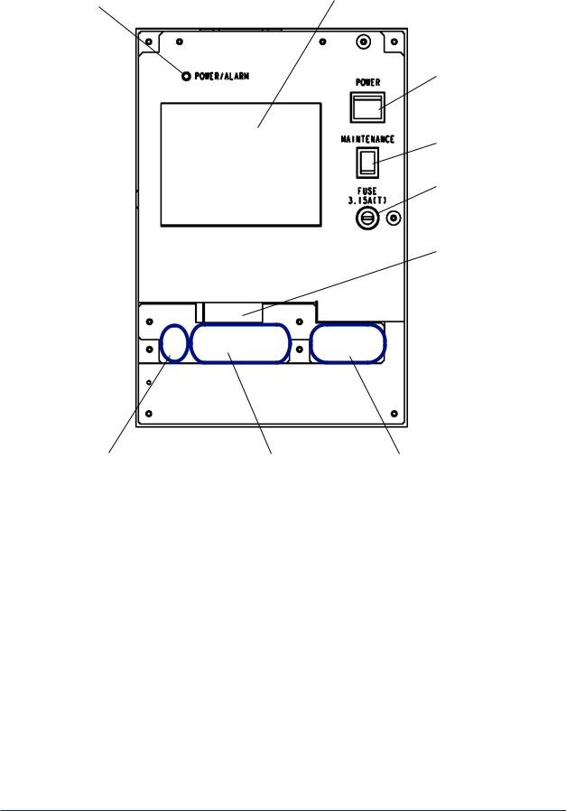
• Inside of the converter
Power / alarm LED |
Display (Touch panel) |
|
Power switch
Maintenance switch
Fuse
CF card insertion slot
. CF CARD
Connectors for the detector |
Signal terminals |
AC power terminals |
IM 12K01B02-01E
<1. Overview> |
1-4 |
1.2.2Display
This section describes the parameters shown on a typical display:
•The display is touch panel. Do not press buttons with wet hands, or a sharp object such as a pen tip or a screwdriver.
•If no buttons are pressed for a certain period of time, the backlight turns OFF.
•If no buttons are pressed for about two hours on displays other than those for measurement, data or alarm, the display turns to the measurement display.
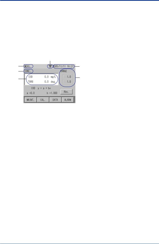
• Example of display-Displaying measurement readings
The display shows measurement readings.
|
7 |
1 |
2 |
3 |
|
4 |
8 |
|
5
 9
9
6
NO. |
Description |
Display example |
1 |
Title of display |
MEAS., SETTING, LOG DATA, etc. |
2 |
Clock |
2004/01/30 09:57 |
3 |
Items to be measured |
Abs, CONC, etc. |
4 |
Readings |
Instantaneous values |
5 |
Conversion factor |
Conversion factors for COD, etc. |
6 |
Operation buttons |
MAINTENANCE, CAL, etc. |
7 |
Status of unit |
WARM UP!: Unit is being warmed up. |
8 |
Range |
Range |
9 |
Switchable measurement items |
Abs, CONC, etc. |
WARM UP!
When the power is turned ON, “WARM UP!” is displayed.This will disappear after one hour.
IM 12K01B02-01E

<1. Overview> |
1-5 |
|
|
• Example of display-Displaying items to be selected
1
2
|
|
|
|
3 |
|
|
|
||
|
|
|
||
NO. |
Description |
Display example |
||
1 |
Title of display |
MAINTENANCE, SETTING, etc. |
||
2 |
Selection keys |
SETTING, MEAS. SETTING, etc. |
||
3 |
Switching keys |
CLOSE etc. |
||
• Example of display - Displaying history and other information
1
2
3
NO. |
Description |
Display example |
1 |
Title of display |
Alarm history, calibration report, etc. |
2 |
Items to be displayed |
Description of alarms, etc. |
3 |
Data list |
– |
IM 12K01B02-01E

Blank Page

<2.Specification> 2-1
2.Specification
2.1Standard Specification
Measurement : |
Organic pollutants in wastewater. |
|
Measurement method: |
|
|
|
Dual optical path, dual wavelength, rotary cell length modulation method |
|
Measurement wavelength: |
|
|
|
Ultraviolet (UV): |
253.7 nm |
|
Visible light (VIS): |
546.1 nm |
Light source: |
Low pressure mercury-vapor lamp |
|
Detector: |
Silicon photo cell, flow-through type |
|
Measuring range (corrected for 10 mm cell) |
|
|
|
UV/VIS absorbance 0-0.1 to 0-5.0 Abs |
|
Display: |
Graphic LCD with touch screen, |
|
|
320 240 dot, with backlight |
|
Indication: |
UV absorbance, VIS absorbance, UVVIS absorbance, COD |
|
|
concentration, turbidity |
|
Resolution: |
0.0001Abs (factory default) or 0.001Abs |
|
COD conversion: |
Conversion equation Y = a bX |
|
|
where Y = COD concentration |
|
|
X = absorbance (UV-VIS) |
|
Turbidity conversion: |
Conversion equation Y = a bX |
|
|
where Y = turbidity, |
|
|
X = absorbance(VIS) |
|
Analog output: |
|
|
Number of outputs: |
3 |
|
Functions: 3 functions selectable: |
|
|
|
UV absorbance / VIS absorbance/ UV-VIS absorbance / COD |
|
|
concentration / turbidity |
|
Specifications: |
4-20 mADC or 0-16 mADC, isolated |
|
|
(non-isolated between channels) |
|
Contact output:
Number of outputs: 6 Functions:
2 functions fixed:
Power off, maintenance status
4 functions selectable:
Total alarm / COD high alarm / turbidity high alarm / light souse malfunction / no sample / cleaning motor error / analyzer error
Descriptions:
Power off:
Activated when power off occurs
Maintenance status:
Activated when instrument is in maintenance or calibration mode or when MAINTENANCE switch is turned on
Total alarm:
Cleaning motor error, light source malfunction and / or analyzer error
IM 12K01B02-01E

|
|
|
<2.Specification> |
2-2 |
|
|
|
||
Specifications: |
Voltage-free contact output, FormA |
|
||
Contact rating: |
0.3A/ 125 VAC, 1A/ 30 V DC (resistive load), independent |
|
||
|
|
common at each output |
|
|
Contact input: |
|
|
|
|
Number of inputs: |
2 |
|
|
|
Functions: |
|
No sample float switch, time adjustment |
|
|
Specifications: |
Voltage-free contact input (open collector can be connected), isolated |
|||
On resistance: |
100 V max. |
|
|
|
Open circuit voltage: |
5.5 V DC |
|
|
|
Short circuit current: |
5 mA max. |
|
|
|
Data memory: |
|
Measured data can be stored in converter and stored data transferred to |
||
|
|
CF card. |
|
|
Log interval: |
|
1 min or 1 hour |
|
|
Log time: |
|
On the hour every hour |
|
|
Retention time: |
Approx. 10 days for 1 min interval |
|
||
|
|
Approx. 1 year for 1 hour interval |
|
|
Calibration method: |
Manual calibration using zero / span standard (calibration solution in |
|
||
|
|
ampoule) (One touch calibration is available) |
|
|
Cleaning method: |
Automatic, continuous wiper cleaning |
|
||
Operating conditions: |
|
|
|
|
Ambient temperature:0 to 40 8C |
|
|
||
Ambient humidity: |
90% RH or less |
|
|
|
Installation location: |
Flat, stable place not subject to severe vibration or shock.Allow pace for |
|||
|
|
maintenance. No dust, mist, corrosive gases are present.Atmospheric |
||
|
|
pressure. Avoid exposure to direct sunlight. Good ventilation. Max. |
|
|
|
|
altitude of 2000 m. |
|
|
Sample conditions: |
|
|
|
|
Temperature: |
|
2 to 40 8C (non-freezing) |
|
|
Pressure: |
20 to 500 kPa |
|
|
|
pH: |
4 to 10 |
|
|
|
Flow rate: |
2 to 20 L/min |
|
|
|
Concentration of suspended solids: |
|
|
||
|
200 mg/L or less |
|
|
|
|
Note: |
Protection against freezing should be provided when needed. |
|
|
Piping connection: |
|
|
|
|
Analyzer with pole-base mount type (UV700G-A-A) |
|
|||
|
|
Sample inlet: |
Rp 1/2 female |
|
|
|
Bypass outlet: |
Rc 1/2 |
|
|
|
Overflow outlet 1: |
13Anominal, elbow fitting |
|
|
|
Overflow outlet 2: |
20Anominal, elbow fitting |
|
|
|
Drain port: |
Rc 1/2 |
|
|
|
Discharge port: |
50Anominal, tube fitting |
|
Analyzer with standard self-supporting type (UV700G-hB-A) |
|
|||
|
|
Sample inlet: |
Rp 1/2 female |
|
|
|
Drain port: |
Rc 1/2 |
|
|
|
Discharge port 1: |
50Anominal, tube fitting |
|
|
|
Discharge port 2: |
VP40 pipe |
|
IM 12K01B02-01E

|
|
<2.Specification> |
2-3 |
|
|
|
|
Wiring: |
|
|
|
Power wiring: |
|
|
|
|
Size: |
1.25 mm2 (AWG16) or larger |
|
|
Connection: |
M4 screw terminal |
|
|
Termination: |
Crimp terminal for M4 screw |
|
Signal wiring: |
|
|
|
|
Size: |
0.08 to 1.5 mm2 (AWG28 to 16) |
|
|
Connection: |
Pin terminal |
|
|
Termination: |
Strip 7 mm of insulation off wire end |
|
Dimensions (excluding projections): |
|
|
|
Converter: |
240(W) 3 104(D) 3 320(H) mm |
|
|
Detector: |
200(W) 3 180(D) 3 403(H) mm |
|
|
Materials (main materials): |
|
|
|
Wetted parts: |
SUS304, R-PVC, fused silica, polypropylene, chloroprene rubber, |
|
|
|
titanium (when option code “/TN” is specified) |
|
|
Stanchion
Material:
Pole-base mount type (UV700G-hA-A):
Iron
Standard self-supporting type (UV700G-hB-A):
Carbon steel plate
Finish: |
|
Converter: |
Epoxy with modified melamine resin, baked, Munsell 5PB8/1 equivalent |
Pole-base mount type (UV700G-hA-A): |
|
|
Epoxy with modified melamine resin, baked, Munsell N1.0 equivalent |
Standard self-supporting type (UV700G-hB-A): |
|
|
Polyurethane resin, baked, Munsell 0.6GY3.1/2.0 equivalent |
Construction: |
Outdoor installation (equivalent to IP54) |
Weight: |
|
Converter: |
Approx. 5.0 kg |
Detector: |
Approx. 5.6 kg |
Pole-base mount type:
|
Approx. 31 kg |
Standard self-supporting type (including converter, detector, overflow tank): |
|
|
Approx. 47 kg |
Power supply: |
100 to 230 VAC 610%, 50/60 Hz |
Grounding: |
JIS Class D grounding (100 V or less, φ1.6 mm copper wire) |
Power consumption: |
100 to 120 VAC, 45 VAmax. |
|
200 to 230 VAC, 60 VAmax. |
2.2Characteristics
Linearity: |
62% FS (65% FS for 2.6 to 5.0Abs) |
Repeatability: |
62% FS (65% FS for 2.6 to 5.0Abs) |
Stability: |
62% FS/24 h (65% FS/24 h for 2.6 to 5.0Abs) |
Response time: |
90% within 1 min (sample flow rate at 5 L/min) |
IM 12K01B02-01E

<2.Specification> 2-4
2.3Model and Suffix Codes
Model |
Suffix |
OptionCode |
Description |
||
|
|
Code |
|
|
|
|
|
|
|
|
|
UV700G |
-- |
- |
------ |
----------- UV analyzer (organic pollutant analyzer) |
|
|
|
|
|
|
|
Language |
-J |
----------- Japanese |
|||
|
-E |
----------- English |
|||
Stanchion |
|
|
N |
----------- |
Without stanchion |
A----------- Pole-base mount type
B----------- Standard self-supporting type2
/ |
|
|
-A ----------- |
Always -A |
|
Option |
|
/H |
Hood for sun protection |
||
|
|
|
|
/TN |
Titanium wetted parts*1 |
*1: |
Should be selected when sample water contains seawater or chlorine. |
||||
See “8.4 Accessories and spare parts” regarding Standard Accessories and Auxiliary parts.
2.4Overhaul Parts
For one year after delivery no parts are required to be replaced except wiper blade rubbers and desiccants.To ensure reliable measurement with simple routine maintenance, it is recommended that the instrument be overhauled every year by Yokogawa. The table below lists parts required for overhaul.
Item |
P/N |
Qty |
Description |
Inspection parts kit |
K9436CA |
1 set |
|
Contents: |
|
|
|
V-ring A |
K9430EP |
2 pcs/set |
Cell |
Seal washer |
K9436CB |
4 pcs/set |
Detector’s upper case |
Seal washer |
K9430ES |
10 pieces |
Cell |
Roller |
K9430EN |
6 pieces |
Cell |
Cell packing 2 |
K9430ER |
4 pcs/set |
Cell |
Desiccant (cell) |
K9430EH |
2 pcs/set |
Cell |
Wiper blade rubber |
K9436CG |
4 pcs/set |
Cell |
Light source |
K9436FY |
1 piece |
Cell |
Desiccant (detector) |
K9430EG |
5 pcs/set |
Cell |
Stepping motor |
K9436GB |
1 piece |
Detector |
Blind cap |
K9436GR |
4 pcs/set |
Detector, case |
Case packing |
K9436GK |
1 piece |
Detector, case |
Note: For yearly overhaul, it is recommended that an inspection parts kit (P/N K9436CA) be purchased.
The kit does not include calibration solutions, which should be purchased separately.
IM 12K01B02-01E

<2.Specification> 2-5
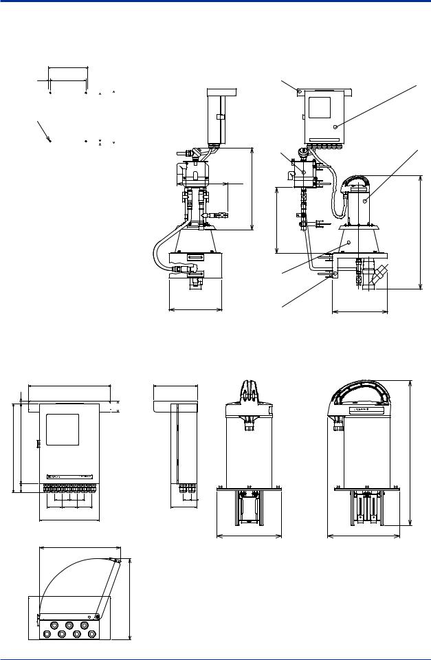
2.5External Dimensions and Flow Diagrams
1. UVAnalyzer with pole-base mount type, UV700G-A-A
n External Dimensions |
Unit: mm |
|
(248 ) |
|
|
|
|
1 |
|
|
|
|
|
|
|
|
*20 |
|
|
|
|
2 |
|
19 |
<![if ! IE]> <![endif]>(390) |
|
|
|
|
|
|
|
|
|
||
|
|
|
|
|
3 |
|
|
|
|
|
|
|
|
|
16 |
4 |
|
|
|
|
|
|
|
|
|
|
|
|
8 |
17 |
|
|
|
|
18 |
|
|
<![if ! IE]> <![endif]>(160) |
|
|
5 |
|
|
|
|
|
||
|
|
|
|
|
|
|
|
9 |
<![if ! IE]> <![endif]>(1506) |
<![if ! IE]> <![endif]>(285) |
|
|
|
|
10 |
|
|
11 |
||
|
|
|
|
|
||
|
|
|
|
|
|
|
| <![if ! IE]> <![endif]>400 |
|
|
|
|
|
12 |
|
|
|
|
|
|
|
|
13 |
|
|
|
|
14 |
|
|
|
|
|
|
|
| <![if ! IE]> <![endif]>350-500 |
|
|
140 |
(209) |
(60) |
7 |
|
15 |
|
|
|
|
|
|
|
|
|
|
|
|
|
|
|
|
|
|
6 |
20 |
260 |
|
10 |
320 |
|
|
|
300 |
|
|
340 |
|
|
|
(345) |
|
|
(520) |
|
|
* Hood for sun protection is optionally available. |
Weight: Approx. 31 kg |
|
1840 |
|
|
|
500 |
340 |
(1000) |
|
|
10 |
320 |
|
|
|
|
|
|
<![if ! IE]> <![endif]>(1000) |
|
|
|
<![if ! IE]> <![endif]>260 |
<![if ! IE]> <![endif]>300 |
<![if ! IE]> <![endif]>2300 |
|
42-ø9 |
<![if ! IE]> <![endif]>20 |
|
|
|
|
|
|
|
|
M8 |
|
<![if ! IE]> <![endif]>1000 |
|
|
|
|
|
|
|
Maintenance Area |
|
|
|
|
Front |
|
|
|
Basic Anchor Bolt Plan
No. |
Item |
Description |
|
1 |
Converter |
|
|
2 |
Wiring port |
|
|
3 |
Pole |
|
|
4 |
Overflow tank |
|
|
5 |
Detector |
|
|
6 |
Drain port (V-4) |
Rc 1/2 |
|
7 |
Discharge port |
50A nominal, tube fitting |
|
8 |
Ball valve (V-1) |
|
|
9 |
Ball valve (V-2) |
|
|
10 |
Bypass outlet |
Rc 1/2 |
|
11 |
Blind plate |
|
|
12 |
Measuring tank |
|
|
13 |
Sample inlet |
Rp 1/2 female |
|
14 |
Detector table |
|
|
15 |
Base |
|
|
16 |
Overflow outlet 2 |
20A nominal, elbow fitting |
|
17 |
Overflow outlet 1 |
13A nominal, elbow fitting |
|
18 |
Ball valve (V-3) |
|
|
19 |
Float switch |
|
|
20 |
Hood for sun protection |
Optional |
|
IM 12K01B02-01E
<2.Specification> 2-6
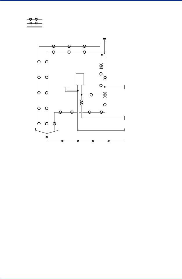
n Flow Diagram
Overflow Tank
Float Switch
Piping Material
ø22/ø15 soft tube VP20 rigid PVC pipe VP13 rigid PVC pipe VP50 rigid PVC pipe
V-3 |
|
Measuring Tank |
V-1 |
|
Vent to Atmosphere |
V-2 |
|
|
|
V-4 |
Overflow Outlet 2
20A nominal, elbow fitting
Overflow Outlet 1
13A nominal, elbow fitting
Sample Inlet
Rp 1/2 female
Bypass Outlet
Rc 1/2
Drain Port
Rc 1/2
Discharge Port
50A nominal, tube fitting
Note: Drain piping should be installed so that back pressure does not develop.
IM 12K01B02-01E

<2.Specification> 2-7
2. UVAnalyzer with standard self-supporting type, UV700G-B-A
n External Dimensions |
Unit: mm |
18* |
|
|
|
|
17 |
|
|
|
4 |
|
|
|
|
|
9 |
|
|
8 |
|
|
|
|
|
|
|
|
|
10 |
<![if ! IE]> <![endif]>1464 |
|
|
|
|
|
| <![if ! IE]> <![endif]>400 |
|
|
|
|
16 |
<![if ! IE]> <![endif]>87 |
|
13 |
|
|
|
|
||
| <![if ! IE]> <![endif]>400 |
|
|
|
|
|
<![if ! IE]> <![endif]>150 |
|
15 |
|
|
|
|
|
|
|
100 |
350 |
(100) |
|
|
|
550 |
|
|
* Hood for sun protection is optionally available.
|
|
|
|
1 |
| <![if ! IE]> <![endif]>320 |
|
|
|
2 |
|
|
|
|
|
|
|
|
|
3 |
| <![if ! IE]> <![endif]>(160) |
|
|
|
5 |
|
|
|
|
|
| <![if ! IE]> <![endif]>(285) |
|
|
|
11 |
|
|
|
12 |
|
|
|
|
|
|
|
|
|
|
14 |
|
(265) |
(240) |
(60) |
<![if ! IE]> <![endif]>(192) |
|
|
|
|
|
20 |
490 |
|
(20) |
|
|
530 |
|
|
7 |
|
|
665 |
|
6 |
|
|
|
|
Weight: Approx. 47 kg
|
2030 |
|
|
|
500 |
530 |
(1000) |
|
|
20 |
490 |
|
|
|
|
|
|
<![if ! IE]> <![endif]>(1000) |
|
|
|
<![if ! IE]> <![endif]>95 |
|
|
|
|
<![if ! IE]> <![endif]>350 |
<![if ! IE]> <![endif]>540 |
<![if ! IE]> <![endif]>2540 |
|
42–ø15 |
<![if ! IE]> <![endif]>95 |
|
|
|
|
<![if ! IE]> <![endif]>1000 |
|
|
|
|
|
|
|
|
Front |
|
|
|
Maintenance Area
No. |
Item |
Description |
1Converter
2Wiring port
3Stanchion
4Overflow tank
5Detector
6 |
Drain port (V-4) |
Rc 1/2 |
7 |
Discharge port 1 |
50A nominal, tube fitting |
8Ball valve (V-1)
9Ball valve (V-2) 10 Ball valve (V-3) 11 Blind plate
12 |
Measuring tank |
|
13 |
Sample inlet |
Rp 1/2 female |
14Detector table
15Base
16 |
Discharge port 2 |
VP40 pipe |
17 |
Float switch |
|
18 |
Hood for sun protection |
Optional |
IM 12K01B02-01E
<2.Specification> 2-8
n Flow Diagram
Piping Material
ø22/ø15 soft tube VP40 rigid PVC pipe VP50 rigid PVC pipe
Float Switch
Overflow Tank
V-3 |
Measuring Tank |
V-1 |
Vent to Atmosphere |
V-2 |
V-4 |
Sample Inlet
Rp 1/2 female
Drain Port Rc 1/2
Discharge Port 1
50A nominal, tube fitting
Discharge Port 2
VP40 pipe
Note: Drain piping should be installed so that back pressure does not develop.
IM 12K01B02-01E
<2.Specification> 2-9
3. UVAnalyzer without stanchion, UV700G-N-A
n External Dimensions
|
240 |
11.5 |
215 |
|
|
|
|
Converter |
|
|
|
|
|
|
|
4-M6 |
|
|
|
<![if ! IE]> <![endif]>295 |
|
<![if ! IE]> <![endif]>320 |
|
|
|||
|
|
Rear |
|
|
|
|
|||||
|
|
|
|
|
|
|
|
|
|||
|
|
|
|
|
|
|
|
|
|
|
|
|
|
|
|
|
|
|
|
|
|
|
|
|
|
|
|
|
<![if ! IE]> <![endif]>12.5 |
|
|
|
|
||
|
|
|
|
|
|
|
|
|
|||
|
Converter Mounting Dimensions |
||||||||||
|
|
|
|
|
|
|
|
|
|||
|
No. |
|
|
|
Item |
|
|
|
|||
|
|
|
|
|
|
|
|
|
|
|
|
|
1 |
|
Converter |
|
|
|
|
|
|
|
|
|
|
|
|
|
|
|
|
|
|
|
|
|
2 |
|
Detector |
|
|
|
|
|
|
|
|
|
|
|
|
|
|
|
|||||
|
3 |
|
Measuring tank |
|
|
|
|||||
|
|
|
|
|
|
|
|||||
|
4 |
|
Detector table |
|
|
|
|||||
|
|
|
|
|
|
|
|
|
|
|
|
|
5 |
|
Overflow tank |
|
|
|
|
|
|
|
|
|
|
|
|
||||||||
|
6 |
|
Hood for sun protection(optional) |
||||||||
|
|
|
|
|
|
|
|
|
|
|
|
Pipes, fittings, and U-bolts are included with shipment.
6 |
1 |
|
(307.5) |
| <![if ! IE]> <![endif]>(500) |
| <![if ! IE]> <![endif]>Head ≥400 |
320
5 |
3 |
4 |
2 |
| <![if ! IE]> <![endif]>(690) |
(333) |
When "UV700G-N-A" is specified, each assembly will be delivered without a stanchion and converter brackets that are provided when "UV700G-A-A" is specified. Hood for sun protection is optionally available.
Converter
Detector
330
|
<![if ! IE]> <![endif]>12.5 |
| <![if ! IE]> <![endif]>354.5 |
<![if ! IE]> <![endif]>320 |
|
<![if ! IE]> <![endif]>(34.5) |
<![endif]> 45
45

UV |
ULTRA VIOLET |
|
ANALYZER |
|
|
60 |
60 |
|
60 |
60 |
60 |
240 |
|
|
Maintenance Area ≥500
<![if ! IE]><![endif]>500≥
<![if ! IE]><![endif]>AreaMaintenance
175
35 |
20 |
104 |
|
|
ULTRA VIOLET ANALYZER |
UV700G |
|
|
<![if ! IE]> <![endif]>403±5 |
180 |
200±3 |
|
Detector Dimensions
Weight: Approx. 5.6 kg
Converter Dimensions Weight: Approx. 5.0 kg
IM 12K01B02-01E
<2.Specification> 2-10
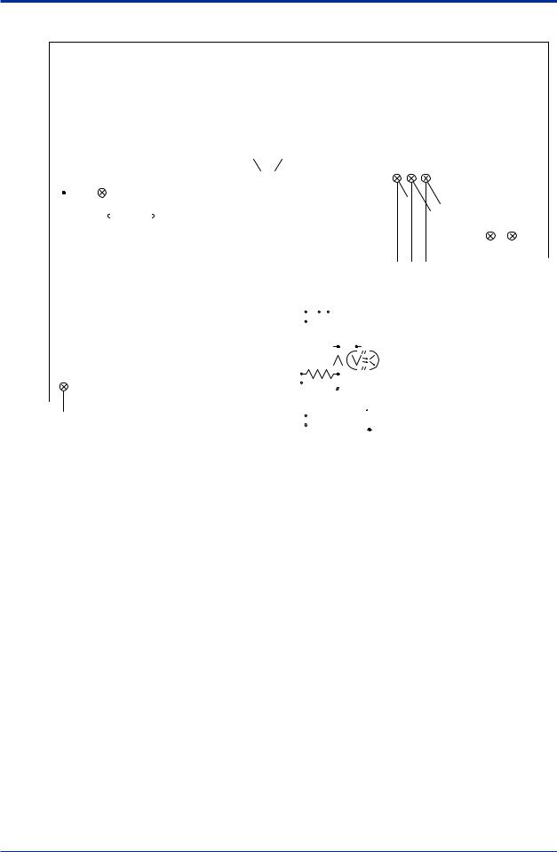
2.6Connection Diagram
Float Switch
|
|
|
|
|
|
|
|
|
|
|
|
|
|
|
|
|
|
|
|
|
|
|
|
|
|
|
|
|
|
|
|
|
|
|
|
|
|
|
|
|
|
|
|
|
|
|
|
|
|
|
|
|
|
|
|
|
|
|
|
|
|
|
|
|
|
|
|
|
|
|
|
|
|
|
|
|
|
|
|
|
|
|
|
|
|
|
|
|
|
|
|
|
|
|
|
|
|
|
|
|
|
|
|
|
|
|
|
|
|
|
|
|
|
|
|
|
|
|
|
|
|
|
|
|
|
|
|
|
|
|
|
|
|
|
|
|
|
|
|
|
|
|
|
|
|
|
|
|
|
|
|
|
|
|
|
|
|
|
|
|
|
|
|
|
|
|
|
|
|
|
|
|
|
|
|
|
|
|
|
|
|
|
|
|
|
|
|
|
|
|
|
|
|
|
|
|
|
|
|
|
|
|
|
|
|
|
|
|
|
|
|
|
|
|
|
|
|
|
|
|
|
|
|
|
|
|
|
|
|
|
|
|
|
|
|
|
|
|
|
|
|
|
|
|
|
|
|
|
|
|
|
|
|
|
|
|
|
|
|
|
|
|
|
|
|
|
|
|
|
|
|
|
|
|
|
|
|
|
|
|
|
|
|
|
|
|
|
|
|
|
|
|
|
|
|
|
|
|
|
|
|
|
|
|
|
|
A-2 |
|
|
|
I-1 |
|
|
|
|
O-1 |
|
|
O-3 |
|
O-5 |
|
|
|
|
|
|
|
|
|
|
|
|||||||||||||||||
|
|
|
|
|
|
|
|
|
|
|
|
|
|
|
|
|
|
|
|
|
|
|
|
|
|
Analog |
|
|
Contact |
|
Contact |
Contact |
Contact Output 5 |
|
|
|
|
|
|
|
|
|
|
|
|||||||||||||||||||||||||
|
|
|
|
|
|
|
|
|
|
|
|
|
|
|
|
|
|
|
|
|
|
|
|
|
|
Output 2 |
|
|
Input 1 |
|
Output 1 |
Output 3 |
(power off) |
|
|
|
|
|
|
|
|
|
|
|
|||||||||||||||||||||||||
|
|
|
|
|
|
|
|
|
|
|
CN1 |
|
|
|
|
|
|
|
Empty |
|
|
|
|
|
|
|
|
|
|
|
|
|
|
|
|
|
|
|
|
|
|
|
|
|
|
|
|
|
|
|
|
Power Supply |
|
|
|
|
|||||||||||||
|
|
|
|
|
|
|
|
2-pin Connector |
|
|
|
|
|
|
|
Terminal 1 |
2 |
|
|
1 |
|
|
2 |
|
1 |
|
2 |
|
|
|
1 |
|
|
2 |
|
|
1 |
|
2 |
|
|
|
L |
E N |
|
|
|
|
|||||||||||||||||||||
|
M3 Shield |
|
|
|
CN2 |
|
|
|
|
|
1 |
2 |
3 |
|
|
4 |
5 |
|
6 |
|
|
7 |
|
8 |
|
9 |
|
10 |
|
|
11 |
|
12 |
|
13 |
|
14 |
|
|
|
|
|
33M4 Ring Terminals |
|
|
|
|
||||||||||||||||||||||
|
4-pin Connector |
|
|
|
|
|
|
|
|
|
|
|
|
|
|
|
|
|
|
|
|
|
|
|
|
|
|
|
|||||||||||||||||||||||||||||||||||||||||
|
Ring Terminal |
|
|
|
|
|
|
|
|
|
|
|
|
|
|
|
|
|
|
|
|
|
|
|
|
|
|
|
|
|
|
|
|
|
|
|
|
|
|
|
|
|
|
|
|
|
|
|
|
|
|
|
|
|
|
|
|
|
|
|
|||||||||
|
|
|
|
|
|
|
|
|
|
|
|
|
|
|
|
|
15 |
|
16 |
|
17 |
|
18 |
19 |
20 |
|
21 |
|
22 |
|
23 |
|
24 |
|
25 |
|
26 |
|
27 |
|
28 |
|
|
|
|
|
|
|
|
|
|
|
|
||||||||||||||||
|
|
|
|
|
|
|
|
|
|
|
|
|
|
|
Internal |
|
|
|
|
|
|
|
|
|
|
|
|
|
|
|
|
1 |
|
|
|
|
|
|
|||||||||||||||||||||||||||||||
|
|
|
|
|
|
|
|
|
|
|
|
|
|
|
|
|
|
|
|
|
|
|
|
|
|
|
|
|
|
|
|
|
|
|
|
|
|||||||||||||||||||||||||||||||||
|
|
|
|
|
|
|
|
|
|
|
|
|
|
|
|
|
|
|
|
|
|
|
|
|
|
|
|
|
|
|
|
|
|
|
|
|
|
|
|
|
|
|
|
|
|
|
|
|
|
|
|
|
|
|
|
|
|
|
|
|
|
|
|
|
|
|
|||
|
|
|
|
|
|
|
|
|
|
|
|
|
|
|
Connections 1 |
2 |
1 |
2 |
1 |
2 |
1 |
2 |
1 |
2 |
1 |
2 |
|
|
|
|
|
|
2 Arrester |
|
|
|
|
|
|
||||||||||||||||||||||||||||||
|
|
|
|
|
|
|
|
|
|
|
|
|
|
|
(Not for Use) |
|
|
|
|
|
|
|
|
|
|
|
|
|
|
|
|
|
|
|
|
|
|
|
|
|
|
|
|
|
|
|
|
|
|
|
|
|
|
|
|
|
|
|
E |
|
|
|
|
|
|
||||
|
|
|
|
|
|
|
|
|
|
|
|
|
|
|
|
|
|
|
|
|
|
|
|
|
|
|
|
|
|
|
|
|
|
|
|
|
|
|
|
|
|
|
|
|
|
|
|
|
|
|
|
|
|
|
|
|
|
|
|
|
|
|
|
||||||
|
|
|
|
|
|
|
|
|
|
|
|
|
|
|
|
|
|
|
|
|
|
Analog |
Analog |
|
Contact |
|
Contact |
|
|
Contact |
Contact Output 6 |
|
|
|
|
|
|
|
|
|
|
|
|||||||||||||||||||||||||||
|
|
|
|
|
|
|
|
|
|
|
|
|
|
|
|
|
|
|
|
|
|
|
|
|
|
|
|
|
|
|
|
|
|
|
|
|
|||||||||||||||||||||||||||||||||
|
|
|
|
|
|
|
|
|
|
|
|
|
|
|
|
|
|
|
|
|
|
Output 1 |
Output 3 |
|
Input 2 |
|
Output 2 |
|
|
Output 4 |
(maintenance status) |
|
|
|
|
|
|
|
|
|
|
||||||||||||||||||||||||||||
|
|
|
|
|
|
|
|
|
|
|
|
|
|
|
|
|
|
|
|
|
|
|
|
A-1 |
|
A-3 |
|
|
|
I-2 |
|
|
|
O-2 |
|
|
|
|
O-4 |
|
|
|
O-6 |
|
|
|
|
|
|
|
|
|
|
|
|||||||||||||||
|
|
|
|
|
|
|
|
|
|
|
|
|
|
|
|
|
|
|
|
|
|
|
|
|
|
|
|
|
|
|
|
|
|
|
|
|
|
|
|
|
|
|
|
|
|
|
|
|
|
|
|
|
|
|
|
|
|
|
|
|
|
|
|
|
|
|
|
|
|
|
|
|
|
|
|
|
|
|
|
|
|
|
|
|
|
|
|
|
|
|
|
|
|
|
|
|
|
|
|
|
|
|
|
|
|
|
|
|
|
|
|
|
|
|
|
|
|
|
|
|
|
|
|
|
|
|
|
|
|
|
|
|
Converter |
|
Converter |
|
|||
|
|
|
|
|
|
|
|
|
|
|
|
|
|
|
|
|
|
|
|
|
|
|
|
|
|
|
|
|
|
|
|
|
|
|
|
|
|
|
|
|
|
|
|
|
|
|
|
|
|
|
|
|
|
|
|
|
|
|
|
|
|
|
(Chassis) |
(Door) |
|||||
|
|
|
|
|
|
|
|
|
|
|
|
|
|
|
|
|
|
|
|
|
|
|
|
|
|
|
|
|
|
|
|
|
|
|
|
|
|
|
|
|
|
|
|
|
|
|
|
|
|
|
|
|
|
|
|
|
|
|
100-230 V AC 610%, |
|
|
|
|||||||
|
Dedicated Cables |
|
|
|
|
|
|
|
|
|
|
|
|
|
|
|
|
|
|
|
|
|
|
|
|
|
|
|
|
|
|
|
|
|
|
|
|
|
|
|
|
|
|
|
|
|
|
|
|
|
|
|
|
50/60 Hz, 60 VA max. |
|
|
|
||||||||||||
|
|
|
|
|
|
|
|
|
|
|
|
|
|
|
|
|
|
|
|
|
|
|
|
|
|
|
|
|
|
|
|
|
|
|
|
|
|
|
|
|
|
|
|
|
|
|
|
|
|
|
|
|
|
|
|
|
|
|
|
|
|
|
|
|
|
|
|
||
|
|
|
|
|
|
|
|
|
|
|
|
|
|
|
|
|
|
|
|
|
|
|
|
|
|
|
Signal Type |
|
|
|
|
|
|
|
|
|
|
I/O Circuit |
|
|
|
Specification |
|
|
|
||||||||||||||||||||||||
|
|
|
|
|
|
|
|
|
|
|
|
|
|
|
|
|
|
|
|
|
|
Contact signal output |
|
|
|
|
|
|
|
|
|
|
|
|
|
|
|
|
|
|
|
|
|
|
Contact rating: |
|
|
|
|||||||||||||||||||||
|
|
|
|
|
|
|
|
|
|
|
|
|
|
|
|
|
|
|
|
|
|
|
|
|
|
|
|
|
|
|
|
|
|
|
|
|
|
|
|
|
|
|
|
|
|
|
|||||||||||||||||||||||
|
|
|
|
|
|
|
|
|
|
|
|
|
|
|
|
|
|
|
|
|
|
|
|
|
|
|
|
|
|
|
|
|
|
|
|
|
|
|
|
|
|
|
|
0.3 A/125 V AC, 1A/30 V DC (resistive load) |
|||||||||||||||||||||||||
|
|
|
|
|
|
|
|
|
|
|
|
|
|
|
|
|
|
|
|
|
|
|
|
|
|
|
|
|
|
|
|
|
|
|
|
|
|
|
|
|
|
|
|
|
|
|
|
|
|
|
|
|
|
|
|
|
|
|
Voltage free contact signal output |
|
|
|
|||||||
|
|
|
|
|
|
|
|
|
|
|
|
|
|
|
|
|
|
|
|
|
|
|
|
|
|
|
|
|
|
|
|
|
|
|
|
|
|
|
|
|
|
|
|
|
|
|
|
|
|
|
|
|
|
|
|
|
|
|
|
|
|
|
|
|
|
|
|
|
|
|
|
|
|
|
|
|
|
|
|
|
|
|
|
|
|
|
|
|
|
|
|
|
|
|
|
|
|
|
|
|
|
|
|
|
|
|
|
|
|
|
|
|
|
|
|
|
|
|
|
|
|
15V |
|
|
|
|
Voltage free contact signal input |
|
|
|
|||||||||
|
|
|
|
|
|
|
Detector |
|
|
|
|
|
|
|
|
|
|
|
|
|
|
|
|
|
|
|
|
|
|
|
|
|
|
|
|
|
|
|
|
|
|
|
|
|
|
|
|
|
|
|
|
Isolated input (shared negative) |
|
|
|
||||||||||||||
|
|
|
|
|
|
|
|
|
|
|
|
|
|
|
|
|
|
|
|
|
|
|
|
|
|
|
|
|
|
|
|
|
|
|
|
|
|
|
|
|
|
|
|
|
|
|
|
|
|
|
|||||||||||||||||||
M5 |
|
|
|
|
|
|
|
|
|
|
|
|
|
|
|
|
|
|
|
|
|
|
Contact signal input |
|
|
|
|
|
|
|
470V |
|
|
|
|
|
|
|
|
|
|
On resistance: 100 V max. |
|
|
|
||||||||||||||||||||||||
Ground Bolt |
|
|
|
|
|
|
|
|
|
|
|
|
|
|
|
|
|
|
|
|
|
|
|
|
|
|
|
|
|
|
|
|
|
|
|
1 |
|
|
|
|
|
|
|
|
|
|
|
|
|
|
|
|
|
|
|
Open circuit voltage: 5.5 V DC |
|
|
|
||||||||||
|
|
|
|
|
|
|
|
|
|
|
|
|
|
|
|
|
|
|
|
|
|
|
|
|
|
|
|
|
|
|
|
|
|
|
|
|
|
|
|
|
|
|
|
|
|
|
|
|
|
|
|
|
|
|
Photocoupler |
Short circuit current: 5 mA max. |
|
|
|
||||||||||
|
|
|
|
|
|
|
|
|
|
|
|
|
|
|
|
|
|
|
|
|
|
|
|
|
|
|
|
|
|
|
|
|
|
|
|
|
2 |
|
|
|
|
|
|
|
|
|
|
|
|
|
|
|
|
|
|
|
|
|
|
||||||||||
|
|
|
|
|
|
|
|
|
|
|
|
|
|
|
|
|
|
|
|
|
|
|
|
|
|
|
|
|
|
|
|
|
|
|
|
|
|
|
|
|
|
|
|
|
|
|
|
|
|
|
|
|
|
|
|
|
|
|
|
|
|
|
|
|
|
|
|
|
|
|
|
|
|
|
|
|
|
|
|
|
|
|
|
|
|
|
|
|
|
|
|
|
|
|
|
|
|
|
|
|
|
|
|
|
|
|
|
|
|
|
|
|
|
|
|
|
|
|
|
|
|
|
|
|
|
|
|
|
0-16/4-20 mA DC |
|
|
|
|||||||
|
Stanchion |
|
|
|
|
|
|
|
|
|
|
|
|
|
|
|
|
|
|
|
Analog signal output |
|
|
|
|
|
|
|
|
|
|
|
|
|
|
|
|
|
|
|
|
|
|
|
|
|
|||||||||||||||||||||||
Class D Grounding |
|
|
|
|
|
|
|
|
|
|
|
|
|
|
|
|
|
|
|
|
|
|
1 |
|
|
|
|
|
|
|
|
|
|
|
|
|
|
|
|
|
|
Current signal output |
|
|
|
||||||||||||||||||||||||
|
|
|
|
|
|
|
|
|
|
|
|
|
|
|
|
|
|
|
|
|
|
|
|
|
|
|
|
|
|
|
|
|
|
|
|
|
|
|
|
|
|
||||||||||||||||||||||||||||
|
|
|
|
|
|
|
|
|
|
|
|
|
|
|
|
|
|
|
|
|
|
|
|
|
|
|
|
|
|
|
|
|
|
|
|
|
|
|
|
2 |
|
|
|
|
|
|
|
|
|
|
|
|
|
|
|
|
|
|
Isolated input (shared common) |
|
|
|
|||||||
|
|
|
|
|
|
|
|
|
|
|
|
|
|
|
|
|
|
|
|
|
|
|
|
|
|
|
|
|
|
|
|
|
|
|
|
|
|
|
|
|
|
|
|
|
|
|
|
|
|
|
|
|
|
|
|
COM |
Load resistance 600 V max. |
|
|
|
|||||||||
|
|
|
|
|
|
|
|
|
|
|
|
|
|
|
|
|
|
|
|
|
|
|
|
|
|
|
|
|
|
|
|
|
|
|
|
|
|
|
|
|
|
|
|
|
|
|
|
|
|
|
|
|
|
|
|
|
|
|
|
|
|
|
|
|
|
|
|
|
|
IM 12K01B02-01E
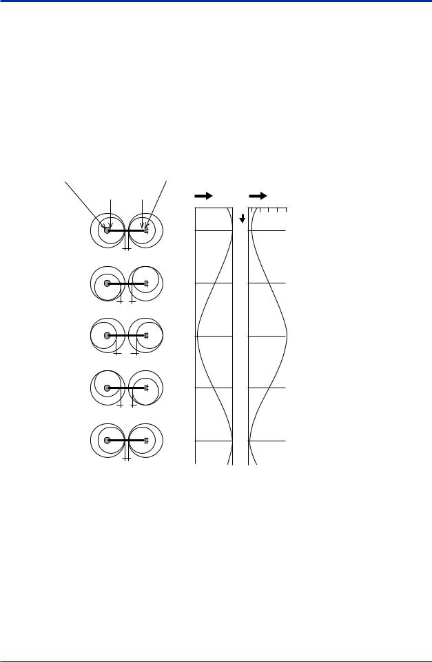
<2.Specification> 2-11
2.7Measurement Principle
The rotary cell length modulation method, which combines high performance and reliability, is adopted in this unit.
Two cylinder cells are placed, arranged with the light source and detector in a position where they are decentered from the center of cylinder as shown in the figure below. By rotating these two cylinder cells with the centers of the light source and detector as the rotation center, the distance between the 2 cylinders (cell length) is modulated continuously and periodically.The signal input to the detector from the light source is the signal which changes the difference in light intensity between the maximum cell length (θ = 180 degrees) and the minimum cell length (θ = 0 degree) into the amplitude. Wide range measurement becomes possible by selecting the optimum cell length and calculating according to the change of cell length.
Rotation center of decentered cell Center of light source
Center of cylinder cell
θ=0°
L1
θ=90°
L2
θ=180°
L3
θ=270°
L2
θ=360°
L1
Rotation center of decentered cell Center of detector
Output signal Cell length
θ L1 L3
0°
90°
180°
270°
360°
• Optical compensation
Optical compensation is attained by the rotary cell length modulation method. Information required for optical compensation is the change of light intensity due to the light source, detector, contamination of the measuring cell etc. This change in light intensity information can be obtained by monitoring the light intensity when at the minimum cell length (θ = 0 degree).
• Turbidity compensation (TURB)
This unit can measure ultraviolet (UV) and visible light (VIS) absorbances independently. UVαVIS display is possible by setting the turbidity correction factor (α), thus a more reliable turbidity compensation can be performed.
IM 12K01B02-01E

<2.Specification> 2-12
• TURB (turbidity) Measurement
TURB measurement is performed by using the visible light (VIS) absorbance.
The measurement method is the transmitting absorption method.
Calibration with the standard solution enables a simple measurement of TURB.
Measure in the measurement range of 200 deg. or below. If measuring in a measurement range that exceeds the specified value, the linearity deteriorates due to the scattering light influence.
• How to Calculate the COD Conversion Factor
If it is judged that there is obviously a linear function between the measurement concentration Xi (i = 1, 2, ...n) and corresponding manual analysis valueYi (i = 1, 2, ...n), the calibration curve formula (regression formula) is expressed as follows:
Y = a + bX
The gradient of this regression line X-axis (b) and theY-axis segment (b) can be calculated by using the measurement value and the least-square method as in the following formula.
|
|
|
|
|
|
|
|
|
|
|
|
a=Y |
- bX |
|
|
|
|||||||
|
|
|
|
|
|
|
nSXiYi - (SXi)(SYi) |
||||
b= |
(Xi - X)(Yi - Y) |
= |
|||||||||
|
|
|
|
|
|
|
|
|
2 - (SXi )2 |
||
|
S(Xi - X)2 |
nSXi |
|||||||||
|
|
|
|||||||||
“a” and “b” are rounded to a value which is larger by 1 digit according to the number of significant figures of the measurement value.
IM 12K01B02-01E

<3. Installation> |
3-1 |
3.Installation
3.1Conditions for Installation
•The unit is weather-proofed for outdoor installation; however, do not install the unit in places subject to direct sunlight.
•Install the unit near the water sampling point.
•Install the unit where a water-supply system, drainage facilities and a power supply are provided.
•Install the unit in a place that is well ventilated, free from dirt or dust, and where no corrosive gases will be generated.
•Install the unit in a place that is free from strong vibration or ferromagnetic fields.
•Install the unit where enough space is provided for conducting routine inspections and maintenance.
•Secure the unit using anchor bolts.
•Install the unit where enough space is provided for conducting services.
IM 12K01B02-01E
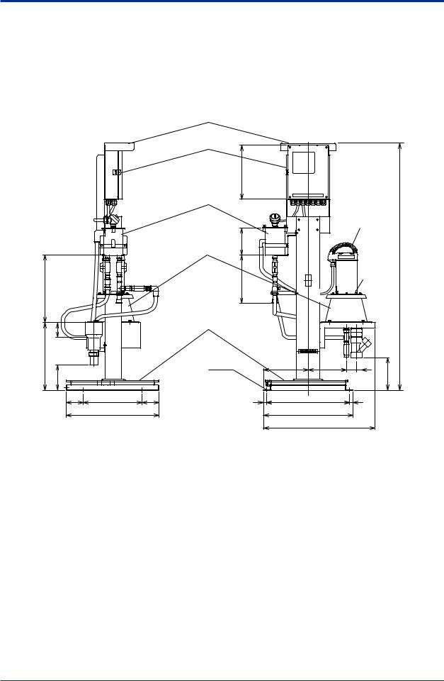
<3. Installation> |
3-2 |
3.2Installation Method
1.UVAnalyzer with standard self-supporting type, UV700G-B-A
•Secure the base with the reference bolts.
•Refer to 3.3 and 3.4 for piping and wring.
Unit: mm
| <![if ! IE]> <![endif]>400 |
|
|
| <![if ! IE]> <![endif]>87 |
|
|
| <![if ! IE]> <![endif]>400 |
|
|
| <![if ! IE]> <![endif]>150 |
|
|
100 |
350 |
(100) |
|
550 |
|
Hood (optional) |
|
|
|
|
|
Converter |
|
|
|
|
|
|
<![if ! IE]> <![endif]>320 |
|
|
|
|
Overflow tank |
|
|
|
|
|
|
|
|
|
Detector |
|
Measuring tank |
<![if ! IE]> <![endif]>(160) |
|
|
|
|
|
|
|
|
|
|
|
<![if ! IE]> <![endif]>(285) |
|
|
|
<![if ! IE]> <![endif]>1464 |
|
|
|
|
Wing nuts |
|
|
|
|
|
(4 points) |
|
|
|
|
|
|
|
Base |
|
|
|
|
|
4 - ø15 |
(265) |
(240) |
(60) |
<![if ! IE]> <![endif]>(192) |
|
|
|
|
|
|
|
|
20 |
490 |
|
(20) |
|
|
|
530 |
|
|
|
|
|
|
665 |
|
|
IM 12K01B02-01E

<3. Installation> |
3-3 |
2.UVAnalyzer with Pole-base mount type, UV700G-A-A
•Assemble the base, measuring tank, overflow tank and converter as guided in theAppendix.
•Secure the base with the reference bolts.
Unit: mm
Hood (optional)
Converter
Overflow tank
Detector
Measuring tank
Wing nuts
 (4 points)
Base
Secure with M8 bolts (4 points)
IM 12K01B02-01E
Loading...