


 Loading...
User’s |
Model DY |
|
|
|
|
|
|
|
|||||||
|
|
|
|
|
|
|
|||||||||
|
|
|
|
|
|
|
|||||||||
Manual |
Vortex Flowmeter |
||||||||||||||
|
(Integral Type, Remote Type) |
||||||||||||||
|
Model DYA |
||||||||||||||
|
Vortex Flow Converter |
||||||||||||||
|
(Remote Type) |
||||||||||||||
|
|
|
|
|
|
|
|
|
|
|
|
|
|
|
|
|
|
|
|
|
|
|
|
|
|
|
|
|
|
|
|
|
|
|
|
|
|
|
|
|
|
|
|
|
|
|
|
|
|
|
|
|
|
|
|
|
|
|
|
|
|
|
|
|
|
|
|
|
|
|
|
|
|
|
|
|
|
|
|
IM 01F06A00-01EN
16th Edition

i
Model DY Vortex Flowmeter
(Integral Type, Remote Type)
Model DYA Vortex Flow Converter
(Remote Type)
IM 01F06A00-01EN 16th Edition
Contents
1. |
INTRODUCTION........................................................................................ |
1-1 |
|
|
1.1 |
Using This Instrument Safety.......................................................................... |
1-2 |
|
1.2 |
Warranty............................................................................................................. |
1-3 |
|
1.3 |
ATEX Documentation ....................................................................................... |
1-4 |
2. |
HANDLING PRECAUTIONS..................................................................... |
2-1 |
||
|
2.1 |
Checking Model and Specifications ............................................................... |
2-1 |
|
|
2.2 |
Transportation and Storage Precautions....................................................... |
2-1 |
|
3. |
INSTALLATION |
......................................................................................... |
3-1 |
|
|
3.1 |
Installation Precautions ................................................................................... |
3-1 |
|
|
3.2 |
Piping Precautions ........................................................................................... |
3-1 |
|
|
3.3 |
Maintenance ......................................................................................of Piping |
3-5 |
|
|
3.4 |
Cryogenic ...................and High Process Temperature Version Insulation |
3-6 |
|
|
3.5 |
Mounting .......................................................................................Procedures |
3-6 |
|
4. |
WIRING ...................................................................................................... |
|
4-1 |
|
|
4.1 |
Load Resistance ............................................................of Output Condition |
4-1 |
|
|
4.2 |
Selection .............................................................................................of Wires |
4-2 |
|
|
4.3 |
Connection ........................................................................................................ |
4-2 |
|
|
4.4 |
Connection ....................................................................of DYC Signal Cable |
4-5 |
|
|
4.5 |
End Processing ...............................................Method of DYC Signal Cable |
4-6 |
|
|
|
4.5.1 ............................................................. |
For Vortex Flowmeter (DY - N) |
4-6 |
|
|
4.5.2 ...................................................... |
For Vortex Flow Converter (DYA) |
4-7 |
|
4.6 |
Wiring Procedures ...............................................................and Precautions |
4-8 |
|
|
4.7 |
Grounding.......................................................................................................... |
4-9 |
|
5. |
BASIC OPERATING .......................................................PROCEDURES |
5-1 |
||
|
5.1 |
Display Con ......................................................................................figuration |
5-1 |
|
|
5.2 |
Display Contents............................................................................................... |
5-2 |
|
|
5.3 |
Display Mode..................................................................................................... |
5-3 |
|
|
|
5.3.1 ...................... |
Changes to Engineering Display Unit from % Display |
5-4 |
|
|
5.3.2 ............................ |
Indicate the Total Rate in the Data Display(Lower) |
5-5 |
|
5.4 |
Setting Mode...................................................................................................... |
5-6 |
|
|
|
5.4.1 .............................................. |
Display Con fi guration of Setting Mode |
5-6 |
|
|
5.4.2 .......................................................................... |
Data Setting Method |
5-7 |
16th Edition : Oct. 2013(KP) |
IM 01F06A00-01EN |
All Rights Reserved, Copyright © 2001. Yokogawa Electric Corporation |
|

ii
6. |
PARAMETERS .......................................................................................... |
6-1 |
|
|
6.1 |
digitalYEWFLO Parameters............................................................................. |
6-1 |
|
6.2 |
Multi-Variable Type (/MV) Parameters............................................................. |
6-1 |
|
6.3 |
Parameters List ................................................................................................. |
6-1 |
|
6.4 |
Parameters Description ................................................................................. |
6-11 |
|
6.5 |
Self-Diagnostic (Error Code List).................................................................. |
6-20 |
7. |
OPERATION FOR THE BRAIN TERMINAL (BT200) .............................. |
7-1 |
|
|
7.1 |
Connection Method for the BT200 .................................................................. |
7-1 |
|
7.2 |
BT200 Screen and Displaying Flow Rate ....................................................... |
7-2 |
|
7.3 |
Setting Parameters using BT200 .................................................................... |
7-3 |
8. |
OPERATION VIA HART CONFIGURATION TOOL (HART 5)................. |
8-1 |
|
|
8.1 |
HART Protocol Revision .................................................................................. |
8-1 |
|
8.2 |
HART Configuration Tool and Matching of Device Revision....................... |
8-1 |
|
8.3 |
Setting Parameters using DTM ....................................................................... |
8-2 |
8.4Interconnection between digitalYEWFLO and
|
|
HART Configuration Tool................................................................................. |
8-2 |
|
|
8.5 |
Basic Setup........................................................................................................ |
8-2 |
|
|
8.6 |
Parameter Setting ............................................................................................. |
8-3 |
|
|
8.7 |
Data Renewing and Upload/Download function ........................................... |
8-3 |
|
|
8.8 |
Self-Diagnostic.................................................................................................. |
8-3 |
|
|
8.9 |
Software Write Protect ..................................................................................... |
8-3 |
|
|
8.10 |
Specific Functions of HART Configuration Tool........................................... |
8-3 |
|
|
|
8.10.1 |
Burst Mode......................................................................................... |
8-3 |
|
|
8.10.2 |
Multidrop Mode .................................................................................. |
8-4 |
|
|
8.10.3 Switching HART Protocol Revision ................................................... |
8-4 |
|
|
|
8.10.4 Other Operations for the HART Configuration Tool........................... |
8-5 |
|
|
8.11 |
Menu Tree (HART 5).......................................................................................... |
8-6 |
|
9. |
OPERATION VIA HART CONFIGURATION TOOL (HART 7)................. |
9-1 |
||
|
9.1 |
HART Protocol Revision .................................................................................. |
9-1 |
|
|
9.2 |
HART Configuration Tool and Matching of Device Revision....................... |
9-1 |
|
|
9.3 |
Setting Parameters using DTM ....................................................................... |
9-1 |
|
9.4Interconnection between digitalYEWFLO and
|
HART Configuration Tool................................................................................. |
9-2 |
|
9.5 |
Basic Setup........................................................................................................ |
9-2 |
|
9.6 |
Parameter Setting ............................................................................................. |
9-3 |
|
9.7 |
Data Renewing and Upload/Download function ........................................... |
9-3 |
|
9.8 |
Self-Diagnostic.................................................................................................. |
9-3 |
|
9.9 |
Software Write Protect ..................................................................................... |
9-3 |
|
9.10 |
Specific Functions of HART Configuration Tool........................................... |
9-3 |
|
|
9.10.1 |
Process Variable Setup (Dynamic Variables).................................... |
9-3 |
|
9.10.2 |
Burst Mode......................................................................................... |
9-4 |
|
9.10.3 |
Event Notification............................................................................... |
9-7 |
IM 01F06A00-01EN

iii
|
|
9.10.4 |
Multidrop Mode .................................................................................. |
9-8 |
|
|
9.10.5 Loop Test, Simulation, and Squawk................................................... |
9-9 |
|
|
|
9.10.6 Switching HART Protocol Revision ................................................. |
9-12 |
|
|
|
9.10.7 Other Operations for the HART Configuration Tool......................... |
9-13 |
|
|
9.11 |
Menu Tree (HART 7)........................................................................................ |
9-14 |
|
10. |
OPERATION ............................................................................................ |
|
10-1 |
|
|
10.1 |
Adjustment ...................................................................................................... |
10-1 |
|
|
|
10.1.1 |
Zero Adjustment............................................................................... |
10-1 |
|
|
10.1.2 |
Span Adjustment.............................................................................. |
10-1 |
|
|
10.1.3 |
Loop Test.......................................................................................... |
10-1 |
|
|
10.1.4 Totalizer Start and Totalizer Reset ................................................... |
10-2 |
|
|
|
10.1.5 Setting of Pulse Output (Scaling)..................................................... |
10-2 |
|
|
|
10.1.6 Setting of Burnout Switch................................................................. |
10-2 |
|
|
|
10.1.7 Setting of Write Protect Switch ........................................................ |
10-3 |
|
|
|
10.1.8 |
Power Failure................................................................................... |
10-3 |
|
10.2 |
Adjustment for Manual Mode ........................................................................ |
10-3 |
|
|
|
10.2.1 |
Low Cut Adjustment......................................................................... |
10-3 |
|
|
10.2.2 |
Zero Tuning...................................................................................... |
10-3 |
11. |
MAINTENANCE....................................................................................... |
|
11-1 |
|
|
11.1 |
Changing the Converter and the Terminal Box Orientation....................... |
11-2 |
|
|
11.2 |
Indicator Removal and Rotation.................................................................... |
11-3 |
|
|
11.3 |
Amplifier Unit Removal .................................................................................. |
11-3 |
|
|
11.4 |
Amplifier Unit Assembling............................................................................. |
11-3 |
|
|
11.5 |
Vortex Shedder Removal ............................................................................... |
11-4 |
|
|
11.6 |
Flow Calculation ............................................................................................. |
11-6 |
|
12. |
TROUBLESHOOTING ............................................................................ |
12-1 |
||
|
12.1 |
Large Errors or Unstable Output................................................................... |
12-1 |
|
|
12.2 |
The Indication Goes to Zero at Certain Time ............................................... |
12-1 |
|
|
12.3 |
No Output When The Fluid is Flowing.......................................................... |
12-2 |
|
|
12.4 |
Output is Indicated at Zero Flow ................................................................... |
12-3 |
|
|
12.5 |
Multi-Variable Type (/MV)................................................................................ |
12-4 |
|
13. |
GENERAL SPECIFICATIONS ................................................................ |
13-1 |
||
|
13.1 |
Standard Specifications................................................................................. |
13-1 |
|
|
13.2 |
Model And Suffix Codes................................................................................. |
13-5 |
|
|
13.3 |
Option Specifications..................................................................................... |
13-8 |
|
13.3.1Option Multi-Variable (Built-In Temperature Sensor)
|
|
Type (/MV) ..................................................................................... |
13-10 |
|
13.3.2 |
Option Reduced Bore Type (/R1, /R2) ........................................... |
13-11 |
13.4 |
Sizing |
.............................................................................................................. |
13-11 |
13.5 |
Detailed .........................................................................................Accuracy |
13-13 |
|
13.6 |
Option ............................Specifications (For Explosion Protected Type) |
13-20 |
|
13.7 |
External ....................................................................................Dimensions |
13-22 |
|
IM 01F06A00-01EN

iv
14. |
EXPLOSION PROTECTED TYPE INSTRUMENT................................. |
14-1 |
|
|
14.1 |
ATEX................................................................................................................. |
14-1 |
|
14.2 |
FM ..................................................................................................................... |
14-4 |
|
14.3 |
IECEx................................................................................................................ |
14-7 |
|
14.4 |
CSA................................................................................................................... |
14-9 |
|
14.5 |
SAA................................................................................................................. |
14-12 |
|
14.6 |
TIIS.................................................................................................................. |
14-14 |
15. |
PED (PRESSURE EQUIPMENT DIRECTIVE) ....................................... |
15-1 |
|
INSTALLATION AND OPERATING PRECAUTIONS FOR TIIS FLAMEPROOF EQUIPMENT
Revision Information
IM 01F06A00-01EN

<1. INTRODUCTION> |
1-1 |
1.INTRODUCTION
Thank you for purchasing the digitalYEWFLO vortex flowmeter.
To ensure correct use of the instrument, please read this manual thoroughly and fully understand how to operate the instrument before operating it.
■Regarding This Manual
•This manual should be provided to the end user.
•The contents of this manual may be changed without prior notice.
•All rights are reserved. No part of this manual may be reproduced in any form without Yokogawa’s written permission.
•Yokogawa makes no warranty of any kind with regard to this material, including, but not limited to, implied warranties of merchantability and suitability for a particular purpose.
•All reasonable effort has been made to ensure the accuracy of the contents of this manual. However, if any errors or omissions are found, please inform Yokogawa.
•The specifications covered by this manual are limited to those for the standard type under the specified model number break-down and do not cover custom-made instruments.
•Please note that this manual may not be revised for any specification changes, construction changes or operating part changes that are not considered to affect function or performance.
•Yokogawa assumes no responsibilities for this product except as stated in the warranty.
•If the customer or any third party is harmed by the use of this product, Yokogawa assumes no responsibility for any such harm owing to any defects in the product which were not predictable, or for any indirect damages.
■Safety and Modification Precautions
•The following general safety precautions must be observed during all phases of operation, service, and repair of this instrument. Failure to comply with these precautions or with specific WARNINGS given elsewhere in
this manual violates safety standards of design, manufacture, and intended use of the instrument. Yokogawa assumes no liability for the customer’s failure to comply with these requirements. If this instrument is used in
a manner not specified in this manual, the protection provided by this instrument may be impaired.
•Yokogawa will not be liable for malfunctions or damage resulting from any modification made to this instrument by the customer.
•The following safety symbol marks are used in this manual and instrument.
 WARNING
A WARNING sign denotes a hazard. It calls attention to procedure, practice, condition or the like, which, if not correctly performed or adhered to, could result in injury or death of personnel.
 CAUTION
A CAUTION sign denotes a hazard. It calls attention to procedure, practice, condition or the like, which, if not correctly performed or adhered to, could result in damage to or destruction of the product.
 IMPORTANT
An IMPORTANT sign denotes that attention is required to avoid damage to the instrument or system failure.
 NOTE
NOTE
A NOTE sign denotes information necessary for essential understanding of operation and features.
IM 01F06A00-01EN

<1. INTRODUCTION> |
1-2 |
1.1Using This Instrument Safety
(1) Installation
 WARNING
•Installation of the vortex flowmeter must be performed by expert engineer or skilled
personnel. No operator shall be permitted to perform procedures relating to installation.
•The vortex flowmeter must be installed within the specification conditions.
•The vortex flowmeter is a heavy instrument. Be careful that no damage is caused to personnel through accidentally dropping
it, or by exerting excessive force on the vortex flowmeter. When moving the vortex flowmeter, always use a trolley and have at least two people carry it.
•When the vortex flowmeter is processing hot fluids, the instrument itself may become extremely hot. Take sufficient care not to get burnt.
•Where the fluid being processed is a toxic substance, avoid contact with the fluid and avoid inhaling any residual gas, even after the instrument has been taken off the piping line for maintenance and so forth.
•Do not apply excessive weight, for example, a person stepping on the vortex flowmeter.
•Do not open the cover in wet weather or humid environment. When the cover is open, stated enclosure protection is not applicable.
•When opening the cover, wait for more than 2 minutes after turning off the power.
•All procedures relating to installation must comply with the electrical code of the country where it is used.
(2) Wiring
 WARNING
•The wiring of the vortex flowmeter must be performed by expert engineer or skilled
personnel. No operator shall be permitted to perform procedures relating to wiring.
•When connecting the wiring, check that the supply voltage is within the range of the voltage specified for this instrument before connecting the power cable. In addition, check that no voltage is applied to the power cable before connecting the wiring.
(3)Operation
 WARNING
•Do not open the cover in wet weather or humid environment. When the cover is open, stated enclosure protection is not applicable.
•When opening the cover, wait for more than 2 minutes after turning off the power.
(4)Maintenance
 WARNING
•Maintenance of the vortex flowmeter should be performed by the trained personnel having knowledge of safety standard. No operator shall be permitted to perform any operations relating to maintenance.
•Do not open the cover in wet weather or humid environment. When the cover is open, stated enclosure protection is not applicable.
•When opening the cover, wait for more than 2 minutes after turning off the power.
•Always conform to maintenance procedures outlined in this manual. If necessary, contact Yokogawa.
IM 01F06A00-01EN

<1. INTRODUCTION> |
1-3 |
(5) Explosion Protected Type Instrument
 WARNING
•The instruments are products which have been certified as explosion proof type instruments. Strict limitations are applied to the structures, installation locations, external wiring work, maintenance and repairs, etc. of these instruments. Sufficient care must be taken, as any violation of the
limitations may cause dangerous situations. Be sure to read Chapter 14 “EXPLOSION PROTECTED TYPE INSTRUMENT” before handling the instruments. For TIIS flameproof type instruments, be sure to read “INSTALLATION AND OPERATING PRECAUTIONS FOR TIIS FLAMEPROOF EQUIPMENT” at the end of this manual.
•Only trained persons use this instrument in the industrial location.
•Take care not to generate mechanical spark when access to the instrument and peripheral devices in hazardous locations.
(6)European Pressure Equipment Directive (PED)
 WARNING
•When using the instrument in compliance with PED, be sure to read Chapter 15 “PED (PRESSURE EQUIPMENT DIRECTIVE)” before use.
1.2Warranty
•The terms of this instrument that are guaranteed are described in the quotation. We will make any repairs that may become necessary during the guaranteed term free of charge.
•Please contact our sales office if this instrument requires repair.
•If the instrument is faulty, contact us with concrete details about the problem and the length of time it has been faulty, and state the model and serial number. We would appreciate the inclusion of drawings or additional information.
•The results of our examination will determine whether the meter will be repaired free of charge or on an at-cost basis.
■The guarantee will not apply in the following cases:
•Damage due to negligence or insufficient maintenance on the part of the customer.
•Problems or damage resulting from handling, operation or storage that violates the intended use and specifications.
•Problems that result from using or performing maintenance on the instrument in a location that does not comply with the installation location specified by Yokogawa.
•Problems or damage resulting from repairs or modifications not performed by Yokogawa or someone authorized by Yokogawa.
•Problems or damage resulting from inappropriate reinstallation after delivery.
•Problems or damage resulting from disasters such as fires, earthquakes, storms, floods, or lightning strikes and external causes.
■Trademarks:
•‘digitalYEWFLO’, ‘DY’, ‘DYA’, ‘DYC’, and ‘BRAIN TERMINAL’ are registered trademarks of Yokogawa Electric Corporation. Company names and product names used in this material are registered trademarks or trademarks of their respective owners.
•In this manual, trademarks or registered trademarks are not marked with ™ or ®.
IM 01F06A00-01EN

<1. INTRODUCTION> |
1-4 |
1.3ATEX Documentation
This is only applicable to the countries in European Union.
GB |
SK |
CZ
DK
I |
LT |
E |
LV |
EST
NL
PL
SF
SLO
P
H
F
BG
D
RO
S
M
GR
IM 01F06A00-01EN
<2. HANDLING PRECAUTIONS> |
2-1 |
2.HANDLING PRECAUTIONS
The Model DY Vortex Flowmeter and Model DYA Vortex Flow Converter are thoroughly tested at the factory before shipment. When these instruments are delivered, perform a visual check to ascertain that no damage occurred during shipment.
This section describes important cautions in handling these instruments. Read carefully before using them.
If you have any problems or questions, contact your nearest YOKOGAWA service center or sales representative.
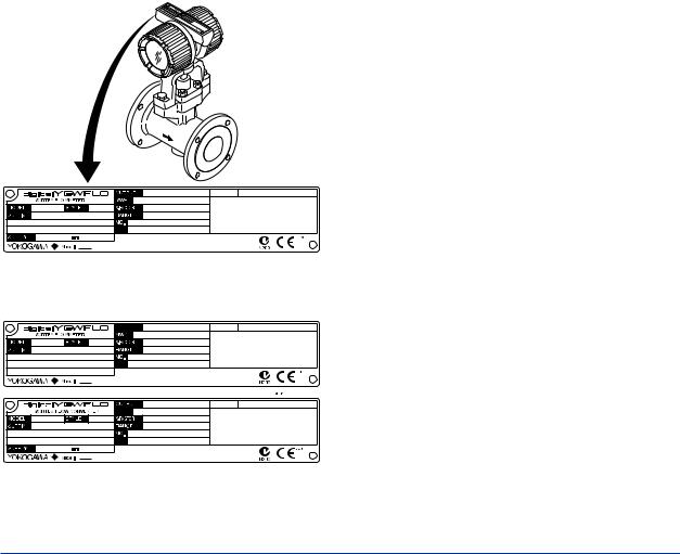
2.1Checking Model and Specifications
The model and important specifications are indicated on the name plate attached to the case. Verify that they are the same as those specified in the original order, refer to Chapter 13 “GENERAL SPECIFICATIONS .” In any correspondence, always give model (MODEL) and serial number (NO.) from the name plate.
4 ~ 20mA DC / PULSE |
TAG NO. |
MPa at 38°C |
|
*1) |
|
10.5 ~ 42V DC |
3UA |
*2) |
|
2.2Transportation and Storage Precautions
If the instrument is to be stored for a long period of time after delivery, observe the following points.
(1)The instrument should be stored in its original packing condition in the storage location.
(2)Select a storage location that fulfils the following conditions:
•A place where it will not be exposed to rain or water
•A place subject to minimal vibrations or shocks
•Temperature and humidity levels should be as follows:
Temperature:-40 to +80°C
Humidity:5 to 100% RH (no condensation) The preferred ambient temperature and humidity levels are +25°C and approximately 65% RH.
(3)If the digitalYEWFLO vortex flowmeter is transferred to the installation site and stored without being installed, its performance may be impaired due to the infiltration of rainwater and so forth. Be sure to install and wire the digitalYEWFLO vortex flowmeter as soon as possible after transferring it to the installation location.
(4)The vortex flowmeter is a heavy instrument. Be careful that no damage is caused to personnel through accidentally dropping it, or by exerting excessive force on the vortex flowmeter. When moving the vortex flowmeter, always use a trolley and have at least two people carry it.
F0201.ai
Figure 2.1(a) Example of Name Plate for Integral Type
TAG NO. |
MPa at 38°C |
*1) |
3WA |
*2) |
4 ~ 20mA DC / PULSE |
TAG NO. |
*1) |
|
10.5 ~ 42V DC |
3YA |
*2) |
|
|
F0202.ai |
Figure 2.1(b) Example of Name Plate for Remote Type
*1): K factor at + 15°C
*2): The product - producing country.
IM 01F06A00-01EN
<3. INSTALLATION> |
3-1 |
3.INSTALLATION
 WARNING
This instrument must be installed by expert engineer or skilled personnel. The procedures described in this chapter are not permitted for operators.
3.1Installation Precautions
(1)Ambient Temperature
Avoid an area which has wide temperature variations. When the installation area is subjected to heat radiation from process plant, ensure adequate heat prevention or ventilation.
(2)Atmospheric Conditions
Avoid installing the vortex flowmeter in a corrosive atmosphere. When the vortex flowmeter must be installed in a corrosive atmosphere, adequate ventilation must be provided
(3)Mechanical Shock or Vibration
The vortex flowmeter is of sturdy construction, but select an area subject to minimize mechanical vibration or impact shock. If
the flowmeter is subject to vibrations, it is recommended that pipeline supports to be provided as shown in Figure 3.1.
digitalYEWFLO Vortex Flowmeter
Pipeline
Pipeline Support
F0301.ai
Figure 3.1 Example of Pipeline Support
(4) Precautions Regarding Piping
(a)Ensure that the process connector bolts are tightened firmly.
(b)Ensure that no leak exists in the process connection pipeline.
(c)Do not apply a pressure higher than the specified maximum working pressure.
(d)Do not loosen or tighten the flange mounting bolts when the assembly is pressurized.
(e)Handle the vortex flowmeter carefully when measuring dangerous liquids, so that the liquids do not splash into eyes or on face. When using dangerous gases, be careful not to inhale them.
(5) Other Considerations
•Choose a location where is sufficient clearance around digitalYEWFLO exist to allow such work as routine inspections.
•Choose a location that ensures easy wiring and piping.
3.2Piping Precautions
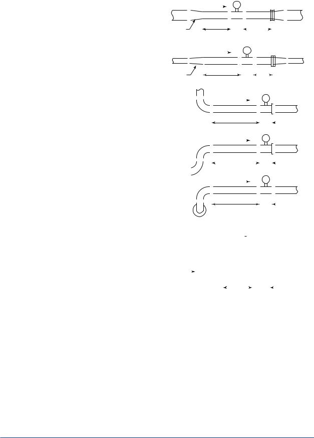
Straight Pipe Length and Recommendations
Refer to Table 3.1 about Valve Position and Straight Pipe Length and so on.
●Piping support
Typical vibration immunity level is 1G for normal piping condition.Piping support should be fixed in case of over 1G vibration level.
●Installation direction
If a pipe is always filled with liquids, the pipe can be installed vertically or at inclined angle.
●Adjacent pipes
The process pipline inner diameter should be larger than the digitalYEWFLO inner diameter.
Use the following adjacent pipe.
Model Code |
Adjacent Pipe |
|
DY015 up to DY050 |
Sch40 |
|
or larger inner |
||
DY025/R1 up to DY080/R1 |
||
diameter than |
||
DY040/R2 up to DY100/R2 |
||
Sch40 |
||
|
||
DY080 up to DY400 |
Sch80 |
|
or larger inner |
||
DY100/R1 up to DY200/R1 |
||
diameter than |
||
DY150/R2 up to DY200/R2 |
||
Sch80 |
||
|
IM 01F06A00-01EN
<3. INSTALLATION> |
3-2 |
Table 3.1 (a) Straight pipe length and recommendations (1)
D: Nominal diameter (mm)
Description |
|
|
|
|
|
|
|
|
|
|
|
|
|
|
|
Figure |
|
|
|
|
|
|
|
|
|
|
|
|
|
|
|
|
|
|
|||||||||
Reducer pipe: |
|
|
|
|
|
|
|
|
|
|
|
|
|
digitalYEWFLO |
|||||||||||||||||||||||||||||
Ensure the upstream straight pipe length to be 5D or more, and the |
|
|
|
|
|
|
|
|
|
|
Flow |
|
|
|
|
|
|
|
|
|
|
|
|
|
|
|
|
|
|
||||||||||||||
downstream straight pipe length to be 5D or more for per reducer |
|
|
|
|
|
|
|
|
|
|
|
|
|
|
|
|
|
|
|
|
|
|
|
|
|
|
|
|
|
|
|
|
|
|
|
|
|
|
|
|
|
|
|
|
|
|
|
|
|
|
|
|
|
|
|
|
|
|
|
|
|
|
|
|
|
|
|
|
|
|
|
|
|
|
|
|
|
|
|
|
|
|
|
|
|
|
|
pipe. |
|
|
|
|
|
|
|
|
|
|
|
|
|
|
|
|
|
|
|
|
|
|
|
|
|
|
|
|
|
|
|
|
|
|
|
|
|
|
|
|
|
|
|
|
|
|
|
|
|
|
|
|
5D or more |
|
|
|
|
|
|
|
|
|
|
5D or more |
|
|
|
|
|
|
|||||||||||||||||
|
Reducer |
|
|
|
|
|
|
|
|
|
|
|
|
|
|
|
|
|
|||||||||||||||||||||||||
|
|
|
|
|
|
|
|
|
|
|
|
|
|
|
|
|
|
|
|
|
|
|
|
|
|
|
|
|
|
|
|
|
|
|
|
|
|
||||||
|
|
|
|
|
|
|
|
|
|
|
|
|
|
|
|
|
|
|
|
|
|
|
|
|
|
|
|
|
|
|
|
|
|
|
|
|
|
|
|
|
|
|
|
Expander pipe: |
|
|
|
|
|
|
|
|
|
|
|
|
|
|
|
|
|
digitalYEWFLO |
|||||||||||||||||||||||||
Ensure the upstream straight pipe length to be 10D or more, and |
|
|
|
|
|
|
|
|
|
|
|
|
Flow |
|
|
|
|
|
|
|
|
|
|
|
|
|
|
|
|
|
|
||||||||||||
the downstream straight pipe length to be 5D or more for per |
|
|
|
|
|
|
|
|
|
|
|
|
|
|
|
|
|
|
|
|
|
|
|
|
|
|
|
|
|
|
|
|
|
|
|
|
|
|
|
|
|
|
|
|
|
|
|
|
|
|
|
|
|
|
|
|
|
|
|
|
|
|
|
|
|
|
|
|
|
|
|
|
|
|
|
|
|
|
|
|
|
|
|
|
|
|
|
expander pipe. |
|
|
|
|
|
|
|
|
|
|
|
|
|
|
|
|
|
|
|
|
|
|
|
|
|
|
|
|
|
|
|
|
|
|
|
|
|
|
|
|
|
|
|
|
Expander |
|
|
|
|
10D or more |
|
|
|
|
|
|
|
|
|
|
|
|
|
|
|
|
|
|
|
||||||||||||||||||
|
|
|
|
|
|
|
|
|
|
|
|
|
|
|
|
|
|
|
|
|
|
|
|
|
|
|
|
|
|
|
|
|
|
|
|
|
|
||||||
|
|
|
|
|
|
|
|
|
|
|
|
|
|
|
|
|
|
|
|
|
|
|
|
|
|
|
|
|
|
5D or more |
|||||||||||||
|
|
|
|
|
|
|
|
|
|
|
|
|
|
|
|
|
|
|
|
|
|
|
|
|
|
|
|
|
|
|
|
|
|
|
|
|
|
|
|
|
|
|
|
Bent pipe and straight pipe length: |
1. |
|
|
|
|
|
|
|
|
|
|
|
|
|
|
|
|
|
|
|
|
|
|
|
|
|
|
|
|
digitalYEWFLO |
|||||||||||||
1. Single bent pipe |
|
|
|
|
|
|
|
|
|
|
|
|
|
|
|
|
|
|
Flow |
|
|
|
|
|
|
|
|
|
|
|
|
|
|
|
|
|
|
||||||
|
|
|
|
|
|
|
|
|
|
|
|
|
|
|
|
|
|
|
|
|
|
|
|
|
|
|
|
|
|
|
|
|
|
|
|
|
|
|
|
|
|
|
|
|
|
|
|
|
|
|
|
|
|
|
|
|
|
|
10D or more |
|
|
|
|
|
|
|
|
|
|
|
|
|
|
|
5D or more |
||||||||||||
|
|
|
|
|
|
|
|
|
|
|
|
|
|
|
|
|
|
|
|
|
|
|
|
|
|
|
|
|
|
||||||||||||||
|
|
|
|
|
|
|
|
|
|
|
|
|
|
|
|
|
|
|
|
|
|
|
|
|
|
|
|
|
|
||||||||||||||
|
|
|
|
|
|
|
|
|
|
|
|
|
|
|
|
|
|
|
|
|
|
|
|
|
|
|
|
|
|
|
|
|
|
|
|
|
|
|
|
|
|
|
|
|
|
|
|
|
|
|
|
|
|
|
|
|
|
|
|
|
|
|
|
|
|
|
|
|
|
|
|
|
|
digitalYEWFLO |
|||||||||||||
2. Double bent pipe; coplanar |
2. |
|
|
|
|
|
|
|
|
|
|
|
|
|
|
|
|
|
Flow |
|
|
|
|
|
|
|
|
|
|
|
|
|
|
|
|
|
|
||||||
|
|
|
|
|
|
|
|
|
|
|
|
|
|
10D or more |
|
|
|
|
|
|
|
|
|
|
|
|
|
|
|
5D or more |
|||||||||||||
|
|
|
|
|
|
|
|
|
|
|
|
|
|
|
|
|
|
|
|
|
|
|
|
|
|
|
|
|
|
||||||||||||||
|
|
|
|
|
|
|
|
|
|
|
|
|
|
|
|
|
|
|
|
|
|
|
|
|
|
|
|
|
|
|
|
|
|
|
|
|
|
|
|
|
|
|
|
|
|
|
|
|
|
|
|
|
|
|
|
|
|
|
|
|
|
|
|
|
|
|
|
|
|
|
|
|
|
digitalYEWFLO |
|||||||||||||
3. Double bent pipe; non coplanar |
3. |
|
|
|
|
|
|
|
|
|
|
|
|
|
|
|
|
|
Flow |
|
|
|
|
|
|
|
|
|
|
|
|
|
|
|
|
|
|
||||||
|
|
|
|
|
|
|
|
|
|
|
|
|
|
|
|
|
|
|
|
|
|
|
|
|
|
|
|
|
|
|
|
|
|
||||||||||
|
|
|
|
|
|
|
|
|
|
|
|
|
20D or more |
|
|
|
|
|
|
|
|
|
|
|
|
|
|
|
5D or more |
||||||||||||||
|
|
|
|
|
|
|
|
|
|
|
|
|
|
|
|
|
|
|
|
|
|
|
|
|
|
|
|
|
|||||||||||||||
|
|
|
|
|
|
|
|
|
|
|
|
|
|
|
|
|
|
|
|
|
|
|
|
|
|
|
|
|
|
||||||||||||||
|
|
|
|
|
|
|
|
|
|
|
|
|
|
|
|
|
|
|
|
|
|
|
|
|
|
|
|
|
|
||||||||||||||
|
|
|
|
|
|
|
|
|
|
|
|
|
|
|
|
|
|
|
|
|
|
|
|
|
|
|
|
|
|
|
|
|
|
|
|
|
|
|
|
|
|
|
|
Valve position and straight pipe length: |
|
|
|
|
|
|
|
|
|
|
|
|
|
|
|
|
|
|
|
|
|
|
|
|
|
|
|
|
|
|
|
|
|||||||||||
|
|
|
|
|
|
|
|
|
|
|
|
|
|
|
|
|
digitalYEWFLO |
||||||||||||||||||||||||||
Install the valve on the downstream side of the flowmeter. |
|
|
|
|
|
|
|
|
|
|
|
|
|
|
|
|
|
|
|
|
|
|
|
|
|
|
|
|
|
|
|
|
|
|
|
|
|
|
|
|
|
|
|
The upstream straight pipe length dependent on the element |
|
|
|
|
|
|
|
|
|
|
|
|
|
|
|
|
|
|
|
|
|
|
|
|
|
|
|
|
|
|
|
|
|
|
|
|
|
|
|
|
|
|
|
located on the upstream such as reducer/expander, bent and etc., |
|
Refer to each element above for |
|
|
|
|
|
|
|
|
|
|
|
|
|
|
|
|
|
|
|
|
|
|
|
|
|||||||||||||||||
|
|
|
|
|
|
|
|
|
|
|
|
|
|
|
|
|
|
|
|
|
|
||||||||||||||||||||||
refer to description as above. Keep 5D or more for downstream |
|
straight pipe run. |
|
|
|
|
|
|
|
|
|
|
|
|
|
|
|
|
|
|
|
|
|
|
|
|
|||||||||||||||||
|
|
|
|
|
|
|
|
|
|
|
|
|
|
|
|
|
|
|
|
|
|
||||||||||||||||||||||
straight pipe length. |
|
|
|
|
|
|
|
|
|
|
|
|
|
|
|
|
|
|
|
|
|
|
|
|
|
|
|
|
|
|
|
|
|
|
|
|
|
|
|
|
|
|
|
|
|
|
|
|
|
|
|
|
|
|
|
|
|
|
|
|
|
|
|
|
|
|
|
|
|
|
|
|
|
|
|
|
|
|
|
|
|
|
|
|
|
|
|
In case the valve has to be installed on the upstream of the |
|
|
Flow |
|
|
|
Valve |
|
digitalYEWFLO |
||||||||||||||||||||||||||||||||||
flowmeter, ensure the upstream straight pipe length to be 20D or |
|
|
|
|
|
|
|
|
|
|
|
|
|
|
|
|
|
|
|
|
|
|
|
|
|
|
|
|
|
|
|
|
|
|
|
|
|
|
|
|
|
|
|
more, and the downstream straight pipe length be 5D or more. |
|
|
|
|
|
|
|
|
|
|
|
|
|
|
|
|
|
|
|
|
|
|
|
|
|
|
|
|
|
|
|
|
|
|
|
|
|
|
|
|
|
|
|
|
|
|
|
|
|
|
|
|
|
|
|
|
|
|
|
|
|
|
|
|
|
|
|
|
|
|
|
|
|
|
|
||||||||||||
|
|
|
|
|
|
|
|
|
|
|
|
|
|
20D or more |
|
|
|
|
|
|
|
5D or more |
|||||||||||||||||||||
|
|
|
|
|
|
|
|
|
|
|
|
|
|
|
|
|
|
|
|
|
|
|
|
|
|
|
|
|
|
|
|
|
|
|
|||||||||
|
|
|
|
|
|
|
|
|
|
|
|
|
|
|
|
|
|
|
|
|
|
|
|
|
|
|
|
|
|
|
|
|
|
|
|
|
|
|
|
|
|
|
|
IM 01F06A00-01EN
|
<3. INSTALLATION> |
3-3 |
||||||||||
Table 3.1 (b) Straight pipe length and recommendations (2) |
|
|
|
|
|
|
|
|
|
|
|
|
D: Nominal diameter (mm) |
|
|
|
|
|
|
|
|
|
|
|
|
|
|
|
|
|
|
|
|
|
|
|
|
|
Description |
Figure |
|
||||||||||
Fluid vibration: |
|
digitalYEWFLO |
|
|||||||||
|
|
|
||||||||||
For a gas line which uses a position-type or roots-type blower |
|
|
|
|
|
|
|
|
|
|
|
|
compressor or a high-pressure liquid line (about 1MPa or more) |
|
|
|
|
|
|
|
|
|
|
|
|
which uses piston-type or plunger-type pump, fluid vibrations may |
|
|
|
|
|
|
|
|
|
|
|
|
be produced. |
|
|
|
|
|
|
|
|
|
|
|
|
In these case, install valve on the upstream side of digitalYEWFLO. |
|
digitalYEWFLO |
|
|||||||||
For inevitable fluid vibration, put a vibration damping device such |
|
|
||||||||||
|
|
|
|
|
|
|
|
|
|
|
|
|
as throttling plate or expansion section in the upstream side of |
|
|
|
|
|
|
|
|
|
|
|
|
digitalYEWFLO. |
|
|
|
|
|
|
|
|
|
|
|
|
|
|
|
|
|
|
|
|
|
|
|
|
|
|
|
|
|
|
|
|
|
|
|
|
|
|
Piston-type or plunger pump: |
|
|
|
|
|
|
|
|
|
|
|
|
Install the accumulator on the upstream side of digitalYEWFLO to |
|
|
|
|
|
|
|
|
|
|
|
|
reduce fluid vibrations. |
|
digitalYEWFLO |
|
|
||||||||
|
|
|
|
|
|
|
|
|
|
|
|
|
|
|
|
|
|
|
|
|
|
|
|
|
|
|
|
|
|
|
|
|
|
|
|
|
|
|
Valve positon (T-type piping exist):
When pulsation causes by a T-type piping exist, install the valve on |
|
|
Relocating |
digitalYEWFLO |
|||||||||||||||||
the upstream of the flowmeter. |
|
|
|
|
|
||||||||||||||||
Flow |
|
|
|
|
|
|
|
|
|
|
|
|
Valve (Off) |
||||||||
Example: As shown in the figure, when the valve V1 is turned off, |
|
|
|
|
|
|
|
|
|
|
|
|
|||||||||
|
|
|
|
|
|
|
|
|
|
|
|
|
|
|
|
|
|
|
|
|
|
the fluid flow throught B as to meter A the flow is zero. But due to |
B |
|
|
|
|
|
|
|
|
|
|
|
|
|
|
|
|
|
|
|
|
the pulsating pressure is detected, the meter is zero point become |
|
|
|
|
|
|
|
|
|
|
|
|
|
|
|
|
|
|
|
|
|
|
|
|
|
|
|
|
|
|
|
|
|
|
|
|
|
|
|
|
|
|
|
|
|
|
|
|
|
|
|
|
|
|
|
|
|
|
|
|
|
|
|
|
|
fluctuating. To avoid this, change the valve V1 location to V1'. |
|
|
|
V1’ |
|
|
|
|
|
|
|
|
|
|
|
|
|
V1 |
|
||
|
|
|
|
|
|
|
|
|
|
|
|
|
|
|
|
|
|||||
|
|
|
|
|
|
|
|
|
|
|
|
|
|
|
|
|
|
|
|
|
|
Note: In case of the Reduced Bore Type, moisture may be |
|
|
|
|
|
|
|
|
|
A |
|||||||||||
|
|
|
|
|
|
|
|
|
|
|
|
|
|
|
|
|
|
|
|
|
|
remained upstream of the flowmeter. Drain it appropriately. |
|
|
|
|
|
|
|
|
|
|
|
|
|
|
|
|
|
|
|
|
|
Pressure and Temperature Taps: |
|
|
|
|
|
|
|
|
|
|
|
|
|
|
|
|
|
|
|
|
|
|
|
|
|
|
|
|
|
Pressure tap |
|
|
|
|
|
||||||
Pressure tap outlet: install this tap between 2D and 7D on the |
|
|
|
|
|
|
|
|
|
|
|
|
|
|
|
|
|
|
|
|
|
|
|
|
|
|
|
|
|
|
|
|
|
|
|
|
|
|
|
|
|
|
|
|
|
digitalYEWFLO |
|
|
Temperature tap |
|
||||||||||||
downstream side of a flowmeter. |
|
|
|
|
|
|
|
|||||||||||||
|
|
|
|
|
|
|
|
|
|
|
|
|
|
|
|
|||||
|
|
|
|
|
|
|||||||||||||||
Temperature tap outlet: install this on the downstream side 1D to |
|
|
|
|
|
|
|
|
|
|
|
|
|
|
|
|
|
|
|
|
|
|
|
Upstream |
|
|
|
|
|
|
|
|
|
|
|
|
|
|
|
||
2D away from a pressure tap. |
|
|
|
|
|
|
|
|
|
|
|
|
|
|
|
|
|
|
||
|
|
|
|
|
|
|
|
|
|
|
|
|
|
|
|
|
|
|
|
|
|
|
|
|
|
|
|
|
|
|
|
|
|
|
|
|
|
|
|
||
|
Flow |
|
|
|
|
|
|
|
|
|||||||||||
|
|
|
|
|
|
|
|
|
|
|
|
|
|
|
|
|
|
|
|
|
|
|
|
|
|
|
|
|
|
|
|
|
|
|
|
|
|
downstream |
|||
|
|
|
|
|
|
|
|
|
|
|
|
|
|
|
|
|
||||
|
|
|
|
|
|
|
|
|
|
|
2 to 7D |
|||||||||
|
|
|
|
|
|
|
|
|
|
|
|
1 to 2D |
||||||||
|
|
|
|
|
|
|
|
|
|
|
|
|
|
|
|
|
|
|
|
|
Mounting Gasket: |
|
|
|
|
|
digitalYEWFLO |
|
|
|
|
|
|
|
|
||||||
Avoid mounting gaskets which protrude into the pipe line. This may |
|
|
|
|
|
|
|
|
|
|
|
|
|
|
|
|
|
|
|
|
cause inaccurate readings. |
|
|
|
|
|
|
|
|
|
|
|
|
|
|
|
|
|
|
|
|
Use the gaskets with bolt holes, even if digitalYEWFLO is the wafer |
|
|
|
|
|
|
|
|
|
|
|
|
|
|
|
|
|
|
|
|
type. |
|
|
|
|
|
|
|
|
|
|
|
|
|
|
|
|
|
|
|
|
When using a spiral gasket (without bolt holes), confirm the size |
|
|
|
|
|
|
|
|
|
|
|
|
|
|
|
|
|
|
|
|
with the gasket -manufacturer, as standard items may not be used |
|
|
|
|
|
|
|
|
|
|
|
|
|
|
|
|
|
|
|
|
|
|
|
|
|
|
|
|
|
|
|
Pipeline Flange |
|
|
|||||||
for certain flange ratings. |
|
|
|
|
|
|
|
|
|
|
|
|
||||||||
|
|
|
|
|
|
|
|
|
|
|
|
|
|
Pipeline |
|
|
|
|||
|
|
|
|
|
|
|
|
|
|
|
|
|
|
|||||||
|
|
|
|
No good |
|
|
|
|
|
|
|
|
||||||||
|
|
|
|
|
|
|
|
|
|
|
|
|
|
|
|
|
|
|
|
|
|
|
|
|
|
|
|
|
|
|
|
|
|
|
|
|
|
|
|
|
|
IM 01F06A00-01EN
<3. INSTALLATION> |
3-4 |
Table 3.1 (c) Straight pipe length and recommendations (3)
Description |
Figure |
|
|
Heat-Insulation: |
digitalYEWFLO |
digitalYEWFLO |
|
When an integral-type flowmeter or a remote type detector is |
|
|
|
installed and the pipe carrying higt-temperature fluids is heat- |
Bracket |
Nozzle |
|
insulated, do not wrap adiabatic materials around the installation |
Heat-Insulator |
Heat-Insulator |
|
the bracket (DY015 to DY100) or the nozzle (DY150 to DY400) of |
|||
|
|
||
the converter. |
|
|
Note: Refer to Section 3.4 "Cryogenic and High Process
Temperature Version Insulation" and install it rightly.
[DY015 to DY100] [DY150 to DY400]
Flushing of the pipe line: |
digitalYEWFLO |
|||||||
Flush and clean scale, incrustation and sludge on the inside of |
|
|
|
|||||
pipe for newly installed pipe line and repaired pipe line before the |
|
|
|
|
|
|
|
|
|
|
|
|
|
|
|
|
|
operation. For flushing, the flow should flow through bypass-piping |
|
|
|
|
|
|
|
|
to avoid damaging the flowmeter. If there is no bypass-piping, |
|
|
|
|
|
|
|
|
|
|
|
|
|
||||
install short pipe instead of the flowmeter. |
|
|
|
|||||
|
|
|
|
|
|
|
|
|
|
|
|
|
|
|
|
|
Short pipe |
|
|
|
|
|
|
|
|
|
Mounting Precautions
 WARNING
In case of high process temperature, care should be taken not to burn yourself because the surface of body and case reach a high temperature.
(1) Gas or Steam Measuring Precautions
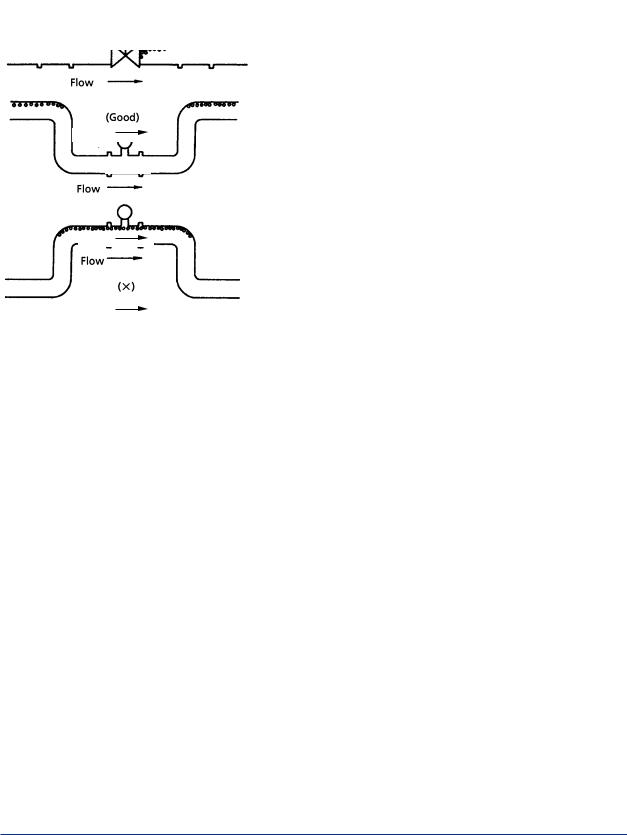
•Piping to Prevent Standing Liquid
Mount digitalYEWFLO in a vertical pipeline to avoid liquid traps. When digitalYEWFLO is installed horizontally, raise that part of the pipeline in which the digitalYEWFLO is installed.
(Good)
(Good) |
|
|
|
|
|
|
|
|
Flow |
|
|
|
|
|
|
|
|
|
||
|
|
|
|
|
|
|
Flow
(No Good)
Flow
F0302.ai
(2)Liquid Measurement Precautions
To insure accurate measurement, the digitalYEWFLO must always have a full pipe.
•Piping Requirements for Proper Operation Allow the flow to flow against gravity. When the flow is moving with gravity, lift the downstream pipe length above the digitalYEWFLO installation level to maintain full pipeline.
Flow
|
|
|
|
|
(No Good) |
|
|
(No Good) |
|
|
|
|
|
|
|
||||
|
|
|
|
|
|
|
|
|
Flow |
|
|
|
|
|
|
|
|||
|
|
|
|
|
|
|
|
|
|
|
|
|
|
|
|||||
|
|
|
|
|
|
|
|
|
|
|
|
|
|
|
|
|
|
|
|
(Good) |
|
|
|
|
|
|
|
|
|
|
|
|
|
||||||
|
|
|
|
|
|
|
|
|
|
|
|
|
|
|
|
|
|
|
|
|
|
|
|
|
|
|
h h>0 |
|
|
|
|
|
|
|
|
|
|
|
|
|
|
|
|
|
|
|
|
|
(Good) |
|
|
|
|
|
|
|
|
||
|
|
|
|
|
|
|
|
|
|
|
|
|
|
|
|
|
|||
|
|
|
|
|
|
|
|
|
|
|
|
|
|
|
|
|
|
||
|
|
|
|
|
|
|
|
|
|
|
|
|
|
|
|
|
|
|
|
|
|
|
|
|
|
|
|
|
|
|
|
|
|
|
|
|
|
|
|
|
|
|
|
|
|
|
|
|
|
|
|
|
|
|
|
|
h |
|
|
|
|
|
|
|
|
|
|
|
|
|
|
|
|
|
|
|
|
||
|
|
Flow |
|
|
|
|
Flow |
|
|
|
|
|
h>0 |
|
|||||
|
|
|
|
|
|
|
|
|
|
F0303.ai |
|||||||||
|
|
|
|
|
|
|
|
|
|
|
|
|
|||||||
|
|
|
|
|
|
|
|
|
|
|
|
||||||||
|
|
|
|
|
|
|
|
|
|
|
|
|
|
|
|
||||
IM 01F06A00-01EN
<3. INSTALLATION> |
3-5 |
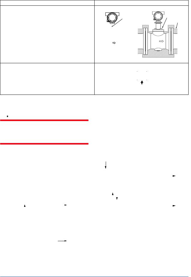
•Piping for Avoiding Bubbles
Flows containing both gas and liquid cause problems. Avoid gas bubbles in a liquid flow. Piping should be carried out to avoid bubble generation.
Install the valve on the downstream side of the flowmeter because pressure drop across the control valve may cause gas to come out of the solution.
|
|
|
|
|
(Good) |
|
|
(No Good) |
|
|
Control |
|
||
|
|
Value |
|
|
Flow
(Good)
Flow
Flow
(No Good)
F0304.ai
(3) Multi-Phase Flow
digitalYEWFLO can measure gas, liquid and steam when there is no change in state. However, accurate measurement of mixed flows (e.g. gas and liquid) is not possible.
(No Good)
Mist flow
(No Good)
Liquid
Flow
Stratified flow (No Good)
Gas Flow
Bubble flow |
F0305.ai |
|
(4) Pipeline Diameter and digitalYEWFLO
The process pipeline inner diameter should be slightly larger than the vortex flowmeter inner diameter, schedule 40 or lower pipe should be used for 1/2 to 2 inch flowmeters and schedule 80 or lower pipes for 3 to 16 inch flowmeters.
|
(No Good) |
|
|
|
|
(Good) |
|
||||||||||
|
|
|
|
|
|
|
|
|
|
|
|
|
|
|
|
|
|
|
|
|
|
|
|
|
|
|
|
|
|
|
|
|
|
|
|
|
|
|
|
|
|
|
|
|
|
|
|||||||
|
|
|
|
D2 |
|
|
|
|
|
|
D2 |
|
|
||||
D1 |
|
|
|
|
D1 |
|
|||||||||||
|
|
|
|
|
|
|
|
|
|
|
|
|
|
|
|
|
|
|
|
|
|
|
|
|
|
|
|
|
|
|
|
|
|
|
|
|
|
|
|
|
|
|
|
|
|
|
|
|
|
|
|
|
|
|
|
|
|
|
|
|
|
|
|
|
|
|
|
|
|
|
|
|
|
|
|
|
|
|
|
|
|
|
|
|
|
|
|
|
|
|
|
|
|
|
|
|
|
|
|
||||||||
|
|
|
D1 < D2 |
|
|
|
|
|
|
|
|||||||
|
|
|
|
|
|
|
|
D1 D2 |
|
||||||||
F0306.ai
(5)Waterproof Construction
The vortex flowmeter is of IP67, Type 4X, JIS C 0920 watertight protection. However, it cannot be used under water.
3.3Maintenance of Piping
(1) Pipe cleaning
•Flushing of pipe line (Cleaning)
Flush and clean scale, incrustation and sludge on the inside of pipe wall for newly installed pipe line and repaired pipe line before the operation.
•Fluid Carrying Solids
Do not measure fluids that carry solids (e.g. sand and pebbles). Make sure users periodically remove solids adhering to the vortex shedder.
•Obstruction of flow fluids may cause to make a chemical reaction and the fluid will be
crystallized and hardened, and be deposited on the pipe wall and shedder bar.
In those cases, clean shedder bar.
(2)Bypass piping
Bypass piping is convenient for the maintenance of digitalYEWFLO (vortex shedder cleaning, etc.).
Bypass shut-off valve
digitalYEWFLO
Flow 
Upstream shut-off valve |
|
Downstream shut-off valve |
|
|
F0307.ai |
IM 01F06A00-01EN
<3. INSTALLATION> |
3-6 |
3.4Cryogenic and High Process Temperature Version Insulation
When you are using Cryogenic and High Process Temperature version of digitalYEWFLO Vortex Flowmeter (Option code: /HT, /LT), refer to following contents.
Installing Cryogenic Version
For cryogenic applications, use stainless steel mounting bolts and nuts to install the flowmeter. These can be ordered separately from YOKOGAWA. Cover the flowmeter body with heat insulating material so that the flowmeter can be maintained at ultra-low temperatures.
Maintenance for Cryogenic Applications
DY/LT uses special materials that produce vortex flowmeter for cryogenic applications. When you are replacing a shedder bar, specify Cryogenic Version shedder bar. To avoid condensing in the terminal box, ensure that the wire connecting port is well sealed.
Bracket
Cold insulating material
F0308.ai
Installing High Process Temperature Version
Installation of the flowmeter is the same as the standard type. Cover the flowmeter body with heat insulating material following instruction of “CAUTION”.
 CAUTION
Keep the upper limit of heat insulating material to prevent overheating of the terminal box.
Seal the Heat-Insulator to avoid hot-air leakage.
|
|
|
|
|
|
|
|
|
|
|
|
|
|
|
|
|
|
|
|
|
|
|
|
|
|
|
|
|
|
|
|
|
|
|
|
|
|
|
|
|
|
|
|
|
|
|
|
|
|
|
|
|
|
|
|
|
|
|
|
|
|
|
|
|
|
|
|
|
|
|
|
|
|
|
|
|
|
|
|
|
|
|
|
|
|
|
|
|
|
|
|
|
|
|
|
|
|
|
|
|
|
|
|
|
|
|
|
|
|
|
|
|
|
|
|
|
|
|
|
|
|
|
|
|
|
|
|
|
|
|
|
|
|
|
|
|
|
|
|
|
|
|
|
|
|
|
|
|
|
|
|
|
|
|
|
|
|
|
|
|
|
|
|
|
|
|
|
|
|
|
|
|
|
|
|
|
|
|
|
|
|
|
|
|
|
|
|
|
|
|
|
|
|
|
|
|
|
|
|
|
|
|
|
|
|
|
|
|
|
|
|
|
|
|
|
|
|
|
|
|
|
|
|
|
|
|
|
|
|
|
|
|
|
|
|
|
|
|
|
|
|
|
|
|
|
|
|
|
|
|
|
|
|
|
|
50mm min. |
|
|
|
|
|
|
|
|
|
|
|
|
|
50mm min. |
|
UPPER LIMIT OF |
|
|
|
|
|
|
|
|
|
|
|
|
UPPER LIMIT OF |
|
|
|
|
|
|
|
|
|
|
||||||||||
Heat-Insulator |
|
|
|
|
|
|
|
|
|
|
|
|
Heat-Insulator |
|
|
|
|
|
|
|
|
|
|||||||||||
|
|
|
|
|
|
|
|
|
|
|
|
||||||||||||||||||||||
|
|
|
|
|
|
|
|
|
|
|
|
|
|
|
|
|
|
|
|
|
|
|
|
|
|
|
|
|
|
|
|
|
|
|
|
|
|
|
|
|
|
|
|
|
|
|
|
|
|
|
|
|
|
|
|
|
|
|
|
|
|
|
|
|
|
|
|
|
|
|
|
|
|
|
|
|
|
|
|
|
|
|
|
|
|
|
|
|
|
|
|
|
|
|
|
|
|
|
|
|
|
|
|
|
|
|
|
|
|
|
|
|
|
|
|
|
|
|
|
|
|
|
|
|
|
|
|
|
|
|
|
|
|
|
|
|
|
|
|
|
|
|
|
|
|
|
|
|
|
|
|
|
|
|
|
|
|
|
|
|
|
|
|
|
|
|
|
|
|
|
|
|
|
|
|
|
|
|
|
|
|
|
|
|
|
|
|
|
|
|
|
|
|
|
|
|
|
|
|
|
|
|
|
|
|
|
|
|
|
|
|
|
|
|
|
|
|
|
|
|
|
|
|
|
|
|
|
|
|
|
|
|
|
|
|
|
|
|
|
|
|
|
|
|
|
|
|
|
|
|
|
|
|
|
|
|
|
|
|
|
|
|
|
|
|
|
|
|
|
|
|
Nominal Size: 100mm or under
Nominal Size: 150mm or over
F0309.ai
Maintenance for High Process Temperature Applications
DY/HT uses special materials that produce vortex flowmeter for High Process Temperature applications When you are replacing a shedder bar or a gasket, specify High Process Temperature Version.
3.5Mounting Procedures
 WARNING
The Vortex Flowmeter is a heavy instrument. Please be careful to prevent persons from injuring whin it is handled.
Before installing the instrument verify the following. The direction of flow should match to the arrow mark on the instrument body. When changing the orientation of the terminal box, refer to Chapter 11 “MAINTENANCE.”
1.Installation of Vortex flowmeter of the wafer and flange type is shown in Table 3.3.
When installing the wafer type vortex flowmeter, it is important to align the instrument bore with the inner diameter of the adjacent piping.
To establish alignment, use the four collars supplied with the instrument.
IM 01F06A00-01EN
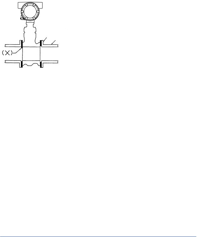
<3. INSTALLATION> |
3-7 |
•Four collars are supplied for 1/2 inch (15mm) to 1- 1/2inch (40mm), 2 inch of JIS 10K or ANSI class 150, and 3 inch of ANSI class 150. Install the instrument as illustrated in Table 3.3.
•If the adjacent flanges have eight bolt holes, insert the stud bolts in the holes on the instrument shoulder.
•Stainless steel stud bolts and nuts are available on order. When they are to be supplied by the user, refer to Table 3.2 for stud bolt length. Gaskets must be supplied by the user.
Pipeline Flange
Pipeline
F0311.ai
2.Avoid mounting gaskets which protrude into the pipeline. This may cause inaccurate readings. Use gaskets with bolt holes, even if digitalYEWFLO is of the wafer type.
When using a spiral gasket (without bolt holes), confirm the size with the gasket-manufacturer, as standard items may not be used for certain flange ratings.
Table 3.2 Flange Rating
Size |
|
Major Diameter of |
|
|
|
External Threed |
Length |
||
mm |
Flange Rating |
|||
of Stud Bolt d |
(mm) |
|||
(inch) |
|
|||
|
(mm) |
|
||
|
|
|
||
15mm |
JIS 10K, 20K/DIN 10, |
|
|
|
(1/2B) |
16,25,40 |
12 |
160 |
|
|
JIS 40K |
16 |
160 |
|
|
ANSI 150, 300, 600 |
12.7 |
155 |
|
25mm |
JIS 10K, 20K, 40K |
16 |
160 |
|
(1B) |
ANSI 150 |
12.7 |
155 |
|
|
ANSI 300, 600 |
15.9 |
160 |
|
|
DIN 10, 16, 25, 40 |
12 |
160 |
|
40mm |
JIS 10K, 20K/DIN 10, |
|
|
|
(1-1/2B) |
16, 25, 40 |
16 |
160 |
|
|
JIS 40K |
20 |
170 |
|
|
ANSI 150 |
12.7 |
155 |
|
|
ANSI 300, 600 |
19.1 |
170 |
|
50mm |
JIS 10K, 20K, 40K/ DIN |
|
|
|
(2B) |
10, 16, 25, 40 ANSI |
16 |
200 |
|
|
150, 300, 600 |
15.9 |
200 |
|
80mm |
JIS 10K/DIN 10, 16, |
|
|
|
(3B) |
25, 40 |
16 |
220 |
|
|
JIS 20K, 40K |
20 |
240 |
|
|
ANSI 150 |
15.9 |
240 |
|
|
ANSI 300, 600 |
19.1 |
240 |
|
100mm |
JIS 10K/DIN 10, 16 |
16 |
220 |
|
(4B) |
JIS 20K/DIN 25, 40 |
20 |
240 |
|
|
JIS 40K |
22 |
270 |
|
|
ANSI 150 |
15.9 |
240 |
|
|
ANSI 300 |
19.1 |
240 |
|
|
ANSI 600 |
22.2 |
270 |
Length "
d
Stud Bolt
Collar
F0310.ai
IM 01F06A00-01EN
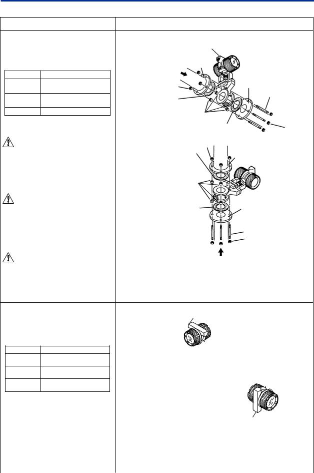
|
|
|
<3. INSTALLATION> |
3-8 |
|
Table 3.3 (a) Installation of Wafer Type Vortex Flowmeter |
|
|
|||
Wafer type |
|
Description |
|
||
When Installation Collar are required, the |
Horizontal Installation |
|
|
||
|
Electrical |
|
|
||
installation vortex flowmeters applied to the |
|
Connection |
|
|
|
following line sizes and flange ratings. |
|
|
|
|
|
|
|
|
Flange |
|
|
|
Flange Rating |
|
Flow |
|
|
Size mm (inch) |
|
Direction |
|
|
|
15 to 40 |
All ratings |
|
Nut |
Flange |
|
(1/2 to 1-1/2) |
|
|
|||
|
|
|
Bolt (4 pcs.) |
|
|
|
JIS 10K, ANSI class 150, |
|
Gasket |
|
|
50(2) |
|
|
|
||
DIN PN10 to PN40 |
|
|
|
|
|
|
|
|
|
|
|
80(3) |
ANSI class 150 |
|
Collar (4 pcs.) |
|
|
|
|
|
|
|
|
|
|
|
Gasket |
Nut |
|
WARNING |
Vertical Installation |
|
|
||
|
Nut |
|
|
||
The inside diameter of the gasket must |
|
Gasket |
Flange |
|
|
|
|
|
|||
be larger than the pipe inner diameter |
|
|
|
||
|
|
|
|
||
so that it will not disturb the flow in the |
|
|
|
|
|
pipeline. |
|
|
|
|
|
|
|
|
Collar (4 pcs.) |
|
|
|
|
|
|
Electrical |
|
WARNING |
|
|
Connection |
|
|
|
Gasket |
|
|
||
When installing the Flowmeter vertically in the |
|
Flange |
|
||
open air, change the electrical connection port |
|
|
|
|
|
direction to the ground. If the electrical |
|
|
|
|
|
connection port is installed upwards, rain |
|
|
Bolt (4 pcs.) |
|
|
water might leak in. |
|
|
|
||
|
|
Nut |
|
||
|
|
|
|
|
|
WARNING |
|
Flow Direction |
|
||
|
|
|
|
||
In case of vertical installation, two collars in |
(1) Insert two collars on each two bolts of bottom side of the flowmeter. |
|
|||
the upper part might move after the |
(2) Fit the flowmeter body to the collars. And tighten the four bolts and nuts |
||||
installation. But it doesn't influence the |
|
uniformly. |
|
|
|
performance, please use the flowmeter under |
(3) Check for leakage from the flange connections. |
|
|||
such condition. |
|
|
|
|
|
When Installation Collars are not required,the |
Horizontal Installation |
Vertical Installation |
|||
Flow |
Electrical Connection |
|
|||
installation vortex flowmeters applied to the |
Direction |
|
|
||
following line sizes and flanges. |
|
|
|
|
|
Size mm (inch) |
Flange Rating |
Nut |
Bolt Hole |
|
|
|
Flange |
|
|||
|
JIS 20K, 40K |
|
|
||
50(2) |
|
|
|
|
|
ANSI class 300,600 |
Stud Bolt (8 pcs.) |
|
|
||
|
|
|
|||
|
JIS 10K, 20K, 40K |
|
|
||
80(3) |
|
Flange |
|
|
|
ANSI class 300, 600 |
|
|
|
||
|
|
Gasket |
|
|
|
100(4) |
JIS 10K, 20, 40K |
|
|
|
|
|
|
|
|
||
ANSI class 150, 300, 600 |
|
|
|
|
|
|
|
|
|
|
|
|
|
|
Gasket |
|
|
|
|
|
Nut |
|
|
|
|
(1) Insert two stud bolts in the bolt holes |
Electrical |
|
|
|
|
Connection |
|
||
|
|
|
on the flowmeter shoulder to align |
|
|
|
|
|
the instrument body with the inner |
|
|
|
|
|
diameter of the adjacent piping. |
|
|
(2)Tighten all bolts uniformly and check that there is no leakage between the
instrument and the flanges. |
Flow |
|
|
|
Direction |
||||
|
|
|
|
|
|
|
F0312.ai |
||
|
|
|
|
|
IM 01F06A00-01EN
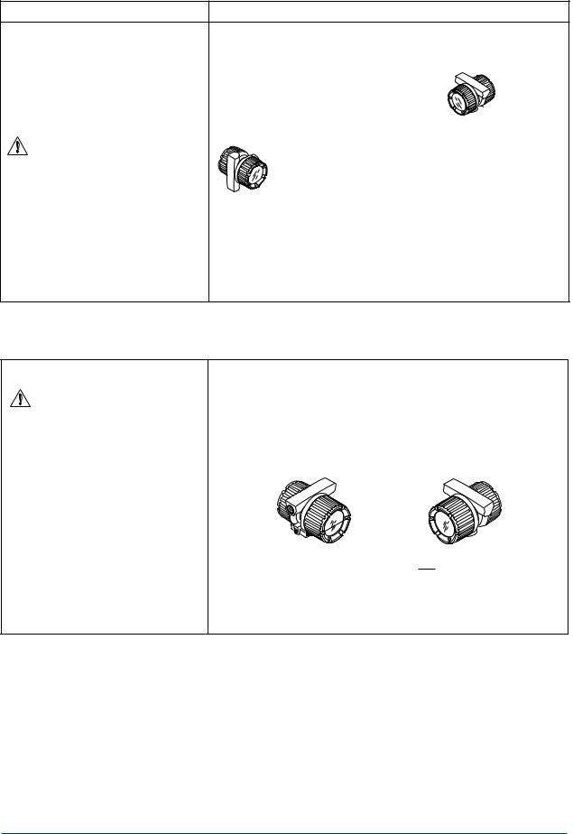
<3. INSTALLATION> |
3-9 |
Table 3.3 (b) Installation of Flange Type Vortex Flowmeter
Flange type |
Description |
Use the stud bolts and nuts supplied with the
flowmeter of the user. Horizontal Installation
The gaskets should be supplied by the user.
|
Flow Direction |
|
|
|
Flange |
CAUTION |
Nut |
Flange |
Stud Bolt |
|
|
The inside diameter of the gasket must be |
|
Gasket |
larger than the pipe inner diameter so that it |
|
Nut |
will not disturb the flow in the pipeline. |
|
|
|
|
|
|
|
Gasket |
Flow Direction
Vertical Installation
F0313.ai
Table 3.3 (c) Installation of Remote Type Converter
Remote type converter |
|
|
Description |
|
CAUTION |
The converter is mounted on a 2-inch (60.5mm outer dia.) stanchion or horizontal |
|||
A signal cable (DYC) is used between the |
pipe. |
|
|
|
Do not mount the converter on a vertical pipe. It makes wiring and maintenance |
||||
remote type flowmeter and the converter. |
difficult. |
|
|
|
The maximum signal cable length is 97.5ft |
The converter mounting orientation can be changed as illustrated below. |
|||
(30m). |
Stanchion |
|
|
Mounting |
|
Mounting |
Horizontal Pipe |
||
Nut
Bracket
2-inch Pipe
U-Bolt
F0314.ai
IM 01F06A00-01EN

<4. WIRING> |
4-1 |
4.WIRING
 WARNING
The wiring of the vortex flowmeter must be performed by expert engineer or skilled
personnel. No operator shall be permitted to perform procedures relating to wiring.
 CAUTION
Once all wiring is complete, check the connections before applying power to the instrument. Improper arrangements or wiring may cause a unit malfunction or damage.
4.1Load Resistance of Output Condition
Be sure to observe the following precautions when wiring:
 CAUTION
•In cases where the ambient temperature exceeds +50°C (+122°F), use external heatresistant wiring with a maximum allowable temperature of +70°C (+158°F) or above.
•Do not connect cables outdoors in wet weather in order to prevent damage from condensation and to protect the insulation.
•Do not splice the cable between the flowtube terminal and the converter if it is too short. Replace the short cable with a cable that is the appropriate length.
•All the cable ends must be provided with round crimp-on terminals and be securely wired.
•Be sure to turn power off before opening the cover.
•Before turning the power on, tighten the cover securely.
•Explosion protected types must be wired in accordance with specific requirement (and, in certain countries, legal regulations) in order to preserve the effectiveness of their explosion protected features.
•The terminal box cover is locked by the Locking Screw. In case of opening the terminal box cover, use the hexagonal wrench attached.
•Be sure to lock the cover by the Locking Screw using the hexagonal wrench attached after installing the cover.
Table 4.1 shows the connection method of several output conditions.
(1)Analog Output (4 to 20 mA DC)
This converter uses the same two wires for both, the signal and power supply. A DC power supply is required in a transmission loop.
The total leadwire resistance including the instrument load and power distributor (supplied by the user) must conform to a value in the permissible load resistance range. Refer to Figure 4.1.
IM 01F06A00-01EN
<4. WIRING> |
4-2 |
|
600 |
|
|
|
|
) |
E–10.5 |
Communication |
|
||
( |
R= 0.0236 |
|
|||
Applicable range |
|
||||
R |
|
|
BRAIN and HART |
|
|
resistance |
|
|
|
||
250 |
|
|
|
|
|
Load |
|
|
|
|
|
|
10.5 |
16.4 |
24.7 |
30 |
42 |
Power Supply Voltage E (V)
F0401.ai
Figure 4.1 Relationship between Power Supply Voltage and Load Resistance (4 to 20 mA DC Output)
(2)Pulse output and Alarm, Status Output
This version uses three wires between the converter and the power supply. A DC power and load resistance are required, and pulse output is connected to a totalizer or an electric counter. Low level of the pulse output is 0
to 2V. No communication is possible over a transmission line. Communication via the
amplifier board is always possible irrespective of the wiring condition.
(3)Simultaneous Analog-Pulse Output
When using digitalYEWFLO in the simultaneous analog -pulse output mode, the communicable distance of the transmission line is restricted on the wiring method. Table 4.1 shows the examples of connection for this output mode. Communication via the amplifier board is always possible irrespective of the wiring condition.
 IMPORTANT
For pulse output and the simultaneous analogpulse output ,use the load resistance. Refer to Table 4.1.
4.2Selection of Wires
The following should be taken into consideration when selecting cables for use between the converter and distributor.
(1)Use 600V PVC insulated wire or equivalent standard wire or cable.
(2)Use shielded wire in areas susceptible to electrical noise (both analog and pulse output versions).
(3)In areas with high or low ambient temperatures, use wires or cables suitable for such temperatures.
(4)In atmospheres where oils or solvents, corrosive gases or liquids may be present, use suitable wires or cables.
(5)Use cable which withstand temperature up to +60°C and more, when ambient temperature is more than +60°C.
 IMPORTANT
For the remote type, use DYC signal cable to connect the converter and remote type flowmeter(DY-N).
4.3Connection
Table 4.1 shows the connection sample of connection for power supply and load resistance. The terminal position of each connection is shown in Figure 4.2.
Integral type |
Remote type |
||
|
|
|
|
|
Supply |
4 to 20 mA DC Output Power Supply |
|
|
+ |
and Output Signal Terminals |
|
|
– |
||
|
Pulse |
Pulse Output Terminal |
|
|
+ |
|
|
|
|
|
Grounding Terminal |
|
|
|
|
|
|
|
|
|
|
|
|
|
|
|
F0402.ai |
Figure 4.2 Terminal Position
IM 01F06A00-01EN
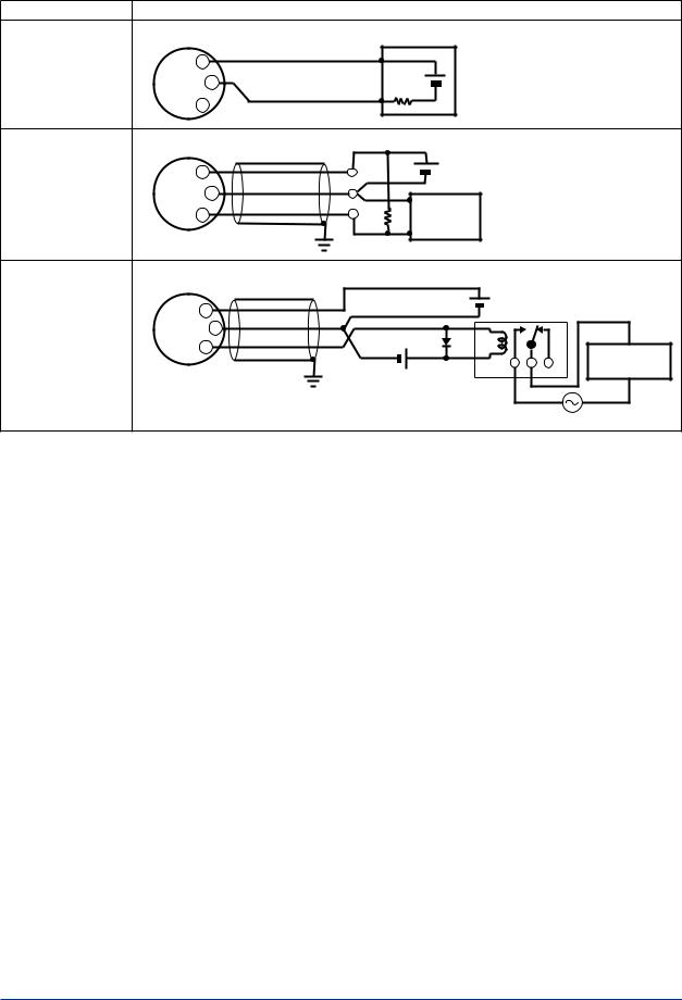
<4. WIRING> |
4-3 |
Table 4.1 (a) The wiring example for the analog and pulse and status, alarm output.
Connection |
|
Description |
|
|
Analog Output |
digitalYEWFLO Electrical Terminal |
|
Distributor |
|
|
|
+ |
|
|
In this case, Communication |
SUPPLY + |
24V DC |
|
|
is possible (up to a distance |
|
|
|
|
of 2km when a CEV cable is |
– |
|
|
|
used.) |
– |
250Ω |
|
|
PULSE + |
|
|||
|
|
|
|
|
Pulse Output |
digitalYEWFLO Electrical Terminal |
|
|
Use the Three-wire shielded cable. |
In this case, No |
Shielded Cable |
|
|
|
SUPPLY + |
|
E |
This supply voltage requires |
|
communication is possible. |
|
|||
|
|
a power sourse with a |
||
|
– |
|
|
maximum output current of |
|
PULSE + |
*2 R |
*1 |
no less than E/R+25mA. |
|
Electric counter |
|
||
Status Output |
digitalYEWFLO Electrical Terminal |
|
|
Use the Three-wire shielded cable. |
Alarm Output |
|
|
|
|
Shielded Cable |
|
|
|
|
|
|
E |
|
|
In this case, |
SUPPLY + |
|
Relay |
|
|
|
|||
No communication is |
|
|
||
– |
|
|
|
|
possible. |
|
|
|
|
|
PULSE + |
|
|
Magnetic |
|
|
|
|
|
|
|
External Power supply |
valve |
|
|
|
|
||
|
|
30V DC, 120mA max |
|
|
|
|
(Contact Rating) |
|
|
|
|
|
|
AC power supply |
*1: To avoid the influence of external noise, use an electric counter which fits to the pulse frequency.
*2: Resistor is not necessary in case of an electric counter which can receive contact pulse signal directly.
IM 01F06A00-01EN
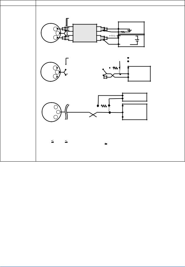
<4. WIRING> |
4-4 |
Table 4.1 (b) The wiring example for the simultaneous analog and pulse output, the calculation formula of the range of load registance R for the pulse output.
Connection |
|
|
|
Description |
|
|
Simultaneous |
When analog and pulse output are used, the length of communication line is subjected to wiring conditions. Refer to |
|||||
Analog |
example 1 to 3. If the communication carries out from amplifier, no need to consider wiring conditions. |
|||||
-Pulse Output *3 |
|
|
Shield |
|
Distributor (or communication medium) |
|
|
|
|
|
|||
Example 1 |
|
|
Shielded Cable |
|
|
For the shielded cables in this |
In this case, Communication |
|
+ |
|
|
24V DC |
example of flowmeter installation, |
is possible(up to a distance |
|
|
|
use two-wire separately |
||
of 2km when a CEV cable is |
SUPPLY |
|
|
250 |
shielded cables. *4 |
|
– |
Outer Jacket |
(R)*2 |
|
|||
used). |
|
E(10.5 to 30V DC) |
This supply voltage requires a |
|||
|
PULSE + |
|
|
|||
|
|
|
Counting input |
power sourse with a maximum |
||
|
|
|
|
|
|
output current of no less than |
|
digitalYEWFLO Electrical Terminal |
|
Common |
E/R. |
||
|
|
|
|
|||
|
|
|
|
Electric counter *1 (or communication medium) |
||
Example 2 |
|
|
|
|
|
|
|
|
|
Shield |
|
|
|
|
|
|
|
|
Recorder or |
|
|
For the shielded cables in this |
|||||||||||||||
In this case, Communication |
|
|
|
|
|
|
|
|
|
Shielded Cable |
|
|
|
|
|
|
|
|
other instrument |
|
|
example of flowmeter installation, |
|||||||||||||||
is possible (up to a distance |
|
|
|
|
|
|
|
|
|
|
|
|
|
|
|
|
|
|
|
use two-wire separately shielded |
|||||||||||||||||
of 200m when a CEV cable |
|
|
|
+ |
|
|
|
|
|
|
|
|
|
|
|
|
|
|
|
|
|
|
|
|
|
|
|
|
|
|
|
cables. *4 |
|||||
|
|
|
|
|
|
|
|
|
|
|
|
|
|
|
|
|
|
|
|
E(16.4 to 30V DC) |
|
|
|
|
|
This supply voltage requires a |
|||||||||||
is used) and R = 1kΩ). |
|
SUPPLY |
|
|
|
|
|
|
|
|
|
|
|
|
|
|
|
(R)*2 |
|
|
power sourse with a maximum |
||||||||||||||||
|
|
|
– |
|
Outer Jacket |
|
|
|
|
|
|
|
|
|
|
output current of no less than |
|||||||||||||||||||||
|
|
PULSE + |
|
|
|
|
|
|
|
|
|
|
|
|
|
|
|
|
|
Counting input |
|
|
|
|
E/R+25mA. |
||||||||||||
|
|
|
|
|
|
|
|
|
|
|
|
|
|
|
|
|
|
Common |
|
|
|
|
|
|
|
|
|
|
|
|
The supply voltage requires output |
||||||
|
|
|
|
|
|
|
|
|
|
|
|
|
|
|
|
|
|
|
|
|
|
|
|
|
|
|
|
|
|||||||||
|
|
|
|
|
|
|
|
|
|
|
|
|
|
|
|
|
|
|
|
|
|
|
|
|
|
|
|
|
|
|
|
|
|
|
|
|
impedance no more than 1/1000 |
|
|
|
|
|
|
|
|
|
|
|
|
|
|
|
|
|
|
|
|
|
|
Electric counter *1 of R (load resistance). |
|||||||||||||||
|
digitalYEWFLO Electrical Terminal |
|
|
|
|
|
|
|
|||||||||||||||||||||||||||||
|
|
|
|
|
|
|
|
|
(or communication medium) |
||||||||||||||||||||||||||||
|
|
|
|
|
|
|
|
|
|
|
|
|
|
|
|
|
|
|
|
|
|
|
|||||||||||||||
Example 3 |
|
|
|
|
|
|
|
|
|
|
|
|
|
|
|
|
|
|
|
|
|
Recorder or |
|
|
|
||||||||||||
In this case, No communi |
|
|
|
|
|
|
|
|
|
|
|
|
|
|
|
|
|
|
|
|
|
|
|
|
|||||||||||||
|
|
|
|
|
|
|
|
|
|
|
|
|
|
|
|
|
|
|
|
|
other instrument |
|
|
|
|||||||||||||
-cation is possible (when |
|
|
|
|
|
|
|
|
|
|
|
|
|
|
|
|
|
|
|
|
|
|
|
|
|||||||||||||
|
|
|
|
|
|
|
|
|
|
|
|
|
|
|
|
|
|
|
|
|
|
|
|
|
|
|
|
|
|
|
|
|
|
|
|||
shielded cable is not used). |
|
|
|
|
|
|
|
|
|
|
|
|
|
|
|
|
|
|
E(16.4 to 30V DC) |
|
|
|
|
|
|
|
|
|
This supply voltage requires |
||||||||
|
|
|
|
|
|
|
|
|
|
|
|
|
|
|
|
|
|
|
|
|
|
|
|
|
|
|
|
||||||||||
|
|
SUPPLY + |
|
|
|
|
|
|
|
|
(R)*2 |
|
|||||||||||||||||||||||||
|
|
|
|
|
|
|
|
|
|
|
|
|
|
|
|
|
|
|
|
|
|
|
|
a power sourse with a |
|||||||||||||
|
|
|
|
|
– |
|
|
|
|
|
|
|
|
|
|
|
|
|
|
|
|
|
|
|
|
|
|
|
|
|
maximum output current of |
||||||
|
|
|
|
|
|
|
|
|
|
|
|
|
|
|
|
|
Counting input |
|
|
|
|
|
|
|
|||||||||||||
|
|
|
|
|
|
|
|
|
|
|
|
|
|
|
|
|
|
|
|
|
|
|
|
no less than E/R+25mA. |
|||||||||||||
|
|
PULSE + |
|
|
|
|
|
|
|
|
|
|
|
|
|
|
|
Common |
|
|
|
|
|
|
|
|
|
|
|
||||||||
|
|
|
|
|
|
|
|
|
|
|
|
|
|
|
|
|
|
|
|
|
|
|
|
|
|
|
|||||||||||
|
|
|
|
|
|
|
|
|
|
|
|
|
|
|
|
|
|
|
|
|
|
|
|
|
|
||||||||||||
|
digitalYEWFLO Electrical Terminal |
|
|
|
|
|
|
|
Electric counter *1 |
|
|
|
|||||||||||||||||||||||||
|
|
|
|
|
|
|
|
(or communication medium) |
|||||||||||||||||||||||||||||
|
|
|
|
|
|
|
|
|
|
|
|
|
|
|
|
|
|
|
|
|
|
|
|
|
|
|
|
|
|
|
|
|
|
|
|
||
The range of load |
The load resistance should be selected by calculation as shown below. |
|
|
|
|||||||||||||||||||||||||||||||||
resistance R for the |
|
E (V) |
|
|
|
|
|
|
|
0.1 |
|
|
|
|
|
|
|
|
|
|
|
|
|
|
|
|
|
|
|
|
|
|
|
|
|
|
|
pulse output. |
|
R (k ) |
|
|
|
|
Example of CEV cable capacitance |
|
|
|
|||||||||||||||||||||||||||
|
120 |
|
|
|
|
|
|
|
C ( μF ) × f ( kHz ) |
|
|
0.1μF/km |
|
|
|
|
|
|
|
|
|
|
|
|
|
|
|
|
|
||||||||
|
|
|
|
|
E2 (V) |
|
Where |
|
|
|
|
|
|
|
C = Cable capacitance (μF) |
||||||||||||||||||||||
|
|
|
|
|
|
|
|
|
|
|
E = Supply voltage (V) |
|
|||||||||||||||||||||||||
|
P (mW) = R (k ) |
|
f = Frequency of pulse output (kHz) |
|
P = Power ratio of the load resistance |
||||||||||||||||||||||||||||||||
|
|
|
|
|
|
|
|
|
|
|
R = Value of load resistance (k ) |
|
|
(mW) |
|
|
|
||||||||||||||||||||
*1: To avoid the influence of external noise, use an electric counter which fits to the pulse frequency.
*2: Resistor is not necessary in case of an electric counter which can receive contact pulse signal directly.
*3: When using analog and pulse output simultaneously, the HART communication may be influenced by noise comparing analog output only.
*4: Signal Cable for ADMAG AXF, AXFC-0 (No Termination) is available.
IM 01F06A00-01EN
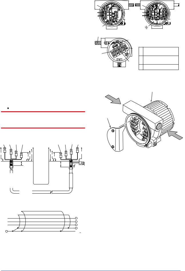
<4. WIRING> |
4-5 |
4.4Connection of DYC Signal Cable
The remote type signal cable is shown in Figure 4.3 and Figure 4.4, and the terminal is shown in Figure 4.5.
The maximum cable length is 30 m (97.5 feet). Remove terminal box cover and wiring connection dust-cap before wiring.
For remote type the converter has two electrical connections (cable inlets). Use the left connection as viewed from the terminal box for the DYC signal cable and the right connection for the transmission cable.
If a signal cable kit is supplied by YOKOGAWA, both ends of the cable must be finished in accordance with the following instructions. Refer to Section 4.5 “End Processing Method of DYC Signal Cable“.
T |
A |
B |
C |
Flowmeter(DY-N)
DYC
T |
A |
B |
C 


Converter(DYA)
|
C |
T: Only for /MV |
|
|
|
B |
Input Terminal from built- |
|
|
T |
|
T |
|
in temperature sensor |
|
|
|
A |
Input Terminals from |
|
A |
B |
vortex detector |
Detector (DY-N.../E1) |
C |
Common Terminal |
|
|
|
||
|
|
|
F0405.ai |
Figure 4.5 |
Terminal of Detector and Converter |
||
Signal Cable(DYC) |
Vortex Flow Converter |
|
 CAUTION
After completing the signal cable connections, install the shielded cover to signal cable terminal as shown in Figure 4.6.
Unit : mm
C |
B |
A |
T |
|
|
T |
A |
|
B |
C |
||||||
(Black) (White) |
(Red) |
(Yellow) |
|
|
(Yellow) |
(Red) |
(White) |
(Black) |
||||||||
|
|
|
|
|
|
|
|
|
|
|
|
|
|
|
|
|
|
|
|
|
|
|
|
|
|
|
|
|
|
|
|
|
|
|
|
|
|
|
|
|
|
|
|
|
|
|
|
|
|
|
80 |
70 |
70 |
80 |
|
60 |
60 |
|
|
50 |
50 |
|
20 |
25 |
95 (Blue) |
|
||
|
|
Flowmeter |
|
|
Specified |
|
|
|
|
|
|
|
Length (L) |
|
|
|
30m (max.) |
|
|
|
|
|
|
DYC |
|
|
|
T: Only for / MV |
|
Figure 4.3 DYC Signal Cable
Outer shield
To Flowmeter
(Yellow) T 
(Red) A
(White) B
(Black) C |
Inner shield |
|
|
|
T: Only for / MV |
Converter
F0403.ai
To Converter
T (Yellow)
A (Red)
B (White)
C (Black)

 (Bule)
F0404.ai
Figure 4.4 Construction of DYC Signal Cable
Shield Cover
Power Cable
F0406.ai
Figure 4.6 Shielded Cover
IM 01F06A00-01EN
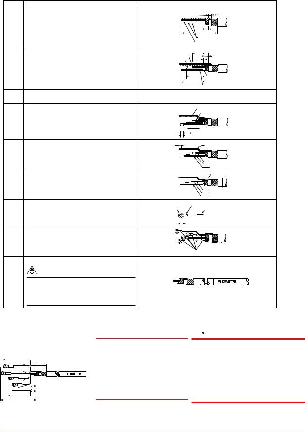
<4. WIRING> |
4-6 |
4.5End Processing Method of DYC Signal Cable
4.5.1 For Vortex Flowmeter (DY-N) |
|
|
|
|
|
|
Description |
|
|
Figure |
|
1 |
Strip off the outer polyethylene jacket, outer braided |
|
|
5 (0.2) 10 (0.4) |
Unit : mm |
|
shield and inner jacket, and inner braided shield as |
|
|
|
(approx. inches) |
|
per the dimensions below. |
|
|
5 (0.2) |
|
|
|
|
|
|
|
|
|
|
|
90 (3.5) |
|
|
|
|
|
Conductive Layer (Black) |
|
|
|
|
|
T*1 (Yellow) |
|
2 |
Strip off the black conductive layer convering two |
T*1 |
(Yellow) |
40 (1.6)5 (0.2) |
|
|
wires completely, as per the dimensions below. |
3 (0.1) |
|
||
|
A (Red) |
or less |
|
||
|
Twist each of the conductor and drain wires so that |
|
|
||
|
|
|
|
|
|
|
there are no free strands. |
|
|
|
|
50 (2.0) |
Conductive Layer (Black) |
60 (2.4)
B (White)
3Do not short-circuit the conductive layer and the terminals (A, B, C and T*1).
4 |
Strip off about 5 mm (0.2 in.) of insulation for each |
Drain wires |
||
|
of wires A, B, and T*1, and twist the strands of each |
C (Black) |
T*1 (Yellow) |
|
|
wire. Twist the inner and outer drain wires together. |
A (Red) |
|
|
|
|
B (White) |
|
5 (0.2) |
|
|
5 (0.2) |
5 (0.2) |
|
|
|
|
|
|
5 |
Slide FEP (fluorinated ethylene propylene) tubing |
5 (0.2) |
|
FEP Insulation Tubing |
|
over the twisted inner and outer drain wires C until |
C (Black) |
|
(Black) |
|
the tubing cannot be slid any further, and then cut |
|
|
|
|
off the tubing leaving 5 mm (0.2 in.) of the stranded |
|
|
T*1 (Yellow) |
|
drain wires exposed. |
|
|
A (Red) |
|
|
|
|
B (White) |
6 |
Slide heat shrinkable tubing over the cable end so |
C(Black) |
Heat Shrinkable Tubing |
|
|
that the tubing covers the braided shield and |
|
|
|
|
overlaps both the polyethylene jacket and loose |
|
|
T*1 (Yellow) |
|
1 |
|
|
|
|
wires A, B, C, and T* . |
|
|
A (Red) |
|
|
|
|
B (White) |
7 |
Slide a short piece of heat shrinkable tubing over |
Lug tip |
|
|
|
Crimp and Solder Here |
||||||||
|
each of wires A, B, C, and T*1. Install a crimp-on |
|
|
|
|
|
|
|
Heat Shrinkable Tubing |
|||||
|
|
|
|
|
|
|
|
|
||||||
|
terminal lug at the tip of each wire. Crimp and |
|
|
|
|
|
|
|
|
|
|
|
|
|
|
solder each lug. |
|
10 |
|
|
|
|
|
|
|
|
|
|
|
|
|
|
|
|
|
|
|
|
|
|
|
|
|
|
8 Slide each short piece of heat shrinkable tubing over the crimp sleeve. Heat all pieces of heat shrinkable tubing with a heat blower or dryer.
Heat Shrinkable Tubing
9 Attach an identification label to the end of the cable.
NOTE
Check that the insulation resistance between each wire including the inner shield is 10M or greater at 500V DC. Ensure that both ends of the wires are disconnected (open-circuited) during the check.
(*1): Only for /MV
80 (3.15) |
|
Unit : mm |
|
Black |
(C) |
20 (0.79) |
(approx. inches) |
|
|||
White |
(B) |
|
|
Red |
(A) |
|
|
Yellow*1(T) 50 (1.97) |
|
|
|
60 (2.36) |
|
|
|
70 (2.76) |
|
F0408.ai |
|
|
|
|
|
 NOTE
NOTE
In case that the cable end finish parts assembly is necessary after delivery, contact your nearest Yokogawa sales office or the sales representative from which you purchased the product.
F0407.ai
 CAUTION
Do not touch the '' conductive layer" (black area covering the signal cables A and B) to the converter case, terminal, and other leadwires. If it is touched, operation of the converter may be incorrect. When the cable is terminated, remove the conductive layer properly.
Figure 4.7 End Processing Method of DYC Signal Cable for Detector
IM 01F06A00-01EN
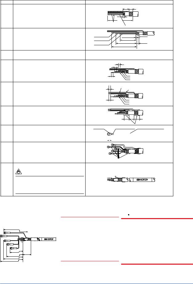
<4. WIRING> |
4-7 |
4.5.2 For Vortex Flow Converter (DYA) |
|
|
|
|
|
Description |
|
Figure |
|
1 |
Strip off the outer polyethylene jacket, outer braided |
15 (0.6) 10 (0.4) |
Unit : mm |
|
|
shield and inner jacket, and inner braided shield as |
|
|
(approx. inches) |
|
per the dimensions as shown. |
|
|
|
|
|
95 |
5 (0.2) |
|
|
|
(3.7) |
|
|
Conductive |
T*1 (Yellow) |
Layer (Black) |
2 |
Cut of the black conductive layers(convering the |
|
|
|
|
|
|
two wires) completely, as per the dimensions below. |
B (White) |
|
3 (0.1) or less |
|
Conductive |
|
Twist each of the conductor and drain wires so that |
|
|
|||
|
A (Red) |
|
40 (1.6) |
|
||
|
there are no free strands. |
|
5 (0.2) |
Layer (Black) |
||
|
T*1 (Yellow) |
|
50 (2.0) |
|||
|
|
|
|
|
||
|
|
|
|
60 (2.4) |
|
|
3 |
Do not short-circuit the conductive layer and the |
|
|
|
|
|
|
terminals (A, B, C, G, and T*1). |
|
|
|
|
|
4 |
Strip off about 5 mm (0.2 in.) of insulation for each |
|
5 (0.2) |
|
|
|
|
of wires A, B, and T*1, and twist the strands of each |
G 5 (0.2) |
Drain wires |
|
|
|
|
wire. |
C |
|
|
|
|
|
|
|
5 (0.2) |
T*1 (Yellow) |
|
|
|
|
|
A (Red) |
|
|
|
|
|
|
|
B (White) |
|
|
5 |
Slide black FEP (fluorinated ethylene propylene) |
|
5 (0.2) |
FEP Insulation Tubing (Black) |
||
|
tubing over the inner shield drain wire C and blue |
|
|
|||
|
|
|
FEP Insulation Tubing (Blue) |
|||
|
FEP tubing over outer shield drain wire G until |
G |
|
|||
|
|
|
|
|
||
|
the tubing cannot be slid any further, and then cut |
C (Black) |
|
|
|
|
|
off the tubing leaving 5 mm (0.2 in.) of the drain |
|
5 (0.2) |
T*1 (Yellow) |
|
|
|
wires exposed. |
|
A (Red) |
|
|
|
|
|
|
|
B (White) |
|
|
6 |
Slide heat shrinkable tubing over the cable end so |
G |
|
|
|
|
|
that the tubing covers the braided shield and |
C (Black) |
A (Red)T |
|
|
|
|
overlaps both the polyethylene jacket and loose |
B (White) |
|
|
|
|
|
|
15 (0.6) |
25 (1.0) |
|
||
|
wires A, B, C, G, and T*1. |
|
|
|||
|
|
|
|
|
|
|
|
|
|
|
Heat Shrinkable Tubing |
||
7 |
Slide a short piece of heat shrinkable tubing over |
Lug-Tips |
|
|
|
Crimp and Solder Heat-shrinkable tubing |
|||||
|
each of wires A, B, C, G, and T*1. Install a crimp-on |
|
|
|
|
|
|
|
|
|
|
|
terminal lug at the tip of each wire. Crimp and |
|
10 |
|
|
|
|
|
|
|
|
|
solder each lug. |
|
|
|
|
|
|
|
|
|
|
|
|
(0.4) |
|
|
|
|
|
|
|
|
|
|
|
|
|
|
|
|
|
|
|
|
|
8 Slide each short piece of heat
shrinkable tubing over the crimp sleeve. Heat all pieces of heat shrinkable tubing with a heat blower or dryer.
Heat Shrinkable Tubing
9 Attach an identification label to the end of the cable.
NOTE
Check that the insulation resistance between each wire including the inner shield is 10M or greater at 500V DC. Ensure that both ends of the wires are disconnected (open-circuited) during the check.
(*1): Only for /MV
|
95 (3.74) |
||
Blue |
(G) |
|
|
Black |
(C) |
|
|
White |
(B) |
|
|
Red (A) |
3 |
||
|
|
MAX |
|
Yellow*1(T) 50 (1.97) |
|||
60 (2.36) |
25 (0.98) |
||
70 (2.76) |
|||
|
|||
80 (3.15) |
|
||
Unit : mm (approx. inches)
F0410.ai
 NOTE
NOTE
In case that the cable end finish parts assembly is necessary after delivery, contact your nearest Yokogawa sales office or the sales representative from which you purchased the product.
F0409.ai
 CAUTION
Do not touch the '' conductive layer" (black area covering the signal cables A and B) to the converter case, terminal, and other leadwires. If it is touched, operation of the converter may be incorrect. When the cable is terminated, remove the conductive layer properly.
Figure 4.8 End Processing Method of DYC Signal Cable for Converter
IM 01F06A00-01EN
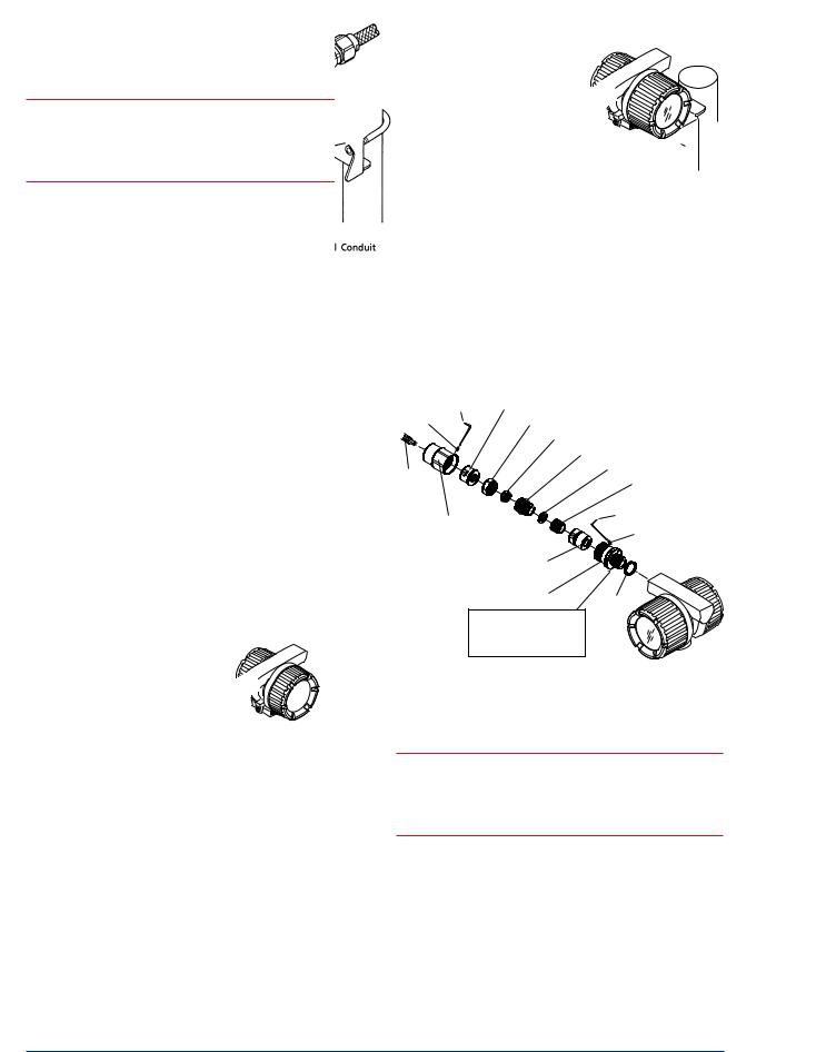
<4. WIRING> |
4-8 |
4.6Wiring Procedures and Precautions
 NOTE
NOTE
Once all wiring is complete, check the connections before applying power to the instrument. Improper arrangements or wiring may cause a unit malfunction or damage.
(1)Lay wiring as far as possible from electrical noise sources such as large capacity transformers, motors, and power supplies.
(2)Remove the terminal cover and dustproof plug of an electrical connection before wiring. When you open the cover of explosion proof type(*), turn the Locking Screw to the right, and unlock When you close a cover after wiring, be sure turn the Locking Screw to the left and lock.
(*)Flameproof(TIIS,ATEX,IECEx), Intrinsically safe(SAA)
(3)It recommends using an flexible metal conduit and a duct for waterproofing or external protection of an electric wire. Refer to Figure 4.9 and Figure 4.10.
(4)The flameproof packing adapter (option code: /G11 or /G12) should be used for the external wiring of TIIS Flameproof. Refer to “INSTALLATION AND OPERATING PRECAUTIONS FOR TIIS FLAMEPROOF EQUIPMENT.”
Terminal Box
Steel Conduit
Flameproof
Converter
Tee
Flexible Metal Conduit
Drain Fitting 
F0411.ai
Figure 4.9 Example of Wiring (Integral Type and
Remote Type Detector)
Terminal Box
Steel Conduit for
Flameproof
Converter
Flexible Metal Conduit
Tee
Drain Fitting
F0412.ai
Figure 4.10 Example of Wiring (Remote Type
Converter)
Wrench |
B. Coupling |
|
Lock Nut |
Clamp Nut |
|
|
Clamp Ring |
|
|
Packing Gland |
|
|
Washer |
|
Cable |
Packing |
|
|
||
Union Nut |
Wrench |
|
Lock Nut |
||
|
||
|
Packing Case |
|
|
Adapter Body |
|
|
O-Ring |
Apply a nonhardnening sealant to the threads for watweproofing
F0413.ai
Figure 4.11 Cable Wiring
 NOTE
NOTE
Be sure to use the flameproof packing adapter (option code:/G11 or /G12) for TIIS flameproof type at the time of cable wiring work. Refer to Table 4.2.
Table 4.2 Flameproof packing adaptor
|
Diameter for |
Cable outer |
Identification |
|
||
Option Code |
diameter |
Parts NO. |
||||
screw |
mark |
|||||
|
mm (inch) |
|
||||
|
|
|
|
|
||
G11 |
G11 |
ø8.0 to ø10.0 |
16 |
8-10 |
|
|
(ø0.31 to ø0.39) |
|
|||||
|
|
|
|
G9601AM |
||
|
|
ø10.0 to ø12.0 |
|
|
||
G12 |
G12 |
16 10-12 |
|
|||
(ø0.39 to ø0.47) |
|
|||||
|
|
|
|
|
||
IM 01F06A00-01EN
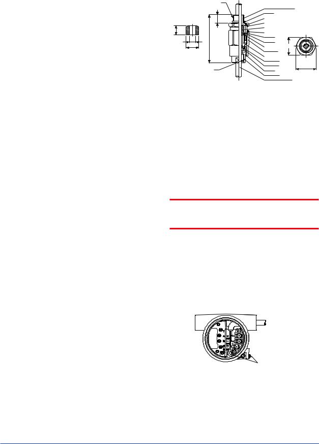
<4. WIRING> |
4-9 |
(5)Perform attachment of flameproof packing adaptor in the following ways. Refer to Figure 4.11.
(a)Loosen the locking screw and remove the terminal box cover.
(b)Measure the cable outer diameter in two directions to within 0.1 mm.
(c)Calculate the average of the two diameters, and use packing with an internal diameter nearest to this value. Refer to Table 4.2.
(d)Screw the flameproof packing adapter into the terminal box until the O-Ring touches the wiring port (at least 6 full turns), and firmly tighten the lock nut.
(e)Insert the cable through the union nut, the B. coupling, the clamp nut, the clamp ring, the packing gland, the washer, the packing, and the packing case, in that order.
(f)Insert the end of the cable into the terminal box.
(g)Tighten the union cover to grip the cable. When tightening the union cover, tighten approximately one turn past the point where the cable will no longer move up and down. Proper tightening is important. If it is too tight, a circuit break in the cable may
occur; if not tight enough, the flameproof effectiveness will be compromised.
(h)Fasten the cable by tightening the clamp nut.
(i)Tighten the lock nut on the union nut.
(j)Connect the cable wires to each terminal.
(6)
(a)Do not connect cables outdoors in wet weather in order to prevent damage from condensation and to protect the insulation.
(b)Do not splice the cable between the flowtube terminal and the converter if it is too short. Replace the short cable with a cable that is the appropriate length.
(c)The signal cables must be routed in separate steel conduit tubes 16 (JIS C 8305) or flexible conduit tubes 15 (JIS C 8309).
(d)Always route the power and output signal cables in separate steel conduit tubes, except when the power supply voltage is 24 V and four-core cables are used for wiring. Keep conduits or flexible tubes watertight using sealing tape.
(7)For the TIIS flameproof type with wiring using a flameproof packing adapter, wire cables through the packing adapters approved by Yokogawa (option code: /G11 or /G12).
|
T1 |
|
16.5 |
18 |
|
F |
L |
G |
|
*Packing |
|
(Choose from the table |
|
below depend on cable |
|
outside diameter) |
T2 |
Adapter body (M. Screw)
O-Ring
Packing case |
Unit : mm |
(approx. inch) |
|
Hexagon socket set screw |
|
Packing * |
|
Hexagon socket set screw |
|
O-Ring |
|
O-Ring |
|
Washer |
C |
|
Union nut |
|
|
Packing gland |
|
|
Clamp ring |
|
|
Clamp nut |
D |
|
O-Ring |
||
|
||
B.coupling |
|
|
Cable (user’s scope) |
||
|
|
|
|
|
|
|
|
|
|
F0414.ai |
|
|
|
|
|
|
|
|
|
|
|
|
|
Size |
|
|
Cable outer |
Packing |
Identification |
Weight |
||
|
|
|
|
dimensions |
||||||
|
|
|
|
|
||||||
|
|
|
|
|
diameter |
|
|
|
mark |
kg (lb) |
T1 |
T2 |
C |
D |
L |
|
F |
G |
|
|
|
|
|
|
|
|
|
|
|
|
|
|
|
|
|
|
|
ø8.0 to ø10.0 |
ø10.0 |
|
16 |
8-10 |
|
|
|
35 |
39 |
94.5 |
(ø0.31 to ø0.39) |
(ø0.39) |
ø20.0 |
0.26 |
||
G 1/2 |
G 1/2 |
|
|
|||||||
(1.38) |
(1.54) |
(3.72) |
ø10.0 to ø12.0 |
ø12.0 |
(ø0.79) |
16 |
10-12 |
(0.57) |
||
|
|
|
|
|
(ø0.39 to ø0.47) |
(ø0.47) |
|
|
||
|
|
|
|
|
|
|
|
|
||
|
|
|
|
|
|
|
|
|
|
|
Figure 4.12 Flameproof Packing Adapter (option
code: /G11, /G12)
4.7Grounding
 IMPORTANT
When a lightning protector (option code: /A) is selected, use a grounding resistance of 10Ω or less.
(1)The grounding terminals  are located on the inside and outside of the terminal area. Either terminal may be used.
(2)For pulse output version, ground the flowmeter. Also ground the shielded cable between the converter and the pulse receiver.
(3)Grounding should satisfy Class D requirements (ground resistance 100Ω or less).
(4)Use 600V PVC insulated wire for grounding.
|
|
|
Grounding |
|
|
|
|
Example: Integral Type |
Terminals |
||
|
|||
|
|
|
F0415.ai |
Figure 4.13 Grounding Terminal
IM 01F06A00-01EN

<5. BASIC OPERATING PROCEDURES> |
5-1 |
5.BASIC OPERATING PROCEDURES
Data setting can be performed with the three keys on the front panel (SET,SHIFT and INC) or using a handheld BRAIN TERMINAL (BT200) and HART communicator.
5.1Display Configuration
Figure 5.1 shows the configuration of the digitalYEWFLO display panel (if equipped).
4 Unit Display
3 Alarm Display
2Data Display
(Lower)
4 Unit Display
1 Data Display
(Upper)
SET
SHIFT INC
5 Setting Keys
F0501.ai
Figure 5.1 Display Configuration
1 |
Data Display(Upper) : flowrate data, setting data, |
|
|
|
total data |
|
|
temperature data (/MV) |
2 |
Data Display(Lower) : total data, alarm data |
|
|
|
temperature data (/MV) |
3 |
Alarm Display |
: alarm of a flow error and a |
|
|
vibration error |
4 |
Unit Display |
: flowrate unit |
5 |
Setting Keys |
: These keys are used to |
|
|
change flow rate data |
|
|
displays and type of |
|
|
setting data |
IM 01F06A00-01EN

<5. BASIC OPERATING PROCEDURES> |
5-2 |
5.2Display Contents
The display content items are classified in the following three items.
Table 5.1 Mode Name List
Mode (status) Name |
Display Contents |
Flow rate display mode |
A mode in which instantaneous flow rates or totalized values are displayed. |
|
Display content is usually selected either in display content selection mode or by setting |
|
parameters via BRAIN communication. |
Setting mode |
In this mode, parameter contents are confirmed or data is updated using the setting section. The |
|
mode is changed to this mode when “SET” key is pressed in normal mode. |
Alarm number display mode |
This mode is overlapped when an alarm is occurring in display mode. The alarm number |
|
presentation to indicate alarm contents (about 2 sec) and the normal data display (about 4 sec ) are |
|
repeated alternatively. |
Mode represents that the system is in a state where the relevant setting or display is possible.
●Display Example
SET
SHIFT + SET
Flowrate Display Mode
UPPER |
LOWER |
Flow rate |
Total rate |
|
|
|
|
UPPER |
LOWER |
Flow rate (%) |
Blank |
This mode display can be selected below.
Upper display : Flow rate
Lower display : Total rate or Blank
Setting Mode
Switching of setting number
SHIFT
This mode is used to check parameter content and rewrite data. This mode can be called up from the flowrate display mode by pressing the “SET” key.
Setting item and setting number can be changed when pressing “SHFT” key.
This mode can be called up by pressing “SET” key while pressing “SHIFT” key when setting mode is displayed.
Error Mode
NORMAL
INDICATION Alternately (4 sec)
ERROR INDICATION (2 sec)
When an alarm situation occurs, this mode will replace the current mode (flow rate or setting mode) to show what type of alarm has occurred.
Refer to Section 6.5 “SelfDiagnostic (Error Code List)” about the error descriptions and error number.
F0502.ai
IM 01F06A00-01EN
Loading...