


FieldMate
Table of contents
 Loading...
User’s
Manual
R2.05
R1.01
AXF
Verication Tool
IM 01R01A11-01EN
IM 01R01A11-01EN
1st Edition

Blank Page

AXF
Verication Tool
IM 01R01A11-01EN 1st Edition
CONTENTS
1 INTRODUCTION ........................................................................................ 1-1
1.1 About This Manual ............................................................................................1-2
1.2 Safety and Modication Precautions .............................................................1-2
1.3 Trademarks ........................................................................................................1-3
1.4 Software License Agreement ..........................................................................1-3
2 OUTILINE ................................................................................................... 2-1
2.1 Conguration .................................................................................................... 2-2
2.2 Verication Item ................................................................................................2-3
2.3 Operation Procedure ........................................................................................2-4
Toc-1
3 PREPARATION .......................................................................................... 3-1
3.1 Package and Installation ..................................................................................3-2
3.2 AXF Write Protect Cancellation .......................................................................3-2
3.2.1 Before Verication ..............................................................................3-2
3.2.2 During Verication ..............................................................................3-3
4 START-UP FROM FieldMate .................................................................... 4-1
4.1 From “Segment Viewer”
(AXF is reading in “online” mode in FieldMate) ............................................4-2
4.2 From “Device Navigator” .................................................................................4-4
4.3 From “Verication Data” in “Device Maintenance Info” ............................... 4-6
4.4 From “History” ..................................................................................................4-8
5 LAUNCHING .............................................................................................. 5-1
5.1 Creating New Verication Data ........................................................................5-2
5.2 Loading Existing Verication Data .................................................................5-4
5.3 After Unexpected Termination.........................................................................5-5
6 OPERATION .............................................................................................. 6-1
6.1 Main Screen ....................................................................................................... 6-2
6.1.1 Load ...................................................................................................6-3
6.1.2 Save ...................................................................................................6-4
6.1.3 Print out ..............................................................................................6-8
6.1.4 Menu bar ............................................................................................6-9
1st Edition’ Aug. 2012
All Rights Reserved, Copyright © 2012, Yokogawa Electric Corporation
IM 01R01A11-01EN

Toc-2
6.2 Standard VF ..................................................................................................... 6-11
6.2.1 “Circuit” check and “Device Status” check
(Verication Tool is in “online” mode) ...............................................6-12
6.2.2 Physical Appearance .......................................................................6-21
6.2.3 Standard VF Result ..........................................................................6-22
6.3 Enhanced VF ...................................................................................................6-23
6.3.1 Current Output ................................................................................6-25
6.3.2 Pulse Output ....................................................................................6-28
6.3.3 Converter .........................................................................................6-35
6.3.4 Insulation Resistance .......................................................................6-38
6.4 Result ...............................................................................................................6-39
7 VARIATION OF VERIFICATION DATA ..................................................... 7-1
7.1 Installation Data ................................................................................................7-1
7.2 Locked Data .......................................................................................................7-2
7.3 Others .................................................................................................................7-2
8 TERMINATION ........................................................................................... 8-1
8.1 Normal Termination ..........................................................................................8-1
8.1.1 When the verication data has not been changed after saving:........8-1
8.1.2 When the verication data has been changed after saving:..............8-1
8.2 Unexpected Termination ..................................................................................8-2
9 COMMUNICATION ERROR ...................................................................... 9-1
9.1 Error Message ...................................................................................................9-1
9.2 Device Address Setting ....................................................................................9-3
9.2.1 Multidrop Mode Canceling ................................................................ 9-3
9.2.2 Multidrop Mode Setting ......................................................................9-3
Revision Information ..............................................................................................1
IM 01R01A11-01EN
<1 INTRODUCTION>
1 INTRODUCTION
This User’s Manual gives instructions on “AXF Verication Tool”.
This software is used to set up magnetic owmeter AXF; therefore, it is indispensable for users
to read, understand and follow the instructions on all the following user’s manual before actually
starting the operation.
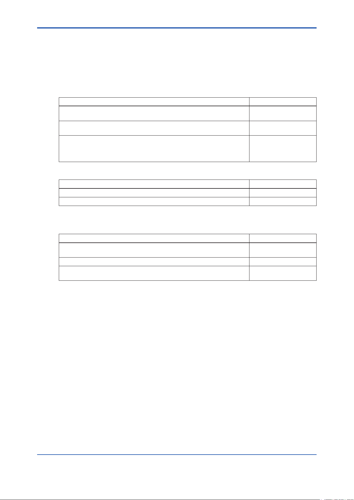
Table 1.1.1 User’s Manuals for magnetic owmeter ADMAG AXF
Title IM No.
AXF Magnetic Flowmeter, Integral Flowmeter/ Remote Flowtube
[Hardware Edition]
AXFA11G Magnetic Flowmeter, Remote Converter
[Hardware Edition/Software Edition]
AXFA14G/C Magnetic Flowmeter Remote Converter
[Hardware Edition/Software Edition]
AXF Magnetic Flowmeter Integral Flowmeter [Software Edition]
Table 1.1.2 User’s Manuals for external instruments
Title IM No.
Models AM012 Magnetic Flowmeter Calibrator FY2-XJAM012-40-2E
CA150 HANDY CAL IM CA150E
IM 01E20D01-01E
IM 01E20C01-01E
IM 01E20C02-01E
1-1
Refer to FieldMate User’s Manual when using AXF Verication Tool.
Table 1.1.3 User’s Manuals for FieldMate
Title IM No.
FieldMate
Versatile Device Management Wizard
FieldMate Operational Precaution IM 01R01A01-91E
FieldMate
Wizard Getting Started
IM 01R01A01-01E
IM 01R01A04-01E
IM 01R01A11-01EN
<1 INTRODUCTION>
1.1 About This Manual
• This manual should be provided to the end user.
• Before using the AXF Verication Tool, read this manual thoroughly to comprehend its contents.
• The contents of this manual may be changed without prior notice.
• All rights are reserved. No part of this manual may be reproduced in any form without
Yokogawa’s written permission.
• Yokogawa makes no warranty of any kind with regard to this material, including, but not
limited to, implied warranties of merchantability and suitability for a particular purpose.
• All reasonable effort has been made to ensure the accuracy of the contents of this manual.
However, if any errors or omissions are found, please inform Yokogawa.
• Yokogawa assumes no responsibilities for this product except as stated in the warranty.
• Please note that this user’s manual may not be revised for any changes in specications,
construction changes or operating part changes that are not considered to affect function or
performance.
• If the customer or any third party is harmed by the use of this product, Yokogawa assumes
no responsibility for any such harm owing to any defects in the product which were not predictable, or for any indirect damages.
1-2
• This manual describes the operation of the AXF Verication Tool with FieldMate Advance.
For detail installation and operation of FieldMate and additional functions, please refer to the
FieldMate User’s Manual.
1.2 Safety and Modication Precautions
• The following general safety precautions must be observed during all phases of operation, service, and repair of this instrument. Failure to comply with these precautions or with
specic WARNINGS given elsewhere in this manual violates safety standards of design,
manufacture, and intended use of the instrument. Yokogawa assumes no liability for the
customer’s failure to comply with these requirements. If this instrument is used in a manner
not specied in this manual, the protection provided by this instrument may be impaired.
• Yokogawa will not be liable for malfunctions or damage resulting from any modication
made to this instrument by the customer.
• The following safety symbols are used in this user’s manual and on the instrument.
WARNING
A WARNING sign denotes a hazard. It calls attention to a procedure, practice, condition or the
like, which, if not correctly performed or adhered to, could result in injury or death of personnel
CAUTION
A CAUTION sign denotes a hazard. It calls attention to a procedure, practice, condition or the
like, which, if not correctly performed or adhered to, could result in damage to or destruction of
part or all of the product.
IM 01R01A11-01EN

<1 INTRODUCTION>
IMPORTANT
An IMPORTANT sign denotes that attention is required to avoid damage to the instrument or
system failure.
NOTE
A NOTE sign denotes essential information for understanding operations and features.
1.3 Trademarks
All the brand names or product names of Yokogawa Electric used in this document are either
trademarks or registered trademarks of Yokogawa Electric Corporation.
All the brand names or product names of other companies mentioned in this document are either
trademarks or registered trademarks of their respective holders.
1-3
1.4 Software License Agreement
Refer to IM 01R01A01-01E Part A.
IM 01R01A11-01EN

Blank Page

<2 OUTILINE>
2 OUTILINE
AXF Verication Tool is a PC application software running in conjunction with FieldMate R2.05.00
or later.
Without having to remove the AXF magnetic owmeter from process line, its condition can be
veried by checking several items and this tool provides a certicate that the unit is operating in
accordance with YOKOGAWA standards. It is essentially an indication that the AXF is operating
to its standards and is useful in supporting plant maintenance practices. It differs from actual-ow
calibration at a manufacturing plant.
This tool stores verication data (*1) in a database (*2) in an organized manner, and can be used
to print a Verication Report that has not only the individual verication items (*3) result but also
the overall status of “passed” or “failed”. It is thus useful for device maintenance management.
*1: Verication data means the data saved by the user.
*2: Database means a collection of verication data saved in Device Maintenance Information.
*3: For the verication items, refer to 2.2.
2-1
IM 01R01A11-01EN
<2 OUTILINE>
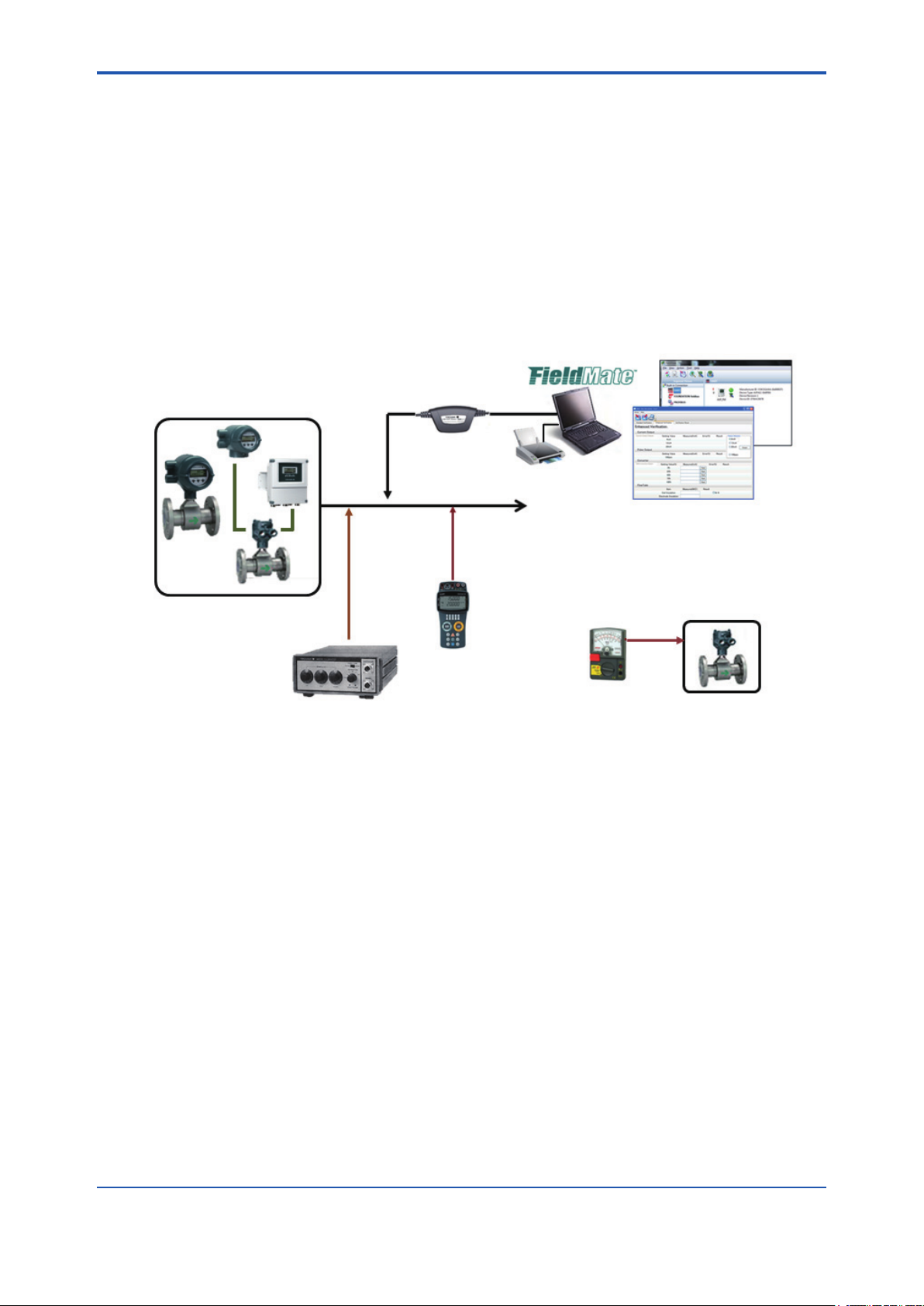
2.1 Conguration
The following equipment is required to use Verication Tool ver. 1.01.00;
• YOKOGAWA magnetic owmeter AXF with HART Communication (AXF Output Signal and
Communication sufx code: -E).
• PC (*1) and Printer
• Magnetic Flowmeter Calibrator AM012 (Only for Enhanced VF (*2), Optional)
• Handy Calibrator CA150 or equivalent (Only for Enhanced VF (*2), Optional)
• Insulation Checker (Only for Enhanced VF (*2), Optional)
*1: Regarding the PC environment, refer to IM 01R01A01-01E Part B,C.
*2: VF stands for “Verication”.
- Circuit Check
- Device Status Check
- Physical Appearance Check
USB FieldMate Modem
2-2
Magnetic Flowmeter
AXF
MA012
Calibrator
(Optional)
- Converter Check
Figure 2.1.1 Congurations
Output Signal
4-20mA or pulse
CA150
Handy Calibrator
(Multi-meter)
(Optional)
- Current Output Check
- Pulse Output Check
Printer
PC
Insulation checker
(Optional)
- Insulation Resistance
Check
Magnetic
Flowmeter
AXF
F020301.ai
IM 01R01A11-01EN
<2 OUTILINE>
2.2 Verication Item
This Verication Tool has 2 modes, which can be run separately.
1. Standard Verication (Standard VF)
• This mode veries the condition of the AXF without difculty by checking its internal parameters. No external instruments are required.
• Some items are run only when FieldMate is in “online (*1)” mode.
2. Enhanced Verication (Enhanced VF) [Optional]
• This mode provides a more reliable verication by performing a detailed overview equivalent
to SERVICE.
• This mode is optional. If only this mode is completed, “Overall Status” is left blank.
• This mode veries AXF by using external instruments, such as Magnetic Flowmeter Calibrator AM012, Handy Calibrator CA150, and so on.
• Even when FieldMate is in “ofine (*2)” mode, this mode can be run; in this case, some settings must be made manually.
There are only 2 possible combinations:
1. Standard VF
2-3
2. Standard VF + Enhanced VF
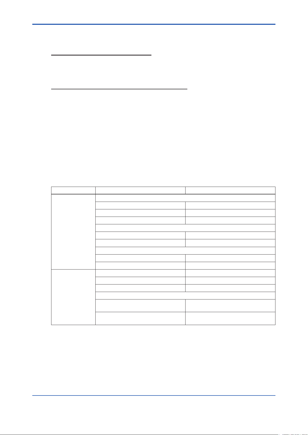
Table 2.2.1 Verication Items
Mode Verication Item Description
Standard VF Circuit (*3)
Magnetic Circuit Checks the Magnetic Circuit.
Excitation Circuit Checks the Excitation Circuit.
Calculation Circuit Checks the Calculation Circuit.
Device Status (*3)
Alarm Check Checks occurring Alarms.
Alarm History Checks historical Alarms.
Physical Appearance
Flowtube Checks the Flowtube appearance.
Converter Checks the Converter appearance.
Enhanced VF Current Output (*4) Checks the Current Output.
Pulse Output (*4) Checks the Pulse Output.
Converter (*4) Checks the Converter Accuracy.
Insulation Resistance
Coil
Signal (Electrode)
Checks the Excitation Coil.
(Remote Flowtube Only)
Checks the Insulation Resistance.
(Remote Flowtube Only)
*1: Online: The status in which the software communicates with a device.
*2: Ofine: The status in which the software does not communicate with a device.
The communication status between FieldMate and AXF can be conrmed on the FieldMate window.
*3: These items are checked only when Verication Tool is in “online” mode.
*4: When Verication Tool is in “ofine” mode, manual setting is necessary.
IM 01R01A11-01EN
<2 OUTILINE>
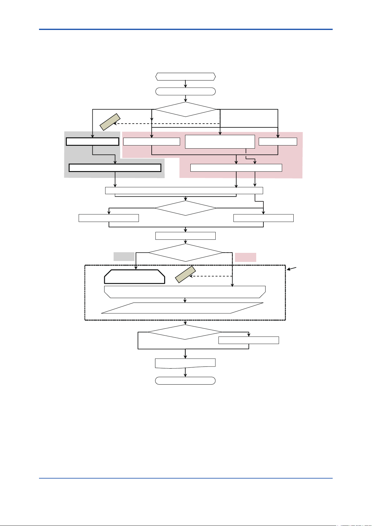
2.3 Operation Procedure
Figure 2.3.1 summarizes operation procedure.
To complete “Standard VF”, start-up Verication Tool from “Segment Viewer”. See 4.1.
1 to 3 PREPARATION
4 START-UP
2-4
Online Offline
IMPOSSIBLE
4.1 Segment Viewer 4.2 Device Navigator
No. New data Yes
5.3 General Information
Online
6.2 Standard VF
(Mandatory)
FieldMate and AXF
5 LAUNCHING
Use the existing data?
6.1 Main Screen
Verification Tool and AXF
6.3 Enhanced VF
4.3 Verification Data
in “Device Maintenance Info”
Verification Tool and AXF: OfflineVerification Tool and AXF: Online
IMPOSSIBLE
(Optional)
4.4 History
5.2 Load
Offline
Verification
Operation
No Yes
Figure 2.3.1 Operation Procedure
6.4 Result
Save the verification data ?
6.1.3 Print out
8 TERMINATION
6.1.2 Save
F020301.ai
IM 01R01A11-01EN

<3 PREPARATION>
3 PREPARATION
3-1
WARNING
• Before running the Verication Tool, loop should be set to manual mode in the host system.
• The following applications may cause inadequate results:
- Signicantly-low ow rate
- Slurry liquid
- Stray current
• When “unexpected issue (*1)” occurs while running Verication Tool, follow “8.2 Unexpected Termination” and “9 Communication Error”
*1: “Unexpected issue” means disconnection between AXF and PC:
• Physical disconnection between AXF and PC
• Forced shutdown of PC
• Unforeseen AXF power-off
IM 01R01A11-01EN
<3 PREPARATION>
3.1 Package and Installation
Regarding the packaging and installation procedure, refer to IM 01R01A01-01E Part B.
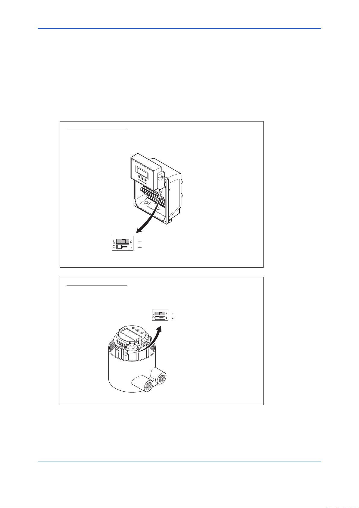
3.2 AXF Write Protect Cancellation
3.2.1 Before Verication
1) AXF parameters are changed during the verication process. Cancel the write protect
switch.
Hardware switch off
Set the "Write Protect Switch" to "Enable" before this verification.
Return the switch to the original position after this verification is
complete.
3-2
Switch 1
Switch 2
Enable Protect
(A) AXFA11
2 Burnout setting switch
1 Write protect setting switch
F030201-A.ai
Hardware switch off
Set the "Write Protect Switch" to "Enable" before this verification.
Return the switch to the original position after this verification is
complete.
Switch 1
Switch 2
Enable Protect
(B) AXFA14 or AXF Integral Flowmeter
Figure 3.2.1 Write Protect Cancellation
2 Burnout setting switch
Write protect setting switch
1
F030201-B.ai
2) After the verication is complete, return the switch to the original position.
IM 01R01A11-01EN
<3 PREPARATION>
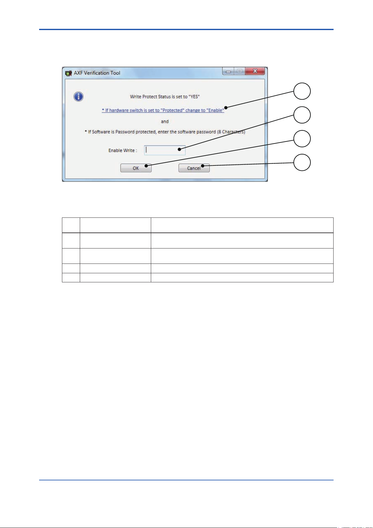
3.2.2 During Verication
1) If the AXF write protect function is set to “Protect” during the verication, Figure 3.2.2 will be
displayed.
Figure 3.2.2 “Write Protect Cancellation” Dialog
3-3
1
2
3
4
F030202.ai
Table 3.2.1 “Write Protect Cancellation” Dialog
Item
No.
1 ‘If hardware….’
2 Enable Write
3 OK Runs the software protection cancellation.
4 Cancel Cancels ‘Write Protect cancellation’
Item Name Description
Shows the gure of hardware switch. See Figure 3.2.1.
Click the text.
Cancels the software protection of the device.
Enter the password.
2) Set the “Write Protect Switch” to “Enable” .
Then, enter the password in (2) and click “OK (3)” in Figure 3.2.2.
3) Return the switch to the original position after this verication is complete.
IM 01R01A11-01EN

Blank Page
<4 START-UP FROM FieldMate>
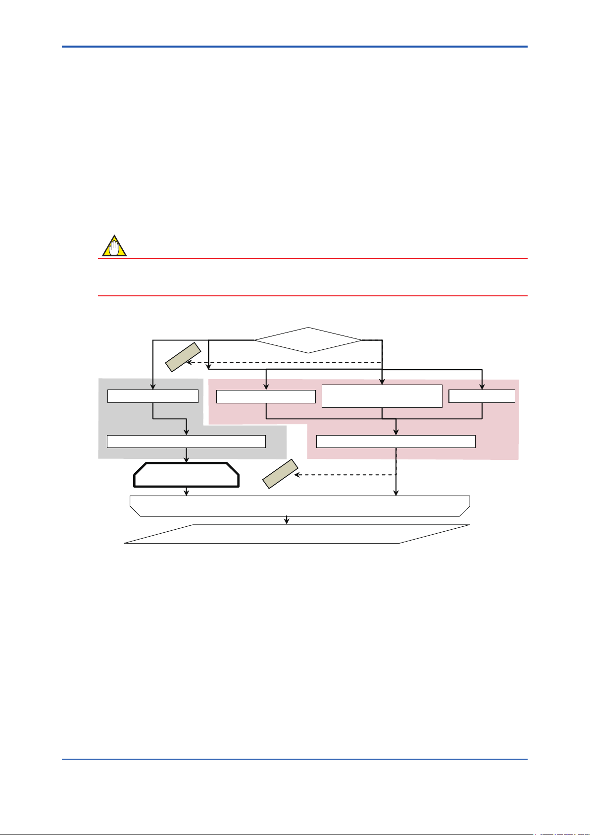
4 START-UP FROM FieldMate
Verication Tool can be started by the following:
■ From “Segment Viewer” (FieldMate is online to AXF), see 4.1.
■ From “Device Navigator”, see 4.2.
■ From “Verication Data” in “Device Maintenance Info”, see 4.3.
■ From “History”, see 4.4.
Select the start-up procedure depending on the items to be veried and connection status be-
tween FieldMate and AXF.
NOTE
• To run Verication Tool in “online” mode, start the Verication Tool from “Segment Viewer”.
• To complete Standard VF, start Verication Tool from “Segment Viewer”.
4-1
Online
IMPOSSIBLE
4.1 Segment Viewer
6.2 Standard VF
(Mandatory)
Figure 4.1.1 “Start-up” Procedure
FieldMate and AXF
4.2 Device Navigator
IMPOSSIBLE
6.3 Enhanced VF
(Optional)
6.4 Result
Offline
4.3 Verification Data
in “Device Maintenance Info”
Verification Tool and AXF: OfflineVerification Tool and AXF: Online
4.4 History
F040101.ai
IM 01R01A11-01EN
<4 START-UP FROM FieldMate>
4-2
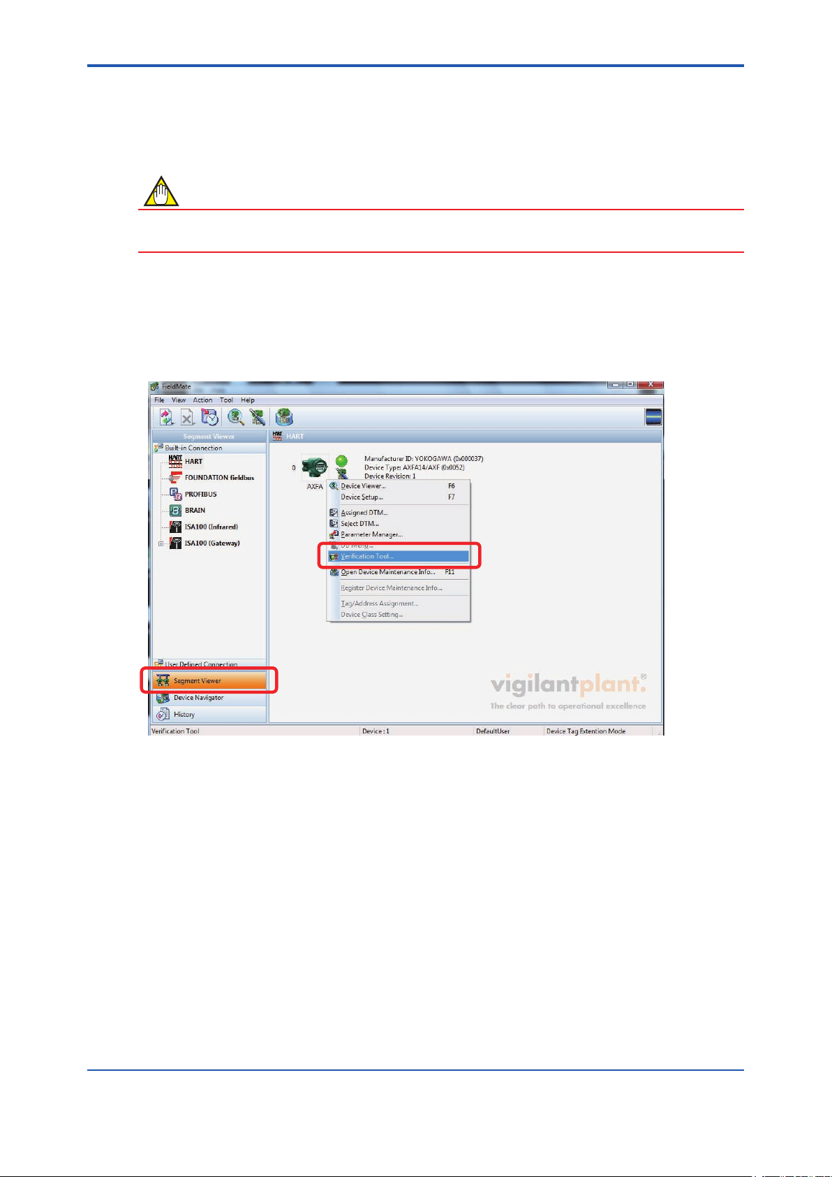
4.1 From “Segment Viewer” (AXF is reading in “online” mode in FieldMate)
NOTE
Set the device address to 0. Verication Tool can be started only when the device address is set
to 0. For details on how to set the device address, refer to 9.2.
From “Segment Viewer”, “Verication Tool” can be started by either method (A) or (B).
(A) By right-clicking
Right-click on the target (AXF) icon displayed at “Segment Viewer”, and select “Verication Tool”.
Figure 4.1.2 Start-up from “Segment Viewer” by Right-clicking
F040102.ai
IM 01R01A11-01EN
<4 START-UP FROM FieldMate>
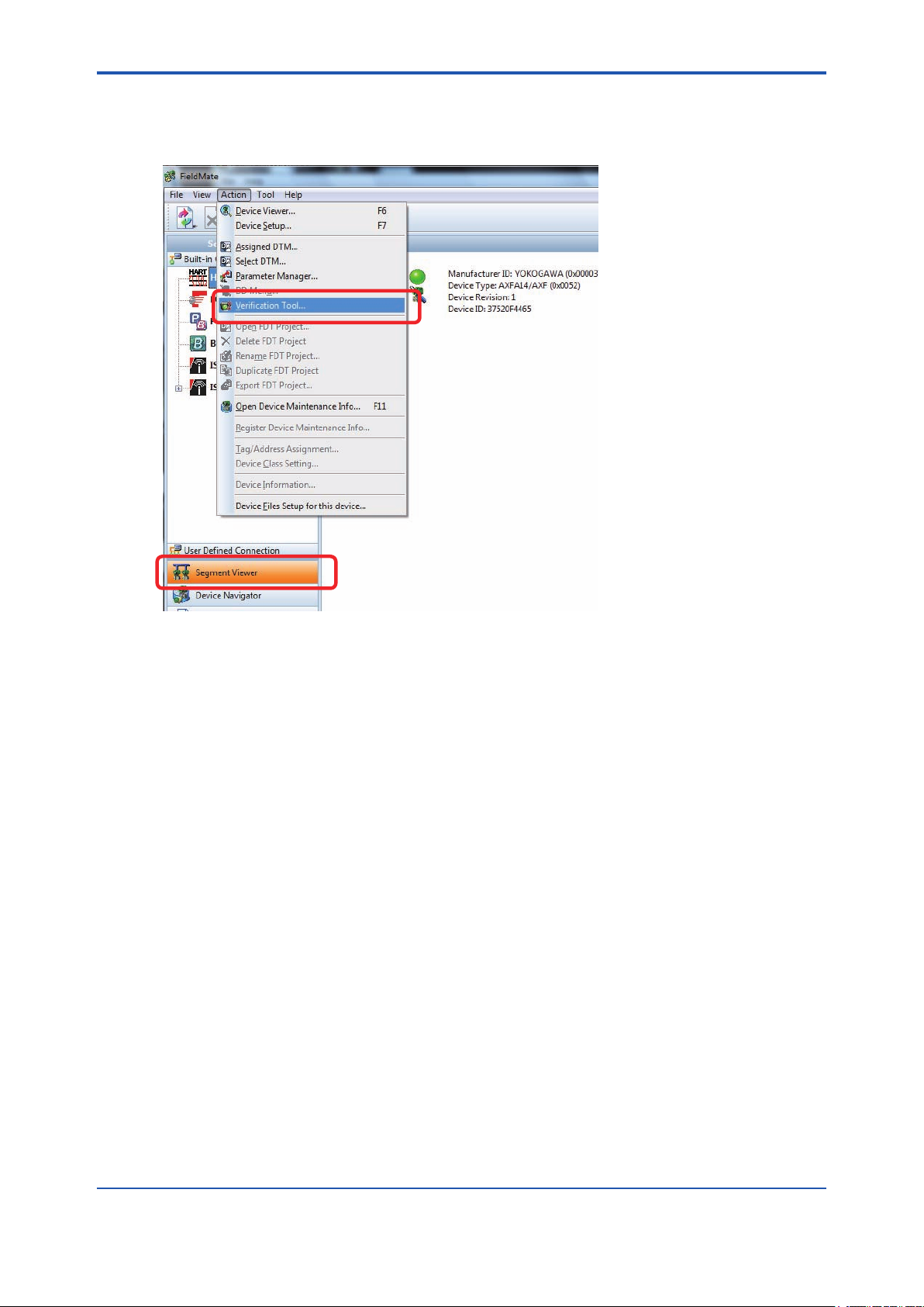
(B) By selecting menu “Action”
Select the target (AXF) icon displayed at “Segment Viewer”, and in the “FieldMate” menu bar,
select “Action - Verication Tool”.
4-3
F040103.ai
Figure 4.1.3 Start-up from “Segment Viewer” by Selecting the “Action” Menu
IM 01R01A11-01EN
<4 START-UP FROM FieldMate>
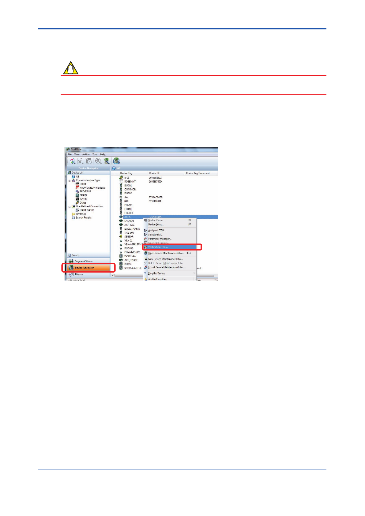
4.2 From “Device Navigator”
NOTE
When Verication Tool is started from “Device Navigator”, it will be in “ofine” mode even if the
AXF is in “online” mode in FieldMate.
From “Device Navigator”, “Verication Tool” can be started by either method (A) or (B).
(A) By right-clicking
Right-click on the target (AXF) icon displayed at “Device Navigator”, and select “Verication Tool”.
4-4
F040201.ai
Figure 4.2.1 Start-up from “Device Navigator” by Right-clicking
IM 01R01A11-01EN
<4 START-UP FROM FieldMate>
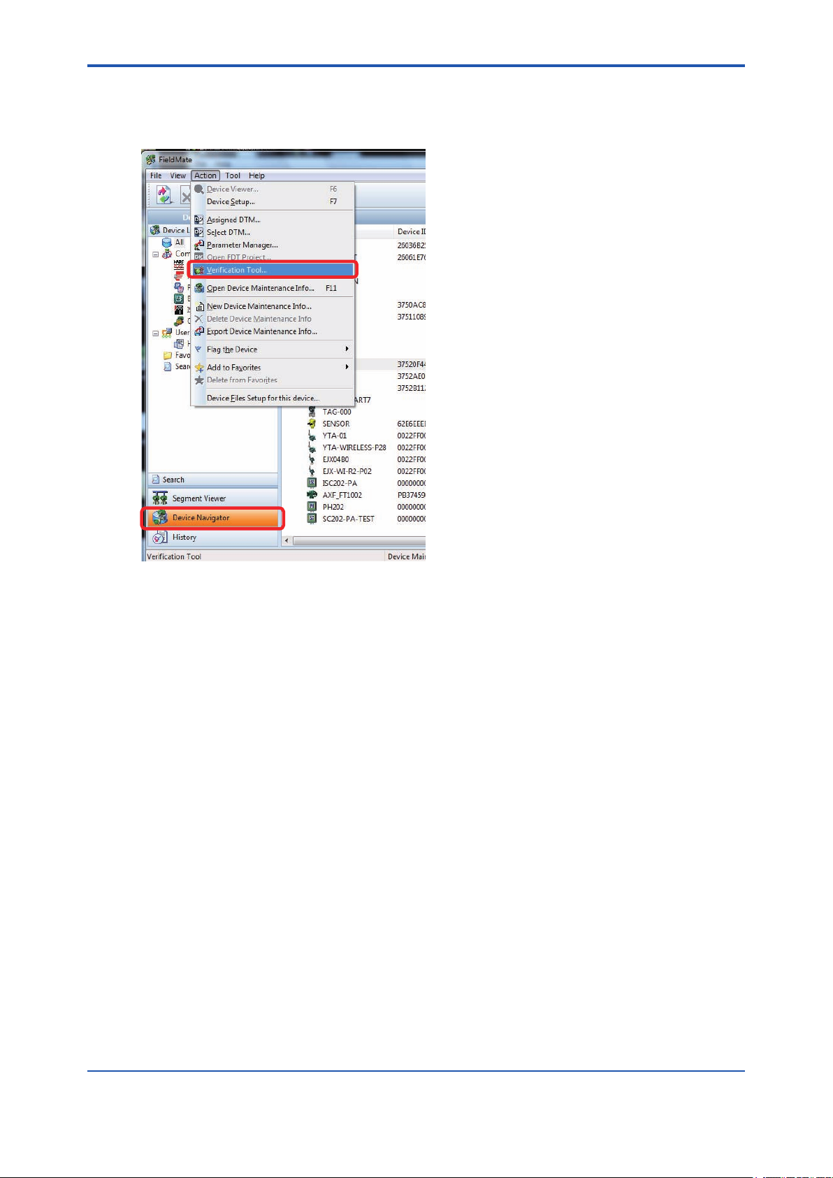
(B) By selecting menu “Action”
Select the target (AXF) icon displayed at “Device Navigator”, and in the “FieldMate” menu bar,
select “Action - Verication Tool”.
4-5
F040202.ai
Figure 4.2.2 Start-up from “Device Navigator” by Selecting the “Action” Menu
IM 01R01A11-01EN
<4 START-UP FROM FieldMate>
4.3 From “Verication Data” in “Device
Maintenance Info”
NOTE
When Verication Tool is started from “Device Maintenance Info”, it will be in “ofine” mode even
if the AXF is in “online” mode in FieldMate.
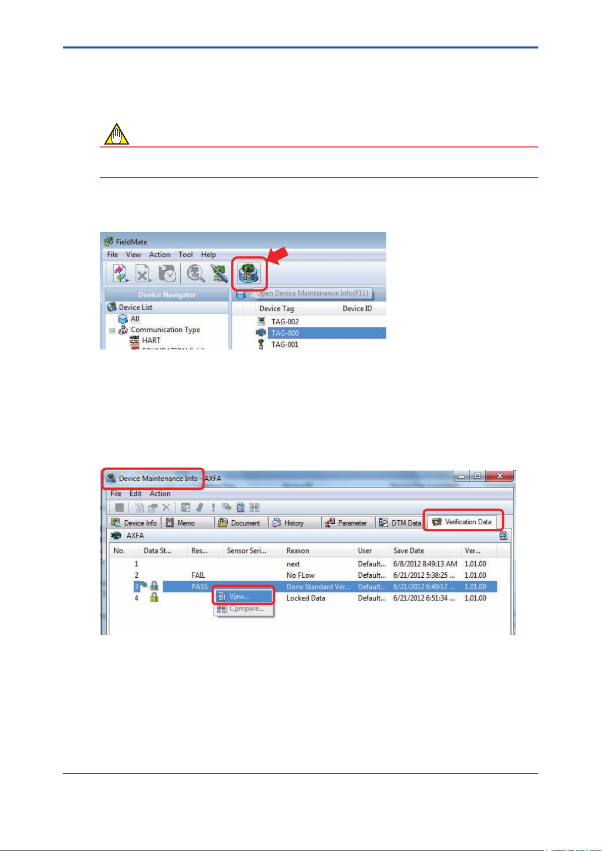
From the “Verication Data” tab in “Device Maintenance Info”, “Verication Tool” can be started
by either method (A) or (B). Select the target (AXF) icon and click the “Open Device Maintenance
Info” icon. The “Device Maintenance Info” screen appeares.
4-6
Figure 4.3.1 “Device Maintenance Info” Icon
(A) By right-clicking
Select the “Verication Data” tab on the “Device Maintenance Info” screen. Right-click on the
verication data listed on the “Verication Data” tab under “Device Maintenance Info, and select
“View”. Verication Tool is started up and the selected verication data is loaded.
Figure 4.3.2 Start-up from “Verication Data” in “Device Maintenance Info” by Right-clicking
F040301.ai
F040302.ai
IM 01R01A11-01EN
<4 START-UP FROM FieldMate>
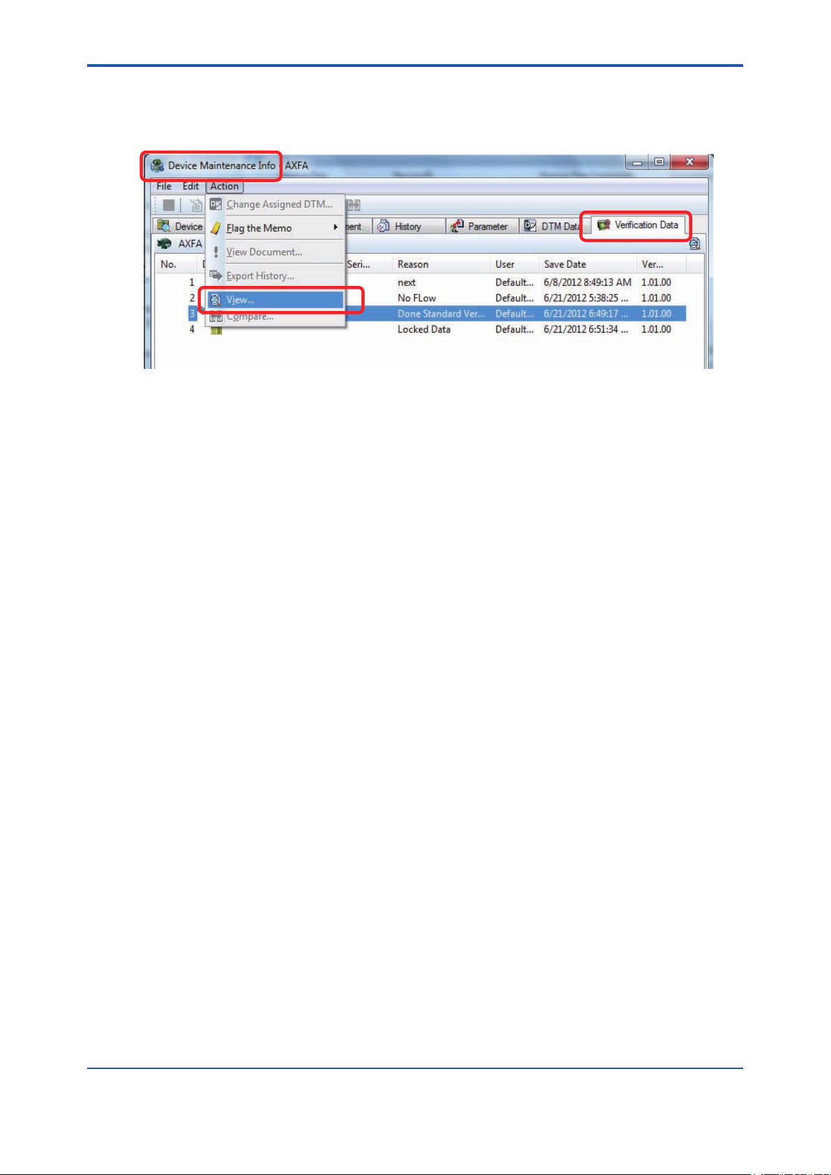
(B) By selecting menu “Action”
In the “Device Maintenance Info” menu bar, select “Action”-“View”. Verication Tool is started up
and the selected verication data is loaded.
Figure 4.3.3 Start-up from “Verication Data” in “Device Maintenance Info” by Selecting the “Action”
Menu
4-7
F040303.ai
IM 01R01A11-01EN
<4 START-UP FROM FieldMate>
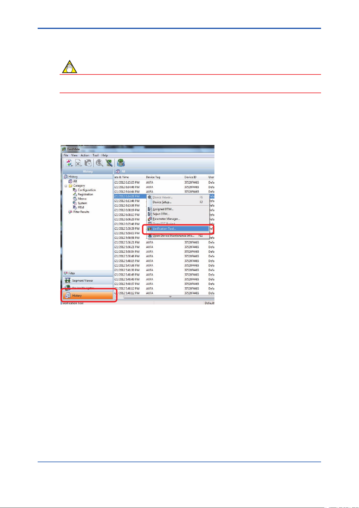
4.4 From “History”
NOTE
When Verication Tool is started from “History”, it will be in “ofine” mode even if the AXF is in
“online” mode in FieldMate.
From “History”, “Verication Tool” can be started by either method (A) or (B).
(A) By right-clicking
Right-click on the target device (AXF) listed in “History”, and select “Verication Tool”.
4-8
Figure 4.4.1 Start-up from “History” by Right-clicking
F040401.ai
IM 01R01A11-01EN
<4 START-UP FROM FieldMate>
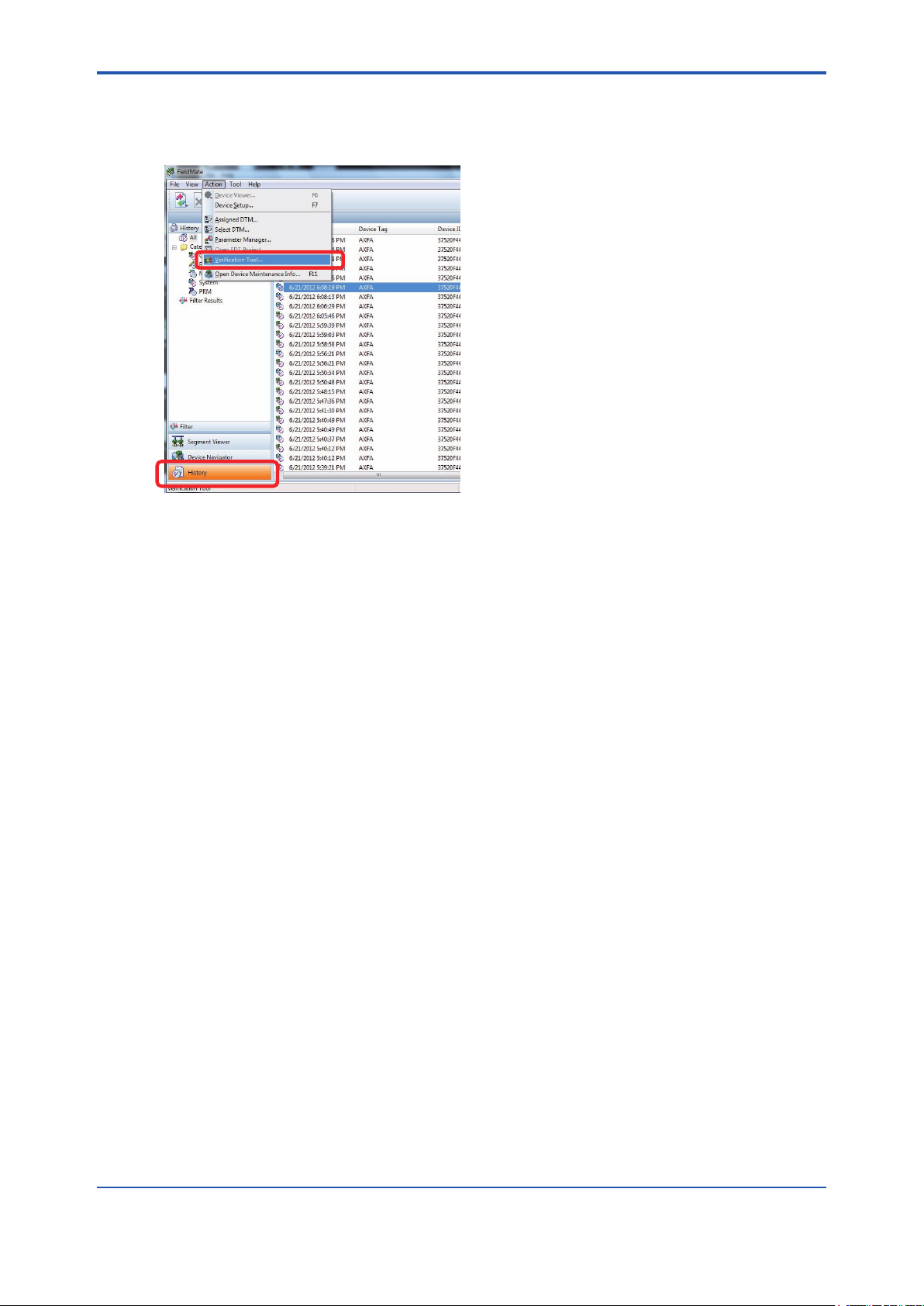
(B) By selecting menu “Action”
Select the target (AXF) listed in “Device Maintenance Info”, and in the “FieldMate” menu bar,
select “Action”-“Verication Tool”.
F040402.ai
Figure 4.4.2 Start-up from “History” by Selecting the “Action” Menu
4-9
IM 01R01A11-01EN

Blank Page
Loading...