


User’s
Manual
Model SC100
Panel Mount Conductivity Converter
IM 12D11A01-01E
IM 12D11A01-01E
1st Edition
Safety Precautions
r Introduction
This manual covers the specifications, installation, operation and maintenance of the panel-mount version of the SC100 Conductivity converter. Please read this before using the SC100.
There are manuals for the related EXA100 series as follows: Refer to them as required.
Model code |
Manual Name |
|
IM No. |
PH100 |
Panel Mount pH Converter |
IM 12 B11A01-01E |
|
OR100 |
Panel Mount ORP Converter |
IM 12 C11A01-01E |
|
SC100 |
Panel Mount Conductivity Converter |
IM 12 D11A01-01E |
|
PH10FP |
KCl Refillable pH Sensor |
IM 12 B11C01-01E |
|
PH10RP |
KCl Replenish-free pH Sensor |
IM 12 B11C02-01E |
|
OR10FP |
KCl Refillable ORP Sensor |
IM 12 C11C01-01E |
|
OR10RP |
KCl Replenish-free ORP Sensor |
IM 12 C11C02-01E |
|
SC10XB |
Conductivity Sensor for SC100 |
IM 12 D11C01-01E |
|
WTB100 |
Terminal Box for EXA100 |
IM 12 B11E01-01E |
|
WF100 |
Extension Cable for EXA100 |
IM 12 |
B11F01-01E |
PH10HLD |
Immersion Holder for EXA100 |
IM 12 |
B11D01-01E |
PH10HG |
Guide-pipe Holder for EXA100 |
IM 12 |
B11D02-01E |
T000.eps
IM 12D11A01-01E
1st Edition: June. 2003 (YK)
All Rights Reserved, Copyright © 2003, Yokogawa Electric Corporation
IM 12D11A01-01E
i

rFor the safe use of this equipment
(1)About This Manual
•This manual should be passed on to the end user.
•The contents of this manual are subject to change without prior notice.
•The contents of this manual shall not be reproduced or copied, in part or in whole, without permission.
•This manual explains the functions contained in this product, but does not warrant that they will suit the particular purpose of the user.
•Every effort has been made to ensure accuracy in the preparation of this manual. However, should any errors or omissions come to the attention of the user, please contact the nearest Yokogawa Electric representative or sales office.
•This manual does not cover the special specifications. This manual may be left unchanged on any change of specification, construction or parts when the change does not affect the functions or performance of the product.
•If the product is used in a manner not specified in this manual, the safety of this product may be impaired.
(2) Safety and Modification Precautions
• Follow the safety precautions in this manual when using the product to ensure protection and safety of personnel, product and system containing the product.
(3) The following safety symbols are used on the product as well as in this manual.
DANGER
This symbol indicates that the operator must follow the instructions laid out in this manual in order to avoid the risk of personnel injury, electric shock, or fatalities. The manual describes what special care the operator must exercise to avoid such risk.
 WARNING
This symbol indicates that the operator must refer to the instructions in this manual in order to prevent the instrument (hardware) or software from being damaged, or a system failure from occurring.
 CAUTION
This symbol draws attention to information essential for understanding the operation and functions.
Tip
This symbol gives information that complements the current topic.
SEE ALSO
This symbol identifies a source to which to refer.
Protective Ground Terminal
Function Ground Terminal (Do not use this terminal as the protective ground terminal.)
Alternating current
ii |
IM 12D11A01-01E |
Safety Precautions
rNOTICE and Cautions
•Check specifications
When the instrument arrives, unpack the package with care and check that the instrument has not been damaged during transportation. In addition, please check that the specification matches the order, and required accessories are not missing. Specifications can be checked by the model codes on the nameplate. Refer to Chapter 1.2 Specifications for the list of model codes.
•Details on operation parameters
When the SC100 panel mount Conductivity Converter is operated without any key operation at the user site, it will work based on the operation parameters (initial data Table 5.1 to 5.3) set before shipping from the factory.
Ensure that the initial data is suitable for the operation conditions before conducting analysis. Where necessary, set the instrument parameters for appropriate operation. For details of setting data, refer to chapters 4 to 6.
When the operation parameters are changed, it is recommended to note down the changed setting data.
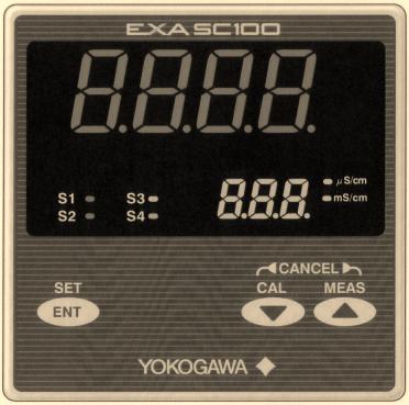
Front Panel of SC100
IM 12D11A01-01E |
iii |

LED Display Symbols
• Alphanumerics are represented as follows on the LED display
Alphanumerics LED Display Alphanumerics LED Display Alphanumerics LED Display
A |
N |
0 |
B |
O |
1 |
C |
P |
2 |
D |
Q |
3 |
E |
R |
4 |
F |
S |
5 |
G |
T |
6 |
H |
U |
7 |
I |
V |
8 |
J |
W |
9 |
K |
X |
|
L |
Y |
|
M |
Z |
|
iv |
IM 12D11A01-01E |
Safety Precautions
r After-sales Warranty
dFor repair during the warranty period, carry or send the product to the local sales representative or service office. Yokogawa will replace or repair any damaged parts and return the product to you.
dBefore returning a product for repair under warranty, give us information of the model name and serial number and a description of the problem. Any diagrams or data explaining the problems would also be appreciated.
dIf we replace the product with a new one, we won’t provide you with a repair report.
dYokogawa warrants the product for the period stated in the purchase quotation. Yokogawa shall conduct warranty service based on its standard. When the customer site is outside of the service area, a fee for dispatching the maintenance engineer will be charged to the customer.
dIn the following cases, customer will be charged for repair fee regardless of warranty period.
•Failure of components which are out of scope of warranty stated in instruction manual.
•Failure caused by usage of software, hardware or auxiliary equipment, which Yokogawa Electric did not supply.
•Failure due to improper or insufficient maintenance by user.
•Failure due to modification, misuse or outside-of-specifications operation which Yokogawa does not authorize.
•Failure due to power supply (voltage, frequency) being outside specifications or abnormal.
•Failure caused by any usage out of scope of recommended usage.
•Any damage from fire, earthquake, storms and floods, lightning, disturbances, riots, warfare, radiation and other natural changes.
dYokogawa does not warrant conformance with the specific application at the user site. Yokogawa will not bear direct/indirect responsibility for damage due to a specific application.
dYokogawa Electric will not bear responsibility when the user configures the product into systems or resells the product.
dOur maintenance service and the supply of repair parts will be covered for five years after the production ends. For product repair, please contact the nearest sales office described in this instruction manual.
IM 12D11A01-01E |
v |
vi |
IM 12D11A01-01E |

Contents
r Introduction ...................................................................................................................... |
|
i |
|
r For the safe use of this equipment ................................................................................ |
ii |
||
r NOTICE and Cautions .................................................................................................. |
iii |
||
r After-sales Warranty ...................................................................................................... |
v |
||
1. |
Overview ..................................................................................................................... |
|
1-1 |
|
1.1 |
EXA SC100 conductivity converter ............................................................... |
1-1 |
|
1.2 |
Check the specifications ................................................................................. |
1-1 |
|
1.3 |
Features of the EXA SC100 conductivity converter ...................................... |
1-2 |
|
1.4 |
Standard Specifications ................................................................................... |
1-2 |
2. |
Preparation for Operation ........................................................................................ |
2-1 |
|
|
2.1 |
Unpacking ....................................................................................................... |
2-1 |
|
2.2 |
Choosing an Installation Location .................................................................. |
2-1 |
|
2.3 |
External Dimensions ....................................................................................... |
2-2 |
|
2.4 |
Panel Cutout Dimensions ................................................................................ |
2-3 |
|
2.5 |
Mounting ......................................................................................................... |
2-3 |
3. |
Wiring .......................................................................................................................... |
|
3-1 |
|
3.1 |
Direction of cable terminals fixing ................................................................. |
3-2 |
|
3.2 |
Noise prevention ............................................................................................. |
3-3 |
|
3.3 |
Wiring Terminal Diagram ............................................................................... |
3-4 |
|
|
3.3.1 Use of EXA SC100 in combination with the SC10XB dedicated |
|
|
|
conductivity sensor .................................................................................. |
3-5 |
|
|
3.3.2 Use of EXA100 in combination with the SC4A conductivity sensor .... |
3-6 |
|
3.4 |
Conductivity sensor detector wiring ............................................................... |
3-8 |
|
|
3.4.1 Connection of the SC100 converter and the SC10XB conductivity |
|
|
|
sensor ....................................................................................................... |
3-8 |
|
|
3.4.2 Connection of SC100 converter and SC4A conductivity sensor ........... |
3-8 |
|
3.5 |
Wiring the WF100 Extension Cable ............................................................... |
3-9 |
|
3.6 |
Output Signal Cable Wiring ........................................................................... |
3-9 |
|
3.7 |
Contact output wiring. .................................................................................... |
3-9 |
|
|
3.7.1 Wiring when S1 is used .......................................................................... |
3-9 |
|
|
3.7.2 Wiring for S2 (for two-contact-output specification) or S2, S3 and |
|
|
|
S4 (for four-contact output specification) ............................................. |
3-11 |
|
3.8 |
Power and Ground Wiring ............................................................................ |
3-12 |
4. Overview of Operation Panel ................................................................................... |
4-1 |
||
|
4.1 |
Overviews of names and functions of operation panel keys ......................... |
4-1 |
|
4.2 |
Key Operation ................................................................................................. |
4-2 |
|
4.3 |
Switching mode to be Displayed .................................................................... |
4-3 |
IM 12D11A01-01E |
vii |
|
4.4 |
Display examples ............................................................................................ |
4-4 |
|
|
|
4.4.1 Display in Initial model ........................................................................... |
4-4 |
|
|
|
4.4.2 Display in Measurement mode ................................................................ |
4-5 |
|
|
|
4.4.3 |
Calibration mode ..................................................................................... |
4-6 |
|
|
4.4.4 |
Setting mode ............................................................................................ |
4-7 |
5. |
Operation .................................................................................................................... |
|
|
5-1 |
|
5.1 |
Start up ............................................................................................................ |
5-1 |
|
|
|
5.1.1 |
Check wiring ........................................................................................... |
5-1 |
|
|
5.1.2 Start up Conductivity Converter ............................................................. |
5-1 |
|
|
|
5.1.3 |
Data Setting ............................................................................................. |
5-1 |
|
|
5.1.4 |
Preparation for Operation ........................................................................ |
5-8 |
|
5.2 |
Test Operation ................................................................................................. |
5-8 |
|
|
5.3 |
Normal Operation ............................................................................................ |
5-8 |
|
|
5.4 |
Stopping and Restarting Operation ................................................................. |
5-8 |
|
6. |
Settings ........................................................................................................................ |
|
|
6-1 |
|
6.1 |
Setting Cell Constants ..................................................................................... |
6-1 |
|
|
|
6.1.1 How to set cell constant .......................................................................... |
6-1 |
|
|
|
6.1.2 |
Cell Constant ........................................................................................... |
6-2 |
|
|
6.1.3 |
Cell Constant Retention ........................................................................... |
6-2 |
|
6.2 |
Temperature Compensation Setting ................................................................ |
6-2 |
|
|
|
6.2.1 |
Determining Temperature Coefficient .................................................... |
6-3 |
|
|
6.2.2 |
Setting Temperature Coefficient ............................................................. |
6-4 |
|
6.3 |
Compensation for Wiring Resistance ............................................................. |
6-6 |
|
|
|
6.3.1 |
Setting Wiring Resistance ....................................................................... |
6-6 |
|
|
6.3.2 |
Temperature Calibration .......................................................................... |
6-6 |
|
6.4 |
Zero Calibration (Calibration in Air) .............................................................. |
6-7 |
|
|
|
6.4.1 Procedure for Zero Calibration (Calibration in Air) ............................... |
6-7 |
|
|
6.5 |
Calibration with Standard Solution ................................................................. |
6-9 |
|
|
|
6.5.1 Calibration with Standard Solution (when using NaCl for standard |
|
|
|
|
|
solution) ................................................................................................. |
6-10 |
|
|
6.5.2 Calibration (by comparison with reference conductivity meter) .......... |
6-12 |
|
|
|
6.5.3 “Procedure for Calibration with Standard Solution”. ........................... |
6-12 |
|
|
6.6 |
Canceling Calibration .................................................................................... |
6-14 |
|
|
6.7 |
Escaping from Error Occurrences During Calibration ................................. |
6-14 |
|
|
|
6.7.1 Conditions which cause errors during calibration: ............................... |
6-14 |
|
|
|
6.7.2 |
How errors are displayed when errors occurs during calibration: ...... |
6-14 |
|
|
6.7.3 Procedure for Recovering from Errors ................................................. |
6-14 |
|
7. |
Cleaning and Maintenance ....................................................................................... |
7-1 |
||
|
7.1 |
Periodic Maintenance ...................................................................................... |
7-1 |
|
|
|
7.1.1 |
Sensor Cleaning ....................................................................................... |
7-1 |
|
|
7.1.2 |
Calibration ............................................................................................... |
7-1 |
|
7.2 |
Checks and Preventive Maintenance .............................................................. |
7-2 |
|
viii |
IM 12D11A01-01E |
8. Troubleshooting .......................................................................................................... |
|
8-1 |
8.1 |
Determining whether trouble is in Sensor or Converter ................................ |
8-1 |
8.2 |
Error display .................................................................................................... |
8-6 |
8.3 |
Things to do when an error is detected .......................................................... |
8-7 |
|
8.3.1 Error E-1 Conductivity input is out of measurement range ................... |
8-7 |
|
8.3.2 Error E-2 Temperature measurement is out of range ............................. |
8-7 |
|
8.3.3 Error E-3 Temperature sensor abnormal ................................................. |
8-7 |
|
8.3.4 Error E-4 Converter abnormal ................................................................ |
8-8 |
|
8.3.5 Error E-5 Temperature Compensation Out of Range ............................. |
8-8 |
|
8.3.6 Calibration Error C-1 Standard solution temperature out of range ........ |
8-8 |
|
8.3.7 Calibration Error C-2 Calibration abnormal ........................................... |
8-8 |
|
8.3.8 Calibration Error C-3 Zero calibration abnormal ................................... |
8-9 |
|
8.3.9 Calibration Error C-4 The used standard liquid conductivity out of |
|
|
measurement range .................................................................................. |
8-9 |
8.4 |
Things to do when measurement value is abnormal. ..................................... |
8-9 |
Revision Record .................................................................................................................... |
|
i |
IM 12D11A01-01E |
ix |
x |
IM 12D11A01-01E |
1. Overview
1.Overview
1.1EXA SC100 conductivity converter
The EXA SC100 conductivity converter is a panel-mount unit with built-in generalpurpose preamp, large 4-digit LED display for measured value and 4-digit LED display for settings.
1.2Check the specifications
The model code and suffix codes are shown below. Make sure that the supplied SC100 is the same as what you ordered.
Model |
|
Suffix code |
Option code |
Description |
|
|
|
|
|
|
|
SC100 |
|
|
|
|
Panel mount conductivity converter |
|
|
|
|
|
|
22222 |
-A |
|
Always -A |
||
|
|
|
|
|
|
Label language |
|
-E |
|
English |
|
|
|
|
|
|
|
|
|
-J |
|
Japanese |
|
|
|
|
|
|
|
Contact output |
-21 |
|
2 contact outputs |
||
|
|
|
|
|
|
|
-41 |
|
4 contact outputs |
||
|
|
|
|
|
|
22222 |
|
|
-NN |
|
Always -NN |
|
|
|
|
|
|
Option |
|
|
Unit |
/UNT |
S/m |
|
|
|
|
|
|
|
|
|
Construction |
/65 |
IP65 |
|
|
|
|
|
|
T02.EPS
IM 12D11A01-01E |
1-1 |
1.3Features of the EXA SC100 conductivity converter
(1)Large 4-digit display. Both measured conductivity value and temperature can be displayed at the same time.
(2)You can select either two output contacts or four ; and you can select each contact output type from : high, low, high high, low low, and high high / low low.
(3)An isolated 4 to 20 mA analog output of measured value.
(4)The operation panel is rated for operation in an IP55. IP65 is optional.
(5)96 mm x 96 mm DIN size panel-mount analyzer. Depth is 120 mm and weight is 600 g.
(6)Full set of self-diagnostic functions with indication of errors such as "out of measurement range", "converter abnormal", "calibration-time error".
1.4Standard Specifications
Measurement: Conductivity of solution Measuring range: 0.05mS/cm to 200 mS/cm
Note: Measuring range is defined by the sensor to be used. Maximum range of applicable sensors (SC10XB and SC4A) is 0 to 2.0 mS/cm.
Indication |
|
|
|
Display: |
Digital (LED) |
|
|
Range: |
0.000mS/cm to 200.0 mS/cm |
||
Indication: |
Conductivity reading, setting, status, temperature (range: -10 to 1108C) |
||
Input signal |
|
|
|
Conductivity input range: |
|
||
Minimum: |
5 mS/cm3K (K: cell constant) |
||
Maximum: |
50 mS/cm3K (K: cell constant) |
||
Temperature input: |
Pt1000/Pt100 |
||
Temperature input range: |
-10 to 1108C |
||
Transmission signal output
Number of output points: 1 point (for output of conductivity reading only)
Output signal: |
4 to 20 mA DC, isolated |
Load resistance: |
600 V or less |
Transmission signal range: Configurable within measuring range (initial setting : 0 to
200 mS/cm) |
|
Minimum span: 0 to 0.2 mS/cm |
|
Maximum span: 0 to 200 mS/cm |
|
Note: Configurable range depends on the sensor |
to be used. |
Maintenance output signal: Output hold "enabled/disabled" selectable |
|
Hold output value: Last measured value/preset value |
(2.0 to 20.8 mA) selectable |
Fail output signal: Downscale burndown (2 mA) "enabled/disabled" selectable
1-2 |
IM 12D11A01-01E |
1. Overview
Contact output
Contact type : Relay contact output
Number of contacts : 2 or 4 outputs (must be specified when ordering) Contact action : On/Off action
Contact functions : Selectable; High, low, high-high, low-low, high-high/low-low limit alarms, FAIL
Contact output hysteresis : 0 to 100% (configurable) Contact output delay time : 0 to 200 seconds (configurable)
Contact rating :
When 2 contact outputs specified
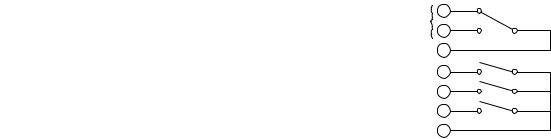
S1 : 240 VAC 3A or 30 V DC 3A (resistance load), Form C (NC/NO/COM, 3 terminals)
S2 : 240 VAC 3A or 30 V DC 3A (resistance load), Form A (NO/COM, 2 terminals)
When 4 contact outputs specified
S1 : 240 VAC 3A or 30 V DC 3A (resistance load), Form C (NC/NO/COM, 3 terminals)
S2, S3, S4 : 240 V AC 3A or 30 V DC 3A (resistanceload), Form A, shared common Maximum load current on common is 3A.
Contact status:
Table 1.1
|
|
|
Function selected |
|
|
|
|
|
Contact |
H, L, HH, LL, HH/LL limit alarms |
|
FAIL |
|
|
|||
|
|
Power off |
Power on |
Power off |
Power on |
|||
|
|
No alarm |
Alarm |
No alarm |
Alarm |
|||
|
|
|
|
|||||
S1 |
NO-COM |
Open |
Open |
Closed |
Open |
Closed |
Open |
|
|
NC-COM |
Closed |
Closed |
Open |
Closed |
Open |
Closed |
|
S2 |
Open |
Open |
Closed |
Open |
Closed |
Open |
||
S3 when specified |
Open |
Open |
Closed |
Open |
Closed |
Open |
||
S4 when specified |
Open |
Open |
Closed |
Open |
Closed |
Open |
||
Note: When a contact is activated, the LED on display panel turns on.
Terminal |
|
|
NC |
|
1 |
S1 |
NO |
|
2 |
COM |
3 |
S2 |
4 |
S3 |
5 |
S4 |
6 |
COM |
7 |
Ambient temperature : -5 to 45 8C
Installation altitude: 2000 m or less above sea level Storage temperature : -25 to 70 8C
Ambient humidity : 10 to 90% RH, non-condensing
Construction : Front panel : Dust-proof and drip-proof construction IP55, IP65 (when “/65” option specified)
Materials : ABS resin and polycarbonate Case color : Black
Rated Power supply : voltage : 100 to 240 V AC (610%), 50/60 Hz Power consumption : Max. 9 VA
Weight : Approx. 600g
Dimensions : 96 (W) 3 96 (H) 3 120 (D) mm Mounting : Panel mount
Panel cutout dimensions : 92 (W) 3 92 (H) mm Wiring : M3.5 screw terminal
Grounding : grounding resistance 100 V or less
IM 12D11A01-01E |
1-3 |

Conformance to Safety and Standards
Conforms to IEC1010-1: 1990 and EN61010-1: 1992. Certified for CSA1010.
The overvoltage category of each input is CAT II (IEC1010-1) Certified for UL61010C. *l
*l
"Overvoltage category (Installation category)" describes a number which defines a transient overvoltage condition. It implies the regulation for inpulse withstand voltage.
"II " applies to electrical equipment which is supplied from the fixed installation like distribution board.
"I " applies to electrical equipment which is supplied from the circuit when appropriate transient overvoltage control means (interfaces) are provided.
Note: CSA, UL are pending.
Functional specifications
Reference temperature conversion: 0.00 to 10.00%/8C or NaCl coefficient compensation
Reference temperature setting range: |
0 to 1008C |
|
Cell constant setting range: |
0.0001 to 12.00 cm-1 |
|
Temperature value adjustment (cable length correction by temperature 1-point calibration) Sensor cable length correction
Calibration function
Manual zero calibration (air calibration)
Span calibration (specified setting by specified solution, 1-point calibration) Note: Temperature indication is available during manual calibration
Self-diagnostics function
FAIL output: Measuring range failure, temperature range failure, temperature sensor failure, converter failure, invalid temperature compensation
Error indication: Calibration value failure, abnormal temperature range during calibration, calibration solution measuring range failure
Converter performance: under normal operating conditions Repeatability: 61% of span
Note: Span refers to the one of input range. Temperature reproducibility: 618C Transmission output accuracy: 60.3% of span
Note: Span refers to one of transmission signal output range. Applicable sensors:
SC10XB Conductivity Sensor for SC100 Cable lenght : 3,5,10m
Extension cable length : up to 50m (Using the WTB100 terminal box)
Note : Extension cable length means that total cable length including sensor cable is within 50m
Wetted part materials :
In applying piping adapter : SUS316, polypropylene and rigid PVC resin (SC10XB) rigid PVC resin (adapter), Viton R fluoroelastomer (O-ring for adapter)
In applying drop-in-type : SUS316, polypropylene, ridid PVC resin, silicone rubber, PPS regin chlorinated polythylene rubber (for cable seath)
SC4A 2-electrode Conductivity Sensor
Note: Refer to document GS12D08F03-01E when using SC4A sensor.
1-4 |
IM 12D11A01-01E |

2. Preparation for Operation
2.Preparation for Operation
2.1Unpacking
When the instrument arrives, unpack the package with care and check that the instrument has not been damaged during transportation. In addition, please check that the specification matches the order, and required accessories are not missing.
2.2Choosing an Installation Location
 WARNING
To minimize the danger of shock, the converter should be mounted on a panel for the converter when power is applied.
Cautions in choosing a mounting location
 CAUTION
(1)Mount the converter in a location which allows adequate space for access from the rear for wiring and the like,
(2)Ideally the converter should be on the rear of a panel, so that unauthorized personnel will not have access to the terminals,
(3)The converter should be located in a place with minimal vibration,
(4)The converter should not be exposed to corrosive gas atmospheres,
(5)Temperature should be near normal (23 8C) with minimal change,
(6)Humidity should be between 10% and 90% RH,
(7)The converter should not be exposed to direct heat radiation,
(8)The converter should not be exposed to strong magnetic fields,
(9)The converter should not be exposed to water or moisture to be condensed,
(10)The converter should not be mounted near flammable materials,
(11)The converter should not be exposed to strong UV light.
The case of the converter is made of flam-retarded polycarbonate resin, and the bezel is flam-retarded ABS resin, so the converter should not be mounted above flammable materials.
If the converter is mounted near flammable materials against our caution, cover the converter by a plated steel plate at least 1.43 mm thick, or an uncoated steel plate of thickness 1.6 mm, separating the material from the converter top, bottom, left and right sides by a clearance of least 150 mm.
IM 12D11A01-01E |
2-1 |

150 mm
150 mm
150 mm
Fig. 2.1
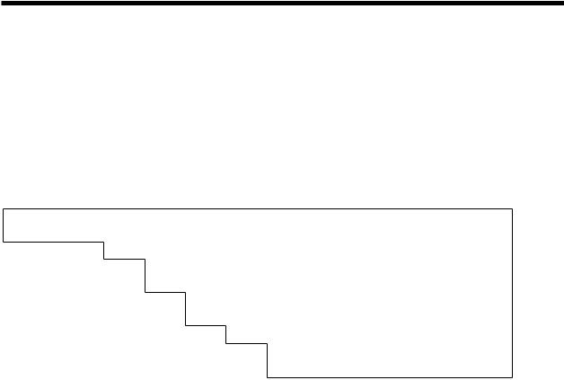
2.3External Dimensions
•SC100 Converter
11
|
EXASC100 |
|
|
S1 |
S3 |
mS/cm |
|
mS/cm |
96 |
||
S2 |
S4 |
|
|
|
CANCEL |
|
|
SET |
CAL |
MEAS |
|
ENT
96
Fig. 2.2
150 mm
F2.1.EPS
|
Unit: mm |
11-20 |
|
31-40 21-30 |
Max. |
41-50 |
91.6 |
51-60 |
|
1-10 |
|
Power supply terminal cover
111
91.6 |
111 |
Panel depth: 1 to 10
100
F2.2E.EPS
2-2 |
IM 12D11A01-01E |
2. Preparation for Operation
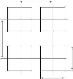
2.4Panel Cutout Dimensions
Unit : mm
125 Min.
145 Min.
92 +00.8
92+00.8
Fig. 2.3
IM 12D11A01-01E |
2-3 |
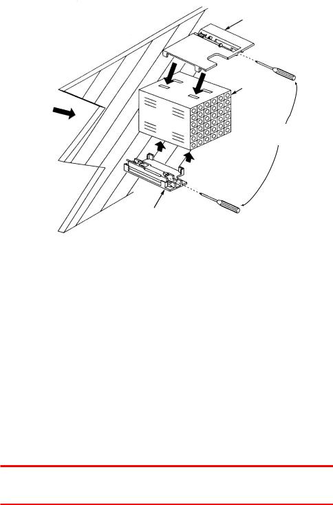
2.5Mounting
Large brackct (mount at top)
Panel
Terminal board
Insert from this
Side of panel Insert driver to tighten bracket
Small bracket (mount at bottom)
Fig. 2.4
Procedure 1
Cut panel out to mount the SC100 converter, referring to cutout dimensions shown on previous page.
Procedure 2
Insert the rear of the converter (terminal block side) in panel cutout.
Procedure 3
Mount top and bottom brackets (see figure) to fix the converter to panel. *When detector output is to be prewired, refer to Sec. 3.4(2)
 WARNING
When mounting the converter to the cutout, do not tightly fit them, do not force it because its case or mounting brackets may be damaged.
2-4 |
IM 12D11A01-01E |
2. Preparation for Operation
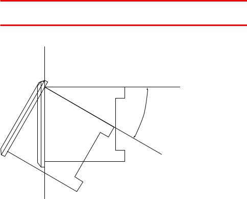
 WARNING
Install the converter within below 308 from the line perpendicular to the panel board. Do not face the front of the converter upward.
8 30 to Up
F2.5.EPS
Fig. 2.5
IM 12D11A01-01E |
2-5 |
2-6 |
IM 12D11A01-01E |
3. Wiring
3.Wiring
This section explains wiring of the EXA SC100 conductivity converter.
 WARNING
Be sure to turn off power supply, and make sure, with a tester or the like, that the dangerous voltage is not applied to cable to be connected. Do not touch terminals if power be applied.
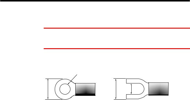
The recommended specifications for wiring terminals are shown below.
Use crimp-on terminals, designed to fit an ISO M3.5 screw, with an insulating sleeve.
|
3.7mm\ |
|
Up to 7mm |
Up to 7mm |
3.7mm |
F3.1.EPS
Fig. 3.1
Table 3.1 Recommended terminals
Maker |
model |
For wire size: |
Tightening torque |
|
|
|
|
|
|
Japan AMP Co., Ltd |
1.25-YS3A |
0.3~1.65mm |
0.8N . m (8 kgf . cm) Up to or Iess |
|
JST Co., Ltd |
YD1.25-3.5 |
|||
|
|
T3.1.EPS
IM 12D11A01-01E |
3-1 |
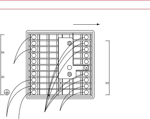
3.1Direction of cable terminals fixing
When wiring cables to terminals on the rear of the instrument, put the cable terminals in the terminal face of the converter in such direction as to draw the cable to left side. (see Fig. 3.2)
 CAUTION
There’s a terminal wiring diagram on the nameplate on the side of the converter.
Put in cable terminals from left side
Terminal name |
|
S1(NC) |
1 |
S1(NO) |
2 |
COM1 |
3 |
S2 |
4 |
S3 |
5 |
S4 |
6 |
COM2 |
7 |
L |
8 |
N |
9 |
|
10 |
|
Terminal name |
11 |
C1 |
12 |
C2 |
13 |
S |
14 |
I1 |
15 |
I 2 |
16 |
|
17 |
T1 |
18 |
T2 |
19 |
mA (1) |
20 |
mA (2) |
|
|
Conductivity |
Analog output |
|
Power |
|
sensor |
cable |
|
Ground |
cable |
|
||
cable |
|
|||
|
cable |
|
Converter rear panel |
|
F3.2.EPS
Fig. 3.2 Direction to put cable terminals
3-2 |
IM 12D11A01-01E |
 Loading...