


ADMAG AXW
Table of contents
 Loading...
User’s
Manual
AXW
Magnetic Flowmeter
Remote Flowtube
IM 01E25D11-01EN
IM 01E25D11-01EN
2nd Edition

i
IM 01E25D11-01EN
AXW
Magnetic Flowmeter
Remote Flowtube
IM 01E25D11-01EN 2nd Edition
2nd Edition: Sep. 2013 (KP)
All Rights Reserved, Copyright © 2012, Yokogawa Electric Corporation
Contents
1. INTRODUCTION ........................................................................................ 1-1
1.1 Using the Magnetic Flowmeter Safely ............................................................ 1-2
1.2 Warranty .............................................................................................................1-3
1.3 Combination Remote Converters ...................................................................1-3
2. HANDLING PRECAUTIONS ..................................................................... 2-1
2.1 Checking Model and Specications ...............................................................2-1
2.2 Storage Precautions .........................................................................................2-1
2.3 Installation Location Precautions ...................................................................2-1
3. INSTALLATION ......................................................................................... 3-1
3.1 Piping Design Precautions ..............................................................................3-1
3.2 Handling Precautions .......................................................................................3-3
3.2.1 General Precautions ..........................................................................3-3
3.2.2 Flowmeter Piping ...............................................................................3-4
3.3 Mounting Procedures .......................................................................................3-4
4. WIRING ...................................................................................................... 4-1
4.1 Wiring the Remote Flowtube ...........................................................................4-1
4.1.1 Wiring Precautions ............................................................................. 4-1
4.1.2 Cables ................................................................................................ 4-2
4.1.3 Wiring Ports .......................................................................................4-3
4.1.4 Wiring Connections ............................................................................4-4
5. MAINTENANCE ......................................................................................... 5-1
5.1 Changing Direction of Electrical Connection ................................................5-1
5.2 Regular Inspection Items ................................................................................. 5-2
5.3 Excitation Coil and Insulation Resistance Check ........................................5-2
5.4 Troubleshooting ................................................................................................5-3
5.4.1 No Indication ......................................................................................5-3
5.4.2 Unstable Zero .................................................................................... 5-4
5.4.3 Disagreement Between Indication and Actual Flow .......................... 5-5
6. OUTLINE .................................................................................................... 6-1
n STANDARD SPECIFICATIONS ........................................................................ 6-1
n STANDARD PERFORMANCE .......................................................................... 6-1
n NORMAL OPERATING CONDITIONS .............................................................. 6-2
n MODEL AND SUFFIX CODE .............................................................................6-3

ii
IM 01E25D11-01EN
n OPTIONAL SPECIFICATIONS .........................................................................6-5
n OPTIONAL SPECIFICATIONS (continued) .....................................................6-6
n DIMENSIONAL DRAWINGS .............................................................................6-7
n SIZING DATA ....................................................................................................6-19
Revision Information ...............................................................................................i
<1. INTRODUCTION>
1-1
IM 01E25D11-01EN
1. INTRODUCTION
This instrument has been adjusted at the factory
before shipment.
To ensure correct use of the instrument, please
read this manual thoroughly and fully understand
how to operate the instrument before operating it.
NOTE
The ADMAG AXW remote owtube is used in
combination with the AXFA11 remote converter.
This manual describes the hardware
conguration of the ADMAG AXW remote
owtube. For details of the AXFA11 remote
converter, see IM 01E20C01-01E instruction
manual.
When setting the parameter “C30” in the remote
converter, select “ADMAG AXF” for ADMAG
AXW remote owtube.
n Regarding This User’s Manual
• This manual should be provided to the end
user.
• Before use, read this manual thoroughly to
comprehend its contents.
• The contents of this manual may be changed
without prior notice.
• All rights are reserved. No part of this manual
may be reproduced in any form without
Yokogawa’s written permission.
• Yokogawa makes no warranty of any kind with
regard to this material, including, but not limited
to, implied warranties of merchantability and
suitability for a particular purpose.
• All reasonable effort has been made to ensure
the accuracy of the contents of this manual.
However, if any errors or omissions are found,
please inform Yokogawa.
• Yokogawa assumes no responsibilities for this
product except as stated in the warranty.
• Please note that this user’s manual may not
be revised for any specication changes,
construction changes or operating part changes
that are not considered to affect function or
performance.
• If the customer or any third party is harmed by
the use of this product, Yokogawa assumes
no responsibility for any such harm owing to
any defects in the product which were not
predictable, or for any indirect damages.
n Safety and Modication Precautions
• The following general safety precautions must
be observed during all phases of operation,
service, and repair of this instrument. Failure
to comply with these precautions or with
specic WARNINGS given elsewhere in
this manual violates safety standards of
design, manufacture, and intended use of the
instrument. Yokogawa assumes no liability for
the customer’s failure to comply with these
requirements. If this instrument is used in
a manner not specied in this manual, the
protection provided by this instrument may be
impaired.
• Yokogawa will not be liable for malfunctions or
damage resulting from any modication made
to this instrument by the customer.
• The following safety symbol marks are used in
this user’s manual and instrument.
WARNING
A WARNING sign denotes a hazard. It calls
attention to procedure, practice, condition or the
like, which, if not correctly performed or adhered
to, could result in injury or death of personnel.
CAUTION
A CAUTION sign denotes a hazard. It calls
attention to procedure, practice, condition or the
like, which, if not correctly performed or adhered
to, could result in damage to or destruction of
part or all of the product.
IMPORTANT
An IMPORTANT sign denotes that attention is
required to avoid damage to the instrument or
system failure.
NOTE
A NOTE sign denotes information necessary
for essential understanding of operation and
features.
<1. INTRODUCTION>
1-2
IM 01E25D11-01EN
Protective grounding terminal
Functional grounding terminal
(This terminal should not be used as a
protective grounding terminal.)
Alternating current
Direct current
1.1 Using the Magnetic
Flowmeter Safely
(1) Installation
WARNING
• Installation of the magnetic owmeter must
be performed by expert engineer or skilled
personnel. No operator shall be permitted to
perform procedures relating to installation.
• The magnetic owmeter must be installed
within the specication conditions.
• The magnetic owmeter is a heavy instrument.
Be careful that no damage is caused to
personnel through accidentally dropping it, or
by exerting excessive force on the magnetic
owmeter. When moving the magnetic
owmeter, always use a trolley, forklift, or crane
and have at least two people carry it.
• When the magnetic owmeter is processing
hot uids, the instrument itself may become
extremely hot. Take sufcient care not to get
burnt.
• Where the uid being processed is a toxic
substance, avoid contact with the uid and
avoid inhaling any residual gas, even after the
instrument has been taken off the piping line for
maintenance and so forth.
• Do not apply excessive weight, for example, a
person stepping on the magnetic owmeter.
• All procedures relating to installation must
comply with the electrical code of the country
where it is used.
(2) Wiring
WARNING
• The wiring of the magnetic owmeter must
be performed by expert engineer or skilled
personnel. No operator shall be permitted to
perform procedures relating to wiring.
• When connecting the wiring, check that
the supply voltage to the converter is within
the range of the voltage specied for this
instrument before connecting the power cable.
In addition, check that no voltage is applied to
the power cable before connecting the wiring.
• The protective grounding must be connected
securely at the terminal with the mark to
avoid danger to personnel.
(3) Operation
WARNING
• When opening the cover, wait for more than 10
minutes after turning off the power. Only expert
engineer or skilled personnel are permitted to
open the cover.
• Do not open the cover in wet weather or humid
environment. When the cover is open, stated
enclosure protection is not applicable.
• Be sure to set parameters as “Protect” on the
write protect function after nish of parameter
setting work.
Under extremely rare case, the infra-red
switches may respond unexpectedly in
such conditions as sticking ball of water or
extraneous substances on the surface of
display panel glass according to the principle of
infra-red switch operation.
Its probability rises in such cases as sticking
rain water by storm or other similar situation
and washing up work near owmeter
installation place.
Either to illuminate or stop illuminating the infra-
red switches by the ashlight may cause the
mis-reaction.
Refer to the manual for converter on how to
use the write protect function in detail.

<1. INTRODUCTION>
1-3
IM 01E25D11-01EN
(4) Maintenance
WARNING
• Maintenance of the magnetic owmeter should
be performed by the trained personnel having
knowledge of safety standard. No operator
shall be permitted to perform any operations
relating to maintenance.
• When opening the cover, wait for more than 10
minutes after turning off the power.
• Do not open the cover in wet weather or humid
environment. When the cover is open, stated
enclosure protection is not applicable.
• Always conform to maintenance procedures
outlined in this manual. If necessary, contact
Yokogawa.
• Care should be taken to prevent the build up
of dirt, dust or other substances on the display
panel glass or data plate. If these surfaces do
get dirty, wipe them clean with a soft dry cloth.
1.2 Warranty
• The terms of this instrument that are
guaranteed are described in the quotation.
We will make any repairs that may become
necessary during the guaranteed term free of
charge.
• Please contact our sales ofce if this instrument
requires repair.
• If the instrument is faulty, contact us with
concrete details about the problem and the
length of time it has been faulty, and state the
model and serial number. We would appreciate
the inclusion of drawings or additional
information.
• The results of our examination will determine
whether the meter will be repaired free of
charge or on an at-cost basis.
n The guarantee will not apply in the
following cases:
• Damage due to negligence or insufcient
maintenance on the part of the customer.
• Problems or damage resulting from handling,
operation or storage that violates the intended
use and specications.
• Problems that result from using or performing
maintenance on the instrument in a location
that does not comply with the installation
location specied by Yokogawa.
• Problems or damage resulting from repairs or
modications not performed by Yokogawa or
someone authorized by Yokogawa.
• Problems or damage resulting from
inappropriate reinstallation after delivery.
• Problems or damage resulting from disasters
such as res, earthquakes, storms, oods, or
lightning strikes and external causes.
n Trademarks:
ADMAG and AXW are registered trademarks of
Yokogawa Electric Corporation.
Company names and product names used
in this material are registered trademarks or
trademarks of their respective owners.
1.3 Combination Remote
Converters
IMPORTANT
• The AXW remote owtube (size 500 (20
in.) to 1800 mm (72 in.)) should be used in
combination with AXFA11 remote converter.
Contact Yokogawa before using it in
combination with converters other than
AXFA11.

Blank Page

<2. HANDLING PRECAUTIONS>
2-1
IM 01E25D11-01EN
2. HANDLING PRECAUTIONS
This instrument has been inspected carefully at
the factory before shipment. When the instrument
is delivered, visually check that no damage has
occurred during transportation.
Read this section carefully as it contains important
information on handling this instrument. Refer to
the relevant sections for information not contained
in this section. If you have any problems or
questions, please contact Yokogawa sales ofce.
2.1 Checking Model and
Specications
The model code and specications are found on
the data plate located on the outside of the case.
Check that the model code and specications
match what you have ordered.
Be sure you have your model number and serial
number available when contacting Yokogawa.
F0201.ai
KCC-
REM-
YHQ-
EEN
165
Figure 2.1.1 Data Plate
2.2 Storage Precautions
If the instrument is to be stored for a long period of
time after delivery, observe the following points.
The instrument should be stored in its original
packing condition in the storage location.
Select a storage location that fulls the following
conditions:
• A place where it will not be exposed to rain or
water
• A place subject to minimal vibrations or
shocks
• Temperature and humidity levels should be
as follows:
Temperature: -10 to 70°C
Humidity: 5 to 80% RH (no condensation)
The preferred ambient temperature
and humidity levels are 25°C and
approximately 65% RH.
If the magnetic owmeter is transferred to
the installation site and stored without being
installed, its performance may be impaired due
to the inltration of rainwater and so forth. Be
sure to install and wire the magnetic owmeter
as soon as possible after transferring it to the
installation location.
2.3 Installation Location
Precautions
Select the installation location with consideration
to the following items to ensure long-term stable
operation of the instrument.
n Ambient Temperature:
Avoid installing the instrument in locations
with constantly uctuating temperatures. If the
location is subject to radiant heat from the plant,
provide heat insulation or improve ventilation.
n Atmospheric Condition:
Avoid installing the instrument in a corrosive
atmosphere. In situations where this is
unavoidable, consider ways to improve
ventilation and to prevent rainwater from
entering and being retained in the conduit
pipes.
n Vibrations or Shocks:
Avoid installing the instrument in a place subject
to shocks or vibrations.

Blank Page

<3. INSTALLATION>
3-1
IM 01E25D11-01EN
3. INSTALLATION
WARNING
Installation of the magnetic owmeter must
be performed by expert engineer or skilled
personnel. No operator shall be permitted to
perform procedures relating to installation.
3.1 Piping Design Precautions
IMPORTANT
Design piping correctly, referring to the following
to prevent damage to owtubes and to assure
accurate measuring.
(1) Location
IMPORTANT
Install the owmeter in a location where it is
not exposed to direct sunlight. The minimum
ambient temperature is limited by the minimum
uid temperature of the owtube (the lining). For
more information, refer to Chapter 6 “OUTLINE”.
The owmeter may be used in an ambient
humidity where the relative humidity ranges from
0 to 100%. However, avoid long-term continuous
operation at relative humidity above 95%.
(2) Noise Avoidance
IMPORTANT
The owmeter should be installed away from
electrical motors, transformers, and other power
sources in order to avoid interference with
measurement.
(3) Required Lengths of Straight Runss
To maintain accurate measurement, see JIS B7554
“Electro Magnetic Flowmeters” which explains the
requirements for upstream piping conditions of
magnetic owmeters.
Based on JIS B7554 “Electro Magnetic Flowmeters”
and our piping condition test data, we recommend
the piping conditions as shown in the following
gures.
When installing two or more magnetic owmeters
on a single pipe, provide a run of at least 10D
between them.
F0301.ai
D: Flowtube Size
Gate valve
fully open
5D or more
2D
or more
Reducer
pipe
Expander
pipe
0 is allowable. 0 is allowable.
10D or more
10D or more
Tee
90-degree bent
Various valves
0 is allowable.5D or more 0 is allowable.5D or more
2D
or more
2D
or more
Figure 3.1.1 Required Lengths of Straight Runs
*1: Do not install anything in the vicinity that may
interfere with the magnetic eld, induced signal
voltages, or ow velocity distributions of the
owmeter.
*2: A straight run may not be required on the
downstream side of the owmeter. However,
if a downstream valve or other tting causes
irregularity or deviation in ows, provide a
straight run of 2D to 3D on the downstream
side.
*3: The valves shall be mounted on the
downstream side so that deviated ows do not
occur in the owtube and to avoid startup from
an empty condition.
(4) Maintaining Stable Fluid Conductivity
IMPORTANT
Do not install the owmeter where uid
conductivity tends to become uneven. If
chemicals are fed near the upstream side of a
magnetic owmeter, they may affect the ow
rate’s indications. To avoid this situation, it is
recommended that the chemical feed ports be
located on the downstream side of the owmeter.
If it is unavoidable that chemicals must be fed on
the upstream side, provide a sufcient length of
straight run (approximately 50D) to ensure the
proper mixture of uids.
F0302.ai
(Incorrect)
Upstream side
(Correct)
Downstream side
Figure 3.1.2 Chemical Injection
<3. INSTALLATION>
3-2
IM 01E25D11-01EN
(5) Precautions for Use of Liquid Sealing
Compounds
IMPORTANT
Care must be taken in using liquid sealing
compounds on the piping, as it may have a
negative inuence on the ow indications by
owing out and covering the surfaces of an
electrode or grounding ring. In particular, care
must be taken if a liquid sealing compound is
used in the case of vertical piping.
(6) Service Area
Select locations where there is adequate space to
service installing, wiring, overhauling, etc
(7) Bypass Line
It is recommended to install a bypass line to facilitate
maintenance and zero adjustment.
Bypass valve
Block valve
Block valve
F0303.ai
Figure 3.1.3 Bypass Line
(8) Supporting the Flowmeter
CAUTION
Do not secure the owmeter separately to
prevent the vibrations, shocks, and expansion
and contraction forces of the piping from
affecting it. Fix the pipeline or its anges rst,
then let them support the owmeter.
For vertical, mounting, make sure that the weight
of piping does not weigh on the owmeter.
To release the load from tightening the owmeter
to the pipeline, set a expansive pipe in the
downstream side.
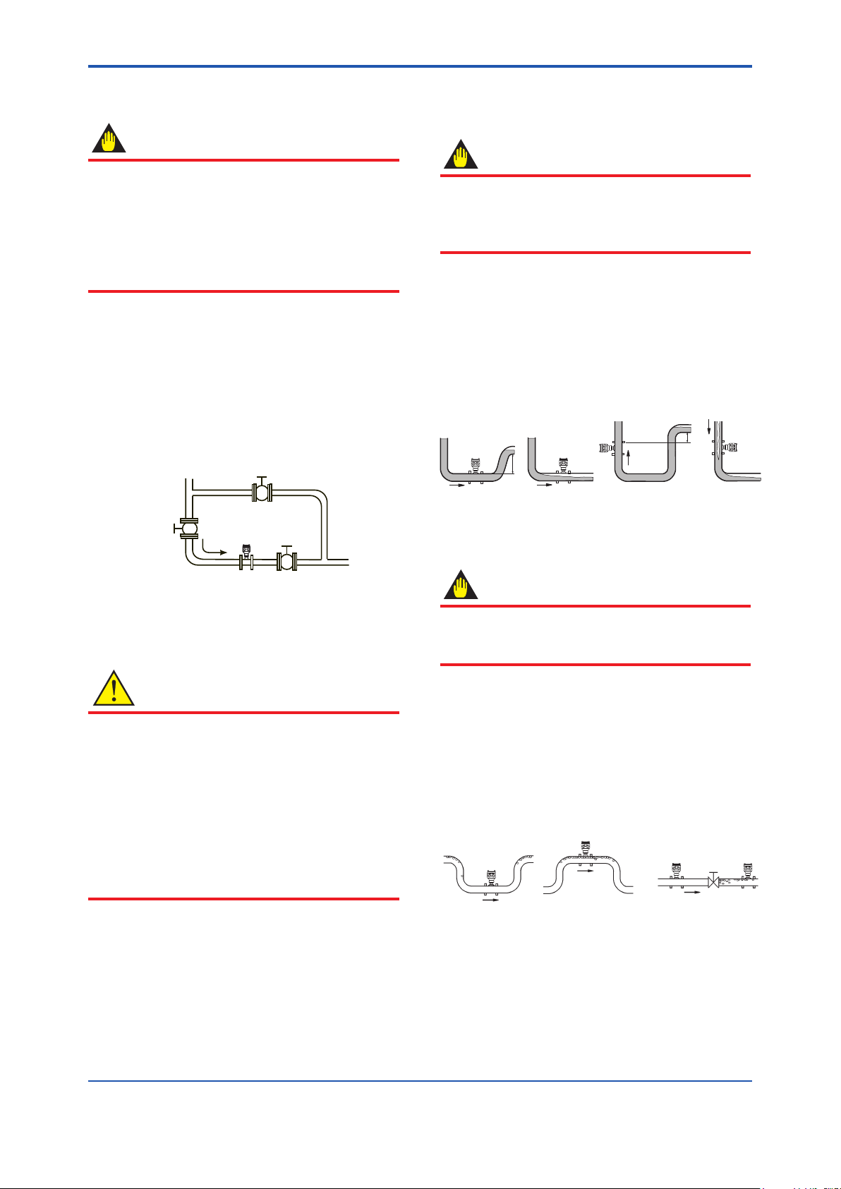
(9) Mounting Positions
• Pipes must be fully lled with liquids.
IMPORTANT
It is essential that pipes remain fully lled at
all times, otherwise ow rate indications may
be affected and measurement errors may be
caused.
Piping shall be designed so as to maintain the
interior of the owtube lled with uids.
Vertical mounting is effective in such cases as
when uids tend to separate or solid matter may be
precipitated. When employing vertical mounting,
direct the uids from the bottom to the top to ensure
that the pipes remain fully lled.
h
h>0
h>0
h
F0304.ai
(Incorrect)
(Correct)
(Incorrect)
(Correct)
Figure 3.1.4 Mounting Positions
• Avoid air bubbles.
IMPORTANT
If air bubbles enter a measurement pipe,
ow rate indications may be affected and
measurement errors may be caused.
In cases where uids contain air bubbles, piping must
be designed to prevent them from accumulating in
the measurement pipe of a owtube.
If a valve exists near the owmeter, try to mount the
owmeter on the valve’s upstream side in order to
prevent a possible reduction of pressure inside the
pipe, thereby avoiding the possibility of air bubbles.
F0305.ai
Valve
(Incorrect)
(Correct)
(Incorrect)
(Correct)
Figure 3.1.5 Avoiding Air Bubbles
<3. INSTALLATION>
3-3
IM 01E25D11-01EN
• Mounting orientation
IMPORTANT
If electrodes are perpendicular to the ground, air
bubbles near the top or precipitates at the bottom
may cause measurement errors. Ensure that the
terminal box of a remote owtube is mounted
above the piping to prevent water from entering
them.
F0306.ai
Correct
Incorrect
Electrode
Air bubble
Precipitate
Electrode
Incorrect
Water can
seep into
the terminal
box.
Figure 3.1.6 Mounting Orientation
3.2 Handling Precautions
WARNING
The magnetic owmeter is a heavy instrument.
Be careful that no damage is caused to
personnel through accidentally dropping it, or
by exerting excessive force on the magnetic
owmeter. When moving the magnetic
owmeter, always use a trolley, forklift, or crane
and have at least two people carry it.
3.2.1 General Precautions
(1) Precaution during Transportation
The magnetic owmeter is packed tightly. When
it is unpacked, pay attention to prevent damaging
the owmeter. To prevent accidents while it is being
transported to the installing location, transport it to
the site in its original packing.
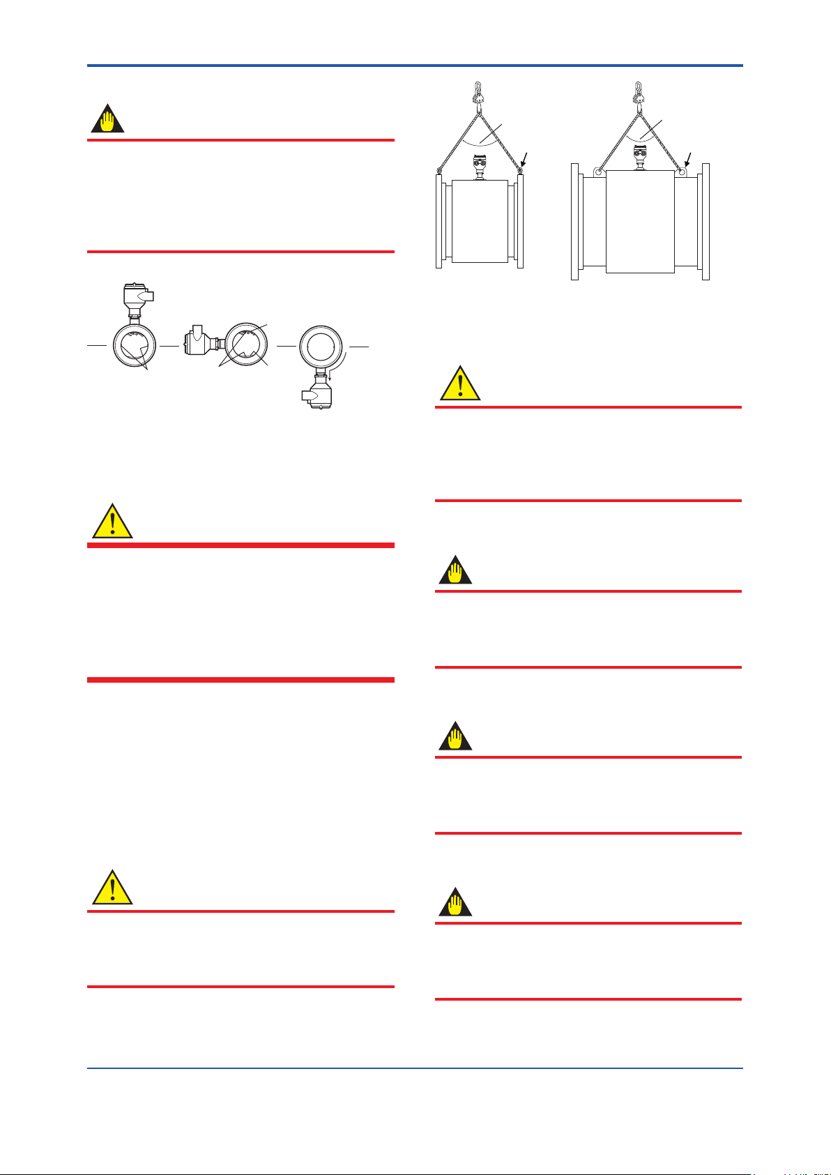
CAUTION
When lifting the owtube, use the lifting rings
(eye bolts or eye plates) as in Figure 3.2.1.
Never lift it using a bar passed through the
owtube as this damages the liner severely.
F0307.ai
90 degrees or less
90 degrees or less
Eye bolt Eye plate
Figure 3.2.1 Lifting Flowtube
(2) Avoiding Shocks from Impact
CAUTION
Care should be taken not to drop the owmeter
or expose it to excessive shock. In particular, be
careful not to subject the ange surface to shock.
This may lead to liner damage which will result in
inaccurate readings.
(3) Flange Protection Covers
IMPORTANT
Keep the protective covering (i.e. the corrugated
cardboard or other cushioning material) in place
over the ange except when mounting the
owmeter to the pipe.
(4) Terminal Box Cover
IMPORTANT
As it is possible that the insulation will
deteriorate, do not remove the wrapping of the
terminal box nor open the terminal box cover
until it is time to wire it.
(5) Long-term Non-use
IMPORTANT
It is not desirable to leave the owmeter unused
for a long term after installation. If this situation
is unavoidable, take care of the owmeter by
observing the following.
<3.INSTALLATION>
3-4
IM 01E25D11-01EN
• Conrmationofsealingconditionsforthe
owmeter
Conrm that the terminal box screw and wiring ports
are well sealed. Equip the conduit piping with drain
plugs or waterproof glands to prevent moisture or
water from penetrating into the owmeter through
the conduit.
• Regularinspections
Inspect the sealing conditions as mentioned above,
and the inside of the terminal box at least once a
year. Also, due to rain, etc. when it is suspected
that water may have penetrated into the inside
owmeter perform supplementary inspections.
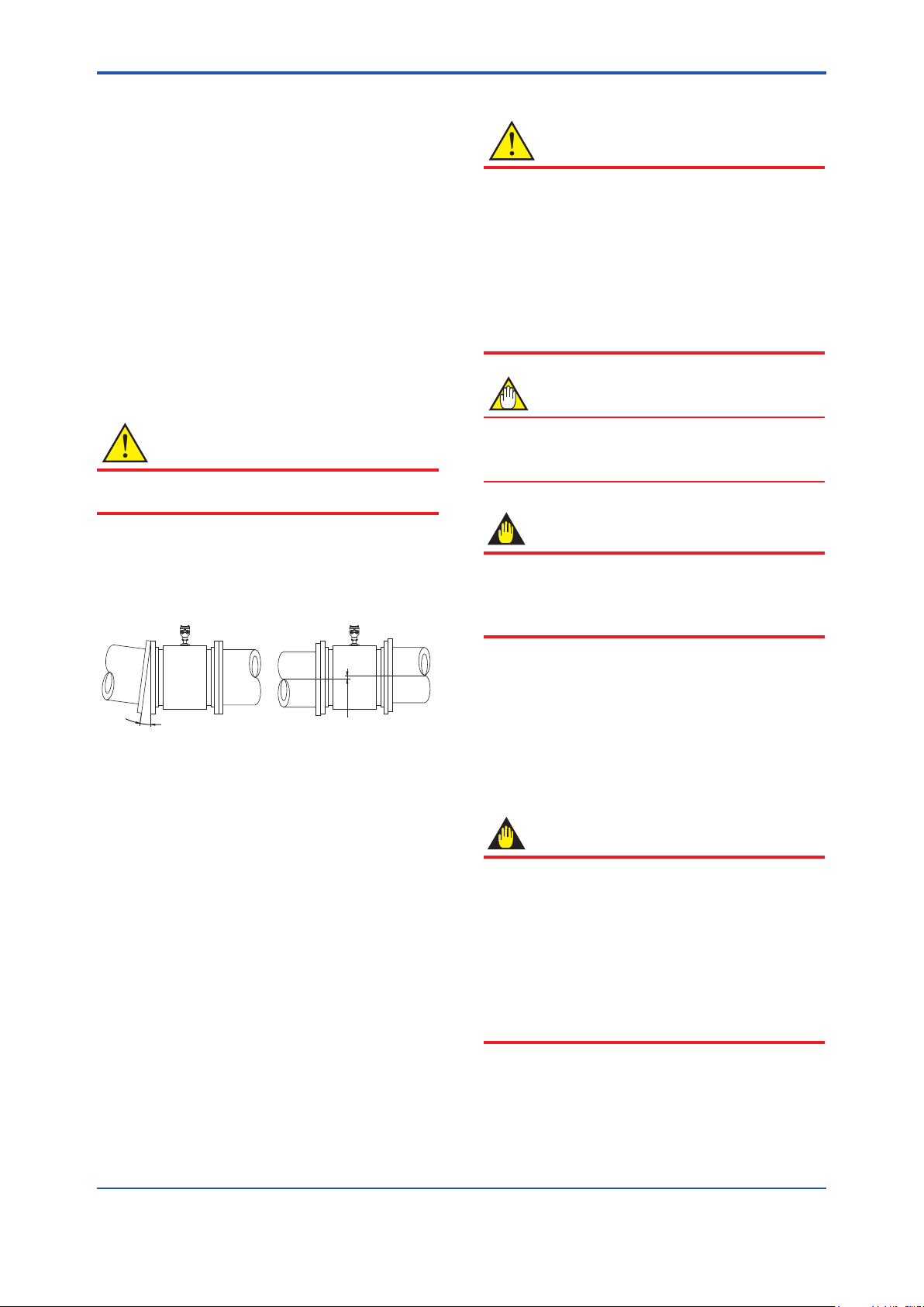
3.2.2 FlowmeterPiping
CAUTION
Misaligned or slanted piping can lead to leakage
and damage to the anges.
(1) Correct any misaligned or slanted piping, and
any gaps that may exist between mounting
anges before installing the owmeter (refer to
Figure 3.2.2).
Slanted
F0308.ai
Misaligned
Figure3.2.2 SlantedandMisalignedFlowmeter
Piping
(2) Inside a newly installed pipeline, there may
be some foreign substances such as residue
from welding or wood chips. Remove them
by ushing the piping before mounting the
owmeter. This prevents the lining from
being damaged, as well as the occurrence
of erroneous measured signals resulting
from foreign substances passing through the
owtube during measurement.
3.3 MountingProcedures
CAUTION
When attaching optional grounding rings to
the owtube with lining material natural hard
rubber or uorocarbon PTFE, gaskets must be
placed between each grounding ring and the
owtube. Fluid leakage will happen without these
gaskets. These gaskets are to be supplied by
customer. Do not forget those gaskets also when
ordering and attaching the grounding rings later
additionally.
NOTE
The tightening torque value varies depending
on the type of lining and gasket as shown in the
tables in this section.
IMPORTANT
Use bolts and nuts in compliance with the ange
ratings. When choosing the gaskets, be sure to
choose sheet gaskets designed to t for ange
standard.
(1) MountingDirection
Mount the owmeter so that the ow direction of
the uid to be measured is in line with the direction
of the arrow mark on the owmeter. It may be
especially difcult to move large size owtubes after
bringing them into the pit. Check directions before
bringing.
IMPORTANT
If it is impossible to match the direction of
the arrow mark, the direction of the electrical
connection can be changed. Refer to Section 5.1
to do this properly.
In case the uid being measured ows against
the arrow direction, refer to the parameter J20:
FlowDirection in the user’s manual of the
AXFA11 Magnetic Flowmeter Remote Converter
(IM 01E20C01-01E).
<3. INSTALLATION>
3-5
IM 01E25D11-01EN
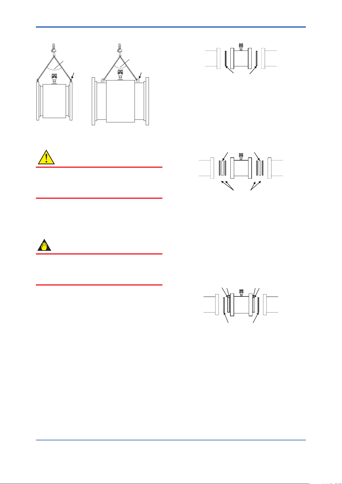
(2) Carrying Flowtube
F0309.ai
90 degrees or less
90 degrees or less
Eye bolt
Eye plate
Figure 3.3.1 Carrying Flowtube
CAUTION
• When carrying the owtube, use the lifting
rings (eye bolts or eye plates).
• To assure safety, keep lifting angle less than
90 degrees as shown in Figure 3.3.1
(3) Positioning Flowtube
Bring in the owtube, place it and use a jack to
adjust its position.
IMPORTANT
Apply the jack to the anges of the owtube.
In addition, adjust any misalignment when the
owtube is brought in, as the jack can adjust
vertical position, but not horizontal one.
(4) Applying Gasket and optional Grounding
Rings
Gasket:
Necessary gaskets for piping connection are
as below depending on the choice of grounding
rings.
Use sheet gaskets designed to t for ange
standard. The GF type-1 gaskets by JIS G
3443-2 should be used for the JIS F12 ange
models in sizes 1100 mm (44 in.) and above. In
this case, the gasket groove is required on the
customer pipe anges.
The thickness of gasket should be 2mm
(0.08in.) to 5mm (0.2in.) for sizes up to 1000
mm (40 in.), and 5 mm (0.2 in.) or more
for larger sizes. The type of gasket should
be a kind of soft rubber, or its equivalent in
hardness.
1. Standard (no grounding rings)
Gaskets A supplied by customer
Customer
pipe
Customer
pipe
A A
F0310.ai
Figure 3.3.2 Installation without Grounding
Rings
When using the GF type-1 gaskets, the
gasket groove is required as mentioned
above.
2. With optional grounding rings (code GR1)
Optional grounding rings
Gaskets A and B supplied by customer
Customer
pipe
Customer
pipe
A
B
B
A
F0311.ai
Figure 3.3.3 Installation with Grounding Rings
GR1
It is recommended to use the same gasket
for A and B. Both gaskets A and B are to be
supplied by customer.
When polyurethane or natural soft rubber
lining, the gaskets B are not necessary.
3. With optional grounding rings (code GR2)
Customer
pipe
Optional grounding rings
with integrated gaskets B included
Gaskets A supplied by customer
Customer
pipe
F0312.ai
A A
B
B
Figure 3.3.4 Installation with Grounding Rings
GR2
This is available for the models with
process connection JIS F12 (JIS 75M) in
sizes 1100 mm (44 in.) and above. Only
gaskets A are to be supplied by customer.
The grounding rings are installed and
locked onto the owtube with gaskets B
when shipped from factory.
Mounting Procedure (no Grounding Rings):
Connect the owtube’s ange and the
customer’s pipe which contact process uid by
some wire supplied by customer.
<3. INSTALLATION>
3-6
IM 01E25D11-01EN
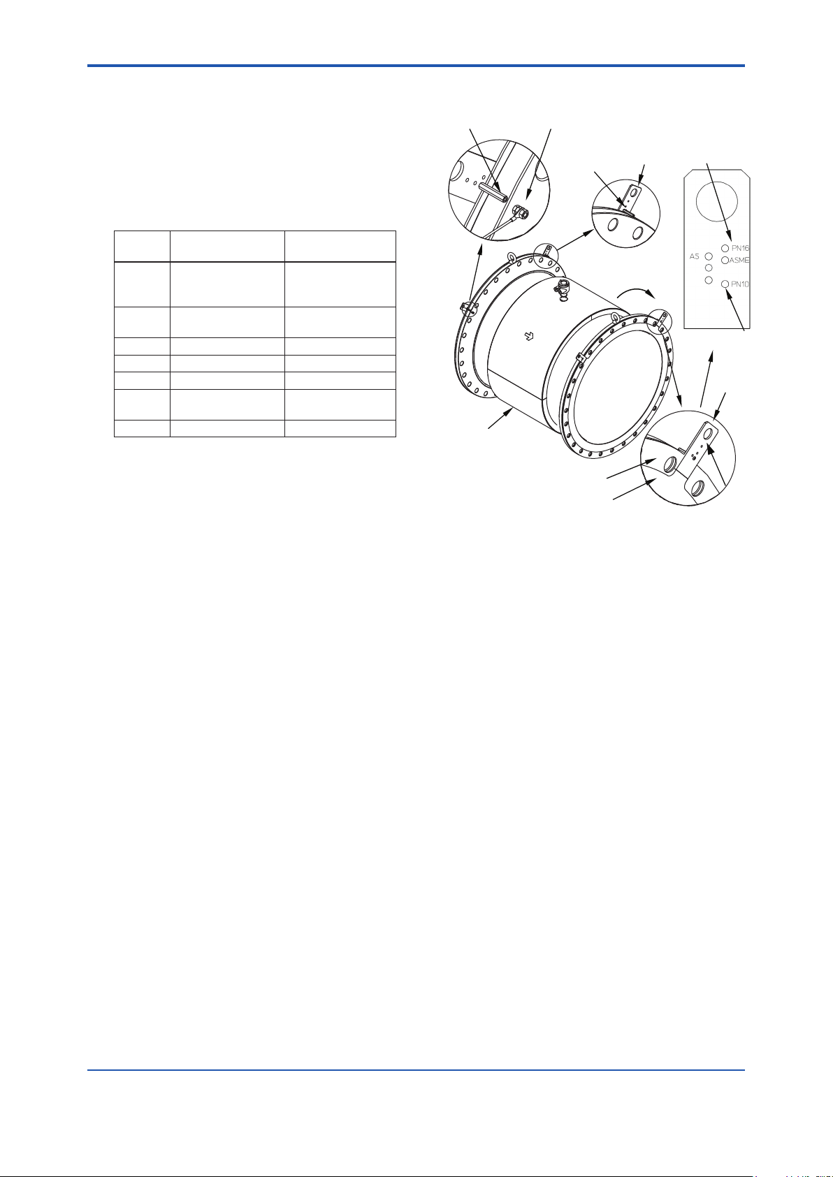
Mounting Procedure (with optional
Grounding Rings GR1 for sizes up to
1000 mm (40 in.)):
1. Handles of the grounding ring have some
holes which correspond to outer diameter
of each ange type. There are printings
near each hole. The printings show types
of ange. See the table below.
Printing
Process
Connection Code
Flange Standard
ASME -CA1
ASME B16.5
Class 150, ASME
B16.47 Class 150
AWWA -CB1
AWWA C207
Class D
PN10 -CE1 EN1092-1 PN10
PN16 -CE2 EN1092-1 PN16
10K -CJ1 JIS B2220 10K
AS -CS1, -CS2, -CT1
AS2129 table D, E
AS4087 PN16
F12 -CG1 JIS F12 (JIS 75M)
2. Conrm the centering pin is xed to the
hole corresponding to ange or x the
centering pin to the correct hole.
3. Hang the grounding rings with their
ange type printings outer side of the
owtube. Set the angle of both handles
symmetrically to be 45 degree from top. If
there are any bolt-holes under the handles,
turn the grounding rings clockwise in order
to locate handles between bolt-holes.
Center the grounding ring to the center of
the owtube.
4. Connect the wire from the grounding ring
to the screw of the owtube’s ange and x
the wire by the nut. This procedure (item 1
to 4) must be done for the both sides of the
owtube.
5. Install the owtube into the customer’s pipe
with the gaskets A.
F0313.ai
Handle
Screw & Nut : Connect the wire from the
grounding ring or the customer’s pipe
Clockwise
Gasket B
Grounding Ring
Handle
Printed
Surface
Hole
Printing of
Flange Type
Flowtube
Centering Pin
Centering Pin
F12
10K
Note : Gasket A and B are also placed concentrically with
the owtube.
Figure 3.3.5 Mounting Procedure with Grounding
Rings GR1 for sizes up to 1000 mm
(40 in.)
Mounting Procedure (with optional
Grounding Rings GR1 for sizes 1100mm (44
in.)) and above :
1. The grounding ring is temporarily xed
onto the owtube by four bolts. Hang the
grounding ring up using a crane or a hoist
so that it would not fall down from the
owtube while setting the gasket B.
2. Unfasten the bolts and remove the
grounding ring off from the owtube.
3. Place the gasket B to the owtube. Cut out
holes on the gasket B if necessary, so that
the bolts can go through. Fix the grounding
ring to the owtube by the four bolts again.
4. Connect the wire from the grounding ring
to the screw at the owtube ange and x
the wire by the nut. This procedure (item 1
to 4) must be done for the both sides of the
owtube.
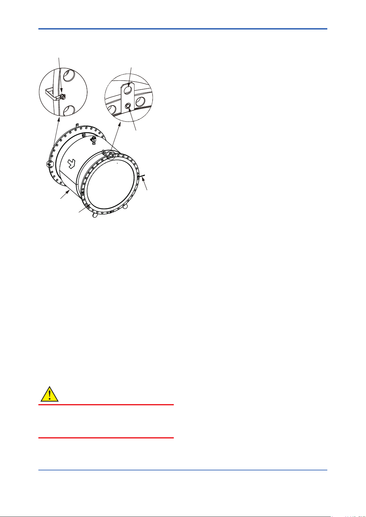
<3. INSTALLATION>
3-7
IM 01E25D11-01EN
5. Install the owtube into the customer’s pipe
with the gaskets A.
F0314.ai
Hang the grounding
ring up with this point.
Unfasten the bolts and
remove the grounding rings.
Cut out some holes on the
gasket B when necessary.
Wire
Grounding Ring
Flowtube
Screw & Nut : Connect the wire from the
grounding ring or the customer’s pipe.
Note : Gasket A and B should be placed concentrically with
the owtube.
Figure 3.3.6 Mounting Procedure with Grounding
Rings GR1 for sizes 1100 mm (44 in.)
and above
Mounting Procedure (with optional
Grounding Rings GR2):
The grounding rings are installed and locked
onto the owtube with gaskets B when shipped
from factory. Install the owtube into the
customer’s pipe with gaskets A supplied by
customer.
(5) Tightening Nuts
Pass the bolts from pipe line side, not owtube side,
and tighten the bolts according to the torque values
for the metal piping in Table 3.3.1 or 3.3.2
CAUTION
• Be sure to tighten the nuts according to the
prescribed toeque values. Tighten them
diagonally with the same torque values, step
by up to the prescribed torque value.
Loading...