


 Loading...
User’s
Manual |
Model DO402G [Style: S3] |
|
|
|
|
|
|
||
|
Dissolved Oxygen Converter |
|
|
|
IM 12J05D02-01E
IM 12J05D02-01E
8th Edition

PREFACE
 WARNING
Electric discharge
The EXA analyzer contains devices that can be damaged by electrostatic discharge. When servicing this equipment, please observe proper procedures to prevent such damage. Replacement components should be shipped in conductive packaging. Repair work should be done at grounded workstations using grounded soldering irons and wrist straps to avoid electrostatic discharge.
Installation and wiring
The EXA analyzer should only be used with equipment that meets the relevant IEC, American or Canadian standards. Yokogawa accepts no responsibility for the misuse of this unit.
 CAUTION
The Instrument is packed carefully with shock absorbing materials, nevertheless, the instrument may be damaged or broken if subjected to strong shock, such as if the instrument is dropped. Handle with care.
Although the instrument has a weatherproof construction, the transmitter can be harmed if it becomes submerged in water or becomes excessively wet.
Do not use an abrasive or solvent in cleaning the instrument.
Notice
•This manual should be passed on to the end user.
•The contents of this manual are subject to change without prior notice.
•The contents of this manual shall not be reproduced or copied, in part or in whole, without permission.
•This manual explains the functions contained in this product, but does not warrant that they are suitable the particular purpose of the user.
•Every effort has been made to ensure accuracy in the preparation of this manual.
However, when you realize mistaken expressions or omissions, please contact the nearest Yokogawa Electric representative or sales office.
•This manual does not cover the special specifications. This manual may be left unchanged on any change of specification, construction or parts when the change does not affect the functions or performance of the product.
•If the product is not used in a manner specified in this manual, the safety of this product may be impaired.
Yokogawa is not responsible for damage to the instrument, poor performance of the instrument or losses resulting from such, if the problems are caused by:
•Improper operation by the user.
•Use of the instrument in improper applications
•Use of the instrument in an improper environment or improper utility program
•Repair or modification of the related instrument by an engineer not authorized by Yokogawa.
Safety and Modification Precautions
•Follow the safety precautions in this manual when using the product to ensure protection and safety of the human body, the product and the system containing the product.
The following safety symbols are used on the product as well as in this manual.
 DANGER
This symbol indicates that an operator must follow the instructions laid out in this manual in order to avoid the risks, for the human body, of injury, electric shock, or fatalities. The manual describes what special care the operator must take to avoid such risks.
IM 12J05D02-01E

 WARNING
This symbol indicates that the operator must refer to the instructions in this manual in order to prevent the instrument (hardware) or software from being damaged, or a system failure from occurring.
 CAUTION
This symbol gives information essential for understanding the operations and functions.
This symbol indicates Protective Ground Terminal
This symbol indicates Function Ground Terminal (Do not use this terminal as the protective ground terminal.)
This symbol indicates Alternating current.
This symbol indicates Direct current.
Warranty and service
Yokogawa products and parts are guaranteed free from defects in workmanship and material under normal use and service for a period of (typically) 12 months from the date of shipment from the manufacturer. Individual sales organizations can deviate from the typical warranty period, and the conditions of sale relating to the original purchase order should be consulted. Damage caused by wear and tear, inadequate maintenance, corrosion, or by the effects of chemical processes are excluded from this warranty coverage.
In the event of warranty claim, the defective goods should be sent (freight paid) to the service department of the relevant sales organization for repair or replacement (at Yokogawa discretion). The following information must be included in the letter accompanying the returned goods:
•Part number, model code and serial number
•Original purchase order and date
•Length of time in service and a description of the process
•Description of the fault, and the circumstances of failure
•Process/environmental conditions that may be related to the installation failure of the device
•A statement whether warranty or non-warranty service is requested
•Complete shipping and billing instructions for return of material, plus the name and phone number of a contact person who can be reached for further information.
Returned goods that have been in contact with process fluids must be decontaminated/disinfected before shipment. Goods should carry a certificate to this effect, for the health and safety of our employees. Material safety data sheets should also be included for all components of the processes to which the equipment has been exposed.
How to dispose the batteries:
This is an explanation about the new EU Battery Directive (DIRECTIVE 2006/66/EC). This directive is only valid in the EU. Batteries are included in this product. Batteries incorporated into this product cannot be removed by yourself. Dispose them together with this product. When you dispose this product in the
EU, contact your local Yokogawa Europe B.V.office. Do not dispose them as domestic household waste. Battery type: silver oxide battery
Notice:
The symbol (see above) means they shall be sorted out
and collected as ordained in ANNEX II in DIRECTIVE 2006/66/EC.
IM 12J05D02-01E
|
TABLE OF CONTENTS |
|
PREFACE..................................................................................................................... |
1 |
|
1. Introduction And General Description.............................................................. |
1-1 |
|
1-1. |
Instrument Check............................................................................................ |
1-1 |
1-2. Application....................................................................................................... |
1-2 |
|
1-3. |
General information......................................................................................... |
1-3 |
1-4. |
Configuration checklist for DO402................................................................... |
1-5 |
1-5. |
System Configuration...................................................................................... |
1-6 |
1-5-1. Dissolved Oxygen Sensor................................................................................................ |
1-6 |
|
1-5-2. The holders...................................................................................................................... |
1-7 |
|
2. DO402G SPECIFICATIONS................................................................................. |
2-1 |
|
2-1. |
General............................................................................................................ |
2-1 |
2-2. |
Operating specifications.................................................................................. |
2-2 |
2-3. |
Model and suffix codes.................................................................................... |
2-3 |
3. Installation And Wiring....................................................................................... |
3-1 |
3-1. Installation and dimensions............................................................................. |
3-1 |
3-1-1. Installation site.................................................................................................................. |
3-1 |
3-1-2. Mounting methods............................................................................................................ |
3-1 |
3-2. Wiring.............................................................................................................. |
3-3 |
3-2-1. Wiring of DO30G.............................................................................................................. |
3-3 |
3-2-2. Wiring of DO70G.............................................................................................................. |
3-3 |
3-2-3. Preparation................................................................................................... |
3-4 |
3-3. Wiring the power supply.................................................................................. |
3-5 |
3-3-1. General precautions......................................................................................................... |
3-5 |
3-3-2. Access to terminal and cable entry.................................................................................. |
3-6 |
3-3-3. AC power.......................................................................................................................... |
3-7 |
3-3-4. Grounding the housing..................................................................................................... |
3-7 |
3-3-5. Switching on the instrument............................................................................................. |
3-7 |
3-4. Wiring the contact signals............................................................................... |
3-8 |
3-4-1. General precautions......................................................................................................... |
3-8 |
3-4-2. Contact outputs................................................................................................................ |
3-8 |
3-4-3. Contact input.................................................................................................................... |
3-8 |
3-5. Wiring the analog output signals..................................................................... |
3-9 |
3-5-1. General precautions......................................................................................................... |
3-9 |
3-5-2. Analog output signals....................................................................................................... |
3-9 |
3-6. Wiring the standard galvanic sensor.............................................................. |
3-9 |
3-7. Wiring other galvanic sensors....................................................................... |
3-10 |
3-8. Wiring the standard optical sensor (DO70G)................................................ |
3-10 |
3-9. Wiring polarographic sensors......................................................................... |
3-11 |
3-10. Wiring RS485 signal..................................................................................... |
3-11 |
4. Operation; Display Functions And Setting....................................................... |
4-1 |
|
4-1. |
Operator interface........................................................................................... |
4-1 |
4-2. |
Explanation of operating keys......................................................................... |
4-2 |
4-3. |
Setting passcodes........................................................................................... |
4-3 |
4-4. |
Display functions (default)............................................................................... |
4-4 |
5. Parameter setting................................................................................................ |
5-1 |
5-1. Maintenance mode.......................................................................................... |
5-1 |
5-1-1. Manual activation of Hold................................................................................................. |
5-2 |
IM 12J05D02-01E
8th Edition: Feb. 2014(YK)
All Rights Reserved, Copyright © 2003, Yokogawa Electric Corporation
IM 12J05D02-01E
5-1-2. Manual Wash start/stop................................................................................................... |
5-3 |
5-1-3. Setpoint adjustment.......................................................................................................... |
5-4 |
5-2. Commissioning mode...................................................................................... |
5-5 |
5-2-1. Setpoints.......................................................................................................................... |
5-6 |
5-2-2. Range............................................................................................................................... |
5-8 |
5-2-3. Hold ............................................................................................................................... |
5-10 |
5-2-4. Wash ............................................................................................................................. |
5-12 |
5-2-5. Service........................................................................................................................... |
5-13 |
5-3. Notes for guidance in the use of service coded settings............................... |
5-14 |
5-3-1. Parameter specific functions.......................................................................................... |
5-14 |
5-3-2. Temperature functions................................................................................................... |
5-16 |
5-3-3. Calibration functions....................................................................................................... |
5-16 |
5-3-4. mA output settings......................................................................................................... |
5-18 |
5-3-5. Contact outputs.............................................................................................................. |
5-20 |
5-3-6. User interface................................................................................................................. |
5-26 |
5-3-7. Communication setup..................................................................................................... |
5-28 |
5-3-8. General .......................................................................................................................... |
5-28 |
5-3-9. Test and setup mode .................................................................................................... |
5-28 |
6. CALIBRATION PROCEDURE.............................................................................. |
6-1 |
6-1. General............................................................................................................ |
6-1 |
6-1-1. Calibration methods......................................................................................................... |
6-1 |
6-1-2. Diagnostic functions performed during calibration........................................................... |
6-2 |
6-2. Calibration procedure using air calibration method......................................... |
6-2 |
6-2-1. Preparation....................................................................................................................... |
6-2 |
6-2-2. Procedure for air calibration............................................................................................. |
6-3 |
6-3. Calibration procedure using water calibration method.................................... |
6-4 |
6-3-1. Preparation....................................................................................................................... |
6-4 |
6-3-2. Calibration operation (water calibration method)............................................................. |
6-4 |
6-3-3. Procedure for Water calibration....................................................................................... |
6-5 |
6-4. Calibration method using manual calibration method..................................... |
6-6 |
6-4-1. Preparation....................................................................................................................... |
6-6 |
6-4-2. Procedure for manual calibration..................................................................................... |
6-7 |
7. Maintenance........................................................................................................ |
7-1 |
7-1. Overall dissolved oxygen metering system..................................................... |
7-1 |
7-1-1. Inspection and maintenance to be implemented periodically.......................................... |
7-1 |
7-1-2. Inspection and maintenance to be implemented on occasion......................................... |
7-1 |
7-2. Periodic maintenance for the EXA DO402G converter................................... |
7-2 |
7-3. Fuse Replacement.......................................................................................... |
7-2 |
8. Troubleshooting.................................................................................................. |
8-1 |
8-1. Measures in the case of converter operation failure....................................... |
8-1 |
8-1-1. No dissolved-oxygen converter operation........................................................................ |
8-1 |
8-1-2. Operation key or display failure....................................................................................... |
8-1 |
8-2. Measures in the case of failure (Error) detection............................................ |
8-2 |
9. Spare Parts.......................................................................................................... |
9-1 |
10. Appendix ......................................................................................................... |
10-1 |
10-1. Setpoint....................................................................................................... |
10-1 |
10-2. Range.......................................................................................................... |
10-1 |
10-3. Hold............................................................................................................. |
10-1 |
10-4. Wash........................................................................................................... |
10-1 |
10-5. User setting table........................................................................................ |
10-2 |
IM 12J05D02-01E
11. Appendix 2 QUALITY INSPECTION................................................................ |
11-1 |
Customer Maintenance Parts List (for Style: S3) .................. |
CMPL 12J05D02-03E |
Revision Record .......................................................................................................... |
i |
IM 12J05D02-01E
Introduction 1-1
1. Introduction And General Description
The Yokogawa EXA is a 4-wire coverter designed for industrial process monitoring, measurement and control applications. This instruction manual contains the information needed to install, set up, operate and maintain the unit correctly. This manual also includes a basic troubleshooting guide to answer typical user questions.
Yokogawa can not be responsible for the performance of the EXA analyzer if these instructions are not followed.
1-1. Instrument Check
Upon delivery, unpack the instrument carefully and inspect it to ensure that it was not damaged during shipment. If damage is found, retain the original packing materials (including the outer box) and then immediately notify the carrier and the relevant Yokogawa sales office.
Make sure the model number on the textplate affixed to the top of the display board of the instrument agrees with your order.
 WARNING
The textplate will also contain the serial number and power supply selection.
Be sure to apply correct power to the unit.
MODEL |
DO402G |
SUPPLY |
115VAC 50/60Hz MAX.10VA |
SUFFIX |
|
OUTPUT |
0-20mADC or 4-20mADC |
STYLE |
|
No. |
|
|
Made in Japan |
|
|
Figure 1-1. Nameplate example
Check that all the parts are present, including mounting bracket, as specified in the option codes at the end of the model number. For a description of the model codes, refer to Chapter 2 of this manual under
General Specifications.
Basic Parts List: Converter EXA 402
User’s Manual (See model code for language)
Optional mounting bracket when specified (See model code)
IM 12J05D02-01E
1-2 Introduction
1-2. Application
The EXA converter is intended to be used for continuous on-line measurement in industrial installations. The unit combines simple operation and microprocessor-based performance with advanced self-diag- nostics and enhanced communications capability to meet the most advanced requirements. The measurement can be used as part of an automated process control system. It can also be used to indicate dangerous limits of a process, to monitor product quality, or to function as a simple controller for a dosing/neutralization system.
Yokogawa designed the EXA analyzer to withstand harsh environments. The converter may be installed either indoors or outside because the IP65 (NEMA 4X) housing and cabling glands ensure the unit is adequately protected. The flexible polycarbonate window on the front door of the EXA allows pushbutton access to the keypad, thus preserving the water and dust protection of the unit even during routine maintenance operations.
A variety of EXA hardware is optionally available to allow wall, pipe, or panel mounting. Selecting a proper installation site will permit ease of operation. Sensors should normally be mounted close to the converter in order to ensure easy calibration and peak performance. If the unit must be mounted remotely from the sensors, WF10 extension cable can be used up to a maximum of 50 metres (150 feet) with a BA10 junction box.
The EXA is delivered with a general purpose default setting for programmable items. (Default settings are listed in Chapter 5 and again in Chapter 10). While this initial configuration allows easy start-up, the configuration should be adjusted to suit each particular application. An example of an adjustable item is the type of temperature sensor used. The EXA can be adjusted for any one of four different types of temperature sensors.
To record such configuration adjustments, write changes in the space provided in Chapter 10 of this manual. Because the EXA is suitable for use as a monitor, a controller or an alarm instrument, program configuration possibilities are numerous.
Details provided in this user’s manual are sufficient to operate the EXA with all Yokogawa sensor systems and a wide range of third-party commercially available probes. For best results, read this manual in conjunction with the corresponding sensor user’s manual.
IM 12J05D02-01E
Introduction 1-3
1-3. General information
Flexibility, reliability and low maintenance are among the benefits provided by the EXA DO402G dissolved oxygen analyzer. Designed to meet the exacting requirements of measuring dissolved oxygen in the modern industrial environment, it contains many features to ensure the best precision whatever the application.
This 4-wire converter is housed in a robust IP65 field mountable case. Two mA outputs, four relays, digital communication and a clear LCD make the DO402G a truly comprehensive package.
The DO402G features PI control on both the auxiliary mA output and the pulse proportional relay outputs, thus avoiding the need for a separate controller.
The famous EXA sensor diagnostics are now expanded with a logbook facility in combination with the RS485 two wire communication software option. This can be used to record events like calibration and diagnostic messages, and to update configuration of the converter remotely.
The DO402G accepts inputs from galvanic, polarographic and optical sensors. Percent saturation, mg oxygen/l water, and ppm DO can be displayed and transmitted. Compensation for atmospheric pressure altitude, salinity and temperature are included for the best accuracy of measurement.
Features
•Simple 3 Ievel operation
•Display mg/l, ppm, % saturation
•Air calibration or saturated water calibration
•Chloride concentration compensation can be programmed
•Automatic temperature compensation
•Built-in barometric air pressure compensation
•“Hold” function enables fixed output signal during maintenance
•Two separate mA output signals
•Wide flexibility incorporating free programmable range settings, selection of output signals and alarm functions
•Analog output with adjustable damping time
•Password protection for each programming level
•Built-in wash timer with remote start possibility
•IP65 weather protection
•Universal mounting possibilities
•Sensor diagnostics
•RS 485 bi-directional communication
•Logbook via RS 485 link
•PI control on mA and pulsed contact controls
Method of operation
The EXA DO30 operates on a galvanic cell principle.
The sensor contains a measuring cell consisting of a silver cathode and a lead anode. The voltage generated by this electrode pair is sufficient to generate a spontaneous reduction of oxygen at the cathode, so no external voltage source for this reaction is required. The electrodes are immersed in an electrolyte containing potassium hydroxide. Oxygen molecules can pass through a permeable membrane into the cell. The output current of the cell is directly related to the partial pressure of oxygen at the sample side.
In the sensor a thermistor is integrated to be able to correct for temperature changes. Both signals are used in the converter to ensure an automatically compensated value for dissolved oxygen. Calibration is worked out by simple air calibration to make sure that the performance of the instrument will be maintained.
The DO70G sensor operates based on the principle of optical (fluorescence) measurement.
The sensor comprises a fluorescent membrane, light-emitting part, light-receiving part, and internal circuit. An external power source is required. Oxygen molecules pass through the permeable membrane to a fluorescent substance and shift the phase of fluorescent emission. The degree of this shift is inversely proportional to the partial pressure of oxygen on the sample side, resulting in the output of a current equivalent to the polarographic current adjusted by the internal circuit.
A temperature sensor is integrated in both sensors, and the temperature signals are used to automatically compensate the measurements of dissolved oxygen.
The combination of air-saturated water calibration and zero calibration helps maintain the performance of the instrument.
IM 12J05D02-01E
1-4 Introduction
Display functions and ranges
The display continuously gives you all necessary information at a glance. The process values are shown in easily readable programmable units. Either mg/l. % saturation or ppm can be chosen.
The user-interface is simplified to a basic set of 6 keys accessible through the flexible window cover. It uses a simple step by step, question and answer style to communicate with the operator by giving messages on the second line of the display and indicating which keys are to be pressed in the display.
Automatic air calibration
Calibration for a dissolved oxygen instrument is performed by simple air calibration (please refer to 6.3.1 section for the optical sensor).
Criteria for automatic calibration (stabilization time, DO values) can be set to suit the sensor.
In addition to the air calibration three additional calibration procedures can be used: 1. Span calibration using air saturated water
2. Zero calibration using sulfite saturated water
3. Process calibration using laboratory reference method
Alarm and control functions
The EXA DO402 has four built-in relay contacts. From the factory the first two contacts are pre-defined as a high or low alarm.
The third contact its pre-defined as a wash contact. This wash contact is driven by a wash-timer with adjustable wash-time, interval time and relaxation time to control the wash cycle.
The fourth contact is fixed to function as an alarm, indicating that the EXA has found a fault in the measuring loop. FAIL safe.
Cleaning
ln combination with the appropriate sensor and immersion type fitting the wash timer with remote start possibility can be used. Interval-time, washing time and relaxation time are free programmable.
Damping time on output signal
Under certain circumstances disturbances can cause high peaks in the output signal. To avoid these disturbances the EXA DO402 has an electronic filtering which averages the output signal during a programmable period. This damping time is programmable between 0 and 120 seconds.
Salinity compensation
In order to take the effect of salinity into account for oxygen measurement an average chloride concentration can be programmed. The chloride concentration value is set manually via the service level. The
EXA DO402 takes account of the effects of salinity and temperature simultaneously. The advantage of this construction is that the result of the measurement is available immediately. A separate conversion table is not necessary.
Temperature compensation
The micro-processor makes an accurate temperature compensation possible that performs well over the entire range of the instrument. No further adjustment tables are required.
Barometric air pressure compensation
Air pressure differences, due to weather conditions or altitude, can cause a variation up to 20 % in the dissolved oxygen concentration. A built-in air pressure sensor automatically compensates for barometric influences between 900 to 1100 mbar (90 to 110 kPa).
Sensor diagnostics
The DO sensor is checked for low impedance between the silver electrode and an earth contact in the liquid, to detect membrane integrity. Temperature sensor connections and sensor connections are
checked for impedance. These faults are signalled by the FAIL contact and can be signalled to the control room by an output of 0/3.5 mA or 22 mA. The fault is also signalled by a special marker held on the display, a LED on the front and an error code in the message display.
During calibration of a DO measuring system the slope deviation from nominal value (%) and sensor output (µA) at 0 mg/l are calculated and checked.
If any of these are outside the limits, an error is signalled.
IM 12J05D02-01E
Introduction 1-5
Logbook
Software record of important events and diagnostic data. Available through RS485, for use with the Yokogawa PC402 communication software.
Serial Communication
Bi-directional according to the EIA-485 standard using HART-protocol and PC402 software.
1-4. Configuration checklist for DO402
|
Standard configuration |
Options |
Reference for change |
Measured variable(s) |
|
|
|
Primary inputs |
D.O. and Temp |
|
|
DO range |
0- 20 mg/l |
any span within 0-50 mg/l |
“range” |
DO units |
mg/l |
ppm. % saturation |
code 56 |
Temperature range |
0- 50 °C |
25 °C minimum span |
“range” |
Temperature unit |
Celsius |
Fahrenheit |
code 11 |
|
|
|
|
Outputs |
|
|
|
Analog output |
4- 20 mA for DO |
0-20 mA or 4-20 mA |
code 30 |
Second output |
4- 20 mA for Temp |
0-20 mA or 4-20mA |
code 30 |
Output allocation |
DO and Temp |
DO, Temp, Table, Pl control |
code 31 |
Contact outputs |
S1= high at 19.5 mg/l |
(4) freely programmable |
“setpoint” |
|
S2= low at 1.0 mg/l |
|
code 40. 41, 42, 43 |
Contact allocation |
mg/l and FAIL |
mg/l, temp, wash, Pl control, HOLD |
code 4043 |
Contact variables |
dead time= 0.2 s; hyst= 0.1 mg/l |
time: 0- 200 s; hyst 0- 20 mg/l |
code 44 |
Add. contact functions |
none |
time out alarm |
code 47 |
Control functions |
none |
Pl on contacts or mA2 output |
code 45, 46, 34 33 |
Digital outputs |
none |
RS485 |
code 60 |
|
|
|
|
Communication |
|
|
|
Digital interface |
disabled |
RS485 |
code 60 |
Communication software |
disabled |
PC402 |
contact factory |
Variables on display |
mg/l and temp |
%sat, °C, mA1, mA2, SL, ZR, REL |
“display” |
Burn out |
disabled |
burn low (3.5)/ high (22) on mA1/ mA2 |
code 32 |
Password protection |
disabled |
for mains/ comm./ serv level |
code 52 |
Autoreturn |
return to measure in 10 minutes |
enable or disable |
code 50 |
Add. functions in MAINT |
disabled |
wash start/ setpoint adj |
code 51 |
|
|
|
|
Diagnostics |
|
|
|
Membrane condition |
active |
enable or disable |
code 02 |
Check on Slope |
active |
enable or disable |
code 02, 22 |
Check on zero |
disabled |
enable or disable |
code 02, 21, 22 |
Check on stability |
0.05 mg/l per 60 s |
0-50 mg/l in 10-600 s |
code 20 |
|
|
|
|
Compatibility |
|
|
|
DO Sensor |
DO30 |
DOX8, DO410, Ingold, DO70G |
code 01, 10 |
Temperature sensor |
Pt1000 |
Pt 100, PB36, 22k NTC |
code 10 |
Membrane thickness |
50 µm ( 2 mil) |
25 or 50 µm (1 or 2 mil), adj. slope |
code 01 |
Sensor principle |
galvanic |
galvanic or polarographic *1 |
code 01, “wiring” |
Manual temp. comp. |
disabled |
disable or enable |
code 13 |
|
|
|
|
Special Features |
|
|
|
Salinity compensation |
disabled |
comp. for 0- 100 ppt NaCI |
code 04 |
Temperature calibration |
none |
adjustment +/- 7.5 °C |
code 12 |
Zero calibration |
disabled |
disable or enable |
code 21 |
Sensor washing |
disabled |
interval < 36 hours, wash time 0.1-10 min. |
“Wash” |
HOLD during maintenance |
disabled |
hold last or hold fix |
“Hold” |
Contact during HOLD |
disabled |
possible on S1,S2, S3 or S4 |
code 40-42 |
Atm. press. compensation |
active |
active or manual |
|
Soft fail alarm |
disabled |
possible for E1..E4, E7..E9, E12, E16, E22 |
code 53 |
Logbook |
disabled |
2 volumes of 50 events |
code 61,62 |
|
|
|
|
*1: Choose a polarographic sensor for an optical dissolved oxygen sensor.
IM 12J05D02-01E

1-6 Introduction |
|
|
|
|
1-5. System Configuration |
|
|
|
|
Dissolved Oxygen Sensor |
Holders, Holders with Cleaning System |
Dissolved Oxygen Converter |
||
DO70G |
Guide Pipe |
Floating Ball Holder |
DO402G |
|
|
PH8HG |
PB350G |
PB360G |
|
DO30G |
|
|
|
|
|
For DO30G |
|
|
|
|
|
|
|
Terminal Box |
|
|
|
|
WTB10-DO3 |
Select pin terminal |
|
|
|
|
for DO402G. |
Submersion Type Holder |
|
|
|
Spere Parts Set |
Suspension Type Holder |
|
||
DOX8HS |
|
HH350G |
|
|
DOX8A |
No Cleaning |
Jet Cleaning |
|
(For DO30G) |
|
|
|
||
(For DO30G) |
|
|
|
Power Supply Unit |
Calibration Set |
|
|
|
DOX10 |
|
|
|
|
|
DOX8 W |
|
|
|
|
|
|
|
(For DO30G) |
(For DO70G) |
|
|
|
|
|
|
|
|
|
F01.EPS |
Output Signal
4 to 20 m A DC or
0 to 20 m A DC
Alarm Contact Output
4-Contact Point High/Low Alarm
Cleaning Time Alarm Contact
HOLD Contat
100V AC±15%
115V AC±15%
230V AC±15%
1-5-1. Dissolved Oxygen Sensor
The DO402G can be used with a variety of sensors. Some specific programming may be necessary to match the converter with the sensor.
a.DO70G sensor
This sensor features temperature compensation with a 22k NTC RTD. The nominal output of this sensor is 60 nA in air under reference conditions. Before use, enter the service mode. Select service code 01 (*S.TYPE) and set it to 1 (polarographic sensor), then press the ENT key. Select *1.CELL2.9 and set the nominal output to 60 nA. Next, select service code 10 (*T.SENS) and set it to 3 (22k NTC). Then select service code 21 (*0.CAL) and set it to 1 (zero calibration enabled) because twopoint calibration by air-saturated water calibration and zero calibration are required.
For details, refer to GS12J05D04-01E.
b.Model DOX8SM sensor
This sensor is a galvanic sensor with a PB36 type temperature compensator and a 25 micron membrane (1 mil).
This sensor has a nominal output current of 7.5µA in ambient air under reference conditions. In Service code 01 selection 1 must be programmed when this sensor is used. The membrane check is inactive with this sensor unless external solution ground is used. ( metal holder or sample line )
c. Model DO30G sensor
This sensor is essentially the same as the DOX8SM sensor, but it has a 50 micron membrane, fixed sensor cable, Pt1000 RTD temperature compensation and integral solution ground that allows membrane checking. The nominal output of this sensor is 3.75 µA in air under reference conditions.
In Service item ”*I.CELL” selection 0 must be programmed when this sensor is used. For details, refer to GS12J05D03-01E.
d. Model DO30 sensor
This sensor is specified in GS12J6K4 and it can be supplied with 50 or with 25 micron membrane. Normally 50 micron membrane is used and no reprogramming is necessary. Otherwise Service code 01 setting must be changed from 0 to 1.
IM 12J05D02-01E
Introduction 1-7
e. Ingold model 32 sensors with 12, 19 and 25 mm shaft
These sensors are available in many different configurations. The sensor is a polarographic sensor and therefore settings of service code 01 has to be changed from 0 to 1.
The sensor output is normally between 30 and 100 nA in ambient air under reference conditions, but the “large cathode” version has a current output between 200 and 700 nA. To utilize Slope diagnostic features, it is best to read current output during first air calibration in “display” mode and to enter that value in service code 01.
The temperature compensator is a NTC resistance and that can be chosen by entry of 3 in code 10. The wiring of the sensor is different as well:
The red wire: the anode goes to terminal 18 The white wire: the cathode goes to terminal 17
The green/yellow wire: the shield goes to terminal 14 and the 2 black wires for NTC go to terminal
11 and 12.
The membrane checking feature cannot be used for these sensors, due to the construction of the sensor.
1-5-2. The holders
a. PB30 floating ball holder
All Yokogawa sensors are compatible with the floating ball holder that is specified in GS12J6K4 and GS12J5A1.
b. FD30 immersion fitting
The DO30 sensor is compatible with the FD30 immersion holder as specified in GS12J6K4 and with all flow fittings and flow fitting subassemblies that are specified in GS12D7K2.
c. DOX8HS submersion type holder
The DOX8SM and the DO30G sensor are compatible with the DOX8HS holder and all PH8 model holders.
IM 12J05D02-01E
|
|
Specification 2-1 |
|
2. DO402G SPECIFICATIONS |
|
||
2-1. General |
|
E. Temperature compensation |
|
A. Input specifications |
|||
|
: The DO402G Dissolved Oxygen |
: 0- 50 ºC |
|
|
converter measures the cur- |
Sensor types: Pt100 or Pt1000 |
|
|
rent, that is generated by the |
RTD; PB36 (Yokogawa compat |
|
|
Dissolved Oxygen sensor. The |
ible); |
|
|
flexibility of the input circuit |
22 k NTC (Ingold compatible) |
|
|
allows the use of many com- |
Automatic or Manual tempera- |
|
|
mercially available sensors, |
ture compensation |
|
|
whether they are of the Galvanic |
F. Calibration |
|
|
type (driving voltage generated |
||
|
internally) or Polarographic type |
: Semi-automatic calibration with |
|
|
(driving voltage supplied by con- |
automatic compensation for |
|
|
verter) |
influence of barometric pressure |
|
|
The input range varies from |
and altitude on partial pressure |
|
|
0.0 nA up to 500 nA for optical, |
of oxygen in air (or solubility |
|
|
polarographic sensors and 0.0 |
of oxygen in water). Automatic |
|
|
to 50 µA for galvanic sensors. |
compensation for influence of |
|
|
Temperature measurement for |
salinity of water on solubility of |
|
|
automatic temperature compen |
oxygen in water is programma- |
|
|
sation utilizes Pt100, PT1000 |
ble. |
|
|
RTD elements or PB36 as used |
The correction for pressure, |
|
|
in DOX8, DO30 and DO70G |
salinity and temperature meets |
|
|
sensors, as well as the 22 k |
ISO 5814 |
|
|
NTC as used by the Hamilton |
Possible calibration routines are: |
|
|
Oxyferm. |
||
B. Measurement ranges |
- Slope (span) calibration in |
||
ambient air. The calibration |
|||
- DO |
: 0- 50 mg/l (ppm) |
table is based on 70 % RH and |
|
- Temperature: 0- 50 ºC (32122 ºF) |
is determined empirically. |
||
C. Span |
|
- Slope (span) calibration in |
|
|
water, saturated with air: |
||
- DO concentration |
according ISO 5814 |
||
|
: minimum: 1 mg/l (ppm) |
- Zero calibration (normally inac- |
|
|
maximum: 50 mg/l (ppm) |
tive) |
|
- % saturation: minimum: 10 % |
G. Serial Communication |
||
|
maximum: 300 % |
||
- Temperature: minimum: 25 ºC (77 ºF) |
: Bi-directional according to the |
||
|
maximum: 50 ºC (122 ºF) |
EIA-485 standard using HART |
|
D. Output Signals |
protocol and PC402 software. |
||
H. Logbook |
|||
|
: Two isolated outputs of 0/4- 20 |
||
|
mA DC with common nega- |
: Software record of important |
|
|
tive. Maximum load 600 Ohm. |
events and diagnostic data. |
|
|
Auxiliary output can be chosen |
Available through RS485, with |
|
|
from Temperature, DO, PI con- |
key diagnostic information avail- |
|
|
trol, table, burn up (22 mA) or |
able in the display. |
|
|
burn down (0 or 3.5 mA) to sig- |
I. Display |
|
|
nal failure |
||
|
|
: Custom liquid crystal display, |
|
with a main display of 31/2 digits 12.5 mm high. Message display of 6 alphanumeric characters, 7 mm high.
IM 12J05D02-01E

2-2 Specification
J. Contact outputs
- General |
: Four (4) SPDT relay contacts |
||||||
|
|
with LED indicators. For S1, |
|||||
|
|
S2, and S3, the LED is on |
|
||||
|
|
when relay is powered. |
|
||||
|
|
NOTE: |
|
|
|
||
|
|
For S4 (FAIL) LED lights when |
|||||
|
|
power is removed (Fail safe). |
|||||
|
|
Contact outputs configurable |
|||||
- Capacity |
for hysteresis and delay time. |
||||||
: Maximum values 100 VA, |
|
||||||
|
|
|
|||||
|
|
250 V AC, 5 Amps. |
|
||||
|
|
Maximum values 50 Watts, |
|||||
- Status |
250 V DC, 5 Amps. |
|
|||||
: High/Low process alarms, |
|
||||||
|
|
|
|||||
|
|
selected from process |
|
||||
|
|
parameters and temperature. |
|||||
|
|
Contact output is also available |
|||||
|
|
to signal “Hold Active |
|
||||
|
|
Contact S1 to S3 |
|
Contact S4 |
|||
|
|
|
|
|
|
|
|
Status |
LED |
NO |
NC |
LED |
ON |
NC |
|
|
|
|
|
|
|
|
|
Alarm, |
|
|
|
|
|
|
|
FAIL, |
On |
Closed |
Open |
On |
Open |
Closed |
|
OFF |
|
|
|
|
|
|
|
|
|
|
|
|
|
|
|
Alarm, |
|
|
|
|
|
|
|
FAIL, |
Off |
Open |
Closed |
Off |
Closed |
Open |
|
OFF |
|
|
|
|
|
|
|
|
|
|
|
|
|
|
|
Power |
Off |
Open |
Closed |
Off |
Open |
Closed |
|
OFF |
|||||||
|
|
|
|
|
|
||
-Control function
:On/Off
PI pulsed |
Proportional duty cycle control |
|
with integral term. |
PI frequency |
Proportional frequency control |
|
with integral term. In addition |
|
wash cleaning control signal on |
|
S3, and FAIL alarm for system |
|
and diagnostic errors on S4 |
K.Contact input: Wash start or input remote range change (either choice)
On resistance: 10Ω or less Off resistance: 100kΩ or more
On time: |
0.5 sec. or more |
L.Power supply
Supply voltage rating
:100, 115, 230 VAC
Applicable range
:85 to 115, 97.8 to 132.2,
195.5 to 264.5 VAC
Supply frequency rating
: 50 / 60 Hz
Applicable range
: 50 Hz ± 5% / 60 Hz ± 5%
Power consumption
:Maximum 10 VA for steady operation
M.Safety and EMC conforming standards


 ,
, 
Safety: conforms to EN 61010-1
EMC: EN 61326-1 Class A, Table 2 (For use in industrial locations) (Note 1)
EN 61326-2-3
EN 61000-3-2 Class A EN 61000-3-3
EMC Regulatory Arrangement in
Australia and New Zealand
EN 55011 Class A, Group 1
Korea Electromagnetic Conformity
Standard Class A
Installation altitude: 2000 m or less
Category based on IEC 61010: II (Note 2) Pollution degree based on IEC 61010:2 (Note 2)
Note 1: This instrument is a Class A product, and it is designed for use in the industrial environment. Please use this instrument in the industrial environment only.
A ( )
(A ) ,.
Note 2: Installation category, called overvoltage category, specifies impulse withstand voltage. Category II is for electrical equipment.
Pollution degree indicates the degree of existence of solid, liquid, gas or other inclusions which may reduce dielectric strength. Degree 2 is the normal indoor environment.
N.Shipping details
:Package size w x h x d 290 x 300 x 290 mm.
11.5x 11.8 x 11.5 in. Packed weight approx.
2.5kg (5lb).
2-2. Operating specifications
A. Performance : DO (at t process = 25 °C)
- Linearity |
: ± 0.03 mg/l or ± |
0.5%FS, |
|
whichever is greater |
|
- Repeatability: ± 0.03 mg/l or ± 0.5%FS, whichever is greater
- Accuracy : ± 0.05 mg/l or ± 0.5%FS, whichever is greater
IM 12J05D02-01E
B.Performance : Temperature (Pt1000, PB36, 22kNTC)
- Linearity |
: ± 0.3 ºC |
- Repeatability |
: ± 0.1 ºC |
- Accuracy |
: ± 0.3 ºC |
Performance : Temperature (Pt100) |
|
- Linearity |
: ± 0.4 ºC |
- Repeatability |
: ± 0.1 ºC |
- Accuracy |
: ± 0.4 ºC |
Note on performance specifications: |
|
The specifications are expressed with sim- |
|
ulated inputs, because the DO402G can be |
|
used with many different sensors with their |
|
unique characteristics. |
|
The following tolerance is added to above |
|
performance. |
|
mA output tolerance : ± 0.02 mA of |
|
"0/4 - 20 mA" |
|
Digital display tolerance : +1 digit |
|
C. Response time |
|
0- 90% |
: 10 s |
D.Ambient operating temperature
:-10 to +55 °C (14 to 131 ºF)
E.Storage temperature
:-30 to +70 °C (-22 to 158 ºF)
F.Humidity : 10 to 90% RH non-condensing
G.Housing
Case |
: Cast aluminium with chemically |
|
resistant coating |
Cover |
: flexible polycarbonate window. |
Case color |
: off-white (munsell 2.5Y8.4/1.2) |
Cover color |
: moss green. ( munsell |
|
0.6GY3.1/2.0) |
Cable entry |
: via six Pg13.5 nylon glands. |
Cable terminals: for up to 2.5 mm2 finished wires.
Protection |
: weather resistant to IP65 |
|
standards. |
Mounting |
: Pipe, wall or panel, using |
|
optional bracket. |
H.Data protection
:Non volatile memory for configuration and logbook, and lithium battery for clock support.
I.Watchdog timer
:Checks microprocessor
J.Automatic safeguard
:Return to measuring mode when no keystroke is made for 10 min.
Specification 2-3
K.Power interruption
:Less than 50 milliseconds no effect.
L.Operation protection
:3-digit programmable password.
M.Connection via cables:
The distance between the ensor and trans mitter can be up to 50 m if the WTB10 junc tion box is used. This junction box can
not be used for the DO70G, for which the allowable maximum distance is10 m.
2-3. Model and suffix codes
|
|
|
|
|
[Style: S3] |
Model |
Suffix |
Option |
Description |
||
|
code |
code |
|
||
DO402G |
----------------- |
--------- |
Dissolved Oxygen |
||
|
|
|
|
|
Converter |
|
|
|
|
|
|
Type |
-1 |
|
|
--------- |
General |
|
|
|
|
|
|
Power Supply |
-1 |
--------- |
115V +/-15% AC, 50/60 Hz |
||
Voltage |
|
-2 |
|
--------- |
230V +/-15% AC, 50/60 Hz |
|
|
-5 |
|
--------- |
100V +/-15% AC, 50/60 Hz |
|
|
|
|
|
|
Language |
|
|
-J |
--------- |
Japanese |
|
|
|
-E |
--------- |
English |
|
|
|
|
|
|
Options |
|
|
|
|
|
Mounting Hardware |
/U |
Pipe, wall mounting |
|||
|
|
|
|
|
bracket (Stainless steel) |
|
|
|
|
/PM |
Panel mounting bracket |
|
|
|
|
|
(Stainless steel) |
|
|
Hood |
/H3 |
Hood for sun protection |
|
|
|
|
|
|
(Carbon steel) |
|
|
|
|
/H4 |
Hood for sun protection |
|
|
|
|
|
(Stainless steel) |
|
|
Tag Plate |
/SCT |
Stainless steel tag plate |
|
Conduit Adaptor |
/AFTG |
G 1/2 |
|||
|
|
|
|
/ANSI |
1/2 NPT |
|
|
Coating |
/X1 |
Epoxy baked finish (*1) |
|
|
|
|
|
|
|
*1: The housing is coated with epoxy resin.
IM 12J05D02-01E
Installation and wiring 3-1
3. Installation And Wiring
3-1. Installation and dimensions
3-1-1. Installation site
 WARNING
This instrument is a Class A product, and it is designed for use in the industrial environment. Please use this instrument in the industrial environment only.
The EXA converter is weatherproof and can be installed inside or outside. It should, however, be installed as close as possible to the sensor to avoid long cable runs between sensor and converter. In any case, the cable length should not exceed 50 meters (162 feet). For an optical dissolved oxygen sensor, the allowable maximum cable length is 10 m. Select an installation site where:
•Mechanical vibrations and shocks are negligible
•No relay/power switches are in the direct environment
•Access is possible to the cable glands (see figure 3-1)
•The converter is not mounted in direct sunlight or severe weather conditions
•Maintenance procedures are possible (avoiding corrosive environments)
The ambient temperature and humidity of the installation environment must be within the limits of the instrument specifications. (See chapter 2).
3-1-2. Mounting methods
Refer to figures 3-2 and 3-3. Note that the EXA converter has universal mounting capabilities:
•Panel mounting using optional brackets
•Surface mounting on a plate (using bolts from the back)
•Wall mounting on a bracket (for example, on a solid wall)
•Pipe mounting using a bracket on a horizontal or vertical pipe (maximum pipe diameter 50 A)
Hood (optional) |
Unit: mm (inch) |
|
|
Option code : /H□ |
Four M6 screws, 8 (0.31) deep |
|
184 |
220 |
|
80 |
(7.24) |
(8.66) |
|
|
|
|
|
(3.15) |
|
72 |
|
|
|
(2.83) |
|
|
144 |
20 (0.79) |
|
80 |
(5.67) |
|
|
|
|
|
|
(3.15) |
144 |
23 |
112 |
Adaptor for conduit work |
(5.67) |
(0.91) |
(4.41) |
|
|
|
|
(option code : /AFTG, /ANSI) |
|
|
|
|
Cable inlet port (Six-21 (0.83) dia. holes) |
|
|
|
|
|
|
DIN PG13.5 cable gland |
|
|
A |
B |
C |
|
|
A : Power supply for DO70G, or |
|
|
|
|
|
|
contact input separately. |
|
|
|
|
36 |
(1.42) |
B : Sensor cable |
Adaptor |
|
|
|
|
|
C : Output signal |
|
D |
E |
F |
38 |
(1.50) |
D : Contact output (S3 and S4) |
|
E : Contact output (S1 and S2) |
|
|||||
36 |
36 |
|
|
|
F : Power supply |
|
|
|
|
|
|
||
(1.42) |
(1.42) |
|
|
|
|
G 1/2 female ( / AFTG) |
Ground terminal |
|
|
|
|
|
1/2 NPT female ( / ANSI) |
(M4 screw) |
|
|
|
|
|
|
Figure 3-1. Housing dimensions and layout of glands
|
|
|
|
(2.17) |
|
|
|
|
|
||
|
|
|
|
||
|
49 |
|
|
55 |
|
|
|
|
Approx. |
||
|
(1.93) |
|
|
||
|
|
|
|
|
|
|
|
|
|
|
|
|
|
|
|
|
|
Weight: Approx. 2 kg
IM 12J05D02-01E

3-2 Installation and wiring |
|
|
|
23 |
(0.91) |
M6, 4 screws |
Unit: mm (inch) |
|
12 max.(panel thickness) |
Panel cutout dimensions |
|
|
|
||
|
(0.47) |
|
|
|
|
|
|
|
|
|
M5, 2 screws |
|
100 |
|
137+20 |
|
(3.94) |
|
(5.43) |
|
|
|
137+20 |
|
|
178 |
(5.43) |
|
|
(7.01) |
|
Figure 3-2 . Panel mounting diagram (Option Code: /PM)
Example of bracket used for pipe mounting
188
(7.40)
174
(6.85)
50 |
(1.97) |
Nominal 50A (O.D 60.5mm) mounting pipe (2 inch)
Example of bracket used for wall mounting
135 13
|
|
|
|
|
(5.31) |
|
(0.51) |
||
|
|
|
|
|
224 |
(8.82) |
M6, 4 screws
200
(7.87)
100 |
(3.94) |
M6, 4 screws |
200 |
(7.87) |
35 (1.38) |
15 (0.59) |
70 (2.76) |
10mm dia., 3 holes |
100 (3.94) |
(0.39)
Figure 3-3. Wall and pipe mounting diagram (Option Code: /U)
IM 12J05D02-01E
Installation and wiring 3-3
3-2. Wiring
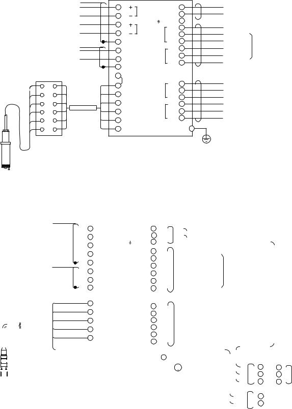
3-2-1. Wiring of DO30G
|
|
*1 |
|
DO402G |
|
|
|
|
|
|
|
|
|
|
|
|
*3 |
|
|
|
|
Output signal |
|
|
61 |
|
L |
1 |
|
|
|
|
|
|
|
|
|
|
|
||||
(4 to 20mA DC or 0 to 20mA DC) |
|
mA 1 |
|
|
Power supply |
|
||||
|
62 |
N |
2 |
|
|
|
||||
|
|
|
|
|
|
|
|
|||
|
|
|
|
G |
3 |
|
|
|
|
|
Output signal |
|
|
65 |
|
*3 |
C |
|
|
||
|
|
mA 2 |
|
31 |
Contact |
|
||||
(4 to 20mA DC or 0 to 20mA DC) |
|
66 |
|
|
NC |
|
||||
|
|
S1 |
32 |
|
|
|||||
|
|
|
|
|
NO |
output S1 |
|
|||
|
|
|
63 |
SCREEN |
|
33 |
|
|
||
|
|
*1 |
|
|
|
High and low |
||||
|
|
|
|
C |
|
|||||
Contact input |
|
|
21 |
|
|
41 |
|
|
alarms or HOLD |
|
|
|
|
|
|
NC |
Contact |
||||
|
|
|
S2 |
42 |
|
|
||||
(cleaning start command) |
|
|
22 |
|
|
output S2 |
|
|||
|
|
|
|
|
43 |
|
NO |
|
||
|
|
|
|
|
|
|
|
|||
|
|
|
|
|
|
|
|
|
||
|
|
|
23 |
SCREEN |
|
|
|
|
|
|
|
|
|
|
|
|
|
|
|
||
WTB10 Terminal box |
|
17 |
|
|
|
*3 |
C |
|
|
|
13 |
*4 |
|
Jumper |
|
51 |
|
|
|||
|
|
13 IE |
|
|
NC |
Contact output S3 (cleaning, |
||||
|
|
S3 |
52 |
|
||||||
11 |
|
|
11 T1 |
|
NO |
HOLD or high and low alarms) |
||||
|
|
|
53 |
|
||||||
12 |
*5 |
|
|
|
|
|
C |
|
|
|
|
12 T2 |
|
71 |
|
Contact output S4/FAIL |
|||||
|
|
|
|
|||||||
14 |
|
|
14 |
Shield |
S4 |
72 |
|
NC |
||
|
|
|
(failure or high and low alarms) |
|||||||
|
|
|
NO |
|||||||
15 |
|
|
15 RE |
|
73 |
|
|
|
||
|
|
|
|
|
|
|
||||
|
|
|
|
|
|
|
|
|||
16 |
|
|
16 |
Liquid earth *6 |
|
|
|
Grounding terminal (M4 screw) *2 |
||
|
|
|
|
|
|
|
|
|
Protective grounding (100Ω or less) |
|
|
|
Note : External wiring connection terminal size is for Ø2 pin. |
|
|
|
|||||
|
|
*1: Always use a shielded cable with an OD of 6 to 12 mm. |
|
|
|
|
||||
DO30G |
|
*2: Be sure to ground the DO converter case grounding terminal (grounding resistance of 100Ω or less). |
||||||||
|
*3: Always use a cable with an OD of 6 to 12 mm. |
|
|
|
|
|||||
DO sensor |
|
*4: Terminal box is used only where DO converter is installed long distance from DO sensor. (ordinary not needed) |
||||||||
*5: This cable is specified in the Basic Code for the WTB10.
*6: Liquid earth to detect membrane failure. This function is available when using PB350G/PB360G float type holder. Connect only when using this function.
Figure 3-4. wiring of DO30G (Example)
3-2-2. Wiring of DO70G
|
|
|
|
|
|
|
|
1 |
|
|
|
|
|
|
|
DO402G |
|
|
|
|
|
|
|
|
|
|
|
|
|
|
|
|
|
|
|
|
|
|
|
|
|
|
|
|
|
|
|||
|
|
|
|
|
|
|
|
|
|
|
|
|
|
|
|
|
|
|
|
|
|
|
|
|
|
3 |
|
|
|
|
|
|
|
|
|
|
|
|
|
|
|
|
|
||||||
|
|
Output signasl |
|
|
|
|
|
61 |
|
|
|
L |
1 |
|
|
|
|
|
|
|
|
|
|
|
|
|
|
|
|
|
|
|
|||||||||||||||||
|
|
|
|
|
|
|
|
|
|
|
|
|
|
|
|
|
|
|
|
|
|
|
|
|
|
|
|
|
|
|
|
|
|
||||||||||||||||
|
|
4 to 20mA DC or |
|
|
|
|
|
mA1 |
|
|
|
|
|
|
|
|
|
|
|
|
|
|
|
|
|
|
|
|
|
|
|
|
|
|
|||||||||||||||
|
|
0 to 20mA DC |
|
|
|
|
|
|
|
62 |
|
|
|
N |
2 |
|
|
|
|
|
|
|
|
|
Power supply |
|
|
|
|
|
|
|
|
|
|
|
|
|
|
||||||||||
|
|
|
|
|
|
|
|
|
|
|
|
|
|
|
|
|
|
|
|
|
|
|
|
|
|
|
|
|
|
|
|
|
|
||||||||||||||||
|
|
|
|
|
|
|
|
|
|
|
|
G |
3 |
|
|
|
|
|
|
|
|
|
|
|
|
|
|
|
|
|
|
|
|
|
|
|
|||||||||||||
|
|
|
|
|
|
|
|
|
|
|
|
|
|
|
|
|
|
|
|
|
|
|
|
|
|
|
|
|
|
|
|
|
|
||||||||||||||||
|
|
Output signal |
|
|
|
|
|
|
|
|
|
|
|
|
|
|
|
|
|
|
|
|
|
|
|
|
|
|
|
|
|
|
|
|
|
|
|
|
|
||||||||||
|
|
|
|
|
|
|
|
|
65 |
|
|
|
|
|
|
3C |
|
|
|
|
|
|
|
|
|
|
|
|
|
|
|
|
|
||||||||||||||||
|
|
4 to 20mA DC or |
|
|
|
|
|
|
mA2 |
|
|
|
31 |
|
|
|
|
|
|
|
|
|
|
|
|
|
|
|
|
|
|
|
|||||||||||||||||
|
|
0 to 20mA DC |
|
|
|
|
|
|
|
66 |
|
|
S1 |
|
32 |
|
|
|
|
NC |
|
|
Contact |
|
|
|
|
|
|
|
|
|
|
|
|
|
|
||||||||||||
|
|
|
|
|
|
|
|
|
|
|
|
|
|
|
|
|
|
|
|
|
|
|
|
|
|
|
|
|
|
|
|||||||||||||||||||
|
|
|
|
|
|
|
|
1 |
|
|
|
63 |
|
|
|
|
|
|
|
|
NO |
|
|
|
|
|
|
|
|
|
|
|
|
|
|
|
|
||||||||||||
|
|
|
|
|
|
|
|
|
|
|
|
|
|
|
|
|
|
|
|
|
|
|
|
|
|
|
|
|
|
|
|
|
|
|
|
|
|
|
|
|
|
||||||||
|
|
|
|
|
|
|
|
|
|
|
|
|
|
|
|
|
33 |
|
|
|
|
|
|
signal S1 |
High and Low alarms |
|
|
|
|
|
|||||||||||||||||||
|
|
|
|
|
|
|
|
|
|
|
|
21 |
|
|
|
|
|
|
|
|
|
|
C |
|
|
|
|
|
|
|
|||||||||||||||||||
|
|
|
|
|
|
|
|
|
|
|
|
|
|
|
|
|
|
|
|
|
|
|
|
|
|
|
|
|
|
|
|
|
|
|
|
||||||||||||||
|
|
|
|
|
|
|
|
|
|
|
|
|
|
|
|
|
|
|
41 |
|
|
|
|
|
|
|
and HOLD |
|
|
|
|
|
|
|
|
||||||||||||||
|
|
Remote contact input |
|
|
|
|
|
|
|
|
|
|
|
|
|
|
|
|
|
|
|
|
|
|
|||||||||||||||||||||||||
|
|
|
|
|
|
22 |
|
|
|
|
|
|
|
|
|
|
NC |
|
|
|
|
|
|
|
|
|
|
|
|||||||||||||||||||||
|
|
|
|
|
|
|
|
|
|
|
|
|
|
|
|
|
|
|
|
|
|
|
|
|
|
|
|
|
|
|
|
|
|
|
|
|
|
||||||||||||
|
|
Cleaning start |
|
|
|
|
|
|
|
|
|
|
S2 |
|
42 |
|
|
|
|
|
|
Contact |
|
|
|
|
|
|
|
|
|
|
|
|
|
|
|||||||||||||
|
|
|
|
|
|
|
|
|
|
|
|
|
|
|
|
|
|
|
|
|
|
|
|
|
|
|
|
|
|
|
|
|
|
|
|
|
|||||||||||||
|
|
|
|
|
|
|
|
|
|
|
|
|
|
|
|
|
NO |
|
|
|
|
|
|
|
|
|
|
|
|
|
|
|
|
||||||||||||||||
|
|
|
|
|
|
|
White |
|
|
|
23 |
|
|
|
|
|
|
43 |
|
|
|
|
|
|
signal S2 |
|
|
|
|
|
|
|
|
|
|
|
|
|
|
||||||||||
|
|
|
|
|
|
|
|
|
|
|
|
|
|
|
|
|
|
|
|
|
|
|
|
|
|
|
|
|
|
|
|
|
|
|
|
|
|
|
|
||||||||||
|
|
|
|
|
|
|
|
|
|
|
|
|
|
|
|
|
|
3C |
|
|
|
|
|
|
|
|
|
|
|
|
|
|
|
|
|||||||||||||||
|
|
|
|
|
|
|
|
|
11 |
|
|
|
|
|
|
|
|
|
|
51 |
|
|
|
|
|
|
|
|
|
|
|
|
|
|
|
|
|
|
|
||||||||||
|
|
|
|
|
|
|
Green |
|
|
12 |
|
|
|
S3 |
|
|
|
|
|
|
|
|
|
NC |
|
|
Contact signal S3 Cleaning |
|
|
|
|
|
|
|
|
||||||||||||||
|
|
|
|
|
|
|
|
|
|
|
|
|
52 |
|
|
|
|
|
|
|
|
|
|
|
|
|
|
||||||||||||||||||||||
|
|
|
|
|
|
|
|
|
|
|
|
|
|
|
|
|
|
|
|
|
|
|
|
|
|
|
|
|
|||||||||||||||||||||
|
|
|
|
|
|
|
Green/Yellow |
14 |
|
|
|
|
|
|
|
|
53 |
|
|
|
|
NO |
|
|
HOLD or High and Low alarms |
|
|
|
|
|
|
||||||||||||||||||
|
|
|
|
|
|
|
Clear |
|
|
|
|
|
|
|
|
|
|
|
|
|
|
C |
|
|
|
|
|
|
|
|
|
|
|
|
|
|
|
|
|
||||||||||
|
|
|
|
|
|
|
|
|
17 |
|
|
|
|
|
|
|
|
|
71 |
|
|
|
|
|
|
|
|
|
|
|
|
|
|
|
|
|
|
|
|
|
|
|
|
|
|||||
|
|
|
|
|
|
|
|
|
|
|
|
|
|
S4 |
|
|
|
|
|
|
|
NC |
|
|
Contact signal S4/FAIL Failure |
|
|
|
|
|
|
||||||||||||||||||
|
|
|
|
|
|
|
Red |
|
|
|
|
|
|
|
|
|
72 |
|
|
|
|
|
|
|
|
|
|
|
|
||||||||||||||||||||
|
|
|
|
|
|
|
|
|
18 |
|
|
|
|
|
|
|
|
NO |
|
|
or High and Low alarms |
|
|
|
|
|
|
|
|
||||||||||||||||||||
|
|
|
|
|
|
|
|
|
|
|
|
|
|
|
|
|
|
73 |
|
|
|
|
|
|
|
|
|
|
|
|
|
|
|||||||||||||||||
|
|
|
|
|
|
|
|
|
|
|
|
|
|
|
|
|
|
|
|
|
|
|
|
|
|
|
|
|
|
|
|
|
|
|
|
|
|
|
|
|
|
|
|
|
|
||||
|
|
|
|
|
|
|
|
|
|
|
|
|
|
|
|
|
|
|
|
|
|
|
|
|
|
|
|
|
|
|
|
|
|
|
|
|
|
|
|
|
|
|
|
|
|||||
|
|
|
|
|
|
|
|
|
|
|
|
|
|
|
|
|
|
|
|
|
|
|
|
|
|
|
|
|
|
|
|
|
|
|
|
|
|
|
|
|
|
|
|
|
|
|
|
|
|
|
|
|
|
|
|
|
|
|
|
|
|
|
|
|
|
|
|
|
|
|
|
|
|
|
|
|
|
|
|
|
|
|
|
|
|
|
|
|
|
|
|
|
|
|
|
|
|
|
|
|
|
DO70G |
|
|
|
|
|
|
|
|
|
|
|
|
|
|
|
|
|
|
|
|
|
|
Grounding terminal |
|
|
|
|
|
3 |
DOX10 Poewr supply unit |
|||||||||||||||||
|
|
|
|
|
|
|
|
|
|
|
|
|
|
|
|
|
|
|
|
|
|
|
|
|
|
|
|
|
|||||||||||||||||||||
|
|
|
|
|
|
|
|
|
|
|
|
|
|
|
|
|
|
|
|
2 |
M4 screw |
|
|
|
|
|
|
|
|
|
|
|
3 |
||||||||||||||||
|
|
|
|
|
|
|
|
|
|
|
|
|
|
|
|
|
|
|
|
|
|
|
|
|
|
|
|
|
|
|
|||||||||||||||||||
|
|
Optical dissolved |
Note : External wiring connection terminal size is for Ø2 pin. |
|
|
|
|
|
|
Protective grounding |
|
|
|
|
|
|
|
|
L |
L |
|
|
|
||||||||||||||||||||||||||
|
|
oxygen sensor |
|
|
|
|
|
|
|
|
|
|
|
|
|
|
|
|
Power |
||||||||||||||||||||||||||||||
|
|
|
|
|
|
|
|
|
|
|
|
|
|
|
|
|
|
|
|
|
|
|
|
|
|
|
|
|
|
|
|
|
|
|
|
|
|
|
|
|
|
|
|
|
|
|
|
|
|
|
|
|
|
|
|
|
|
|
|
|
|
|
|
|
|
|
|
|
|
|
|
|
|
|
|
|
|
|
|
|
|
|
(100Ω or less) |
|
|
|
|
|
|
|
|
N |
N |
|
|
||||
|
|
|
*1: Always use a shielded cable with an OD of 6 to 12 mm. |
|
|
|
|
|
|
|
|
|
|
|
|
|
|
|
|
|
|
|
|
|
|
|
|
G |
G |
|
|
supply |
|||||||||||||||||
|
|
|
|
|
|
|
|
|
|
|
|
|
|
|
|
|
|
|
|
|
|
|
|
|
|
|
|
|
|
||||||||||||||||||||
|
|
|
|
|
|
|
|
|
|
|
|
|
|
|
|
|
|
|
|
|
|
|
|
|
|
|
|
|
|
|
|
|
|||||||||||||||||
|
|
|
*2: Be sure to ground the DO converter case grounding terminal (grounding resistance of 100Ω or less). |
|
|
Brown |
|
|
|
|
|
|
|
|
|||||||||||||||||||||||||||||||||||
|
|
|
*3: Always use a cable with an OD of 6 to 12 mm. |
|
|
|
|
|
|
|
|
|
|
|
|
|
|
|
|
|
|
|
|
|
|
|
+ (BROWN) |
|
|
||||||||||||||||||||
|
|
|
|
|
|
|
|
|
|
|
|
|
|
|
|
|
|
|
|
|
|
|
|
|
|
|
|
|
|
|
|
|
|
|
|
|
|
|
|
|
|
|
|
|
|
||||
|
|
|
|
|
|
|
|
|
|
|
|
|
|
|
|
|
|
|
|
|
|
|
|
|
|
|
|
|
|
|
|
|
|
|
|
|
|
|
|
|
|
|
|
‒ (BLUE) |
|
|
|||
|
|
|
|
|
|
|
|
|
|
|
|
|
|
|
|
|
|
|
|
|
|
|
|
|
|
|
|
|
|
|
|
|
|
|
|
|
|
|
Blue |
|
|
F11.eps |
|||||||
|
|
|
|
|
|
|
|
|
|
|
|
|
|
|
|
|
|
|
|
|
|
|
|
|
|
|
|
|
|
|
|
|
|
|
|
|
|
|
|
|
|||||||||
|
|
|
|
|
|
|
|
|
|
|
|
|
|
|
|
|
|
|
|
|
|
|
|
|
|
|
|
|
|
|
|
|
|
|
|
|
|
|
|
|
|
|
|
|
|||||
|
|
|
|
|
|
|
|
|
|
|
|
|
|
|
|
|
|
|
|
|
|
|
|
|
|
|
|
|
|
|
|
|
|
|
|
|
|
|
|
|
|
|
|
|
|
|
|
|
|
Figure 3-5. wiring of DO70G (Example)
IM 12J05D02-01E

3-4 Installation and wiring
 DANGER
• Never apply power to the DO402G converter and other instruments connected to the DO402G converter until all wiring is completed.
WARNING
•This product complies with the CE marking.
Where compliance with the CE marking and relevant standard is necessary, the following wiring is required.
1.Install an external switch or circuit breaker to the power supply of the DO402G converter.
2.Use an external switch or circuit breaker rated 5A and conforming to IEC 60947-1 or IEC 60947-3.
3.It is recommended that the external switch or circuit breaker be installed in the same room as the
DO402G converter.
4.The external switch or circuit breaker should be installed within reach of the operator and identified with marking as a power supply switch to the DO402G converter.
5.Power lines such as power cables and contact outputs should be fixed securely onto a wall or construction using cable racks, conduit tubing, nylon bands or other appropriate ways. Accidental removal from terminals by pulling may result in electric shock.
3-2-3. Preparation
The relay contact terminals and power supply connections are under the screening (shielding) plate. These should be connected first. Connect the sensor, outputs and data communication connections last.
Follow the procedures below to open the DO402G for wiring: 1. Loosen the four frontplate screws and remove the cover.
2. Use the rubber knob in the lower right hand corner and swing open the display board to the left.
3. The upper terminal strip is now visible.
4. Remove the screen (shield) plate covering the lower terminal strip.
5. Connect the power supply and contact outputs. Use the three glands at the back for these cables. 6. Replace the screen (shield) plate over the lower terminals.
 WARNING
Always replace the screen plate over the power and contact outputs for safety and to avoid interference.
7.Connect the analog output(s), the sensor input, the contact input and, if necessary, the RS485 serial bus.
8.Use the front three glands for analog output, sensor input, contact input and communication cabling (see figure 3-6).
9.Close the display board and switch on the power. Commission the instrument as required or use the default settings.
10.Replace the cover and secure frontplate with the four screws. Tighten four frontplate screws to 1.5 N·m torque.
IM 12J05D02-01E
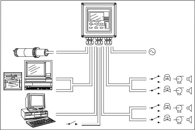
Installation and wiring 3-5
front glands |
rear glands |
Sensor |
Power |
|
output |
contact |
S1 |
signals |
output |
|
|
|
S2 |
|
contact |
S3 |
rs485 |
|
|
output |
|
|
|
|
|
|
|
S4/FAIL |
contact intput |
|
|
Figure 3-6. System configuration
3-3. Wiring the power supply
3-3-1. General precautions
Make sure the power supply is switched off. Also, make sure that the power supply is correct for the specifications of the EXA and that the supply agrees with the voltage specified on the textplate. Remove the front cover by unscrewing the four screws to check this textplate on the top of the display board.
Local health and safety regulations may require an external circuit breaker to be installed. The instrument is protected internally by a fuse. The fuse rating is dependent on the supply to the instrument. The
250 VAC fuses should be of the “time-lag” type, conforming to IEC60127.
The internal fuse is located next to the power terminals (in the lower right hand corner).
 DANGER
Use only a fuse of the specified current, voltage and type ratings to prevent fire. For fuse replacement, refer to Section 7-3, “Fuse Replacement.”
IM 12J05D02-01E
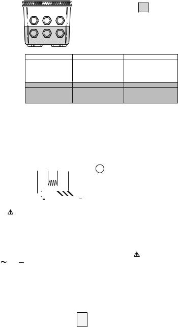
3-6 Installation and wiring
3-3-2. Access to terminal and cable entry
Terminals 1 and 2 on the bottom terminal strip are used for the power supply. Guide the power cables through the gland closest to the power supply terminals. The terminals will accept wires of 2.5 mm2 (14
AWG). Use cable finishings if possible.
Connect the wires as indicated in the wiring diagram (refer to figure 3-6).
|
|
|
High Voltage Section |
|
A |
B |
C |
|
|
D |
E |
F |
|
|
|
|
A |
B |
C |
POWER CABLE |
SENSOR CABLE (S) |
ANALOG OUTPUTS |
||
|
for DO70G or |
|
CABLE |
|
COMMUNICATION |
|
|
||
INPUT CONTACT |
|
|
||
|
|
D |
E |
F |
CONTACT (S3, S4/FAIL) |
CONTACT (S1, S2) |
POWER CABLE |
||
OUTPUT CABLE (S) |
OUTPUT CABLE (S) |
|
||
Suitable for cables with an outside diameter between 6 - 12 mm (0.24 - 0.47 in.)
Figure 3-7. Glands to be used for cabling
Contact |
|
Sensor Inputs |
|
|
|
|
|
|
|
|
|
|
|
|
mA Outputs |
|
|
|
|
|
|
|
|
|
|
|
|
|
Digital |
|
|
|
|
|
|
|
|
|||||||||||||||||||||||||
Input |
|
|
|
|
|
|
|
|
|
|
|
|
|
|
|
|
|
|
|
|
|
|
|
|
|
|
Communications |
|
||||||||||||||||||||||||||||||||||
|
|
|
|
|
|
|
|
|
|
|
|
|
|
|
|
|
|
|
|
|
|
|
|
|
|
|
|
|
|
|
|
|
|
|
|
|
|
|
|
|
|
|
|
|
|
|
|
|
|
|
|
|
|
|
||||||||
|
|
|
|
|
|
|
|
|
|
|
|
|
|
|
|
|
|
|
|
|
|
|
|
|
|
|
|
|
|
|
|
|
|
|
|
|
|
|
|
|
|
|
|
|
|
|
|
|
|
|
|
|
|
|
||||||||
22 |
|
14 |
13 |
17 |
11 |
12 |
18 |
16 |
15 |
|
|
63 |
66 |
65 |
62 |
61 |
|
95 |
94 |
93 |
|
92 |
91 |
|||||||||||||||||||||||||||||||||||||||
21 |
|
|
|
|
|
|
||||||||||||||||||||||||||||||||||||||||||||||||||||||||
|
|
|
|
|
|
|
|
|
|
|
|
|
|
|
|
|
|
|
|
|
|
|
|
|
|
|
|
|
|
|
|
|
|
|
|
|
|
|
|
|
|
|
|
|
|
|
|
|
|
|
|
|
|
|
|
|||||||
|
SCREEN |
|
|
|
|
|
|
|
|
|
|
|
|
|
|
|
|
Liquid |
|
|
|
|
|
|
|
mA2 |
|
|
|
|
|
|
mA1 |
|
|
|
|
TL |
|
|
|
|
|
|
|
TL |
||||||||||||||||
|
|
|
|
|
|
Shield |
|
|
|
|
|
|
|
|
|
|
|
earth |
|
|
|
|
|
|
|
|
|
|
|
SCREEN |
|
|
|
|
|
|
|
|
|
|
|
|
SCREEN |
|
|
|
|
|
||||||||||||||
23 |
|
|
|
|
|
|
|
|
|
|
|
Temp |
|
|
|
|
|
|
|
|
|
|
|
|
|
|
|
|
|
|
|
|
|
|
|
|
|
|
|
|
|
|
|
|
99 |
|
|
|
|
|
|
|
|
|||||||||
|
|
|
|
|
|
|
|
|
|
|
|
|
|
|
|
|
|
|
|
|
|
|
|
|
|
|
|
|
|
|
|
|
|
|
|
|
|
|
|
|
|
|
|
|
|
|
|
|
|
|
||||||||||||
|
|
|
|
|
|
|
|
|
|
|
|
|
|
|
|
|
|
|
|
|
|
|
|
|
|
|
|
|
|
|
|
|
|
|
|
|
|
|
|
|
|
|
|
|
|
|
|
|
|
|
|
|
|
|
|
|
||||||
|
|
|
|
|
|
|
|
|
|
|
|
|
|
|
|
|
|
|
|
|
|
|
|
|
|
|
|
|
|
|
|
|
|
|
|
|
|
|
|
|
|
|
|
|
|
|
|
|
|
SCREEN 2 |
|
|
|
|
|
|||||||
|
|
|
|
|
|
|
|
|
|
|
|
|
|
|
|
|
|
|
|
|
|
|
|
|
|
|
|
|
|
|
|
|
|
|
|
|
|
|
|
|
|
|
|
|
|
|
|
|
|
|
|
|
|
|
||||||||
|
CONT |
|
|
|
|
|
|
|
|
SENSOR |
|
|
|
|
|
|
|
|
|
mA OUTPUT |
|
|
|
|
|
|
|
|
|
RS485 |
|
|
|
|
|
|||||||||||||||||||||||||||
|
|
|
|
|
|
|
|
|
|
- - - optical sensor and polarographic sensor |
|
|
|
|
|
galvanic sensor |
|
|
|
|
|
|
|
|
||||||||||||||||||||||||||||||||||||||
|
|
|
|
|
|
|
|
|
|
|
|
|
|
|
|
|
|
|
|
|
|
|
||||||||||||||||||||||||||||||||||||||||
|
|
|
|
|
|
|
|
|
|
|
|
|
|
|
|
|
|
|
|
|
|
|
|
|
|
|
|
|
|
|
|
|
|
|
|
|
|
|
|
|
|
|
|
|
|
|
|
|
|
|
|
|
|
|
|
|
|
|
|
|
|
|
|
Relay Contacts |
|
|
|
|
|
|
|
|
|
|
|
|
|
|
|
|
|
|
|
|
Power Supply |
|
|
|
|
|
|
|
|
|
|
|
|
|
|
|
|
|
|||||||||||||||||||||||
|
|
|
|
|
|
|
|
|
|
|
|
|
|
|
|
|
|
|
|
|
|
|
|
|
|
|
|
|
|
|
|
|
|
|
|
|
|
|
|
|
|
|
|
|
|
|
|
|
|
|
|
|
|
|
|
|
|
|
|
|
|
|
|
|
|
|
|
|
|
|
|
|
|
|
|
|
|
|
|
|
|
|
|
|
|
|
|
|
|
|
|
|
|
|
|
|
|
|
|
|
|
|
|
|
|
|
|
|
|
|
|
|
|
|
|
|
|
|
|
|
|
|
|
|
|
|
71 |
|
72 |
|
73 |
51 |
|
52 |
|
53 |
41 |
|
42 |
|
43 |
31 |
32 |
|
33 |
|
|
|
|
|
|
|
|
|
|
3 |
|
|
2 |
|
|
1 |
|
|
|
|
|
|
|
|
|
|
|
|||||||||||||||
|
250VAC |
|
250VDC |
|
|
|
|
|
|
|
|
|
|
|
|
|
|
|
|
|
|
|
|
|
|
|
|
|
|
|
|
|
|
|
|
|
G |
N |
|
L |
|
|
FUSE |
|||||||||||||||||||
|
|
|
|
|
|
|
|
|
|
|
|
|
|
|
|
|
|
|
|
|
|
|
|
|
|
|
|
|
|
|
|
|
|
|
|
|
|
|
|
|
|
|
|
|
|
|
|
|
||||||||||||||
|
|
|
5A |
|
|
|
5A |
|
|
|
|
|
|
|
|
|
|
|
|
|
|
|
|
|
|
|
|
|
|
|
|
|
|
|
|
|
|
|
|
|
|
|
|
|
|
|
|
|
|
|
|
|
|
|
|
|
|
|
|
|
|
|
|
|
|
|
|
|
|
|
|
|
|
|
|
|
|
|
|
|
|
|
|
|
|
|
|
|
|
|
|
|
|
|
|
|
|
|
|
|
|
|
|
|
|
|
|
|
|
|
|
|
|
|
|
|
|
|
|
|
|
||||
|
|
100VA |
|
|
50W |
|
|
|
|
|
|
|
|
|
|
|
|
|
|
|
|
|
|
|
|
|
|
|
|
|
|
100 VAC |
|
|
|
200 |
|
mA |
|
|
|
|
|
|
|
|
||||||||||||||||
|
|
|
|
|
|
|
|
|
|
|
|
|
|
|
|
|
|
|
|
|
|
|
|
|
|
|
|
|
|
|
|
|
|
|
|
|
|
|
|
|
|
|
|
|
|
|
|
|||||||||||||||
|
C |
|
NC |
|
NO |
C NC NO |
C NC NO |
C |
NC |
NO |
|
|
|
115 VAC |
|
|
|
200 |
|
mA |
|
250VAC; T |
||||||||||||||||||||||||||||||||||||||||
|
|
|
|
|
|
230 VAC |
|
|
|
100 |
|
mA |
|
|||||||||||||||||||||||||||||||||||||||||||||||||
|
|
|
|
|
|
|
|
|
|
|
|
|
|
|
|
|
|
|
|
|
|
|
|
|
|
|
|
|
|
|
|
|
|
|
|
|
|
|
|
|
|
|
|
|
|
|
|
|
|
|
|
|
|
|
|
|||||||
|
|
|
|
|
S4 |
|
|
|
|
|
|
S3 |
|
|
|
|
|
S2 |
|
|
|
|
S1 |
|
|
|
|
|
|
|
|
|
|
|
|
|
|
|
|
|
|
|
|
|
|
|
|
|
|
|
|
|
|
|
|
|||||||
|
|
|
|
|
|
|
|
|
|
|
|
|
|
|
|
|
|
|
|
|
|
|
|
|
|
|
|
|
|
|
|
|
|
|
|
|
|
|
|
|
|
|
|
|
|
|
|
|
|
|
|
|
|
|
|
|
|
|
|
|
|
|
High voltage compartment
Figure 3-8. Input and output connections
IM 12J05D02-01E

Installation and wiring 3-7
3-3-3. AC power
Connect terminal 1 to the phase line of the AC power and terminal 2 to the zero line. The size of conductors should be at least 1.25 mm2. The overall cable diameter should be between 6 & 12 mm (0.24 & 0.47 in).
3-3-4. Grounding the housing
 DANGER
Protective grounding must be made to prevent electric shock.
To protect the instrument against interference, the housing should be connected to ground by a large area conductor. This cable can be fixed to the rear of the housing using a braided wire cable. See figure 3-9. This is separated from input ground by a galvanic isolation.
 CAUTION
Please be sure to connect protective grounding of
DO402G with cable of 1.25 mm2 or larger cross section in order to avoid the electrical shock to the operators and maintenance engineers and prevent the influence of external noise. And further connect the grounding wire to the  mark (100Ω or less).
3-3-5. Switching on the instrument
After all connections are made and checked, the
power can be switched on from the power supply. Make sure the LCD display comes on. All segments will illuminate, then the instrument will momentarily display its unique serial number. After
a brief interval, the display will change to the measured value. If errors are displayed or a valid meas-
ured value is not shown, consult the troubleshooting section (Chapter 8) before calling Yokogawa.
(M4 screw)
Figure 3-9. Grounding the housing
IM 12J05D02-01E
3-8 Installation and wiring
3-4. Wiring the contact signals
3-4-1. General precautions
The contact output signals consist of voltage-free relay contacts for switching electrical appliances (SPDT). They can also be used as digital outputs to signal processing equipment (such as a controller or
PLC). It is possible to use multi-core cables for the contact in and output signals and shielded multi-core cable for the analog signals.
3-4-2. Contact outputs
The EXA unit’s four contact outputs can be wired to suit your own custom requirements (Figure 3-6).
In the Non-Alarm or Power Off states, contacts S1, S2 and S3 are OFF, Common (C) and Normally
Closed (NC) are in contact.
In the “Fail” or Power Off states, contact S4 is ON, Common (C) and Normally Closed (NC) are in contact.
You can either use them to switch AC power, or switch a DC Voltage for digital interfacing.
Default settings
•The contact S1 is pre-programmed for high alarm function.
•The contact S2 is pre-programmed for a low alarm function.
•The contact S3 is pre-programmed for wash function.
•The contact S4 is pre-programmed for FAIL.
 WARNING
The three control contacts (S1 to S3) can be used for simple process control by programming their function (Chapter 5). The FAIL contact is programmed to signal a fault in the measuring loop. Always connect the FAIL contact to an alarm device such as a warning light, sound annunciator, or alarm panel to make full use of the fault detection possibilities (self diagnostics) of the EXA converter.
3-4-3. Contact input
It is necessary to use screening/shielding on the output signal cables. Screw (M3) 23 is used to connect the shielding.
On resistance: 10Ω or less Off resistance: 100kΩ or more
IM 12J05D02-01E
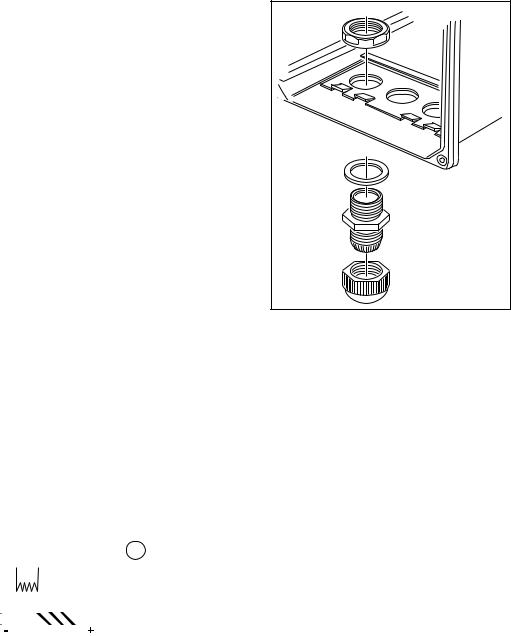
Installation and wiring 3-9
3-5. Wiring the analog output signals
3-5-1. General precautions
The analog output signals of the EXA transmit low power standard industry signals to peripherals like control systems or strip-chart recorders (Figure 3-6).
3-5-2. Analog output signals
The output signals consist of active current signals of either 0-20 mA or 4-20 mA. The maximum load can be 600 ohms on each.
It should be necessary to use screening/shielding on the output signal cables. Terminal 63 is used to connect the shielding.
3-6. Wiring the standard galvanic sensor
The sensor cable has markers on the individual wires. These markings refer to the markers on the terminals.
The temperature compensator has two wires with the markings
T1, T2 and/or 11, 12 and must be connected to terminal 11 and 12.
The measuring electrode: the cathode is marked with IE and/or 13
and must be connected to terminal 13.
The reference electrode: the anode is marked with RE and/or
15 and must be connected to terminal 15.
The liquid earth ( solution ground) is marked with 16 and must be connected to terminal 16.
Note: The liquid earth (solution ground) connection is valid
only when the floating ball holder, Model PB350G or PB360G, is used. Otherwise, do not make a connection to terminal 16. The connection, if made, may result in
abnormal readings. Even if the floating ball holder is
used, when the liquid earth (solution ground) connection is not used, then disconnect the wiring to terminal 16. (The disconnected wire should be covered with an insulating tube to avoid contact with other terminals.)
The overall shield of the cable is marked with 14 and must be connected to terminal 14. Note:
A jumper cable is placed to connect converter terminals 13 and 17.
Make sure that connecting the sensor cable to the IE pin or pin 13 or pulling the sensor cable does not cause the jumper cable to come loose. Insufficient tightening may cause unstable or false measurements.
Contact |
|
|
Short |
|
Sensor Input |
|
|
|
|
mA Output |
|
|
|
|
|
|
Digital |
|
|
|
|
|
|
|
||||||||||||||||||||||||||||||||
Input |
|
|
|
|
|
|
|
|
|
|
|
|
|
Commnucations |
||||||||||||||||||||||||||||||||||||||||||
|
|
|
|
|
|
|
|
|
|
|
|
|
|
|
|
|
|
|
|
|
|
|
|
|
|
|
|
|
|
|
|
|
|
|
|
|
|
|
|
|
|
|
|
|
|
|
|
|
|
|
|
|
|
|
|
|
|
|
|
|
|
|
|
|
|
|
|
|
|
|
|
|
|
|
|
|
|
|
|
|
|
|
|
|
|
|
|
|
|
|
|
|
|
|
|
|
|
|
|
|
|
|
|
|
|
|
|
|
|
|
|
|
|
|
|
|
|
|
|
|
|
|
|
|
|
|
|
|
|
|
|
|
|
|
|
|
|
|
|
|
|
|
|
|
|
|
|
|
|
|
|
|
|
|
|
|
|
|
|
|
|
|
|
|
|
|
|
|
|
|
22 |
14 |
13 |
17 |
11 |
12 |
18 |
16 |
|
15 |
63 |
66 |
65 |
62 |
61 |
95 |
94 |
93 |
92 |
91 |
|||||||||||||||||||||||||||||||||||||
21 |
|
|||||||||||||||||||||||||||||||||||||||||||||||||||||||
|
SCREEN |
Shield (IE) |
|
|
|
(T1) (T2) |
|
|
(LE) |
(RE) |
|
|
|
|
|
|
|
|
|
|
|
|
|
|
|
|
|
|
|
|
|
|
|
|
|
|
|
|
|
|
|
|
|
|
||||||||||||
|
|
|
|
|
|
|
|
|
|
|
|
|
|
|
|
|
|
|
|
|
|
|
|
|
|
|
|
|
|
|
|
|
|
|
|
|
|
|
||||||||||||||||||
|
|
|
|
|
|
|
|
|
mA2 |
|
|
|
|
|
mA1 |
|
|
|
|
|
|
|
|
|
|
|
|
|
|
|
|
|
|
|||||||||||||||||||||||
|
|
|
|
|
|
|
|
|
|
|
|
|
Liquid Earth |
|
|
|
|
|
|
|
|
|
|
|
|
|
|
|
TL |
|
|
|
|
|
|
TL |
|
|||||||||||||||||||
|
|
|
|
|
|
|
|
|
|
|
|
|
|
|
|
|
|
|
|
|
|
|
|
|
|
SCREEN |
||||||||||||||||||||||||||||||
|
|
|
|
|
|
|
|
|
|
|
|
|
|
|
|
|
|
|
|
|
|
|
|
|
|
|
|
|
|
|
|
SCREEN |
|
|
|
|
|
|
|
|
|
|
|
|||||||||||||
23 |
|
|
|
|
|
|
|
|
|
|
Temp. |
|
|
|
|
|
|
|
|
|
|
|
|
|
|
|
|
|
|
|
|
|
|
|
|
|
|
|
|
99 |
|
|
|
|
|
|
|
|
|
|||||||
|
|
|
|
|
|
|
|
|
|
|
|
|
|
|
|
|
|
|
|
|
|
|
|
|
|
|
|
|
|
|
|
|
|
|
|
|
|
|
|
|
|
|
|
|
|
|
|
|
|
|
|
|
||||
CONT |
|
|
|
|
|
|
|
|
|
|
|
|
|
|
|
|
|
|
|
|
mA OUTPUT |
|
|
|
SCREEN 2 |
|
|
|
|
|
|
|
||||||||||||||||||||||||
|
|
|
|
|
|
|
|
|
|
|
|
|
|
|
|
|
|
|
|
|
|
|
|
|
|
|
|
|
|
|||||||||||||||||||||||||||
|
|
|
|
|
|
|
|
|
|
|
|
|
|
|
|
|
|
|
|
|
|
|
|
|
|
|
|
|
|
|||||||||||||||||||||||||||
|
|
|
|
|
|
|
|
|
|
|
|
|
|
|
|
|
|
|
|
|
|
|
|
|
|
|
|
|
|
|
|
|
|
|
|
|||||||||||||||||||||
|
|
|
Wirning galvanic Sensor |
|
|
|
|
|
|
|
|
|
|
|
|
|
|
|
|
|
|
|||||||||||||||||||||||||||||||||||
|
|
|
|
|
|
|
|
|
|
|
|
|
|
|
|
|
|
|
|
|
|
|
|
|
|
|
|
|
|
|
|
|
|
|
|
|
|
|
|
|
|
|||||||||||||||
|
|
|
|
|
|
|
|
|
|
|
|
|
|
|
|
|
|
|
|
|
|
|
|
|
|
|
|
|
|
|
|
|
|
|
|
|
|
|
|
|
|
|
|
|
|
|
|
|
|
|
|
|
|
|
|
|
|
|
|
|
|
|
|
|
|
|
|
|
|
|
|
|
|
|
|
|
|
|
|
|
|
|
|
|
|
|
|
|
|
|
|
|
|
|
|
|
|
|
|
|
|
|
|
|
|
|
|
F0309.ai |
|||||
Figure 3-11. Wirning galvanic sensor |
|
|
|
|
|
|
|
|
|
|
|
|
|
|
|
|
|
|
|
|
|
|
|
|
|
|
|
|
|
|
|
|
|
|
|
|
|
|
|
|||||||||||||||||
IM 12J05D02-01E

3-10 Installation and wiring
3-7. Wiring other galvanic sensors
Consult the users manual for the color identification of the sensor cable and connect temperature compensator, cathode and anode to the terminals: 11, 12, 13 and 15 as described above.
Connect the cable shield to 14 if there is one available. Sensor diagnostics is normally not possible. Note:
A jumper cable is placed to connect converter terminals 13 and 17.
Make sure that connecting the sensor cable to the IE pin or pin 13 or pulling the sensor cable does not cause the jumper cable to come loose. Insufficient tightening may cause unstable or false measurements.
3-8. Wiring the standard optical sensor (DO70G)
Note:
The color of the wiring of the sensor cable supports the indication of each terminal.
Color of sensor cable |
White |
Green |
Green/Yellow |
Clear |
Red |
Brown |
Blue |
DO402G |
11 |
12 |
14 |
17 |
18 |
|
|
|
|
|
|
|
|
|
|
DOX10 |
|
|
|
|
|
+ |
– |
Contact |
|
|
|
|
|
Sensor Input |
|
|
|
|
|
mA Output |
|
|
|
|
|
Digital |
|
|
|
|
|
|
|
|
|
||||||||||||||||||||||||||||
Input |
|
|
|
|
|
|
|
|
|
|
|
|
|
|
|
Communications |
|||||||||||||||||||||||||||||||||||||||
|
|
|
|
|
|
|
|
|
|
|
|
|
|
|
|
|
|
|
|
|
|
|
|
|
|
|
|
|
|
|
|
|
|
|
|
|
|
|
|
|
|
|
|
|
|
|
|
|
|
|
|
|
|
|
|
22 |
14 |
13 |
17 |
11 |
12 |
18 |
16 |
15 |
63 |
66 |
65 |
62 |
61 |
95 |
94 |
93 |
92 |
91 |
|||||||||||||||||||||||||||||||||||||
21 |
|||||||||||||||||||||||||||||||||||||||||||||||||||||||
|
SCREEN |
Shield |
|
|
|
|
|
|
|
|
|
|
|
|
|
|
|
|
|
|
|
|
|
|
|
|
|
|
|
|
|
|
|
|
|
|
|
|
|
|
|
|
|
|
|
|
|
|
|
|
|
||||
|
|
|
|
|
|
|
|
|
|
|
|
|
|
|
|
|
|
|
|
|
|
mA2 |
|
|
|
|
|
mA1 |
|
|
|
|
|
TL |
|
|
|
|
|
TL |
|||||||||||||||
|
|
|
|
|
|
|
|
|
|
|
|
|
|
|
|
|
|
|
|
|
|
|
|
|
|
|
|
|
|
|
SCREEN |
||||||||||||||||||||||||
|
|
|
|
|
|
|
|
|
|
|
|
Temp. |
|
|
|
|
|
|
|
|
|
|
|
|
|
|
|
SCREEN |
|
|
|
|
|
|
|
|
|
|
|
||||||||||||||||
|
|
|
|
|
|
|
|
|
|
|
|
|
|
|
|
|
|
|
|
|
|
|
|
|
|
|
|
|
|
|
|
|
|
|
|
|
|
||||||||||||||||||
23 |
|
|
|
|
|
|
|
|
|
|
|
|
|
|
|
|
|
|
|
|
|
|
|
|
|
|
|
|
|
|
|
|
|
|
|
|
|
99 |
|
|
|
|
|
|
|
|
|
||||||||
|
|
|
|
|
|
|
|
|
|
|
|
|
|
|
|
|
|
|
|
|
|
|
|
|
|
|
|
|
|
|
|
|
|
|
|
|
|
|
|
|
|
|
|
|
|
|
|
|
|||||||
|
|
|
|
|
|
|
|
|
|
|
|
|
|
|
|
|
|
|
|
|
|
|
|
|
|
|
|
|
|
|
|
|
|
|
|
|
|
|
|
|
|
|
|
|
|
|
|
|
|
|
|||||
CONT |
|
|
|
|
|
|
|
|
|
|
|
|
|
|
|
|
|
|
|
mA OUTPUT |
|
|
|
SCREEN 2 |
|
|
|
|
|
|
|
||||||||||||||||||||||||
|
|
|
Wiring optical sensor |
|
|
|
|
|
|
|
|
|
|
|
|
|
|
||||||||||||||||||||||||||||||||||||||
|
|
|
|
|
|
|
|
|
|
|
|
|
|
|
|
|
|
|
|
|
|
|
|||||||||||||||||||||||||||||||||
|
|
|
|
|
|
|
|
|
|
|
|
|
|
|
|
|
|
|
|
|
|
|
|
|
|
|
|
|
|
|
|
|
|
|
|
|
|
|
|
|
|
|
|
|
|
|
|
|
|
|
|
|
|
|
|
|
|
|
|
|
|
|
|
|
|
|
|
|
|
|
|
|
|
|
|
|
|
|
|
|
|
|
|
|
|
|
|
|
|
|
|
|
|
|
|
|
|
|
|
|
|
|
|
|
F0311.ai |
||||||
|
|
|
|
|
|
|
|
|
|
|
|
|
Figure 3-12. Wiring optical sensor |
|
|
|
|
|
|
|
|
|
|
|
|
|
|
|
|
|
|
|
|
||||||||||||||||||||||
IM 12J05D02-01E
Loading...